Embed Size (px)
Citation preview

Three-Wheeled RoverAutonomous three wheeled robot capable of obstacle avoidance
Group 14Available for labs on both Monday and Thursday
Proposed by:Mikael Rouhiainen [email protected]
Peter Hu [email protected] a

Abstract
The goal of this project is to create an autonomous robot vehicle that can navigate through an obstacle course. This document details the design process of the robot. The scope of the robots capability will be limited to navigating a pre-made obstacle course and successfully avoiding any collisions. Infrared sensors mounted on the front and sides of the robot are used to detect obstacles. When an obstacle is encountered, navigation logic is used to look for an available path to progress down the course and the robot will turn accordingly. A digital compass is integrated into the robot to maintain a sense of direction and progress down the obstacle course. These components are connected to the Altera DE0-Nano FPGA board, along with motors that the DE0-Nano will control by sending pulse width modulated control signals.

Table of Contents
1. Functional Requirements of Project 1
2. Design and Description of Operation2.1 Description of Operation 22.2 Hardware Design 32.3 Software Design 8
3. Hardware Requirements 9
4. Bill of Materials 11
5. Reusable Design Units 14
6. Datasheet 15
7. Background Reading 18
8. Test Plan 19
9. Experimental Results and Characterization 21
10. References 22
11. Appendix11.1 Quick Start Manual 23 11.2 Future Work 2311.3 Hardware Documentation
11.3.1. Hardware Block Diagram 2411.3.2. Robot Schematic 2511.3.3. H-Bridge Circuit 2611.3.4. Hardware Wiring Diagram 2711.3.5. Obstacle Course Diagram 2811.3.6. Navigation Logic Block Diagram 29
11.4 Source Code 30

1. Functional Requirements of Project
Core Requirements and Features
1. Working motors that can go forward, reverse and stop2. Infrared sensors that can detect obstacles3. Compass returns accurate readings to use in logic4. Encoders to determine rover speed5. Navigation through an obstacle course without collision or looping6. Have “maze complete” termination7. Use servo with front IR sensor to increase rover's field of view
Requirement Status Completion
Overall, we met most of the requirements we had set out for the rover. Motors, sensors, encoders, servo components all work reliably. However, the compass does not work, as we could not read magnetometer values from it. This impeded our navigation as magnetometer readings could not be used to make 100% accurate turns. Encoder readings are use to approximate turns using hard-coded encoder counts, but that proved to not be accurate all the time.
Navigation and sense of direction is done through software logic, mapping the route as the rover travels. The “maze complete” termination and backtracking requirements were met for the project.
pg 1

2. Design and Description of Operation
2.1 Description of Operation
We start by flashing the program onto the DE0 Nano through USB, powering off and turning the system on separately. The robot will proceed through an obstacle course in front of it, avoiding obstacles/walls in the way as it progresses. Obstacles are detected via infrared sensors on the front and sides of the rover. When the sensor is a certain distance from an obstacle, it sends a corresponding analog voltage to the ADC pins on the DE0-Nano. In the occurrence of detecting an obstacle, the robot checks both side sensors' feedback. The sensor returning the lowest voltage is the direction the robot will turn. Feedback from motor encoders will be used to measure distance traveled and a magnetic compass will be used to maintain sense of direction for navigation. The robot will know that it has “completed” the obstacle course when it has traveled a certain distance in a specific direction. This obstacle course length value is hardcoded into the code that is flashed onto the DE0-Nano.
As the robot moves, it will record the time, distance and direction it has traveled. These vectors can be used to effectively create a map of the portion of the obstacle course the robot has traveled through. Invalid routes are processed and removed. If the robot reaches a dead-end, the map is referenced to see where the last valid route was and backtracks to that location and travels down that path. Previously visited routes are remembered, so they will not be repeated.
The obstacle course we will use will use cardboard boxes and plastic crates. Each block will be about 30cm high, and not too short to be “missed” by the front infrared sensor. The obstacle course will never be completely blocked, there is always a path forward and the end of the course is in the same direction as the initial starting direction). For a diagram of the course, see 13.3.5 Obstacle Course Diagram in Appendix.
pg 2

2.2 Hardware Design
2.2.1 Altera DE0 Nano FPGA Board
The Altera DE0 Nano FPGA board is utilized as the hardware platform for this project. The small size of the board makes it portable enough to fit on our small robot platform along with with the other components. We utilized the following components of the DE0 Nano:
• Altera Cyclone IV EP4CE22F17C6 FPGA• 50MHz oscillator• A/D Converter – used for reading from Sharp IR sensors• 32MB SDRAM – for flashing the code• 2x13 header with ADC pins• GPIO_0 header – sending PWM signals to H-Bridge and receiving encoder readings• 2-pin external power header (3.6-5.7V)• USB Type mini-AB port (5V) (for programming with a computer)
The following components are used for our Qsys system in Quartus II 12.1, components are provided by Altera unless otherwise specified.
• NioII/e CPU• System ID Peripheral• JTAG UART• Interval Timer• SDRAM• Clock Bridge• PIO (Parallel I/O)• EPCS Serial Flash Controller• TERASIC_ADC_READ• PWM [2]
pg 3

2.2.2 Pololu 12V 131:1 Gear Motors with encoders
To know what motors are needed, we first calculated the weight of the final robot that the motors would have to power. According to manufacturer specification, the weight of our components are:
Part Weight (grams)
DE0-Nano board ~70
2 gearmotors/w encoders
2*229.6
LSM303DLHC Compass
0.6
Dagu Ball Caster 120
2 Pololu 80x10mm Wheels
2*19.85
AA Batteries:11 for motors
4 for DE0-Nano4 for sensors/encoders
19*30
3 IR Sensors 3*20
Plexiglass base 200
Miscellaneous (screws, brackets, etc)
~50
Total 1499.5
Thus the robots total weight is 1499.5g or ~3.3lbs. We chose a wheel diameter of 8cm to have a decent ground clearance and scale with the overall dimensions of the robot platform, including the wiring on the circuit board. Rated torque is the torque for continuous motor operation that won’t damage or overload the motors. The required torque on an individual motor is:
Mass = 1.4995 kg = 1.4995 kgForce of the robot due to gravity = m*g = 1.4995[kg] * 9.81[m/s^2] = 14.71 Nstart-up torque = ~ 2*rated torque of motorDesired acceleration of motor = 0.5 [m/s^2] (in autonomous mode, < 1 s to reach max velocity)rolling friction coefficient of rubber wheels on indoor flooring ~ 0.1
2T – friction = mass*desired accelerationwhere T is force resulting from torque of one motor (T * 0.04 = required running torque)and friction is 0.1 * (Normal force of robot)2T – (0.1 * 14.71N) = 1.4995 [kg] * 0.5 [m/s^2]T =1.11 N Required running torque > T*0.04 = 0.0444 N*m = 6.668 oz-in
pg 4

The required start-up torque or stall torque is therefore approximately 13.336 oz-in. This requirement is to prevent overheating and straining of motors if running continuously. Our selected motors has 250 oz-in torque rating at 12V, so our motor can handle the weight of our robot. Since this robot is created for indoor use on flat surfaces, the rolling friction (force on the edge of the wheels) is <10% of total weight.
Each motor has an encoder attached which is used to read the motor shaft's rotation and thus give us a measure of the speed of the robot. The encoder data is input into the GPIO_0 header and used in code for navigation logic. Each encoder has two outputs in the form of square waves from 0V to Vcc approximately 90° out of phase. By counting both the rising and falling edges of both outputs, we can get 64 counts per revolution of the motor shaft.
2.2.3 L298N H-Bridge Circuit
In order to give the motors independent bi-directional control, we must use a H-bridge circuit. See appendix for circuit diagram. The below table is the input logic for the L298N:
Input 1 Input 2 Result
1 ('High' PWM) 0 ('Low' PWM) Clockwise motion
0 ('Low' PWM) 1 ('High' PWM) Counter-clockwise motion
1 ('High' PWM) 1 ('High' PWM) Fast motor stop
0 0 Coast/Free
Pulse width modulated (PWM) signals are sent to the inputs of the L298N in order to speed up and slow down the motors. PWM implementation is done in the PWM.vhd module and in C code, see Software Design for additional information.
2.2.4 LSM303DLHC Compass
The LSM303DLHC compass I2C is a bus slave, and the DE0-Nano is the bus master. The DE0 Nano will have to initialize the LSM303DLHC and read what the compass writes to the bus. There are two signals associated with a I2C bus, the serial clock line (SCL) and the serial data line (SDA). SDA is a bidirectional line used for sending and receiving data for the interface.
PIO components are used in Qsys to drive SCL and SDA lines for the compass. This is possible because we are not using the I2C for any heavy duty traffic. Otherwise, a custom component like the OpenCores I2C controller would be needed [5].
pg 5

2.2.5 Sharp GP2Y0A02YK0F Infrared Sensors
The sensors have an accurate range of 20 cm to 150cm. Output is analog, which scales to distance according to this graph:
Source: Sharp GP2Y0A02YK0F Datasheet [4]
The output of each sensor is connected to a A/D converter pin on the DE0 Nano.
2.2.6 GWS S03N Servo
To improve forward-facing object detection, a servo is used in the design. The S03N servo can rotate a full 90 degrees using standard 1-2ms pulses and 180 degrees using larger pulses. For the purposes of our project, the servo rotates left and right 30 degrees, to detect obstacles that might be in front of the rover but not directly in front of the forward sensor.
pg 6

2.2.7 Power Supply
In our system, the motors are the most power intensive, requiring from 6V to 12 V for operation. As we want the robot to have adequate speed, 12V is used to get the maximum 80 RPM from each motor. The following table provides an overview of our expected power requirements:
Component Voltage Current
DE0 Nano 5V 500mA
Sharp Infrared Sensors 4.5V to 5.5V 33mA each
S03N Servo 4.8V to 6V ~300mA
LSM303DLHC Compass 2.16V to 3.6V 10mA
Motors 6V to 12V 250mA (6V) to 300mA (12V)
Motor Encoders 3.5V to 20V ~40mA
Using the AA battery holders supplied from the lab, we calculate that 19 batteries are needed; 11 for the motor power circuit, four for the DE0 Nano circuit, and 4 for the sensors, encoders, L298 logic, and the servo. Rechargeable AA batteries are chosen to avoid having to get multiple replacements over time. Each battery has 1.2V charge. The batteries are rated at 2650 mAh. Using the current battery setup, only the motors draw current from 11 batteries in series. If in continual use, drawing ~600 mA overall, they should last 4 hours. To have adequate voltage from the batteries, we observed the batteries lasting ~3 hours. The four-pack used for the servo, encoders, and sensors supply ~5.6V on a full charge, and about 700mA are drawn. Since the voltage can't be too far below 5V to supply the L298 logic with proper voltage, these batteries last about 2 hours.
2.2.8 Miscellaneous
SDRAM is used to store our mapping arrays and C code. For our SDRAM, we used a PLL at 50MHz to match the clock speed.
pg 7

2.3 Software Design
The code is created in standard C, hence the need for SDRAM storage. The program itself is split into 4 primary tasks. There is a task for rotating the servo and monitoring front IR sensor readings, encoder readings, a course completion monitoring task and then the main task which controls the navigation logic.
The servo task rotates the servo and also reads input from the front sensor. To implement this, the PWM.vhd core is modified into servo.vhd to provide 1-2ms pulse outputs. The NioII/e 50MHz clock is used to drive the servo core, so a counter of size 1000000 will be incremented before a single clock tick from the servo core is outputted, resulting in a 50Hz output clock signal that can be used to drive the servo. Increasing/decreasing the duty cycle by 10% gives the left/right rotations by 30 degrees required. If an object is detected in front from 7cm to 35cm, the servo task sends 1 to all H-bridge inputs (brake) and posts to the navigation task queue that the path is blocked.
If the servo task detects that the front is clear, it posts to the navigation queue that front is clear and motors can go forward.
The motor encoder task reads the encoder outputs. Importantly, this task is used to see if the motors are stopped (possible collision preventing movement or error) and interrupt regular operation if so to return the robot to regular operation. Otherwise, it periodically records the shaft rotation (and thus speed), which is used by the main task to record distance traveled.
The course completion monitoring task is executed every few seconds to check if the rover has progresses far enough down the course to be considered done.
Finally, the main task controls navigation. While in motion, the main task checks the sensor task voltage values to make sure the path of the rover is clear. When an obstacle is detected, the main task sends 0 to the H-bridge inputs, stopping forward motion.
The left and right sensors are then checked, and the motor will turn in the direction of whichever side returns the lowest value for its voltage reading (corresponding to a large distance), and if the side is clear. Turns are at 90 degree angles. The left motor goes in reverse and the right motor goes forward to do a left turn (equivalent to sending PWM signals to inputs 1 and 2 on the H-bridge). Rights turns are opposite, corresponding to sending PWM signals to inputs 0 and 3 on the H-bridge. Encoder counts are used to assist in turning, the incrementation of encoder readings is checked until they exceed a hard-coded value for turning and then the code tells the motors to stop turning. If after turning, and the front is still not clear, the main task posts to its queue again that the front is blocked and using navigation logic again.
If both left and right sides are blocked, the rover will go in reverse and turn 180 degrees.
The main task uses the encoder output and compass readings to create vectors for distance traveled. These vectors are stored and used to calculate when the obstacle course is
pg 8

completed. If the robot reaches a dead-end, the map is referenced to see where the last valid route was and backtracks to that location and travels down that path. Previously visited routes are remembered, so they will not be repeated.
3. Hardware requirements
The following components on the Altera DE0 Nano board are used:• Altera Cyclone IV EP4CE22F17C6 FPGA• A/D Converter – used for reading from Sharp IR sensors• 32MB SDRAM – for flashing the code• GPIO_0 header – sending PWM signals to H-Bridge and receiving encoder readings• GPIO_2 2x13 header (ADC pins)• 2-pin External power header (3.6-5.7V)• USB Type mini-AB port (5V) (for programming with a computer)
The following interfaces are used to communicate between hardware components• I2C – Initialize and receive readings with the LSM303DLHC compass• PWM – for the connections between the GPIO_0 header to the L298N H-Bridge circuit• SPI – Utilized in the Altera ADC-SPI controller core for reading from IR Sensors
Our robot requires 155kB + 101kB of space on the DE0 Nano board when flashed.
The polling of data from the compass, IR sensors, motor encoders, and other task calculations can be done at a small rates, a few times a second, as this is in relation to the robot as it moves. New information need only be processed in the navigation logic once the robot has moved from its previous position by a few centimeters.
The servo task executes the following code to read from the ADC header for IR sensor values. This line is executed every 0.25 seconds (as the servo rotates).
FRONT_SERVO[x].distance = (float) ADC_Read(CH_FRONT) * 3.3 / 4095.0;
So servo calculations can be approximated to about [(2 from ADC_READ) + (2 from conversion)] * 4 = 16 calculations/sec
The encoder task subtracts and adds new encoder reading values and executes its loop every 0.1 seconds so total calculations is 40 per second.
Task Estimated Calculations/Sec
Servo 16
Navigation 20
Encoder 40
pg 9
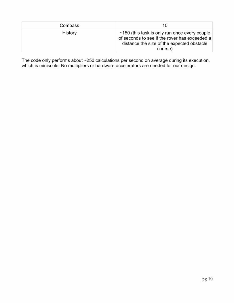
Compass 10
History ~150 (this task is only run once every couple of seconds to see if the rover has exceeded a
distance the size of the expected obstacle course)
The code only performs about ~250 calculations per second on average during its execution, which is miniscule. No multipliers or hardware accelerators are needed for our design.
pg 10

4. Bill of Materials
Item Price Location & Datasheet Image
Altera DE0 Nano FPGA Board
$59.00(academic)
http://www.digikey.com/catalog/en/partgroup/cyclone-iv-de0-
nano-evaluation-board-p0082/18846
http://www.terasic.com.tw/cgi-bin/page/archive.pl?
Language=English&CategoryNo=165&No=593&PartNo=4
Pololu 12V, 131:1 Gear Motor w / 64
CPR Encoder
x2
$39.95x2
http://www.robotshop.com/ca/pololu-gear-motor-encoder-
1447.html
Pololu 37D mm
Motor Bracket pair
$7.95 http://www.pololu.com/catalog/product/1084
Pololu Wheel 80x10m pair
$9.25 http://www.pololu.com/catalog/product/1434
pg 11

Dagu Ball Caster $2.75 http://www.robotshop.com/productinfo.aspx?pc=RB-Dag-
21&lang=en-US
Universal mounting hub pair for 6mm
shafts
$7.95 http://www.pololu.com/catalog/product/1083
Sharp IR Sensors
20-150 cmx3
$14.95x3
https://solarbotics.com/product/35235/
https://content.solarbotics.com/products/datasheets/sharp
_gp2y0a02yk.pdf
LSM303DLHC 3D Compass and
Accelerometer Carrier with
Voltage Regulator
$19.95 https://www.sparkfun.com/products/10703
http://www.sparkfun.com/datasheets/Sensors/Magneto/LSM303%20Datasheet.pdf
pg 12
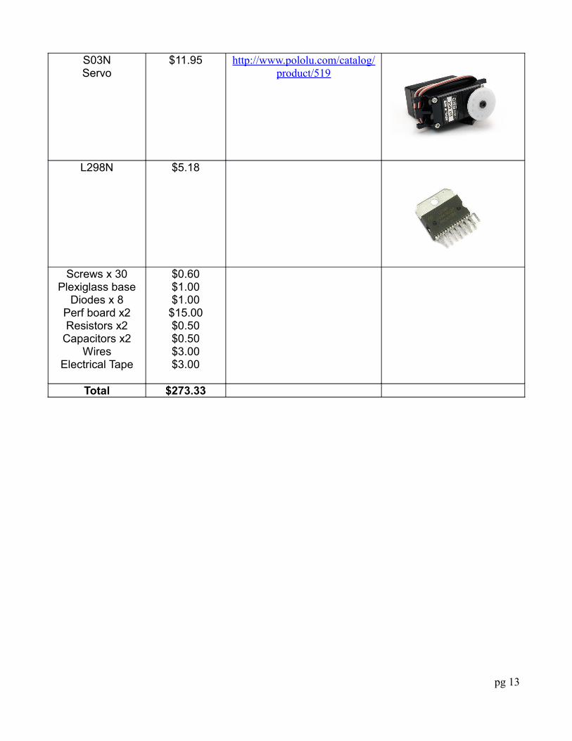
S03NServo
$11.95 http://www.pololu.com/catalog/product/519
L298N $5.18
Screws x 30Plexiglass base
Diodes x 8Perf board x2Resistors x2
Capacitors x2Wires
Electrical Tape
$0.60$1.00$1.00$15.00$0.50$0.50$3.00$3.00
Total $273.33
pg 13

5. Reusable Units
Unit Performance Size
DE0-Nano SOPC Demo Code and IP Cores from
Altera Corporation
Fast and reliable, good base for projects
6.11 MB
PWM Module: g1 iOS RC Car 2012 Application Notes [1]
Fast, works as expected 4 KB
LSM303DLHC code base [2] Could not get it working. Code is bloated to support
other LSM303 models
8 KB + 5 KB
OpenCores I2C Controller [5] Not tested. According to online sources, it runs well
once the initialization hurdle is passed
300 KB
pg 14

6. Datasheet
Performance
The robot is configured to detect objects 7cm to 35cm in front of it, upon detection, the robot will stop and check its left/right sensors & memory for what path to travel down next. The battery life of the robot using rechargeable AA NiMH batteries is approximately ~2 hours. Usage past this time is not recommended as there might not be enough power for the DE0 or the motors won't have enough power to travel at full speed (12V).
Operating Conditions
The three wheeled rover is designed to run indoors and on flat surfaces. The sensitivity of the exposed wiring means that collisions can seriously damage the robot and prevent further correct operation. The robot only looks forward on a horizontal plane so it does not have edge detection; do not run the robot on tables or on raised surfaces!
IO Table
Signal Type Voltage & Current Drawn
Origin & Pin Number
Destination & Pin Number
DE0 Nano Power Supply
Off-Board Electronics
3.6-5.7 VDC500mA
AA Battery Packs DE0 Nano 2-Pin External Power Header
2-PIN Power Header
Sharp IR Sensor Power
Off-Board Electronics
4.5V to 5.5V33mA
AA Battery Packs Sharp IR Sensor
Vcc
Sharp IR SensorAnalog Outputs
Off-Board to Board
N/A Sharp IR Sensor Voltage Output
Vo
DE0 Nano GPIO_2 2x13 Header
Analog_In1Analog_In3Analog_In5
LSM303DLHC Power
Board to Off-board
2.16V to 3.6V DE0 Nano GPIO_0 Header
VCC3P3 (PIN 29)
LSM303DLHC Power
Vdd
LSM303DLHCSCL
Board to Off-board
N/A DE0 Nano GPIO_0 Header
LSM303DLHC SCL
pg 15

GPIO_010 (PIN_B6)
SCL_A 24
LSM303DLHCSDA
Board to Off-board
N/A DE0 Nano GPIO_0 Header
GPIO_011 (PIN_A6)
LSM303DLHC SDA
SDA_A 25
DE0 Nano PWM Signal Generator
FPGA Board N/A PWM component on FPGA
DE0 Nano GPIO_0 Header
GPIO_00 (PIN_D3)GPIO_01 (PIN_C3)GPIO_02 (PIN_A2)GPIO_03 (PIN_A3)
Servo Power Off-board electronics
~5V300mA
AA Battery Packs Servo
Servo Control Signal
Board to Off-board
N/A DE0 Nano GPIO_0 Header
GPIO_018(PIN_E7)
Servo
H-Bridge PWM Input Signals
Board to Off-Board
N/A DE0 Nano GPIO_0 Header
GPIO_00 (PIN_D3)GPIO_01 (PIN_C3)GPIO_02 (PIN_A2)GPIO_03 (PIN_A3)
L298N
INPUT 1 (PIN 5)INPUT 2 (PIN 7)INPUT 3 (PIN 10)INPUT 4 (PIN 12)
Motor Power Off-Board Electronics
6V to 12V250mA to 300mA
12V AA Battery Packs
Motor Power
Red & Black wires
Motor Encoder Power
Off-Board Electronics
3.5V to 20V AA Battery Packs Motor Encoder Power
Vcc (Blue wire)
Motor Encoder Output Readings
Off-Board to Board
N/A Motor Encoder Output
Encoder A output (Yellow)Encoder B output(White)
DE0 Nano GPIO_0 Header
GPIO_04 (PIN_B3)GPIO_05 (PIN_B4)GPIO_06 (PIN_A4)GPIO_07 (PIN_B5)
pg 16

Power Requirements
By using multimeter measurement, we obtained the following values:
Component Voltage Current
DE0 Nano 5V ~500mA
Sharp Infrared Sensors 5V 30mA each
S03N Servo 5V 120mA
LSM303DLHC Compass 3.3V 10mA
1 Motor 14.9V 300mA
Motor Encoders 5V ~40mA
pg 17

7. Background Reading
http://ieeexplore.ieee.org/xpl/articleDetails.jsp?tp=&arnumber=4681422
This report describes the design of an autonomous robot with IR sensors. The design differed slightly in that they used a PIC micro-controller and the motor driver was the L293D, instead of the L298N that we're using. In the report, they describe the logic to avoid obstacles, which could be helpful in designing our software. When an obstacle is detected, they first reverse slightly before executing a turn. Since our robot is a rectangular shape, turning could cause the corners to come in contact with the detected wall, so reversing should be implemented.
http://ieeexplore.ieee.org/xpl/articleDetails.jsp?tp=&arnumber=5599642 - FPGA based multiple-output PWM pulse generator. Provided us with insight on how to create PWM on the Cyclone IV
http://www.robot-electronics.co.uk/acatalog/I2C_Tutorial.html – Tutorial on I2C, explains the protocol and master/slave relationship.
http://www.pololu.com/blog/10/force-and-torque – Brief explanation on the basics of torque [3]
pg 18

8. Test Plan
Software
The main hardware-independent software component that needs to be tested is the PWM module. To do this, we can compile the project and connect a GPIO pin (acting as a PWM generator) to an oscilloscope. By changing duty cycle in code, we can verify the PWM functionality.
Hardware
SDRAM: SDRAM can be tested by running a program similar to the ECE492 Lab 2 code where memory addresses are read/written. Memory allocation of megabytes in memory with malloc can also be used to test capacity.
Flash: To test flashing onto the DE0 Nano, we can simply load sample program like “Hello World”. We then turn off the board and turn it back on, if the program still runs then flash worked.
H-Bridge circuit with motors: Voltmeters and ammeters will be used on all components and parts of the circuit to make sure the proper voltage and current is fed to each part of the circuit. This is obviously necessary to make sure our components don't explode and the operation is as expected. When the H-bridge is verified, we can connect the motors and test if the motors speed up, slow down, or reverse based off the PWM signals sent to the H-bridge inputs.
Motor Encoders: When the motors are powered, we connect the encoder outputs to GPIO pins on the DE0 and read the output to see if the shaft rotated the expected number of times. Speeding up or slowing down of the motors should be reflected in the encoder output.
LSM303DLHC Compass: SDAT line from the compass is read to see what the compass reading for different directions. We can compare to external compass readings to measure the accuracy of the LSM303DLHC.
Sharp IR Sensors: IR sensors will be tested by measuring the feedback as we place objects in front of the sensor. If the object detection is correct within the range of 20-150cm, then we know it is working within specification. Error testing will also be done, such as seeing the detection accuracy for low-light and high-light conditions.
S03N Servo: Tested by sending different rotation values and running over a long period of time. Since for our operation, the servo will be rotated at fixed values (left, center, right), if the servo rotates to the same positions every rotation cycle, operation is correct.
pg 19

System Integration
After assembly, we can test multiple components at once, such as telling the robot to travel a certain distance and seeing if the IR detection and compass readings are correct. If the robot avoids obstacles successfully, navigating logic is verified. We can set up multiple boxes in a course and see if the rover can avoid multiple objects and navigate around them without getting stuck in a loop.
pg 20

9. Experimental Results and Characterization
For unit testing, we found our IR sensors to return the expected values in code for the distances we placed objects in front of the sensor. The IR sensors are very accurate and we had to make sure any objects placed in front of it were directly in front of the sensor or else it would miss the object.
Motor encoders returned the expected square waves (in oscilloscope) corresponding to input voltage. Maximum speed (12V) would increase wave frequency while minimum voltage (6V) would decrease frequency.
Servo operation is set to rotate left and right 30 degrees to detect obstacles that on the sides in front of the rover. Through calibration, we found duty cycles of about +/-10% will achieve this required rotation.
Initially, our H-bridge circuit did not work. After extensive testing and consultation with TAs, we determined the IC chip wasn't fully inserted in the board, and the sensor pins were improperly grounded. After checking connections, the circuit functioned as expected. However, as the rover travels forward, we noticed the left motor goes slightly faster than the right motor. Eventually it starts tilting and not travel in a straight line anymore. To fix this, the left motor's duty cycle is slightly smaller the right's duty cycle to even them out.
We do not tell the motors to go at full speed during operation. Right motor duty cycle is set to 90% and left motor duty cycle is ~87%. This allows the rover more time to react to objects and makes debugging faulty operation a lot easier.
System integration testing was successful. When an obstacle is detected by the front sensor, the motors stop and navigation logic is run to see whether it turns left, right or goes in reverse. Obstacle avoidance is successful, but the compass module is not functional. Since compass readings cannot be used, encoder readings are use to approximate turns using hard-coded encoder counts, but that proved to not be accurate all the time. Sometimes turns would be slightly off and not perfectly 90 degrees.
We set up multiple boxes in a course and the rover can avoid multiple objects and navigate around them without getting stuck in a loop. When a dead end is reached, the rover reverses and travels to the next free path. Since the IR sensors were mounted on the edges of the base, when the rover is extremely close to an object, it cannot properly detect it (low voltage is returned) and will travel into it. The obstacle course must be properly spaced out to avoid this scenario.
pg 21

10. References
[1] http://www.ece.ualberta.ca/~elliott/ece492/appnotes/2012w/PWM/
[2] https://github.com/pololu/LSM303/blob/master/LSM303/LSM303.cpp
[3] http://www.pololu.com/blog/10/force-and-torque, internet, last accessed Feb. 4, 2013 (used for information regarding torque. Final calculations are our own)
[4] http://www.sharpsma.com/webfm_send/1487
[5] http://alterawiki.com/wiki/OpenCores_I2c
[6] CPU processor, SDRAM, I2C, ADC SPI Controller cores and C base code provided by Altera
pg 22

11. Appendix
11.1. Quick Start Manual
(1) Place rover at beginning of maze(2) Turn on DE0-Nano battery pack, and wait a few seconds for program to run(3) Turn on sensors/servo battery pack, then flip the motor switch to “ON”(4) Turn everything off in reverse order when maze complete
(5) Note: If motors aren't running, and servo is moving, confirm motor switch is set to “ON”, and try tilting and gently shaking the base
11.2. Future Work
Remote control using Xbee modulesInitially we had planned for both autonomous operation of the robot with no user input and then remote control over WiFi using Xbee modules to send and receive commands. The user would control the movement of the robot using the WASD keys on a keyboard, sent through the UI of a desktop program. Due to time constraints, this functionality was not implemented for the final version.
Better bodyThe wiring appears messy, and the motors we purchased are much more powerful than what is expected of them. We could upgrade to a metal frame, and cover the top so the circuitry is more contained.
Edge DetectionCurrently, our rover is limited to a 2D maze strictly with walls. To make our rover capable of completing more complex mazes, such as slopes and edges, a downward facing IR sensor could be added to implement edge detection.
CompassWe were not able to fully implement the compass module. In future work, the compass could be implemented so sense of direction, angled turning, and 3D mapping would be possible.
pg 23

11.3. Hardware Documentation
11.3.1. Hardware Block Diagram
pg 24

11.3.2. Robot Schematic
pg 25

11.3.3. H-Bridge Circuit
pg 26

11.3.4. Hardware Wiring Diagram
pg 27

11.3.5. Obstacle Course Diagram
pg 28

11.3.6. Navigation Logic Block Diagram
pg 29

11.4 Source Code
Source code repository: https://github.com/pghu/g14_threewheeledrover
Notable Source Code Index:
Verilog/VHDL:
toplevel.v: Top level file for the robot PWM.vhd: Pulse width modulation module, modified from 2012 g01 iOS robot application noteencoder.vhd: Used to read encoder readings, modified from PWM.vhd codeservo.vhd: Used to rotate the servo, modified from PWM.vhd code
C Source Code ( /software/ROVER/ ):
nav.c : Contains tasks for reading from ADC, encoders, compass, PWM control, and main navigation loop control
main.c : Debug code to test modules individually
/lib/robot_includes.h : Main header file for library inclusions and constant definitions
/lib/motors.c : Function library for using motors, and examining travel history
/lib/LSM303.c: Modified code from Pololu for initializing and reading from the LSM303DLHC
pg 30