Embed Size (px)
Citation preview

External Use
TM
Three-Phase Power Meter
Solution
FTF-SEG-F0475
M A Y . 2 0 1 4
Hui Ding | Field Application Engineer

TM
External Use 1
Session Objectives
• Understand electricity meter block diagram and major functionalities.
• Familiarize with Kinetis M series MCUs, Photon features for metering
application.
• Familiarize with Freescale 3PH AFE reference designs, HW/SW
development tools and algorithms offering.
• Understand the components selection to guarantee meter accuracy,
how to improve meter EMC performance.
• Understand meter calibration steps.

TM
External Use 2
Agenda
• Introduction to Electricity Metering
• Kinetis M Series MCUs
• Electricity Metering Algorithms
• Three-phase AFE Reference Design
• Power Meter Design-Accuracy
• Power Meter Design-EMC
• Power Meter Design-Calibration
TM
External Use 3
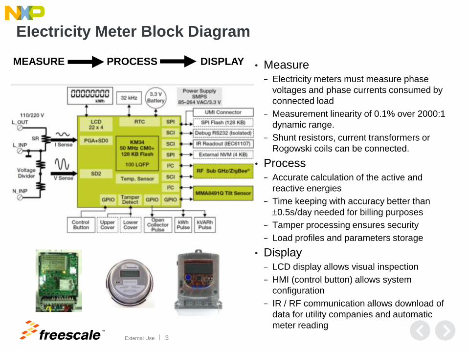
Electricity Meter Block Diagram
• Measure − Electricity meters must measure phase
voltages and phase currents consumed by
connected load
− Measurement linearity of 0.1% over 2000:1
dynamic range.
− Shunt resistors, current transformers or
Rogowski coils can be connected.
• Process − Accurate calculation of the active and
reactive energies
− Time keeping with accuracy better than
0.5s/day needed for billing purposes
− Tamper processing ensures security
− Load profiles and parameters storage
• Display − LCD display allows visual inspection
− HMI (control button) allows system
configuration
− IR / RF communication allows download of
data for utility companies and automatic
meter reading
MEASURE PROCESS DISPLAY
TM
External Use 4
Agenda
• Introduction to electricity metering
• Kinetis M series MCUs
• Electricity metering algorithms
• Three-phase AFE reference design
• Power meter design-accuracy
• Power meter design-EMC
• Power meter design-calibration

TM
External Use 5
Core
• CM0+ core Up to 50MHz
• Separate FLL post-scalers for Flash and Core
clocks.
• Dedicated PLL for ΣΔ modulator clock
• 4ch DMA
• Memory Protection Unit
• Single 32kHz Crystal operation
• MHz Crystal optional
Security & Encryption
• Programmable 16/32-bit CRC
• IRTC w/ tamper detection
• 3 Tamper pins (operating on battery)
• Random Number Generator (NIST: SP800-90)
• AES Encryption (via software library)
• Memories
• Up to 128 KB Program Flash
• 16 KB SRAM
Analog
• 4x24 bit ΣΔ after averaging (2xPGA) highly
accurate supporting EN 50470-1, EN 50470-3,
IEC 62053-21, IEC 62053-22 and IEC 62053-23,
optimized for shunt sensor (≥50uOhm).
• 0.1% error in active and reactive energy over a
dynamic range of 2000 to 1
• Internal 1.2V reference voltage (33 ppm/oC)
• 12-ch 16-bit SAR for auxiliary measurement
• 2x analog comparator
Serial Communications
• 2x SPI
• 4x UART
• All combined with Quad Timer & HSCMP for IR
• 2 support ISO7816
• All support flow control
• 2× I2C
• All UARTs and SPIs are 3V compatible while 1
UART and 1 SPI are both 3V and 5V compatible
(open drain configuration)
Peripheral XBAR
• Remapping peripheral IOs
• UART selection for IR
GPIO • Up to 68 with push pull, pull up/down select • Up to 8 GPIO with filter • Support for interruption on any edge • Single cycle access for all GPIOs (Rapid GPIO)
Power Modes & Clock
• Many low power modes supported • 2.7V to 3.6V Operating voltage with AFE • 1.71V to 3.6V Operating voltage without AFE • 1.71V-3.6V IRTC VBAT supply • 32kHz or 4 MHz internal clock source • 32.768kHz crystal oscillator
Package
• 100 LQFP, 64 LQFP and 44 LGA options • -40°C ~ +85°C Temp
Timer/PWM/Clock
• Quad Timer (total 4 universal timers)
• 2x PIT
• 1x Watchdog Timer (windowed, independently
clocked)
• 1x EWM (External Watchdog Monitor)
• 1x LPTimer
LCD Display
• Up to 288 segment LCD, up to 8 backplanes
Wakeup Unit
• Group selected GPIOs (16), LPTIM, RTC
(+tamper pins) , HSCMP, SCI , Brownout and
POR sources to wake up from Power Gated
STOP mode
Kin
eti
s M
seri
es M
CU
s O
ne P
ag
er
IPs with functionality
specific to metering
+/-250mV analogue I/O
pads with 6kV PESD
x3

TM
External Use 6
Analogue Subsystem (Overview)
Kinetis M
SD
SD
PGA+SD
PGA+SD Phase shifter &
Decimator
Phase shifter &
Decimator
Phase shifter &
Decimator
Phase shifter &
Decimator
MUX 16-bit SAR
ADC
SD3
SD2
SD1
SD0
ADC0
ADC1
ADC2
1.2V VREF VREF
2x HSCMP ADC11
……..
}{XBAR
1.2V Voltage Reference
• Generates accurate
reference voltage shared
between PGA, SD ADC,
SAR ADC and HSCMP
16-bit SAR ADC
• Conversion speed up to
818 ksps
• 12 single ended channels
• 4 result registers
• variety of triggering options
24-bit SD ADC and PGA
• Conversion speed up to
101 ksps on four channels
• Four SD ADC channels
(two PGA)
• SW and HW triggering
High-Speed Comparator
• Two comparators, each with
• 6-bit DAC to provide selectable
voltage reference
• Accepts a +/-250mV input signal
range
Inter-peripheral Crossbar Switch
• Allows programmable digital
interconnections between
specific modules
• 33 input x 33 output multiplexer
• Interrupt or DMA request
Phase Shifter and Decimator
• Phase shift compensation with
resolution of 0.003o @ 50 Hz
line frequency
• Capability to connect external
galvanic ally isolated SD
modulators
Kinetis M analogue and digital blocks allow
realization most of electricity meter use-cases.
TM
External Use 7
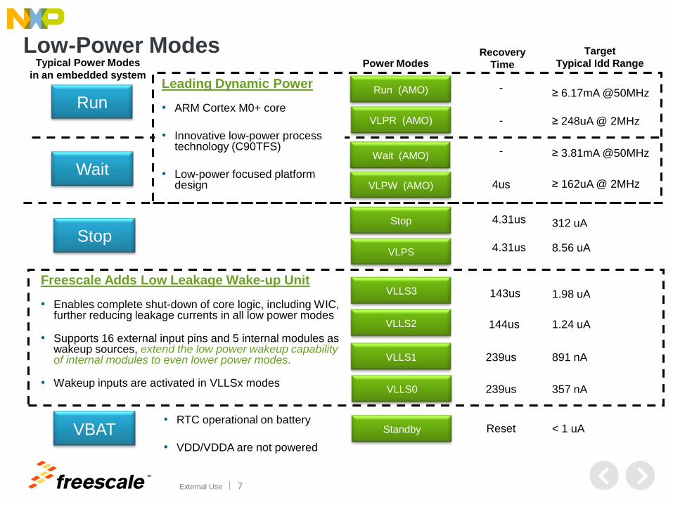
Low-Power Modes Power Modes
Run (AMO)
VLPR (AMO)
Wait (AMO)
VLPW (AMO)
Stop
VLPS
VLLS3
VLLS2
VLLS1
Recovery
Time
Target
Typical Idd Range
-
-
-
≥ 6.17mA @50MHz
4us
4.31us
4.31us
143us
144us
239us
1.98 uA
1.24 uA
891 nA
312 uA
8.56 uA
VLLS0 357 nA 239us
Freescale Adds Low Leakage Wake-up Unit
• Enables complete shut-down of core logic, including WIC, further reducing leakage currents in all low power modes
• Supports 16 external input pins and 5 internal modules as wakeup sources, extend the low power wakeup capability of internal modules to even lower power modes.
• Wakeup inputs are activated in VLLSx modes
Run
Wait
Stop
Typical Power Modes
in an embedded system Leading Dynamic Power
• ARM Cortex M0+ core
• Innovative low-power process technology (C90TFS)
• Low-power focused platform design
VBAT • RTC operational on battery
• VDD/VDDA are not powered
Standby < 1 uA Reset
≥ 248uA @ 2MHz
≥ 3.81mA @50MHz
≥ 162uA @ 2MHz

TM
External Use 8
Kinetis M Series MCU Advantages for Electricity Metering
Needs Kinetis M Solution
Computation Lowest power Cortex-M0+ core (32x32 multiply in 1 cycle) up to 48MHz.
Low Power Less than 124.4uA/MHz VLPR Current1
Down to 357nA @VLLS0 (POR disabled)2
Low Power Boot with less then 2.33mA peak current3
User Interface Up to 4x40 (8x36) segment LCD driver operating in all low power modes.
Communication Up to 4 UARTS, 2 SPIs and 2 IIC.
Memory
Scalability
From 64 KB to 128 KB of Flash.
16 KB of RAM
Program longword execution time (65us)
Time Keeping Auto compensated RTC with high speed calibration, 5 ppm accuracy, 0.88 ppm resolution of the
1Hz pulse output and operating in all low power modes.
Analog
Modules
Highest linearity and resolution AFE with 4x24bit SD with 92 dB SNR
Low VREF gain drift over temperature of 33ppm/oC
Combined gain temperature drift of the PGA, SD ADC and Internal 1.2 VREF blocks (150ppm/oC)
High Speed 16-bit SAR ADC and CMP.
Security Passive and active tamper pins.
Random Number Generator (NIST: SP800-90)
Robustness I/O pads withstanding 4 kV ESD and 6 kV PESD
1) Typ. 248.8uA @ 2 MHz core, system, bus clock, and 1 MHz flash clock. MCG configured for BLPE mode. All peripheral clocks disabled. 2) If independent RTC including 32 kHz oscillator operates then device consumes additional 1.3uA from VBAT terminal. 3) Measured for 1.7ms linear supply voltage ramp with 3.26 V steady-state value; main function executed in 4.1 ms from applying supply voltage.

TM
External Use 9
Kinetis M Series MCU Selection for Electricity Metering
Part Number
Package LCD Drive
Features Target APP 24 bit ƩΔ
ADCs
number
AUX ADC (Flash /
SRAM)
MKM14Z64CHH5 4
44LGA
- 64 / 16 KB
5ppm RTC integrated,support harmonics function,
cover 1PH/2PH/3PH meter
design
1PH/2PH/3PH
AFE/harmonics analyzing
chip/smart plug/power
monitor
16 bit (5x5mm2
)
poMKM14Z128CHH5 4 16 bit
44LGA
- 128 / 16 KB
5ppm RTC integrated,support harmonics function,
cover 1PH/2PH/3PH meter
design
1PH/2PH/3PH
AFE/harmonics analyzing
chip/smart plug/power
monitor
(5x5mm2
)
MKM33Z64CLH5 3 16 bit 64LQFP 8 x 17 64 / 16 KB
5ppm RTC and LCD drive
integrated,support
harmonics function, cover
1PH/2PH/3PH meter design
Low cost 1PH/2PH/3PH SOC
power meter
MKM33Z128CLH5 3 16 bit 64LQFP 8 x 17 128 / 16 KB
5ppm RTC and LCD drive
integrated,support
harmonics function, cover
1PH/2PH/3PH meter design
Low cost 1PH/2PH/3PH SOC
power meter
MKM33Z64CLL5 3 16 bit 100LQF
P 8 x 38 64 / 16 KB
5ppm RTC and LCD drive
integrated,support
harmonics function, cover
1PH/2PH/3PH meter design
Low cost 1PH/2PH/3PH SOC
power meter
MKM33Z128CLL5 3 16 bit 100LQF
P 8 x 38 128 / 16 KB
5ppm RTC and LCD drive
integrated,support
harmonics function, cover
1PH/2PH/3PH meter design
Low cost 1PH/2PH/3PH SOC
power meter
MKM34Z128CLL5 4 16 bit 100LQF
P 8 x 38 128 / 16 KB
5ppm RTC and LCD drive
integrated,support
harmonics function, cover
1PH/2PH/3PH meter design
Low cost 1PH/2PH/3PH SOC
power meter

TM
External Use 10
Agenda
• Introduction to electricity metering
• Kinetis M series MCUs
• Electricity metering algorithms
• Three-phase AFE reference design
• Power meter design-accuracy
• Power meter design-EMC
• Power meter design-calibration

TM
External Use 11
Freescale Algorithms for Electricity Metering
• Electricity meter vendors require algorithms supporting calculations that
adhere to either IEC/MID or ANSI C12 standards.
• Freescale offers algorithms that calculates metering quantities in either
time or frequency domain
An algorithm must be seen to be believed. - Donald Knuth
Filter-based metering algorithm
• processes signals in time
domain
• leverages IIR filters
• based on elementary 32/64-bit
fractional arithmetic
FFT-based metering algorithm
• processes signals in frequency
domain
• leverages DFT computation
• based on elementary 32/64-bit
fractional arithmetic

TM
External Use 12
• Executes when power meter is supplied from the mains
• Uses high-pass and low-pass IIR filters
• Hilbert filter is used for computing reactive power and energy
• Software configuration tool is available to setup structure, filter coefficients, and generate C-header file.
• Active energy counter updated at every calculation step.
For more information see AN4265
0 1 2 3 4 5 6 7
0 1/Fs
X
Calculation step
where: “Fs” is sampling frequency
“D3” is decimation ratio calculated as D1-D2+1
“N” is order of the Hilbert Transformation Filter.
Filter-based Metering Algorithm – Block Diagram

TM
External Use 13
FFT Metering Algorithm – Block Diagram
• Number of samples (N) must be power-of-two (32,64,128,etc.)
• Ensures that processed samples represent full signal period
• Use linear interpolation technique to generate exactly power-of-two samples on a metering device with SD ADC for entire signal period.
• Sampling frequency must be at least 2x or higher than the maximum frequency included in input signal.
For more information see AN4255 and AN4847
Where:
“N” is number of samples
“RE” is real part of the vector
“IM” is imaginary part of the vector

TM
External Use 14
Complex power (in Cartesian form) is defined as :
12
1
12
1
)()()()()()()()()()()()(
N
k
IMREREIMIMIMREREIMRE
N
k
IMRE kIkjUkIkjUkUkIkUkIkjUkUkjIkI
Real part of complex power:
Active power Imaginary part of complex power:
Reactive power
FFT Metering Algorithm - Computation
Root Mean Square computing (in Cartesian form) is defined as :
Where: IRE(k),URE(k) are real parts of k-th harmonics of input current/voltage
IIM(k),UIM(k) are imaginary parts of k-th harmonics of input current/voltage
12
1
22 )()(
N
kIMRE kIkIRMSI
12
1
22 )()(
N
kIMRE kUkURMSU

TM
External Use 15
Agenda
• Introduction to electricity metering
• Kinetis M series MCUs
• Electricity metering algorithms
• Three-phase AFE reference design
• Power meter design-accuracy
• Power meter design-EMC
• Power meter design-calibration

TM
External Use 16
Three-Phase AFE Reference Designs
Based On Kinetis KM14/KL36 MCUs
Features
• 5 to 60A current range (Ib =5A,Imax=60A)
• 135 to 600V, 50/60 Hz voltage range
• Accuracy class: active power 0.5S, reactive power 2S
• 5ppm accuracy RTC over full temp range(-40~110℃)
• Hardware line frequency measurement
• Various low-power modes applicable for metering
• 8x32 segment LCD
• tamper meter cover monitoring with time stamp
• infrared hardware interface & 2 Isolated RS485 port
• LED pulse outputs (KWH, KVAH, MFUNC)
• Isolated electrical pulse outputs (KWH, KVAH, MFUNC)
• Xtrinsic 3-axis low power tilt sensor for electronics tamper detection (optional)
• Various external memory interface(EEPROM,Flash)
• Cost effective two layer PCB board & BOM
• EMC proven design (ESD ± 15kV, EFT ± 6KV)
Software provided
• Application framework, Filter-based metering algorithms, FFT metering algorithms (optional)
44 LGA
5 x 5 mm2
TM
External Use 17
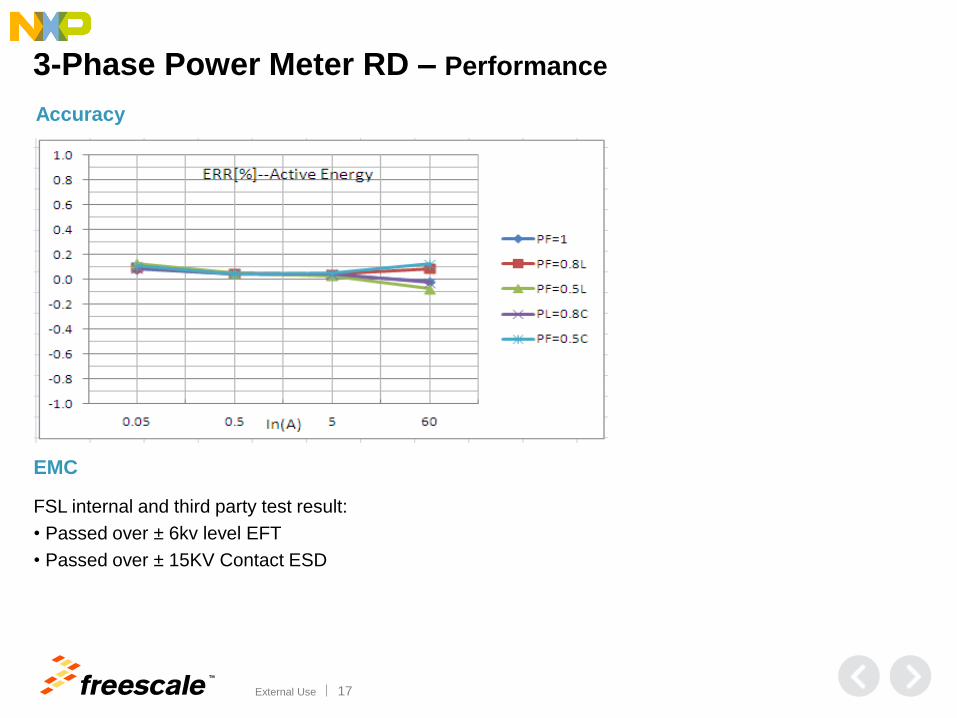
Accuracy
EMC
FSL internal and third party test result:
• Passed over ± 6kv level EFT
• Passed over ± 15KV Contact ESD
3-Phase Power Meter RD – Performance

TM
External Use 18
3-Phase Power Meter RD – Resource Cost
Resource Usage(3PH) Flash RAM CPU loading CAL Period
Filter 34KB 4.3KB 75% 1200Hz
FFT(interpolation)
N=64
29KB 8KB 70% 50Hz
FFT(synchronous)
N=64
22KB 5KB 51% 50Hz
TM
External Use 19
Agenda
• Introduction to electricity metering
• Kinetis M series MCUs
• Electricity metering algorithms
• Three-phase AFE reference design
• Power meter design-accuracy
• Power meter design-EMC
• Power meter design-calibration

TM
External Use 20
Meter design key point-accuracy
1 Current sensor
1.1 Shunt
• power capacity
Should met the power capacity requirement under max current and sample signal
threshold under min current. • temp drift
Should consider the temp drift affect overall meter accuracy under full temp.
1.2 CT/PT
• power capacity
Ib/Imax should be considered to meet the metering voltage/current limit.
• ratio
Ratio should be considered between sensor’s original and second sides.
• accuracy
CT/PT accuracy standard is critical for phase error and amplitude error. 1.3 Rogowski Coil
• Provides electrical isolation, could handle higher current.
• No DC or high current saturation and immune to magnetic tampering.
• Interference (far field) pickup - limited by design or shielding.

TM
External Use 21
Meter design key point-accuracy
2 Sampling circuit
2.1 R/C filter
• Hardware RC filter cut off frequency should be considered avoid higher frequency noise
input to ADC ports.
• For differential SD ADC, should consider a stable common mode point, usually the
common point is the system ground.
2.2 Resistor divider
•Temp drift of resistor is one key factor , it will directly impact the meter accuracy under
full temp.
•Accuracy under normal temp is another factor which should be consist to meter
calibration condition.
2.3 Sampling wirings
•Sampling wirings is quite critical to limit the noise coupling and channel crosstalk to
guarantee the input signal integrity.
2.4 Protection circuit
•Do consider the affection of protection circuit leakage to the meter accuracy.

TM
External Use 22
Meter design key point-accuracy
3 Power supply
3.1 AC/DC
• AC/DC power supply quality such as ripple situation will affect DC supply directly.
• Keep safe distance between AC/DC and the MCU system.
3.2 DC/DC or LDO
• Both DC output will put into MCU VDD/VDDA directly, it will impact the MCU whole
system noise level.
3.3 ADC VREF
•ADC VREF is the voltage reference to ADC, it could be MCU internal generated one or
external one.
•ADC VREF performance will impact the ADC result directly, hence affect the metering
accuracy.

TM
External Use 23
Meter design key point-accuracy
4 ADC performance
Operation
Mode
PGA Signal range (mV peak-peak)
SNR (dB @ OSR=2048)
Current (mA)
Normal ON 31 (gainx32) 64 (74) 4.0
Normal OFF 1000 92 1.4
4.1 24bit SD ADC
4.2 16bit SAR ADC
TM
External Use 24
Meter design key point-accuracy
5 Metering algorithm
5.1 Filter based algorithm
• Includes high-pass and low-pass IIR filters to calculate RMS.
• Includes Hilbert filter for computing reactive power and energy.
• Includes configurable coefficients used in typical metering case.
• Higher metering accuracy without harmonics function.
5.2 FFT algorithm
• Both synchronous and asynchronous sampling technique can be used in FFT algorithm
calculation. • The harmonics times depends on the CPU loading and sampling logic.
•Sampling frequency must be at least 2x or higher than the maximum frequency
included in input signal.
•Guaranteed metering accuracy with harmonics function.
TM
External Use 25
Agenda
• Introduction to electricity metering
• Kinetis M series MCUs
• Electricity metering algorithms
• Three-phase AFE reference design
• Power meter design-accuracy
• Power meter design-EMC
• Power meter design-calibration

TM
External Use 26
Meter design key point-EMC
1 Auxiliary power supply
1.1 Power Supply Class
• Resistive and capacitive power supply.
• Switch Mode Power Supply.
• Industry Frequency Transformer Power Supply.
1.2 Advantage & Disadvantage
• Industry frequency transformer power supply is most favorable for getting better EMC
performance, the disadvantage is it’s bigger volume and lower voltage dynamic range.
• Resistive and Capacitive power supply is the most economic one, but it has limitation for the
power load and most serious EMC challenge.
• Switch mode power supply is the trend for using in power meter, should choose fit
components and assure good PCB layout to guarantee EMC performance.

TM
External Use 27
Meter design key point-EMC
2 PCB layout
• Keep the layout in the right order: power ->GND->signal.
• Keep every signal line has GND in parallel especially the long wiring.
• Keep the bottom and top area under the MCU has relative overall GND plane.
• Keep all the components has safe distance away from the board edge.
• Keep all the VDD/VDDA power domain star connection and has decoupling/buck capacitor.
• Avoid putting vias between bypass capacitor and MCU pins.
• Avoid no obvious current flow back loop.
• Avoid VDD/VDDA routing without through decoupling/buck capacitor.
• Avoid no enough space between isolation parts.
2.2 Avoid
2.1 Keep
TM
External Use 28
Meter design key point-EMC
3 Protection circuit
3.1 R/C
R/C is the most cost effective components for improving EMC performance.
3.2 TVS
TVS should be considered to the terminal lines and VDD/VDDA supply close
the board edge etc.
3.3 NTC
NTC should be used in series of lines to limit the current in EMC sensitive
case.
3.4 Diodes
Diodes to VDD or GND could be used for EMC sensitive lines such as sampling
circuit .
3.5 Bead/inductor
LC circuit is also one of the most effective way for improving EMC performance.
TM
External Use 29
Meter design key point-EMC
4 MCU
4.1 MCU design
MCU silicon design is also critical for getting better EMC performance.
4.2 MCU clock
MCU clock configuration is effective for getting better EMC performance.
4.3 MCU pin configuration
Pins unused suggest to configured to be GPIO output to improve EMC performance.
4.4 MCU /RESET
/RESET pin EMC performance is lower than normal pins, configure it to be GPIO output can
improve whole system EMC performance.

TM
External Use 30
Agenda
• Introduction to electricity metering
• Kinetis M series MCUs
• Electricity metering algorithms
• Three-phase AFE reference design
• Power meter design-accuracy
• Power meter design-EMC
• Power meter design-calibration

TM
External Use 31
Meter design key point-Calibration
1 Put meter on the calibration instrument
2 Set the calibration load value, example 220V,5A, PF 0.5L, then power up the board;

TM
External Use 32
Meter design key point-Calibration 3 Download the binary file, then run image
4 Wait 45S for calibration finished, parameters automatically stored into flash

TM
External Use 33
Designing with Freescale
Tailored live, hands-on
training in a city near you
2014 seminar topics include
• QorIQ product family update
• Kinetis K, L, E, V series MCU product training
freescale.com/DwF

TM
© 2014 Freescale Semiconductor, Inc. | External Use
www.Freescale.com