Embed Size (px)
Citation preview
Hongxia Yu1*, Zhicheng Chen2
1 School of Information Science and Engineering, Shenyang University of Technology, Shenyang, China. 2 Department of Control Theory and Control Engineering, Shenyang University of Technology, China. * Corresponding author. Tel.:18624047512; email: hongxia7512@ 163.com Manuscript submitted July 10, 2014; accepted January 19, 2015. doi: 10.17706/ijcce.2015.4.3.204-210
Abstract: The DTC-SVPWM scheme is a kind of high performance control scheme of induction motor drives
to improve the high torque ripple drawback of conventional DTC. SVPWM has two PI controllers which are
used to generate the reference stator voltage vector. However it is difficult to adjust the parameters of PI
controller due to the complexity of the control system. The self-tuning PI fuzzy controller was proposed to
adjust the PI parameters in this paper. Two inputs of the fuzzy controller are torque or flux error and error
change rate. Correction coefficients of proportional and integral are outputs. The simulation results show
that the proposed method can significantly reduce the torque ripple and is suitable for various motor at
different working state.
Key words: DTC, fuzzy controllers, induction motor drive, SVPWM.
1. Introduction
Among all control methods for induction motor drives (IMD), direct torque control seems to be particularly
interesting being independent of machine rotor parameters. In the last years DTC has become a popular
technique for three-phase IMD as it provides a fast dynamic torque response and robustness under machine
parameter variations without the use of current regulators [1]–[3]. The major disadvantage of the DTC drive
is the steady state ripples in torque and flux [4]. A torque ripple analysis since none of the inverter switching
vectors is able to generate the exact stator voltage required to produce the desired changes in torque and flux,
torque and flux ripples compose a real problem in DTC induction motor drive [5]. The most common solution
to this problem is to use space vector modulation depends on the reference torque and flux. In DTC-SVPWM,
the PI controllers substitute by the hysterics comparators [6]. A fast torque response with low torque ripple
for this SVM-DTC is significantly improved with a constant switching frequency compare to classical DTC In
[7] proposes a neuro-fuzzy based SVM technique for voltage source inverter and its performance is
compared with the conventional based SVM and Neural Network based SVM methods. This scheme is
five-layer network, receives the d-axis and q-axis voltages information at the input side and generates the
duty ratios as an output for the inverter circuit. In [8] the fuzzy PI speed controller has a better response for
a wide range of motor speed. In [9] it is designed a Takagi-Sugeno fuzzy controller to substitute flux and
torque PI controllers in a conventional DTC-SVM scheme. Flux error after fuzzy controller generates d axis
component of the reference voltage vector, torque error after PI regulator generates q axis component of the
reference voltage vector, fuzzy control is widely used in direct torque control system, and the superiority of
its robust has been showed in [10].
International Journal of Computer and Communication Engineering
204 Volume 4, Number 3, May 2015
Three-Phase Induction Motor DTC-SVPWM Scheme with Self-tuning PI-Type Fuzzy Controller

In this paper an adaptive fuzzy PI controller along with the SVPWM technique is applied to inverter. Fuzzy
PI controller is used to achieve precision torque control and minimize torque ripple. When fuzzy logic is used
for the on-line tuning of the PI controller, it receives fuzzy values of the torque error and change of torque
error. Its output is updating in the PI controller gains based on a set of rules to maintain excellent control
performance. The proposed technique is simulated in simulink to validate the performance of the algorithm.
2. Basic Control Principles
2.1. DTC-SVPWM Principles
The proposed DTC-SVPWM system is shown in Fig. 1. Three PI controllers are used for processing speed,
torque and flux errors. Speed error is processed through the speed PI controller to generate torque
reference.
w*
PI controller dq
to
αβ
vq
vd
Vα
Vβ
θ
SVMvd
Inverter
ABC toα β
vdiα uαiβ uβ
FluxTorque θ
estimator
ψ *ψ
Inductionmotor
w
PI
PI
Te*
Te
Fig. 1. Proposed DTC-SVPWM model.
The role of torque and flux PI controllers is to generate the command voltages dU and qU respectively.
Induction motor stator flux is not easy to measure directly, so we measure voltage and current values of
stator side to obtain the value of the stator flux. It calculates the value of estimated electromagnetic torque Te
using (1). After calculating and Te, they are compared with their reference values * and *Te
respectively. The controllers generate the components of command voltage in a synchronous reference frame
aligned to the stator flux. SVPWM unit receives the command voltage and impress the desired voltages to the
motor using a voltage source inverter. In the synchronous reference frame voltage equations can be written
as (2) and (3). The output of the PI flux and torque controllers can be interpreted as the reference stator
voltage components dU , qU are the stator flux oriented coordinates (d-q), converted these d-q coordinate
components to α-β components (4).
2( )
3s s s sTe p i i (1)
*I
d P S S
KU K
S
(2)
*ITq PT e e
KU K T T
S
(3)
International Journal of Computer and Communication Engineering
205 Volume 4, Number 3, May 2015
cos sin
sin cos
d
q
UU
UU
(4)
2.2. SVPWM Calculation Unit
The accuracy in calculation of dU , qU is very important as they are used to generate inverter gating
pulses such that direct torque and flux control for the induction motor drive achieved with minimum torque
ripple [11]. SVPWM need to know the reference voltage vector in which sector, in order to use the adjacent
basic voltage vector to synthesis. According to a given reference voltage component U , U , using Table 1
we can determine refU the number of sector.
Table 1. Sector Number and SVPWM Switching Time N 1 2 3 4 5 6
Sector II VI I IV III V
1T Y -X Z -Y -Z X
2T -X Z Y -Z X -Y
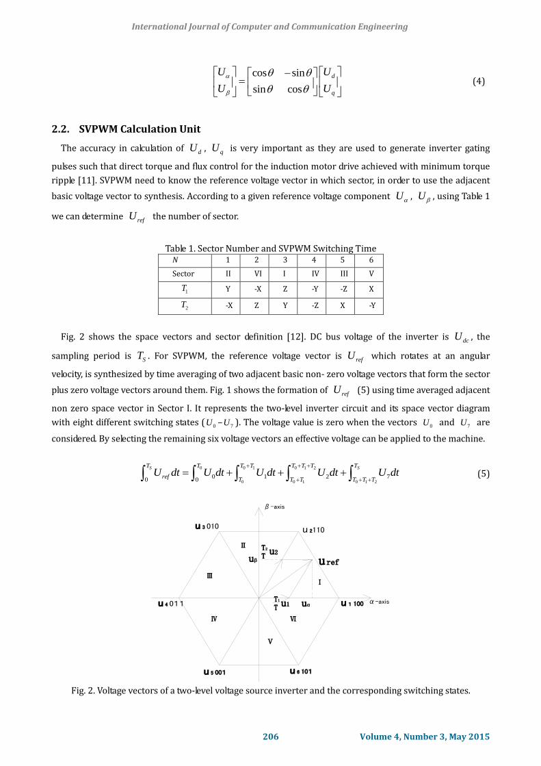
Fig. 2 shows the space vectors and sector definition [12]. DC bus voltage of the inverter is dcU , the
sampling period is ST . For SVPWM, the reference voltage vector is refU which rotates at an angular
velocity, is synthesized by time averaging of two adjacent basic non- zero voltage vectors that form the sector
plus zero voltage vectors around them. Fig. 1 shows the formation of refU (5) using time averaged adjacent
non zero space vector in Sector I. It represents the two-level inverter circuit and its space vector diagram
with eight different switching states (0U –
7U ). The voltage value is zero when the vectors 0U and
7U are
considered. By selecting the remaining six voltage vectors an effective voltage can be applied to the machine.
0 0 1 0 1 2
0 0 1 0 1 20 1 2 7
0 0
S ST T T T T T T T
refT T T T T T
U dt U dt U dt U dt U dt
(5)
u 2110u 3 010
u 4 011
u 5 001 u 6 101
u 1 100
β-axis
α-axis
Ⅲ
Ⅳ Ⅵ
Ⅴ
Ⅱ
uβ
uαT1
T u1
Ⅰ
u ref
T2
Tu2
Fig. 2. Voltage vectors of a two-level voltage source inverter and the corresponding switching states.
International Journal of Computer and Communication Engineering
206 Volume 4, Number 3, May 2015
3. Design of Fuzzy PI Controller
In this section DTC-SVPWM strategy is proposed using modified fuzzy logic controllers. In order to
improve direct torque control system dynamic and static performance, the torque and flux is adjusted by the
adaptive fuzzy PI controller. The structure of torque and flux controller is the same, so we only specify the
torque controller. According to the analysis of step-response in DTC system, four fields of the fuzzy variables
could be defined as following. The field of the motor torque feedback error TE is [-3, 3], the field of torque
error variation E is [-3, 3], and the field of value kp , ki is [-3, 3]. The input membership functions use
Gaussian functions, output membership functions use triangular functions. Error and rate of error change is
inconsistent with the scope of the fuzzy controller field, so we use conversion factors transforming them into
the field of the standard variable. kp, ki are the adjusted proportional and integral value, kp’, ki’ are the initial
choice of proportional and integral value, kp , ki is proportional and integral correction factors. All the
fuzzy subsets are {NB, NM, NS, ZE, PS, PM, PB}. The abbreviations, NB, NM, NS, ZE, PS, PM, PB, represent the
negative big, negative small, negative medium, zero, positive small, positive medium, and positive big,
respectively. Each rule of the fuzzy controller can be described with TE , E , kp and ki . As shown in
Table 1, if TE = NB and E = NB, then kp = PB and ki = NB. There are 49 rules with two input
variables. The fuzzy control rules are expressed in Table 2 and Table 3.
Table 2. Fuzzy Logic Control Rules of kp
E E
NB NM NS ZO PS PM PB
NB PB PB PM PM PS ZO ZO
NM PB PM PM PS ZO ZO NS
NS PM PM PM PS ZO NS NS
ZO PM PM PS ZO NS NM NM
PS PS PS ZO NS NM NM NM
PM PS ZO NS NM NM NB NB
PB ZO ZO NM NM NB NB NB
Table 3. Fuzzy Logic Control Rules of ki E
E NB NM NS ZO PS PM PB
NB NB NB NM NM NS ZO ZO
NM NB NB NM NS NS ZO ZO
NS NB NM NS NS ZO PS PS
ZO NM NM NS ZO PS PM PM
PS NM NS ZO PS PS PM PB
PM ZO ZO PS PS PM PB PB
PB ZO ZO PS PM PM PB PB
4. Simulation Results
We used different dynamic operating conditions such as: no load sudden change in the speed reference
(from 0 s to 1 s), step change in the motor load (from time 1.6 s to 2.5 s). From time 1.0 s to 1.6 s the
reference torque is 800Nm, from time 1.6 s to 2.0 s the reference torque is 1000Nm, from time 2.0 s to 2.5 s,
International Journal of Computer and Communication Engineering
207 Volume 4, Number 3, May 2015
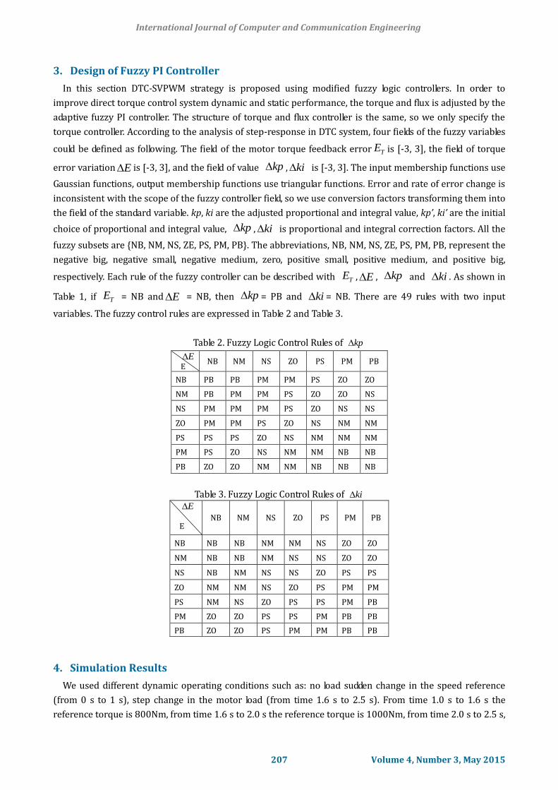
the motor reference torque is 600Nm. Here generated torque is always follows reference torque, at this time
induction motor speed is follow as reference speed (500 r/min), it shows in Fig. 3. All the test results showed
the good performance of the proposed DTC-SVM scheme with fuzzy PI controllers. In Fig. 3(a) it can be seen
that the speed returns to its reference quickly when the external load changes, exhibiting strong robustness
against external load disturbance and minimizing torque ripple.
0 0.5 1 1.5 2 2.5-200
0
200
400
600
800
1000
1200
time
Te
Electromagnetic Torque
Time
(a)
0 0.5 1 1.5 2 2.5-200
0
200
400
600
800
1000
1200
time
Te
Time
(b)
Fig. 3. (a) Results of electromagnetic torque (149.2KW motor) of classical DTC-SVPWM. (b) Electromagnetic
torque of DTC-SVPWM with fuzzy PI controllers.
0 0.2 0.4 0.6 0.8 1 1.2 1.4 1.6 1.8 2480
485
490
495
500
505
510Rotor speed
(a)
0 0.2 0.4 0.6 0.8 1 1.2 1.4 1.6 1.8 2480
485
490
495
500
505
510
(b)
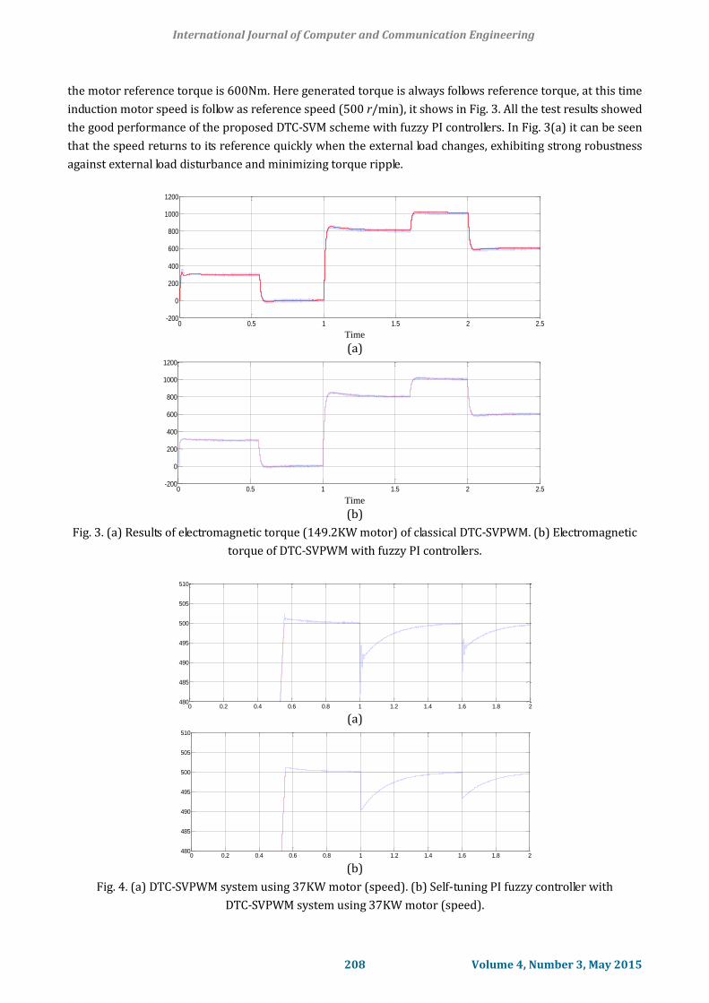
Fig. 4. (a) DTC-SVPWM system using 37KW motor (speed). (b) Self-tuning PI fuzzy controller with
DTC-SVPWM system using 37KW motor (speed).
International Journal of Computer and Communication Engineering
208 Volume 4, Number 3, May 2015
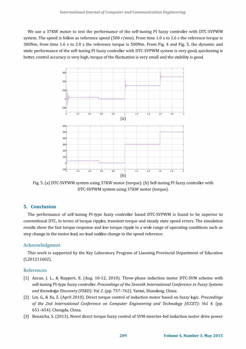
We use a 37KW motor to test the performance of the self-tuning PI fuzzy controller with DTC-SVPWM
system. The speed is follow as reference speed (500 r/min). From time 1.0 s to 1.6 s the reference torque is
300Nm, from time 1.6 s to 2.0 s the reference torque is 500Nm. From Fig. 4 and Fig. 5, the dynamic and
static performance of the self-tuning PI fuzzy controller with DTC-SVPWM system is very good, quickening is
better, control accuracy is very high, torque of the fluctuation is very small and the stability is good.
0 0.2 0.4 0.6 0.8 1 1.2 1.4 1.6 1.8 2
-200
0
200
400
600
Electromagnetic Torque
(a)
0 0.2 0.4 0.6 0.8 1 1.2 1.4 1.6 1.8 2-100
0
100
200
300
400
500
600
(b)
Fig. 5. (a) DTC-SVPWM system using 37KW motor (torque). (b) Self-tuning PI fuzzy controller with
DTC-SVPWM system using 37KW motor (torque).
5. Conclusion
The performance of self-tuning PI-type fuzzy controller based DTC-SVPWM is found to be superior to
conventional DTC, in terms of torque ripples, transient torque and steady state speed errors. The simulation
results show the fast torque response and low torque ripple in a wide range of operating conditions such as
step change in the motor load, no-load sudden change in the speed reference.
Acknowledgment
This work is supported by the Key Laboratory Program of Liaoning Provincial Department of Education
(L201211602).
References
[1] Azcue, J. L., & Ruppert, E. (Aug. 10-12, 2010). Three-phase induction motor DTC-SVM scheme with
self-tuning PI-type fuzzy controller. Proceedings of the Seventh International Conference in Fuzzy Systems
and Knowledge Discovery (FSKD): Vol. 2. (pp. 757–762). Yantai, Shandong, China.
[2] Lin, G., & Xu, Z. (April 2010). Direct torque control of induction motor based on fuzzy logic. Proceedings
of the 2nd International Conference on Computer Engineering and Technology (ICCET): Vol. 4. (pp.
651–654). Chengdu, China.
[3] Benaicha, S. (2013). Novel direct torque fuzzy control of SVM-inverter-fed induction motor drive power
International Journal of Computer and Communication Engineering
209 Volume 4, Number 3, May 2015
engineering. Proceedings of the Fourth International Conference on Power Engineering: Energy and
Electrical Drives (pp. 340–345).
[4] Jagan, R. M. (2010). DTC-SVM of induction motor with three level diode clamped inverter. Technical and
Non technical International Journal VSRD-TNTJ, 1, 178–187.
[5] Jagan, M. R. M., & Manthi, M. D. (November 2013). Two fuzzy logic controllers based DTC-SVM of
induction motor. International Journal of Engineering Research & Technology, 2(11), 1956–1969.
[6] Belkacem, S., Naceri, F., & Abdessemed, R. (April 2011). Improvement in DTC-SVM of AC drives using a
new robust adaptive control algorithm. International Journal of Control Automation and Systems, 9,
267–275.
[7] Durgasukumar, G., & Pathak, M. K. (June 2012). Comparison of adaptive neuro-fuzzy-based space-vector
modulation for two-level inverter. International Journal of Electrical Power and Energy Systems, 38(1),
9-19.
[8] Toufouti, R., Meziane, S., & Benalla, H. (June 2006). Direct torque control for induction motor using fuzzy
logic. Advances in Ceramic Science and Engineering Journal, 6(2), 265–270.
[9] Jos e, L., Azcue, P., Alfeu, J., & Sguarezi, F. E. (2010). Ts fuzzy controller applied to the DTC-SVM scheme
for three-phase induction motor. Proceeding of Power Electronics Conference (COBEP) (pp. 201–206).
Praiamar, Brazil.
[10] Aimer, A. F., Bendiabdellah, A., & Miloudi, A. (2009). Application of fuzzy logic for a ripple reduction
strategy in DTC scheme of a PWM inverter fed induction motor drives. Journal of Electrical Systems, 1,
13–17.
[11] Subba, R. G. (2013). Vector controller based speed control of induction motor drive with 3-Level SVPWM
based inverter. International Journal of Emerging Trends in Electrical and Electronics, 1(4), 1–11.
[12] Sandeep, N. P., Vishal, S. S., & Akshay, A. P. (2013). Simulation analysis of SVPWM inverter fed induction
motor drives. International Journal of Emerging Trends in Electrical and Electronics, 2(4), 18–22.
Hongxia Yu was born in Shenyang, Liaoning province, China, in 1975. She received the
BSc degree from Liaoning Institute of Technology in 1998, the MSc degree from
Northeastern University in 2003. Then she received the PhD degree from Shenyang
Institute of Automation, Chinese Academy of Science in 2012. Her fields of interest are
state monitor and control of induction motor, etc. She has been as a lecturer in Shenyang
University of Technology since 2003.
Zhicheng Chen was born in Harbin, Heilongjiang province, China, on April 28, 1988. He
received his undergraduate degree in automation from City Institute of Dalian University of
Technology, Dalian, China, in 2011. He is currently working toward the master degree at
the Shenyang University of Technology, Shenyang, since 2012. His scientific work is related
to electrical machines and drives. His current research interest includes direct torque
control of induction motors.
International Journal of Computer and Communication Engineering
210 Volume 4, Number 3, May 2015


![PI CONTROLLER BASED SHUNT CONNECTED THREE ...realize the potential and feasibility of PI controller [17], [18]. (a) Current Wave of Current Controller (b) Current Controller Waveform](https://img.dokumen.tips/doc/110x75/604b4b4b953f6a233834072a/pi-controller-based-shunt-connected-three-realize-the-potential-and-feasibility.jpg)


![Pi Pid Controller[eBook.veyq.Ir]](https://img.dokumen.tips/doc/110x75/577cd44b1a28ab9e789821ba/pi-pid-controllerebookveyqir.jpg)