Embed Size (px)
Citation preview
THREE DOLLARS A YEAR THIRTY CENTS A COPY - GENERAL ELECTRIC
e VOL. 34, NO. 4 APRIL, 1931
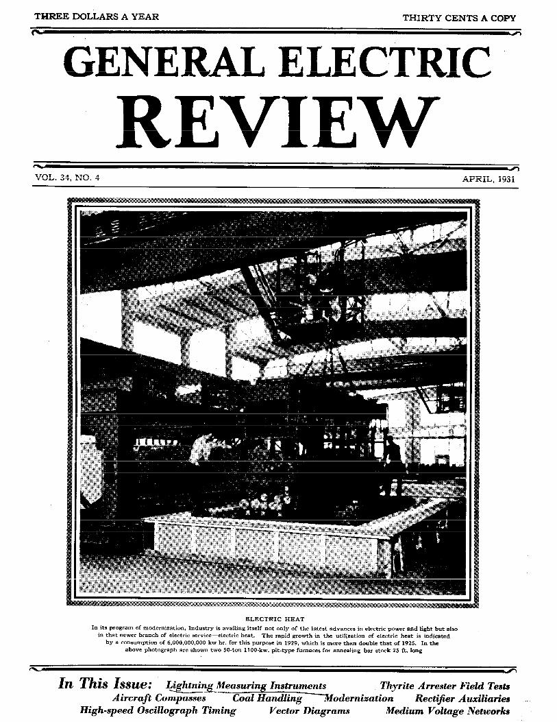
ELECTRIC HEAT i n its program of modernlzatlon, Industry IS avalllng ltself not only of the latest advances in electric power and light but also
in that newer branch of electr~c service--electric heat. The rapid growth in the utilization of electric heat 1s indicated by a consumption of 6,000,000,000 kw-hr. for this purpose in 1929, which is more than double that of 1925. In the
above photograph are shown two 50-ton 1100-kw. pit-type furnaces for annealing bar stock 25 ft. long
In This Issue: @ghtni% Measuring Instruments Thyrite Arrester Field Tests Aircraft Compasses Coal Handling Xodernization Rectifier Auxiliaries ~
High-speed Oscillograph Timing Vector Diagrams Medium Voltage Networks

1 = r instruments for Lightning Measurements -
C7 u
Latest Developments and Applications of Surge-voltage Recorders-Cathode-ray Oscillographs- Lightning-stroke Recorders-Surge Indicators-Lightning-severity Meter
By C. M. FOUST General Engineering Laboratory, General Electric Company
C ONSTANTLY increasing demands for unin- terrupted service on transmission lines has focussed attention upon the most disturbing
factor-lightning. The problem simply stated is : "How may transmission lines and protective equip- ment be arranged to avoid tripouts and loss of power due to lightning flashover of the line insulation?" Progress toward the solution of this problem has until recent years been greatly hindered through lack of sultable measuring instruments. For a iong time, sphere gaps and needle gaps were the only measuring devices of practical importance for such purposes and these devices have obvious limitations which narrowed their usefulness on actual power lines. Within the past few years, however, intensified effort has resulted in the design and application of various surge-measur- ing instruments, through the use of which a great amount of engineering information concerning light- ning surges has been gathered. Present progress justi- fies the belief that the continued use of these devices will result in a solution to the lightning problem.
Classification of Instruments
Surge-measuring instruments suitable for lightning surges must record within microseconds (millionths of a second) and must be of such nature that auto-
matic registration is obtained. The uncertainty of the time of occurrence of electrical storms and lightning strokes necessitates instruments that are ever in readiness for operation. The short time elements involved militate against the use of movable parts in the instruments; and the devices described in this article will therefore depend for their operation upon rather unusual electrical principles.
For the purpose of presenting a summary of the present available instrur~ie~iis, Table I has been arranged.
Surge-voltage Recorder
The surge-voltage recorder is built in both the moving-film and stationary-film type of instrument. Both types utilize the Lichtenberg figure method of registration of crest surge voltage and their voltage- figure size calibrations are the same. The instruments are single phase and are equipped with direct and reversed-polarity electrodes connected in parallel. This arrangement permits the registration of each surge voltage regardless of polarity with both a posi- tive and negative Lichtenberg figure.
The measuring range of the instrument is 3 to 30 kv., giving a ten-to-one ratio between the highest point on the calibration scale and the initial registration
TABLE I
Name of Instrument
Surge-voltage recorder (moving-film type)
Surge-voltage recorder (stationary-film type)
Cathode-ray . oscillograph
Lightning-stroke recorder
Surge indicator
Lightning-severity meter
Quantity Measured
Crest voltage
Crest voltage
Wave shape and amplitude
Indicates direct stroke to tower
Indicates insulator flashover
Integrates field intensities a t time of lightning strokes
Method of Connection
Capacitance coupling
Capacitance coupling
Capacitance coupling
S'nunted across tower or ground wire
Shunted across to.wer or ground wlre
Small antenna
Method of Registration
Lichtenberg figures on photographic film
Lichtenberg figures on photographic film
Cathode-ray on photographic film
on photographic film
Disruptive link trips target
Glow tube illumination on photographic film
Direct 1 Instrument
Range Time Scale (Kilovolts)
3-30' I % in. per hr.
None
2 and above I
0-l*
None
None
Microseconds (millionths of a set-
* By the use of a suitable voltage divider, the measurement range of these instruments can oi course be extended upward ior a transmission line of any voltage. Three million volts have been measured.
, 0"" ?I:" n o l 3-Y.3
I hT̂,,
I

236 April, 1931 GENERAL ELECTRIC REVIEW VO!. 34, Nc. 4
voltage. The use of the double-registration feature has great advantages for the following reasons:
(1). Because negative surge voltages up to approximately 2.5 times normal give negative Lichtenberg figures upon a directly connected recorder and on such a recorder are entirely ob- scured by the norma1,line voltage band.
Surge-voltage Recorder (Moving-film Type)
The moving-film type. of surge-voltage recorder is shown in Figs. 1 and 2. An earlier design has been previously described. ( I ) The present instrument has been improved in two respects, first in the design of the enclosing box and second in the method of time registration. The insulating box has been rearranged to provide a fixed compartment for the clock mecha- nism and a hinged cover for the photographic-film compartment. The advantages obtained are protec- tion to the clock and definite alignment of the hinged cover.
The voltage-figure size calibration is shown in Fig. 3. This calibration holds for both the moving-
Fig. 1. Surge-voltage Recorder of the Moving-film Type, Shown with the Film and Clock Compartments Open
(2). Because negative Lichtenberg figure sizes are dependent upon the rate of voltage rise to a much greater degree than the positive'figures..
(3). Because the availability of both figures for all high-voltage surges permits more accurate determination of the nature of the surge producing the figures.
Fig. 3. Voltage Calibration of Surge-voltage Recorder. Showing Relation of Positive Lichtenberg Figure
Size to Crest Value of Surge Voltage
Fig. 2. Moving-film Type of Surge-voltage Recorder, Shown with the Clock Compartment Open and
the Film Compartment Closed
film and stationary-film types of surge-voltage recorder.
A specimen field record from the moving-film type of instrument is shown in Fig. 4. I t will be noted that the time markings are very clearly printed on the center of the film and that the serial number of the instrument appears above the hour of 12 midnight. -, I nls . time marking is accompiished through engraved numbers filled with radioactive r~iaieriai on the driv- ing dmm and has been fmsd ta be very satisfactory. Edge-light fog which frequently occws due tc! lc!c!se!y rolled films will not cover the time scale. Fig. 4 shows about ten inches of the seven-foot record obtained for each weekly exposure. The clock drives the film j.i in. per hour or 1 f t . per day and will drive it satisfactorily for eight days.
(1)"Measurement of Surge Voltages on Transmission Lines Due to Lightning, by E. S. Lee and C. M. Foust. GENERAL ELECTRIC REVIEW. March. 1927. pp. 135-145.

iNSTRUMENTS FOR LIGHTNING iviEASUREiv1Eiu'TS 237
-. rleid insraiiarions and Records n - t - ~ - - 4- +hA + . ~ . , : ~ ~ l e,.vmo-T,n ltnw0 ,.opn,-a n t x c r r u l g agaul IAJ ulrj by ylral OWL 5"- vrvu6v A v,vrv
in Fig. 4, the black parallel lines below and above the timing marks are normal voltage lines on the directly connected and reversed recorder respectively and are obtained from the normal excitation of the circuit. The Lichtenberg figures a t about 2:15 a.m. indicate a surge voltage of negative and unidirectional polarity,
,,A ,L,..+ +,, +;,,,. nnrmnl Trnlflc,p ThP cmallpr allu a u w u c 1.~11 u l r u r o u v r ~ r ~ u l LAUU v vSYYbV. ---- figure tc! the right indicates a surge voltage of two times normal voltage. Fig. 5 shows a typical instal- lation of the moving-film type of surge-voltage recorder with the instrument sheltered in the standard metal housing and mounted in the tower structure; and Fig. 6 shows an installation with the instrument on a ground pole..
Fig. 4. Transmission-line Lightning-surge Record Made by a Surge-voltage Recorder of the Moving-film Type
Fig. 5. Typical Installation of Moving-film Type of Surge-voltage Recorder on a Transmission-line Tower
The connection of the surge-voltage recorder to the transmission line is made through a very low capaci- tance by means of an insulator-string voltage divider with grading shields as shown in Fig. 7. If all the dimensions are adhered to within reasonable limits, the arrangement can be used on lines of various voltage ratings by selecting a suitable number of insulator units. Table I1 gives values for various line voltages.
TABLE I1
I
Rating of Line Sumber of Voltage (Kilovolts. Insulator Units Divider
Phase Voltage) Ratlo
This type of voltage divider has been given a thorough trial over several years' operation and has been productive of satisfactory results.

238 April! 1931 GENERAL. ELECTRIC REVIEW IT-1 Y "I. 34, NO. 4
A thorough study of surge voltages on a trans- mission line necessitates the installation of a number of recorders spaced along the line a t intervals of a few miles between each. Such an installation will furnish a voltage profile such as that shown in Fig. 8. From this profile may be calculated an
in which e =voltage in kilovolts a t distance s from 01
Eo = crest voltage a t origin of surge K = a factor depending on the particular line
ranging from 0.0004 to 0.00006 s = distance in miles from origin of surge.
To Lme
t
Fig. 6. Typical Installation of a Surge-voltage Recorder of the Fig. 7. Installation Arrangement of a Moving-film Type of Moving-film Type on a Ground Pole Beside a Surge-voltage Recorder and Insulator-string Voltage Divider,
Transmission-line Tower and the Connections to a Transmission Line and Ground
2520
2 540
2160 T
I380 + laao n $ 1620 .- 5 I440 0 ,O 1260
loeo
3 900
# 720
--U 540 3 160
180
'0 5 10 15 20 25 30 35 40 45 50 55 60 65 70 Miles
Fig. 8. Profile of the Crest Surge Voltage as a Lightning Surge Travels Along a Transmission-line Conductor. ' This profile is plotted from the records =C surge-vdt=ge recorders inj:a::+d aioiip ih= iine
attenuation curve for the surge as it travels from the point of disturbance.
A great amount of vaiuabie information has been gathered with this technique on various systems. The analysis of these data has resulted in the development of an empirical formula c 2 ) as follows:
e = Eo KsEo+ 1
(?)"Lightning Investigations on Transmission Lines " by W. W. Lewis and C. M. Foust. GENERAL ELECTRIC REVIEW. ~ a r c h . ' l 9 3 0 , pp. 185-108.
rigin
and
This formula has been checked by applying surges from an artificial-lightning generator and the agree- ment is within the limits of accuracy of the testing equipment.
In addition to attenuation data, valuable informa- tion on amplitude of surge voltages and frequency of occurrence of surges has also been obtained. (2) Surge voltages of 14 times normal crest voltage to ground (2400 kv. on 220-kv. line) have been measured but these are few in number. At the lower voltage

INSTRUMENTS FOR LIGHTNING MEASUREMENTS 239
amplitudes, the mirnbsr of surges inciaeases rapidly. At two or three times normal voltage, surges are usually as frequent as 100 per lightning season. It must be kept in mind, however, that a t low ampli- tudes i t is difficult to differentiate between switching and lightning surges.
Surge-voltage Recorder (Stationary-film Type)
Progress in lightning measurements soon demon- strated that a smaller and lower-cost instrument
Fig. 9. Surge-voltage Recorder of the Stationary-film Type
entirely eiidosed i ~ i a porcelain housing which makes a thoroughly weatherproof instrument. The supporting brackets may be readily bolted to the cross arm of a tower and the lower portion of the porcelain housing when unlatched swings downward to permit with- drawal of the film box containing the exposed film and the insertion of another film box containing an unexposed film.
Each film box has a serial number engraved and filled with radio-active material so that the number is marked on every film exposed in that recorder. Speci- men records of films from this surge-voltage recorder are shown in Fig. 11.
Fig. 10. Stationary-film Type of Surge-voltage Recorder with the Porcelain Housing and Film Container Open
Fig. 11. Highly Damped Oscillatory Surge as Recorded by the Stationary-film Type of Surge-voltage Recorder
designed for use in the same field as the moving-film type surge voltage recorder was very desirable. Such an instrument is particularly applicable on distri- bution systems where it is necessary to obtain a number of measurements on the same pole or tower 2nd wherz the available space is 1i11lited. Figs. 9 and ?G shCnr a stat;Lsfiary-film tjrGe of -,t;rg~--;~ltage re- corder designed for use in this field.
This instrument has the same calibration character- istics as the moving-film type previously described. Two circular films four inches in diameter are placed one in each side of the insulating film box shown. The top film is in contact with the directly connected elec- trode and the bottom in contact with the reversed polarity electrode. As in the moving-film-type recorder, positive and negative Lichtenberg figures are obtained with each surge voltage applied. The film box is
For surge-voltage measurements above the range of the instrument, a capacitance voltage divider is desirable. Fig. 12 shows an arrangement of voltage divider and surge-voltage recorder which has a meas- uring range up to 200 kv. The voltage divider consists of two standard he-insuiator units mounted on the surge-voltage recorder, tile entire equipment beisg supprted sr, the recorder bracket arm. A por- celain protecting cap I s provided for the top insdatm unit. This cap insulates the hardware connected to the line and therefore makes the entire outfit proof against injury to the attendant.
A number of these instruments have been used during the past lightning season on distribution systems, and while a great amount of data has not as yet been collected the performance of the instru- ment has been satisfactory.

240 April, 1931 GENERAL ELECTRIC REVIEW Vol. 34, No. 4
Cathode-ray Oecillograph The fact that the electrons in the cathode-ray Laboratory experience with lightning generators stream can be deflected by voltage applied to small
early demonstrated that the time element or wave deflection plates simplified the application of the shape of the surge had an important bearing on cathode-ray oscillograph to a marked degree. A con- insulation failure. Therefore, in addition to the nection to the transmission conductor through a low
Fig. 12. Stationary-film Type of Surge-voltage Recorder with Capacitance Voltage Divider
for Measurements up to 200 kv.
Fig. 13. The 1928 Cathode-ray Oscillograph Transmission-line Lightning Laboratory
Fig. 14. The 1929 Cathode-ray Oscillograph Transmission-line Lightning Laboratory
measurement of the surge-voltage amplitudes of capacitance obtains ample energy for full-scale lightning surges on transmission lines, the determina- deflections; and by using insulators, similar to those tion of wave shapes became necessary. The cathode- of the normal line insulation, to serve as this capaci- ray oscillograph offered the only solution because the tance a thoroughly safe arrangement was obtained time elements involved are of the order of micro- without adding hazard to the line service. seconds and recording instruments with mechanically Figs. 13, 14, and 15 show cathode-ray oscillograph moving parts are too slow to trace such wave shapes. field laboratories for 1928, 1929, and 1930. In 1928

one Instrr~ment ~ 2 s rrced as s h a m in Fig. 16, and i= of this arrzngement which ~,rnefit attmtion. Thxmgh 1929 (Fig. 17) and 1930 (Fig. 18) two instruments the sensitive tripping gaps and circuits provided, the were used. The 1930 arrangement includes all progress first oscillograph begins to trace the wave shape in equipment and technique resulting from the previ- automatically within to 3/2 microsecond after the ous years' experience. For this reason, space will not incoming wave arrives on the transmission line con-
Fig. 15. The 1930 Cathode-ray Oscillograph Transmission-line Lightning Laboratory
Fig. 16. The Sinale Cathode-ray Oscillograph in the Lightning Laboratory of 1928. (See Fig. IS)
be taken here to describe the 1928 or 1929 arrange- ments.
The two oscillographs used in a 1930 lightning laboratory, and arranged as in Fig. 18, were con- nected in accordance with the diagram shown in Fig. 19. There are several particular operational features
ductor. This oscillograph then proceeds to record the lightning surge on a very fast time axis (50 micro- seconds full film width). The second oscillograph begins to trace the surge within 1 to 2 microseconds after the first instrument is in operation and records the remaining portion of the lightning surge and iater the reflections as the surge returns from the various points of transition along the conductor. Figs. 20 and 21 are typical examples of lightning surges obtained by t h e two-oscillograph method.
Continuous records of all lightning surges throughout a storm period are of course desirable. To make avail- able sufficient films for a great number of surges com-
ing in rapid succession, a special film ho!der was designed. This holder is shown in Fig. 22. The film holding compartment has been enlarged to permit the insertion of five 12-exposure roll films thus making possible 60 independent exposures.
Several hundred oscillograms have been obtained throughout the period of operation of the equipment. Specimens of oscillograms which have added mate- rially to the knowledge of wave shapes of lightning surges on transmission lines are shown in Figs. 23(a) to 23 (e), inclusive.
Lightning-stroke Recorder
Soon after the first measurements of voltage ampli- tude and wave shape of lightning surges were made, it became apparent that an instrument which would differentiate beb~ieer, the direct strokes to a transmis- sion tower, ground wire, or conductnr, Br?d the in- duced surges on a conductor would be of marked value.
This realization resulted in the design of the lightning-stroke recorder, which is an adaptation of the Lichtenberg figures for this purpose. This instru- ment is shown in Fig. 24. I t consists of a porcelain base which is securely fastened to a tower leg by a steel clamp, a weatherproof metallic cover, and a light-proof film packet. The porcelain base carries an electrode which is connected electrically to the

242 April, 1931 GENERAL ELECTRIC REVIEW Vol. 34, No. 4
1 3 T T supporting ciamp and the metallic cover holds an my flashed over. u11certai11 g rvu~~d pairvls and cvstiy electrode which is connected at a point on the tower climbing examinations have not resulted in accu- tower leg some 15 to 30 ft. above the instrument rate information concerning the location and number location. The film packet is placed between the of insulator assemblies that have been flashed over. electrodes. I n Fig. 6 a lightning-stroke recorder is shown mounted on and con- nected to the near leg of the tower.
A high-current surge (50,000 amp. or above), such as is associated with a direct stroke, gives ample voltage across the 15 to 30-ft. sec- tions of tower leg bridged by the instrument lead to result in a Lichtenberg fig- ure on the photographic films in the packet. The currents associated with in- duced surge voltages are not of sufficient magnitude to result in registrations on the instrument. In this way the lightning-stroke recorder when installed on each tower will indicate t h e locations of di rect strokes and will give an approximate value of surge current associated with each.
The Lichtenberg figures obtained on the films in the sealed light-proof packet do no t have t h e same characteristics as those obtained by surge-voltage recorders where the elec- trodes are in direct contact with the photographic emul- sion. However, laboratory tests have shown that close study of the lightning-stroke recorder films will permit the polarity of the recorded
4.- I.- A,.+,...-:-nA 5Ull;t;b L U UG UGlrGlllllllGU.
The cllf.rent-fir~re size cali- bration for this instrument is shown in Fig. 25, and a typical transmission-line direct-stroke record is shown in Fig. 26.
Surge Indicator
Fig. 17. The Two Cathode-ray Oscillographs in the Lightning Laboratory of 1929. (See F i g . 1 4 )
Fig. 18. The Two Cathode-ray Oscillographs in the Lightning Laboratory of 1930. (See F i g . 16)
To remedy this situation, a program of study and Transmission lightning studies have emphasized the test of several types of suggested devices was camed
need for a device which would give an immediate indi- out. As a result of this work, a surge indicator cation visible from thegroundwhen aninsulator assem- suitable for use as an indicator of flashovers on a

INSTRUMENTS FOR LIGHTNING MEASURE_M_ENTS V A ~ 'd L"
Fig. 23(a). First Cathode-ray Oscillogram of Lightning Surge on a Transmission Line. Taken a t Wallenpaupack July 27 1928 on phase Y. The superimposed oscillations are due io flasho;er on' an adja- cent phase
Fig. 19. Connection Diagram for the Automatic Operation of the Two Cathode-ray Oscillographs in the
Transmission-line Lightning Laboratory
Fig. 23(b). Cathode-ray Oscillogram Obtained on May 29.1929. Dead- end protective gaps a t this point flashed over on all three phases. This flashover caused a sharp change in voltage from 1260 kv. negative to 310 kv. positive in one microsecond. Flashover took place on the front of the wave
Fig. .20. Cathode-ray Oscillogram of the Voltage Variations During the First 50 Microseconds of a Lightning
Surge on a High-voltage Transmission Line
Fig. 23(c). Cathode-ray Oscillogram Taken on June 19. 1929. Record obtained while line was not enernized. Voltane was still rising a t the end of 36 microseconds and was then sudaenly reduced co zero. Subsequent examination of line insulation indicated a flashover 23 miles away, whlch appeared to correlate with this osc~llogram
Fig. 21. Oscillogram of the Voltage Variations During a '2200-Microsecond Period of a Lightning Surge on a
High-voltage Transmission Line
Fig. 22. Special 60-exposure Film Holder for Cathode-ray Oscillograph
Fig. 23(d). Cathode-ray Oscillogram Taken on July 19, 1929. This is a wave which has a sl~ghtly oscillatory nature and is typical of a large group of waves. A cloud-to-ground stroke was seen a t the instant this oscillogram was obtained. This stroke was a t least 10 miles distant from the laboratory and some distance from the line
Fig. 23(e). Cathode-ray Oscillogram Taken on July 24. 1930. The lightning stroke was within one tower span from the lightning laboratory
Fig. 23. Notable Cathode-ray Oscillograms

transmission-line insulator assembly was conceived and designed. This instrument is shown in Figs. 27 and 28. It consists of a weatherproof metal housing 8 in. in diameter and 295 in. thick, an indicating target, a frangible trip link, and a lead-in insulator. Fig. 27
(usually the tower arm) which carries the flashover current from a particular insulator assembly. Fig. 29 shows the location of the instrument and connecting lead for a transmission line of horizontal configuration and Fig. 30 for one of vertical configuration of con-
Fig. 24. Lightning-stroke Recorder Open to Show the Film Packet
Rad~Lx a / Par,f;rc F,pm - M#Ntmeftrs
Fig. 25. Calibration Curve of the Lichtenberg FigureSize and Tower Surge Current for the
Lightaiag-stroke Xecorder
Fig. 27. Surge Indicator with Frangible Link in Place and the Instrument Set in Readiness for Service
shows the instrument with link installed and the indicating target concealed. Fig. 28 shows the target indicating that a surge has passed (line-insulator units flashed over).
The surge indicator will operate satisfactorily when connected across a or ti on of the tower structure
Fig. 28. Surge Indicator with Target Showing. Thus Indicating That a Surge has Taken Place
ductors. I t will be noted that in each case the location of the instrument is such that it is readily accessible to the attendant near the main or upright structure of the tower. The tap lead extends along the tower arm and is connected to the iron of the tower at a point near the sumort for the insulator assemblv. This

INSTRUMENTS FOR LIGHTNING MEASUREMENTS 245
co~ir~eciing lead is securely fastened to the tower at each end and supported with sufficient insulators along its length to prevent the lead from falling on a live conductor and causing a line interruption.
Briefly, the instrument operates according to the following procedure: When the insulator assembly flashes over the rush of discharge current through the
Fig. 29. Schematic Diagram for Mounting Surge Indicators and Connecting Them to a Tower
Having Horizontally Arranged Conductors
instrument operation. The insertion of a new trip link, which is accomplished very readily, resets the instru- ment in readiness for another surge indication.
Fig. 31. Surge Indicator for Multiple-surge Indication, in Position That Indicates Two Surges
tower arm gives sufficient voltage across the instru- ment and the necessary follow-up current to disrupt the frangible link and allow the spring pressure to force the indicating target into the visible position.
Fig. 30. Schematic Diagram for Mounting Surge Indicators and Connecting Them to a Tower
Having Vertically Arranged Conductors
Fig. 32. Interior of the Surge Indicator Shown in Fig. 31
Some 1500 of these instruments have already been installed on transmission lines and very gratifying results have been obtained. A positive record of flash- over is obtained and the cost of tower climbing patrols - -
Power current from the line is not necessary for is materially reduced.

246 April, 1931 GENERAL ELECTRIC REVIEW Vol. 34, No. 4
r n r ~ I ne - suige iIidicator ilas lot.eI, in aI,ot~ier form for multiple-surge operation as shown in Figs. 31 and 32. This arrangement permits the insertion of five trip links and the indication of five surges without reloading.
Lightning-severity Meter
The instruments already described have all been designed for connection to the transmission line or tower and serve to obtain measurements or indica-
Fig. 33. Lightning-severity Meter
tions of surge conditions on the structure only. It is very desirable that some device be available which will serve to record the intensity of storm conditions to which the transmission line is subjected.
is a rneasure ui tiie i~liegrated fieid intensity over the period of exposure. The depth of exposure can be readily measured by photometric methods and an arbitrary but definite rating for storm severity obtained.
Several field installations of this device have been operated through the 1930 lightning season and the
Fig. 34. Instailation of Lightning-severity Meter and Antenna for Field Measurements
Fig. 35. Type of Record Made by the Lightning-severity Meter
To serve this purpose, the lightning-severity meter was produced. This instrument consists of a camera containing a photographic film, a glow lamp, and an antenna. Fig. 33 shows the instrument and Fig. 34 shows a field installation. Fig. 35 shows the type of record obtained.
TTTl . vv nen the anierma is withi~i tiie cloud field, i t obtains a charge proportional to thz s t rc~g th of that field. When the stroke t&es place, the field around the wire collapses and the antenna charge passes through the glow tube thereby producing a porpor- tional illumination which is recorded on the photo- graphic film. The depth of light exposure on the film
results obtained suggest that valuable information will be obtained through the future operation of this instrument.
Conclusion
The number of instruments recently designed and iiow '--- l:-l-'.-:.-- .-- availau~e lux- ~ i g ~ ~ ~ ~ ~ i x ~ g - s u r g e IIieasure- rnOrr+" hhn" nl*Onrlr7 *n".l..l+orl . Illblllra rraa a u r a u j rbauLubu 1:: marked improve- ment in the engineering understanding nf lightning phenomena. Through the continued use of these instruments, additional valuable data can be ob- tained and a final solution of the lightning problem reached.

Conclusion
The number of instruments recently designed and now available for lightning-surge measure- ments has already resulted in a marked improve- ment in the engineering understanding of lightning phenomena. Through the continued use of these instruments, additional valuable data can be ob- tained and a final solution of the lightning problem reached.