Embed Size (px)
Citation preview

. . . . . . . . . . . . . . . . . . . . . . . . . . . . . . . . . . . . . . . . . . . . . . . . . . . . . . . . . . . . . . . . . . . . . . . . . . . . . . . . . . . . . . . . . . . . . . . . . . . . . . . . . . . . . . . . . . . . . . . . . . . . . . . . . . . . . . . . . . . . . . . . . . . . . . . . . . . . . . . . . . . . . . . . . . . . . . . . . . . . .
. . . . . . . . . . . . . . . . . . . . . . . . . . . . . . . . . . . . . . . . . . . . . . . . . . . . . . . . . . . . . . . . . . . . . . . . . . . . . . . . . . . . . . . . . . . . . . . . . . . . . . . . . . . . . . . . . . . . . . . . . . . . . . . . . . . . . . . . . . . . . . . . . . . . . . . . . . . . . . . . . . . . . . . . . . . . . . . . . . . . .
CLINICAL RESEARCHAblation for atrial fibrillation
Three-dimensional atrial wall thickness mapsto inform catheter ablation procedures for atrialfibrillationMartin Bishop1, Ronak Rajani1,2,3, Gernot Plank4,5, Nicholas Gaddum1,Gerry Carr-White1,2,3, Matt Wright1,3, Mark O’Neill1,3*, and Steven Niederer1
1Department of Imaging Sciences and Biomedical Engineering King’s College London, London SE1 7EH, UK; 2Department of Cardiac Computed Tomography, Guy’s and St Thomas’ NHSFoundation Trust, London SE1 7EH, UK; 3Department of Cardiology, Guy’s and St Thomas’ NHS Foundation Trust, London SE1 7EH, UK; 4Institute of Biophysics, Medical University ofGraz, Graz, Austria; and 5Oxford e-Research Centre, University of Oxford, Oxford, UK
Received 15 January 2015; accepted after revision 3 March 2015; online publish-ahead-of-print 4 April 2015
Aims Transmural lesion formation is critical to success in atrial fibrillation ablation and is dependent on left atrial wall thickness(LAWT). Pre- and peri-procedural planning may benefit from LAWT measurements.
Methodsand results
To calculate the LAWT, the Laplace equation was solved over a finite element mesh of the left atrium derived from thesegmented computed tomographic angiography (CTA) dataset. Local LAWT was then calculated from the length of fieldlines derived from the Laplace solution that spanned the wall from the endocardium or epicardium. The method was vali-dated on an atrium phantom and retrospectively applied to 10 patients who underwent routine coronary CTA for stand-ardclinical indications atour institute. TheLaplacewall thickness algorithmwasvalidatedon the left atrium phantom.Wallthickness measurements had errors of ,0.2 mm for thicknesses of 0.5–5.0 mm that are attributed to image resolutionand segmentation artefacts. Left atrial wall thickness measurements were performed on 10 patients. Successful compre-hensive LAWT maps were generated in all patients from the coronary CTA images. Mean LAWT measurements rangedfrom 0.6 to 1.0 mm and showed significant inter and intra patient variability.
Conclusions Left atrial wall thickness can be measured robustly and efficiently across the whole left atrium using a solution of theLaplace equation over a finite element mesh of the left atrium. Further studies are indicated to determine whether theintegration of LAWT maps into pre-existing 3D anatomical mapping systems may provide important anatomical informa-tion for guiding radiofrequency ablation.
- - - - - - - - - - - - - - - - - - - - - - - - - - - - - - - - - - - - - - - - - - - - - - - - - - - - - - - - - - - - - - - - - - - - - - - - - - - - - - - - - - - - - - - - - - - - - - - - - - - - - - - - - - - - - - - - - - - - - - - - - - - - - - - - - - - - - - - - - - - - - - - - - - - - - - - - - - -Keywords Cardiac computed tomography † Left atrial wall thickness † Atrial fibrillation † Finite element modelling † Ablation
† Mapping
IntroductionAtrial fibrillation (AF) is a prevalent and progressive condition asso-ciated with increased morbidity and mortality. Isolation of the pul-monary veins via radiofrequency ablation (RFA) offers effectivetreatment of symptoms in drug refractory symptomatic patientswith paroxysmal AF. However, long-term success rates of ablationprocedures remain suboptimal with many patients requiring multipleprocedures.
Left atrial wall thickness (LAWT) is likely to be an important par-ameter in determining procedural success from RFA. The thickness
of the left atrial wall is related not only to the risk of cardiac perfor-ation and tamponade following ablation1,2 but also to the successrates in achieving effective transmural lesions. Furthermore, LAWThas been shown to predict the transition from paroxysmal to persist-ent AF,3 be associated with complex fractionated electrograms,4 andto influence the behaviour of rotor activation patterns5 that mayidentify suitable ablation targets for patients with both paroxysmaland persistent AF.6
Despite these potential benefits, the measurement of LAWTposes a number of challenges. The morphology and regional wallthickness of the left atrium is highly variable and in the presence of
* Corresponding author. Tel: +44 020 7188 4989; fax: +44 020 7188 5442, E-mail address: [email protected]
Published on behalf of the European Society of Cardiology. All rights reserved. & The Author 2015. For permissions please email: [email protected].
Europace (2016) 18, 376–383doi:10.1093/europace/euv073
Downloaded from https://academic.oup.com/europace/article-abstract/18/3/376/2398600by gueston 29 January 2018
AF, there is an implicit need for an imaging technique with both a hightemporal and spatial resolution to be able to measure the LAWT re-liably. These factors are largely accountable for the absence of anyroutine approach for measuring LAWT in clinical practice. Theprimary aim of this study was to determine whether the applicationof an image derived finite element method could be used toprovide a reliable semi-automated technique for providing a LAWTmapof the entire left atrial surface in patients undergoing routinecor-onary computed tomographic angiography (CTA). The secondaryaim was to validate this approach for measuring LAWT using a 3Dprinted left atrium phantom.
MethodsAs part of this feasibility study, we retrospectively analysed 10 consecu-tive patients who underwent clinically indicated coronary CTA at Guy’sand St Thomas’ NHS Foundation Trust from January 2013 through July2013. Patients were excluded if they had a prior history of mechanicalaortic or mitral valve implantation, permanent pacemaker implantation,AF with a ventricular rate .120 b.p.m., a BMI . 35, and if their imagequality was not considered adequate for clinical interpretation. Allpatients underwent detailed analysis of their coronary arteries for clinicalpurposes, followed by an assessment of LAWT using a freely available
segmentation tools package and a finite element-based method, asdetailed below.
Coronary computed tomographicangiography image acquisition andreconstructionCoronary CTA was performed on a Philips 256 iCT scanner (PhilipsHealthcare, Amsterdam, Netherlands). Beta-blockade with intraven-ous metoprolol was used to achieve a heart rate of ,65 b.p.m. forthose patients in sinus rhythm and ,100 b.p.m. for patients in AF.All patients received 0.8 mg of sublingual nitroglycerin spray 3–5 min prior to the scan acquisition to dilate the coronary arteries. Fol-lowing adequate heart rate control, 90 mL of intravenous contrast(Omnipaque; GE Healthcare, Princeton, NJ, USA), followed by90 mL of a 35%:65% contrast to saline mix, and 20 mL of a salinechaser, at a rate of 6 mL/s were power-injected into the antecubitalvein. Descending aorta contrast-triggered (120 HU), ECG-gated scan-ning was then performed in a single breath hold. Scanning parametersincluded heart rate dependent pitch (0.2–0.45), gantry rotation time of270 ms, tube voltage of 100 or 120 kVp, depending on the patient’s BMIand a tube current of 125–300 mA s depending on the thoracic cir-cumference measurement. Where the heart rate was ,65 b.p.m. astep and shoot acquisition with 3% phase tolerance was acquired.For patients with heart rates .65 b.p.m., a retrospective ECG-gatedacquisition was acquired to permit ECG-editing and reconstructionof additional systolic phases. The acquired coronary CTA data werereconstructed using iterative reconstruction (iDose level 4) with theuse of 0.8 mm slice thickness, 0.4 mm slice increment, 250 mm fieldof view, 512 × 512 matrix, and a sharp reconstruction kernel. If recon-struction from standard phases of the cardiac cycle resulted in left atrialwall boundaries that were marred by cardiac motion artefact, additionalphases were reconstructed and analysed. In the presence of significantventricular ectopy, ECG-editing was performed using vendor-specificsoftware.
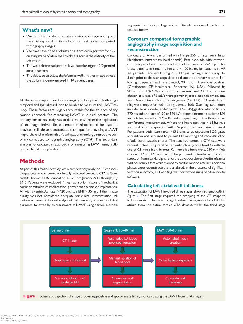
Calculating left atrial wall thicknessThe calculation of LAWT involved three stages, shown schematically inFigure 1. The first stage required the cropping of the CT image toisolate the atria. The second stage involved the segmentation of the leftatrium from the entire cardiac CTA dataset, whilst the third stage
CT Image
Crop region of interest
Manual calibration ofventricle HU
Set up:5 min
Automated LA bloodpool segmentation
Manual isolation ofblood pool
Automated wallsegmentation
Segment: 20–40 min
Automated meshcreation
Solve laplace equation
Calculate wallthickness
LAWT: 30–60 min
Figure 1 Schematic depiction of image processing pipeline and approximate timings for calculating the LAWT from CTA images.
What’s new?† We describe and demonstrate a protocol for segmenting out
the atrial myocardium tissue from contrast cardiac computedtomography images.
† We have developed a robust and automated algorithm for cal-culating maps of atrial wall thickness across the entirety of theleft atrium.
† The wall thickness algorithm is validated using on a 3D printedatrial phantom.
† The ability to calculate the left atrial wall thickness maps acrossthe atrium is demonstrated in 10 patient cases.
Left atrial wall thickness by cardiac computed tomography 377
Downloaded from https://academic.oup.com/europace/article-abstract/18/3/376/2398600by gueston 29 January 2018

involved solving the Laplace equations over a computational model gen-erated from the respective segmented left atrium.
SegmentationCreating a segmentation of the atria from any imaging modality is an es-sential part of calculating wall thickness. Images were segmented usingthe Python scripting tools for automating image processing stepswithin the freely available Seg3D2 software package.7 In brief, coronaryCTA scans were manually cropped to encapsulate the left atria. An auto-mated script applied a 4-point median filter to the image and segmentedthe left atrial blood cavity using a threshold value of 250 HU. The bloodpool threshold was manually corrected to remove spurious connectionswith the aorta, coronary sinus, and right atria. A sphere was place in theleft ventricle that identified the location of the mitral valve, and separatedany labelled ventricular blood from the left atrial blood pool. An auto-mated script then identified all viable atrial myocardial tissue. First,regions with 50–180 HU (this elevated value reflects the presence ofcontrast agent in the blood elevating the HU value of myocardium)were thresholded. These values were chosen based on the HU valuesof the left ventricular myocardium. Large thick contiguous regionswere removed from the mask of potential atrial tissue, due to the un-desired inclusion of the un-contrasted right atrial blood pool and basalleft ventricular tissue. The atrial blood pool, identified previously, wasthen removed from the reduced mask to identify all viable regions ofatrial tissue. The atrial wall was then segmented in layers. The first layerwas formed by dilating the blood pool region by 1 voxel as the atrialwall was assumed to be at least 1 voxel thick. The remaining layerswere determined by dilating the current atrial wall and adding anyregions that fell on voxels labelled previously as being viable atrialtissue. This was repeated four times. The final image was then dilatedand eroded by 2 voxels to remove any spurious segmentations.
Solving the Laplace equationsAt its simplest wall thickness can be calculated by the length of the normalprojection (Figure 2A) from either the endocardial (point x) or epicardial(point y) surface or the shortest Euclidian distance between the two sur-faces at any two points (Figure 2B).
However, as demonstrated in Figure 2, these approaches can generatespurious solutions, as indicated by the red arrows. From electromagnet-ism we know that by solving the Laplace equation we can derive a smoothset of non-intersecting field lines between two bodies, be they points,lines, sheets, or arbitrary objects. As shown in Figure 2C, a family ofdashed curves can be created that provide smooth, non-intersecting,and continuous lines between the surfaces. The distance of curves or-thogonal to these lines, then provides a measure of the wall thicknessat all points on the endocardial and epicardial surface. The length of thefield lines is calculated in three steps.
First the Laplace equation,
∇2u = 0 (1)is solved over the domain (V) encompassing the atrial wall, enclosed bythe endocardial (∂Vendo), epicardial (∂Vepi), and remaining (∂Vr) bound-ary surfaces. We impose boundary conditions
u|∂Vepi= 1
u|∂Vendo= 0
∂u∂n
∣∣∣∣∂Vr
= 0. (2)
In brief, Eq. (1) is solved using the finite element simulation platformCardiac Arrhythmia Research Package.8,9 High fidelity and resolutiontetrahedral meshes are created over the atrial wall using the Tarantulameshing software package (www.meshing.az) to mathematically definethe atrial wall domain (V). Unstructured tetrahedral meshes are usedto allow subvoxel resolution and remove potential bias in the solutionfrom regular voxel-based meshes. The nodes lying on the edge of thecropped segmentation image and within 1 mm of the sphere definingthe mitral valve are labelled as belonging to the remaining boundarysurface (∂Vr). A flood fill algorithm is then used to identify all unconnect-ed node groups that lie on the mesh surface. The first and second largestnode groups are then set as the epicardium and endocardium, respective-ly. All other surface nodes are labelled as lying on the remaining boundarysurface.
Calculating the length of field linesTo calculate the LAWT from the Laplace equations requires the calcula-tion of field lines and the subsequent integration of length along the fieldlines. The field line direction at each element in the finite element mesh iscalculated from
v = ∇u||∇u|| . (3)
Tocalculate the length of field line particles is seeded on theendocardiumand epicardium. The particles move away from their initial surface in thedirection of the vector field (Eq. 3). Tracking the distance travelled by aparticle as it traverses from the endocardium to epicardium or viceversa then gives the wall thickness at the point of the particle’s origin.
Left atrium phantomA left atrium phantom was created to validate the Laplace wall thicknessmethod applied to CT images. The phantom was designed to test the ac-curacy of the wall thickness measurements and determine the limits ofthe method within the resolution constraints of CT. The model wascreated in Solidworks and printed using a 100 mm resolution resin 3Dprinter. The model was scanned using the cardiac CT protocol with anECG emulator.
Endocardium
Epicardium
y y y
x xx
A B C
Figure 2 Schematic showing different approaches for measuringatrial wall thickness between the endocardium (turquoise surface)and epicardium (green surface). (A) Left atrial wall thickness calcu-lated using a normal projection from the surface generates a spuri-ous result at point × (red arrow). (B) Left atrial wall thicknesscalculated using a nearest point on the opposing surface generatesa spurious result for point y. (C) The Laplace method calculatessmooth dashed lines between the endocardium and epicardium.Paths that are orthogonal to these lines (black arrows) are usedto calculate the wall thickness removing the spurious resultsobserved in the normal projection and nearest point approaches.
M. Bishop et al.378
Downloaded from https://academic.oup.com/europace/article-abstract/18/3/376/2398600by gueston 29 January 2018
Computation and visualizationAll results were performed using a 12 core Xeon X5650 2.67 GHz LinuxDell work station with 40 Gb of memory. Meshes and all results werevisualized using Meshalyzer courtesy of Dr E. J. Vigmond.
Results
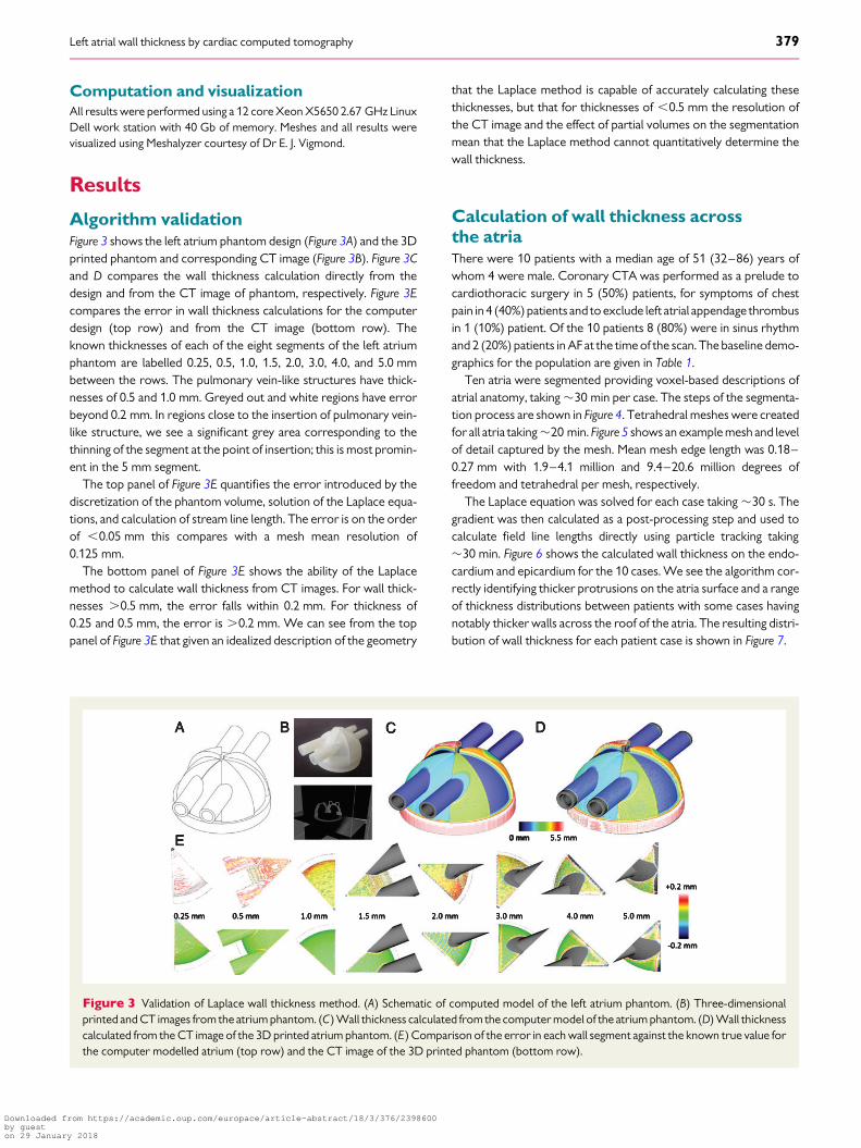
Algorithm validationFigure 3 shows the left atrium phantom design (Figure 3A) and the 3Dprinted phantom and corresponding CT image (Figure 3B). Figure 3Cand D compares the wall thickness calculation directly from thedesign and from the CT image of phantom, respectively. Figure 3Ecompares the error in wall thickness calculations for the computerdesign (top row) and from the CT image (bottom row). Theknown thicknesses of each of the eight segments of the left atriumphantom are labelled 0.25, 0.5, 1.0, 1.5, 2.0, 3.0, 4.0, and 5.0 mmbetween the rows. The pulmonary vein-like structures have thick-nesses of 0.5 and 1.0 mm. Greyed out and white regions have errorbeyond 0.2 mm. In regions close to the insertion of pulmonary vein-like structure, we see a significant grey area corresponding to thethinning of the segment at the point of insertion; this is most promin-ent in the 5 mm segment.
The top panel of Figure 3E quantifies the error introduced by thediscretization of the phantom volume, solution of the Laplace equa-tions, and calculation of stream line length. The error is on the orderof ,0.05 mm this compares with a mesh mean resolution of0.125 mm.
The bottom panel of Figure 3E shows the ability of the Laplacemethod to calculate wall thickness from CT images. For wall thick-nesses .0.5 mm, the error falls within 0.2 mm. For thickness of0.25 and 0.5 mm, the error is .0.2 mm. We can see from the toppanel of Figure 3E that given an idealized description of the geometry
that the Laplace method is capable of accurately calculating thesethicknesses, but that for thicknesses of ,0.5 mm the resolution ofthe CT image and the effect of partial volumes on the segmentationmean that the Laplace method cannot quantitatively determine thewall thickness.
Calculation of wall thickness acrossthe atriaThere were 10 patients with a median age of 51 (32–86) years ofwhom 4 were male. Coronary CTA was performed as a prelude tocardiothoracic surgery in 5 (50%) patients, for symptoms of chestpain in 4 (40%) patients and to exclude left atrial appendage thrombusin 1 (10%) patient. Of the 10 patients 8 (80%) were in sinus rhythmand 2 (20%) patients in AF at the time of the scan. The baseline demo-graphics for the population are given in Table 1.
Ten atria were segmented providing voxel-based descriptions ofatrial anatomy, taking �30 min per case. The steps of the segmenta-tion process are shown in Figure 4. Tetrahedral meshes were createdfor all atria taking �20 min. Figure 5 shows an example mesh and levelof detail captured by the mesh. Mean mesh edge length was 0.18–0.27 mm with 1.9–4.1 million and 9.4–20.6 million degrees offreedom and tetrahedral per mesh, respectively.
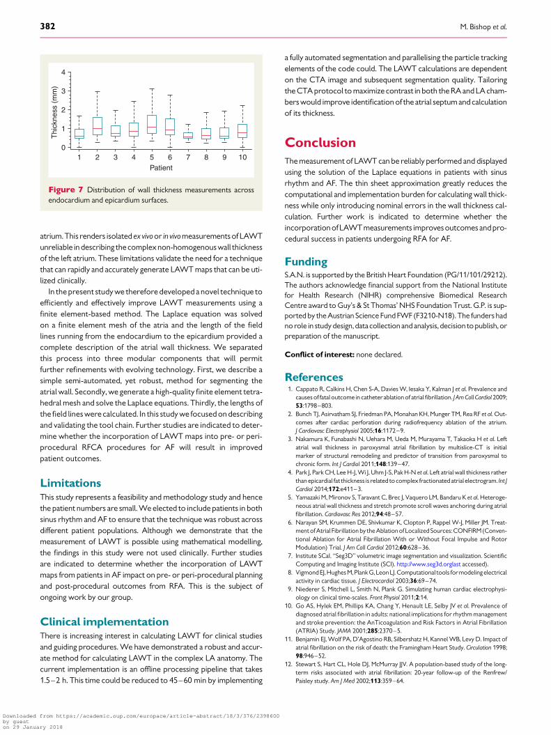
The Laplace equation was solved for each case taking �30 s. Thegradient was then calculated as a post-processing step and used tocalculate field line lengths directly using particle tracking taking�30 min. Figure 6 shows the calculated wall thickness on the endo-cardium and epicardium for the 10 cases. We see the algorithm cor-rectly identifying thicker protrusions on the atria surface and a rangeof thickness distributions between patients with some cases havingnotably thicker walls across the roof of the atria. The resulting distri-bution of wall thickness for each patient case is shown in Figure 7.
0 mm
Figure 3 Validation of Laplace wall thickness method. (A) Schematic of computed model of the left atrium phantom. (B) Three-dimensionalprinted and CT images from the atrium phantom. (C) Wall thickness calculated from the computer model of the atrium phantom. (D) Wall thicknesscalculated from the CT image of the 3D printed atrium phantom. (E) Comparison of the error in each wall segment against the known true value forthe computer modelled atrium (top row) and the CT image of the 3D printed phantom (bottom row).
Left atrial wall thickness by cardiac computed tomography 379
Downloaded from https://academic.oup.com/europace/article-abstract/18/3/376/2398600by gueston 29 January 2018

DiscussionIn the present study we validate and apply for the first time a noveltool chain to robustly calculate LAWT across the entire left atrium.
Atrial fibrillation is the most common sustained arrhythmiawith anestimated overall prevalence of 0.95%.10 It is associated with signifi-cant morbidity and mortality from stroke, sudden cardiac death,heart failure, and impaired cognitive function.11,12 Although pulmon-ary vein isolation by RFA has emerged as an effective treatment forcarefully selected symptomatic patients, the long-term successrates remain suboptimal with repeated procedures often beingrequired. It is possible that the incorporation of LAWT measure-ments into pre-procedural planning and intra-procedural guidancemay be useful in improving patient outcomes by identifying thin high-risk locations, identifying ablation targets and permitting titration ofRF energy and contact force according to site- and patient-specificstructural characteristics.
Despite these potential benefits, the measurement of LAWT ischallenging. There is a high degree of left atrial anatomical variabilitywith individual patients having atria with a distinct size, shape, andnumber of pulmonary veins.13 In addition, the walls of the atriaconsist of multiple tissue types, with distinct physiology, roles, andproperties. The left atrial wall predominantly consists of atrial myo-cytes but also contains fibrous and fatty tissue that make up an im-portant component of the total wall thickness.14 The significantvariation in wall thickness across the atria, the lack of a unique repeat-able anatomic reference system, and ambiguity in the definition ofwall thickness leads to significant variation in reported wall thicknessmeasurements for different methodologies and patient popula-tions.15 –20 Previous direct measurements of atrial wall thicknesshave been performed ex vivo in cadaveric anatomical studies.15,16
These measurements were performed at discrete locations andmay have included varying amounts of fatty or fibrous tissue in thethickness measurements. The results from these two studies are dis-crepant: atrial thickness wasmeasured at2.1–2.9 mm across the roofof the atria in one study15 but was more than 50% thinner with a meanroof thickness of 1.06 mm in a second study.16 Variation in thicknessbetweenatrial regions has also been observed in CT studies of the leftatrium,15 which reveal consistently smaller wall thicknesses whencompared with cadaveric studies. This may reflect the limited reso-lution of CT measurements due to voxel size in earlier studies, thatCT differentiates myocardium from fat and hence different tissuefractions are included in the measurement17 or, that the fixationprocess affects measurements. In studies that have measured
Table 1 Baseline demographics
Age (years) 51 (32–86)
Gender (M:F) 4:6
Smoking history, n (%) 3 (30%)
Cardiovascular risk factors
Hypercholesterolemia, n (%) 2 (20%)
Hypertension, n (%) 4 (40%)
Positive family history, n (%) 2 (20%)
Diabetes mellitus, n (%) 0 (0%)
Atrial fibrillation, n (%) 2 (20%)
Coronary CTA indication
Chest pain, n (%) 4 (40%)
Prelude to cardiothoracic surgery, n (%) 5 (50%)
Left atrial appendage thrombus, n (%) 1 (%)
Coronary CTA scan mode
Prospective, n (%) 8 (80%)
Retrospective, n (%) 2 (20%)
Mean heart rate (b.p.m.) 61 (+12)
Total dose length product (mGy cm) 415 (+338)
Peak tube voltage (kVp) 116 (+8)
Tube current (mA) 511 (+141)
Figure 4 Segmentation of the atrium. (A) Raw CT image. (B) Finalsegmentation. (C) Cropped image. (D) Application of median filter.(E) Thresholded blood pool. (F) Manually corrected blood pool.(G) Thresholded viable atrial tissue. (H ) Right atrium and left ven-tricle regions. (I ) removal of right atrium and left ventricle regionsfrom viable atrial tissue. (J ) Removal of blood pool from viableatrial tissue. (K ) Dilation of blood pool. (L) Removal of bloodpool to identify single voxel shell. (M) Dilation of atrial wall thatoverlaps with viable atrial tissue. (N ) Smoothed atrial wall.
M. Bishop et al.380
Downloaded from https://academic.oup.com/europace/article-abstract/18/3/376/2398600by gueston 29 January 2018

LAWT along lines of ablation in patients with AF, there has been con-siderable variability with measurements varying from 2.1–2.9 mm18
to 0–7.7 mm.19 This significant variation both between patients andacross different regions of the atria motivates the need to measureregional wall thickness in individuals.
There are a number of limitations to previously reported techni-ques for measuring LAWT. In ex vivo fixed preparations of the leftatrium, the measurements of LAWT using calipers likely included fi-brotic, fat, and myocardial tissue. In addition, it is recognised thatthere is variability in LAWT measurements at different sites of the
Figure 5 Atria (A) segmentation and corresponding (B) mesh. Increasing zoom of mesh resolution is shown in (C)–(E).
Figure 6 Endocardial and epicardial wall thickness from 0 mm (dark blue) to 5 mm (red) for patients 1–10 (A– J), respectively.
Left atrial wall thickness by cardiac computed tomography 381
Downloaded from https://academic.oup.com/europace/article-abstract/18/3/376/2398600by gueston 29 January 2018
atrium.This renders isolated ex vivoor in vivomeasurements of LAWTunreliable in describing the complexnon-homogenouswall thicknessof the left atrium. These limitations validate the need for a techniquethat can rapidly and accurately generate LAWT maps that can be uti-lized clinically.
In the present study we therefore developed a novel technique toefficiently and effectively improve LAWT measurements using afinite element-based method. The Laplace equation was solvedon a finite element mesh of the atria and the length of the fieldlines running from the endocardium to the epicardium provided acomplete description of the atrial wall thickness. We separatedthis process into three modular components that will permitfurther refinements with evolving technology. First, we describe asimple semi-automated, yet robust, method for segmenting theatrial wall. Secondly, we generate a high-quality finite element tetra-hedral mesh and solve the Laplace equations. Thirdly, the lengths ofthe field lines were calculated. In this study we focused on describingand validating the tool chain. Further studies are indicated to deter-mine whether the incorporation of LAWT maps into pre- or peri-procedural RFCA procedures for AF will result in improvedpatient outcomes.
LimitationsThis study represents a feasibility and methodology study and hencethe patient numbers are small. We elected to include patients in bothsinus rhythm and AF to ensure that the technique was robust acrossdifferent patient populations. Although we demonstrate that themeasurement of LAWT is possible using mathematical modelling,the findings in this study were not used clinically. Further studiesare indicated to determine whether the incorporation of LAWTmaps from patients in AF impact on pre- or peri-procedural planningand post-procedural outcomes from RFA. This is the subject ofongoing work by our group.
Clinical implementationThere is increasing interest in calculating LAWT for clinical studiesand guiding procedures. We have demonstrated a robust and accur-ate method for calculating LAWT in the complex LA anatomy. Thecurrent implementation is an offline processing pipeline that takes1.5–2 h. This time could be reduced to 45–60 min by implementing
a fully automated segmentation and parallelising the particle trackingelements of the code could. The LAWT calculations are dependenton the CTA image and subsequent segmentation quality. Tailoringthe CTA protocol to maximize contrast in both the RA and LA cham-bers would improve identification of the atrial septum and calculationof its thickness.
ConclusionThe measurement of LAWT can be reliably performed and displayedusing the solution of the Laplace equations in patients with sinusrhythm and AF. The thin sheet approximation greatly reduces thecomputational and implementation burden for calculating wall thick-ness while only introducing nominal errors in the wall thickness cal-culation. Further work is indicated to determine whether theincorporationof LAWT measurements improvesoutcomes andpro-cedural success in patients undergoing RFA for AF.
FundingS.A.N. is supported by the British Heart Foundation (PG/11/101/29212).The authors acknowledge financial support from the National Institutefor Health Research (NIHR) comprehensive Biomedical ResearchCentre award to Guy’s & St Thomas’ NHS Foundation Trust. G.P. is sup-ported by the Austrian Science Fund FWF (F3210-N18). The funders hadno role in study design, data collection and analysis, decision to publish, orpreparation of the manuscript.
Conflict of interest: none declared.
References1. Cappato R, Calkins H, Chen S-A, Davies W, Iesaka Y, Kalman J et al. Prevalence and
causes of fatal outcome in catheter ablation of atrial fibrillation. J Am Coll Cardiol 2009;53:1798–803.
2. Bunch TJ, Asirvatham SJ, Friedman PA, Monahan KH, Munger TM, Rea RF et al. Out-comes after cardiac perforation during radiofrequency ablation of the atrium.J Cardiovasc Electrophysiol 2005;16:1172–9.
3. Nakamura K, Funabashi N, Uehara M, Ueda M, Murayama T, Takaoka H et al. Leftatrial wall thickness in paroxysmal atrial fibrillation by multislice-CT is initialmarker of structural remodeling and predictor of transition from paroxysmal tochronic form. Int J Cardiol 2011;148:139–47.
4. Park J, Park CH, Lee H-J, Wi J, Uhm J-S, Pak H-N et al. Left atrial wall thickness ratherthan epicardial fat thickness is related to complex fractionated atrial electrogram. Int JCardiol 2014;172:e411–3.
5. Yamazaki M, Mironov S, Taravant C, Brec J, Vaquero LM, Bandaru K et al. Heteroge-neous atrial wall thickness and stretch promote scroll waves anchoring during atrialfibrillation. Cardiovasc Res 2012;94:48–57.
6. Narayan SM, Krummen DE, Shivkumar K, Clopton P, Rappel W-J, Miller JM. Treat-ment of Atrial Fibrillation by the Ablation of Localized Sources: CONFIRM(Conven-tional Ablation for Atrial Fibrillation With or Without Focal Impulse and RotorModulation) Trial. J Am Coll Cardiol 2012;60:628–36.
7. Institute SCaI. “Seg3D” volumetric image segmentation and visualization. ScientificComputing and Imaging Institute (SCI). http://www.seg3d.orglast accessed).
8. Vigmond EJ,HughesM, Plank G, LeonLJ. Computational tools formodeling electricalactivity in cardiac tissue. J Electrocardiol 2003;36:69–74.
9. Niederer S, Mitchell L, Smith N, Plank G. Simulating human cardiac electrophysi-ology on clinical time-scales. Front Physiol 2011;2:14.
10. Go AS, Hylek EM, Phillips KA, Chang Y, Henault LE, Selby JV et al. Prevalence ofdiagnosed atrial fibrillation in adults: national implications for rhythm managementand stroke prevention: the AnTicoagulation and Risk Factors in Atrial Fibrillation(ATRIA) Study. JAMA 2001;285:2370–5.
11. Benjamin EJ, Wolf PA, D’Agostino RB, Silbershatz H, Kannel WB, Levy D. Impact ofatrial fibrillation on the risk of death: the Framingham Heart Study. Circulation 1998;98:946–52.
12. Stewart S, Hart CL, Hole DJ, McMurray JJV. A population-based study of the long-term risks associated with atrial fibrillation: 20-year follow-up of the Renfrew/Paisley study. Am J Med 2002;113:359–64.
01
1
2
Thi
ckne
ss (
mm
)
3
4
2 3 4 5Patient
6 7 8 9 10
Figure 7 Distribution of wall thickness measurements acrossendocardium and epicardium surfaces.
M. Bishop et al.382
Downloaded from https://academic.oup.com/europace/article-abstract/18/3/376/2398600by gueston 29 January 2018
13. Ho SY, Sanchez-Quintana D. The importance of atrial structure and fibers. Clin Anat2009;22:52–63.
14. Sanchez-Quintana D, Cabrera JA, Climent V, Farre J, de Mendonca MC, Ho SY. Ana-tomic relations between the esophagus and left atrium and relevance for ablation ofatrial fibrillation. Circulation 2005;112:1400–5.
15. Platonov PG, Ivanov V, Ho SY, Mitrofanova L. Left atrial posterior wall thickness inpatients with and without atrial fibrillation: data from 298 consecutive autopsies.J Cardiovasc Electrophysiol 2008;19:689–92.
16. Hall B, Jeevanantham V, Simon R, Filippone J, Vorobiof G, Daubert J. Variation in leftatrial transmural wall thickness at sites commonly targeted for ablation of atrial fib-rillation. J Interv Card Electrophysiol 2006;17:127–32.
17. Beinart ROY, Abbara S, Blum A, Ferencik M, Heist K, Ruskin J et al. Left atrial wallthickness variability measured by CT scans in patients undergoing pulmonary veinisolation. J Cardiovasc Electrophysiol 2011;22:1232–6.
18. Cho Y, Lee W, Park E-A, Oh I-Y, Choi E-K, Seo J-W et al. The anatomical character-istics of three different endocardial lines in the left atrium: evaluation by computedtomography prior to mitral isthmus block attempt. Europace 2012;14:1104–11.
19. Becker AE. Left atrial isthmus. J Cardiovasc Electrophysiol 2004;15:809–12.20. Park YM, Park HC, Ban JE, Choi JI, Lim HE, Park SW et al. Interatrial septal thickness is
associated with the extent of left atrial complex fractionated atrial electrograms andacute procedural outcome in patients with persistent atrial fibrillation. Europace2015;17:1700–7.
EP CASE EXPRESS. . . . . . . . . . . . . . . . . . . . . . . . . . . . . . . . . . . . . . . . . . . . . . . . . . . . . . . . . . . . . . . . . . . . . . . . . . . . . . . . . . . . . . . . . . . . . . . . . . . . . . . . . . . . . . . . . . . . . . . . . . . . . . . . . . . . . . . . . . . . . . . . . . . . . . . . . . . . . . . . . . . . . . . . . . . . .
doi:10.1093/europace/euv407Online publish-ahead-of-print 30 December 2015
Mitral isthmus ablation: the importance of epicardial connections betweenthe coronary sinus and Marshall bundleTakekuni Hayashi*, Takeshi Mitsuhashi, and Shin-ichi Momomura
Division of Cardiovascular Medicine, Saitama Medical Center, Jichi Medical University, 1-847, Amanuma, Oomiya-ku, Saitama 330-8503, Japan
*Corresponding author. Tel: +81 48 647 2111; fax: +81 48 647 5188. E-mail address: [email protected]
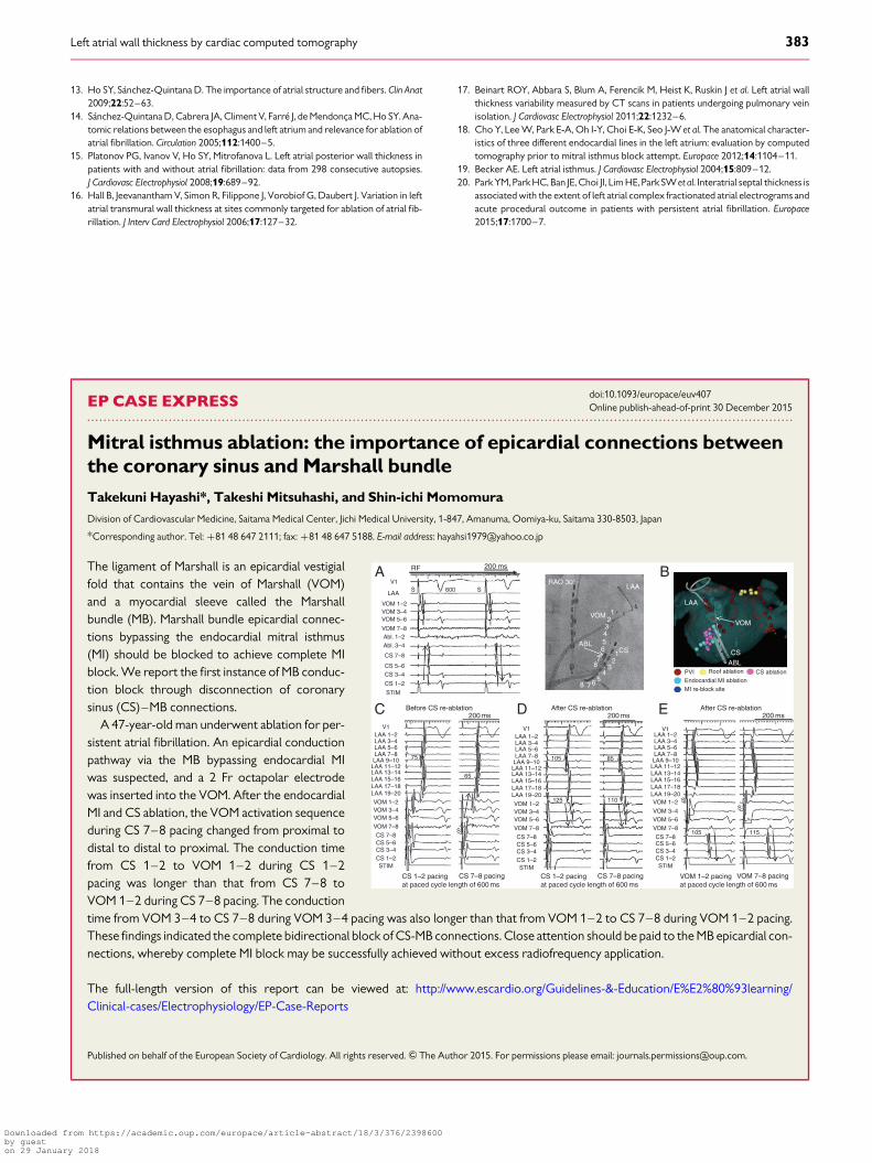
The ligament of Marshall is an epicardial vestigialfold that contains the vein of Marshall (VOM)and a myocardial sleeve called the Marshallbundle (MB). Marshall bundle epicardial connec-tions bypassing the endocardial mitral isthmus(MI) should be blocked to achieve complete MIblock. We report the first instance of MB conduc-tion block through disconnection of coronarysinus (CS)–MB connections.
A 47-year-old man underwent ablation for per-sistent atrial fibrillation. An epicardial conductionpathway via the MB bypassing endocardial MIwas suspected, and a 2 Fr octapolar electrodewas inserted into the VOM. After the endocardialMI and CS ablation, the VOM activation sequenceduring CS 7–8 pacing changed from proximal todistal to distal to proximal. The conduction timefrom CS 1–2 to VOM 1–2 during CS 1–2pacing was longer than that from CS 7–8 toVOM 1–2 during CS 7–8 pacing. The conductiontime from VOM 3–4 to CS 7–8 during VOM 3–4 pacing was also longer than that from VOM 1–2 to CS 7–8 during VOM 1–2 pacing.These findings indicated the complete bidirectional block of CS-MB connections. Close attention should be paid to the MB epicardial con-nections, whereby complete MI block may be successfully achieved without excess radiofrequency application.
The full-length version of this report can be viewed at: http://www.escardio.org/Guidelines-&-Education/E%E2%80%93learning/Clinical-cases/Electrophysiology/EP-Case-Reports
Published on behalf of the European Society of Cardiology. All rights reserved. & The Author 2015. For permissions please email: [email protected].
RF
V1A
C D E
BLAA
LAA 1–2LAA 3–4LAA 5–6
75
65
125
105 85
110
S
CS 1–2 pacingat paced cycle length of 600 ms
LAA 7–8LAA 9–10LAA 11–12LAA 13–14LAA 15–16LAA 17–18LAA 19–20
VOM 1–2VOM 3–4VOM 5–6
VOM 7–8
CS 7–8CS 5–6CS 3–4CS 1–2STIM
V1
LAA 1–2LAA 3–4LAA 5–6LAA 7–8LAA 9–10
LAA 11–12LAA 13–14LAA 15–16LAA 17–18LAA 19–20
VOM 1–2VOM 3–4VOM 5–6
VOM 7–8
CS 7–8CS 5–6CS 3–4CS 1–2STIM
V1LAA 1–2LAA 3–4LAA 5–6LAA 7–8LAA 9–10
LAA 11–12LAA 13–14LAA 15–16LAA 17–18LAA 19–20VOM 1–2 S
S
105 115
VOM 3–4VOM 5–6
VOM 7–8
CS 7–8CS 5–6CS 3–4CS 1–2STIM
V1
VOM 1–2VOM 3–4VOM 5–6
VOM 7–8Abl. 1–2Abl. 3–4
CS 7–8
CS 5–6CS 3–4
CS 1–2
STIM
Before CS re-ablation After CS re-ablation After CS re-ablation200 ms 200 ms 200 ms
S 600 SRAO 30°
VOMVOM
ABLPVI Roof ablation CS ablationEndocardial MI ablationMI re-block site
1
1
2
2
3
3
4
4
5
5
6
6
7
7
8
8
CS CSABL
LAA
LAA
200 ms
CS 7–8 pacing CS 1–2 pacingat paced cycle length of 600 ms
CS 7–8 pacing VOM 1–2 pacingat paced cycle length of 600 ms
VOM 7–8 pacing
Left atrial wall thickness by cardiac computed tomography 383
Downloaded from https://academic.oup.com/europace/article-abstract/18/3/376/2398600by gueston 29 January 2018