Embed Size (px)
Citation preview

1
17 Three Bond Technical News Issued March 20, 1987
Ultraviolet-Ozone Surface Treatment
1. Summary
The production process for all components includes one or more cleanings, and the quality of the cleaning significantly influences the improvements in the yield.
With the recent development of micromachining technology in electronics, conventional cleaning methods are increasingly inadequate in many fields; thus, several new cleaning methods have been developed.
However, newly developed cleaning apparatuses each have advantages and disadvantages, and at present cannot be regarded as prevalent. The ultraviolet-ozone
cleaning (hereinafter referred to as "UV-O3 cleaning") apparatus described herein seems not to affect the object to be cleaned, and seems to enable easy precision cleaning in a relatively wide range.
Currently, the various cleaning techniques are used, and their methods can be broadly classified into two types: wet cleaning and dry cleaning. The UV-O3 cleaning method has the characteristics of dry cleaning.
Table 1 shows examples of the dry-cleaning methods.
Contents 1. Summary ......................................................................................................... 1 2. UV-O3 cleaning technology.............................................................................. 2
2-1. Principle of UV-O3 cleaning...................................................................... 2 2-2. Evaluation of cleanliness.......................................................................... 3 2-3. Application of UV-O3 cleaning .................................................................. 3 2-4. Contaminants removable by UV-O3 cleaning........................................... 4
3. UV-O3 cleaning experimental apparatus ......................................................... 4 4. Importance of preliminary cleaning ................................................................. 6 5. Ultraviolet-ozone cleaning lamp ...................................................................... 6 6. Structure of ultraviolet-ozone cleaning apparatus ........................................... 7 7. Results of the UV-O3 cleaning experiments .................................................... 8

2
Dry cleaning 1) Laser and X-ray cleaning Cleaning by thermal action
2) Plasma cleaning Cleaning by the collision energy of gas molecules and the chemical action on contaminants
3) Cleaning by ion milling Cleaning by surface etching
4) UV-O3 cleaning Cleaning by the decomposition of contaminants by ultraviolet irradiation and the chemical action of oxidation by O3
Table 1. Examples of dry cleaning method
In general, contaminants are classified into the organic and inorganic types. Organic contaminants include machine oils, vacuum-pump oils, and human sebum, and inorganic ones include dusts, metal powder, tobacco smoke, and salts.
Table 2 shows examples of organic contaminants.
1) Cutting oils 2) Mixtures of beeswax and pine resin 3) Lapping agents 4) Vacuum-pump oils, silicon diffusion-pump oils 5) Silicon vacuum greases 6) Soldering fluxes 7) Human sebum 8) Contaminants attached during long-term air exposure 9) Carbon thin films formed by vacuum deposition
Table 2. Examples of organic contaminants1) UV-O3 cleaning is generally effective for
removing organic contaminants, though it may be ineffective for removing inorganic contaminants. Therefore, as preliminary cleaning, inorganic contaminants must be removed in advance using pure water, solvents, or the like before UV-O3 cleaning is conducted.
2. UV-O3 cleaning technique The decomposition of carbohydrates by
ultraviolet irradiation has been known, but surface cleaning by ultraviolet irradiation and its applicability to the manufacture of electronic components have not been studied until recently.
In 1972, Bolon and Kuns succeeded in decomposing photoresist polymers by ultraviolet irradiation.1) This enabled the achievement of very clean surfaces. J.R. VIG used UV-O3 cleaning to clean the surface of crystal oscillators.1) Even monolayer contamination will significantly affect the frequency change of the oscillators.
2-1. Principle of UV-O3 cleaning The principle of UV-O3 cleaning is as follows:
organic compounds are converted into volatile
substances (e.g., water, carbon dioxide, nitrogen) by decomposition by ultraviolet rays and by strong oxidation during the formation and decomposition of O3, and are removed from the contaminated surface.
The major wavelengths of the ultraviolet rays radiated from a well-known low-pressure mercury vapor lamp are 184.9 nm and 253.7 nm. When atmospheric oxygen O2 is irradiated with ultraviolet rays with a wavelength of 184.9 nm, the oxygen absorbs the ultraviolet rays to form O3 by the following reaction:
Ultraviolet rays with a wavelength of 189.4 nm
Ozone O3 irradiated with ultraviolet rays with a wavelength of 253.7 nm absorbs the ultraviolet light to decompose O3. During the process of formation or decomposition of O3, atomic oxygen O having a strong oxidizing ability is generated.
Then, contaminant organic compounds are irradiated with ultraviolet rays, and absorb the ultraviolet rays to cause photolysis and generate the following substances:
O2 O + O O + O2 O3
3
The energy E per mol of an electromagnetic wave has a relationship with the wavelength λ as expressed by the following formula:
E=Nhc/λ × 105 KJ・mol-1 Where
h is Planck's constant (6.626 × 10⁻³⁴ J•Sec), c is the velocity of light (2.998 × 1010 cm•Sec-1), λ is the wavelength (cm), and N is Avogadro's constant (6.022 × 10²³ mol-1).
The energy E per mol of ultraviolet rays with a wavelength of 184.9 nm is
184910998.210626.610022.6 103423
)1849(×××××
=−
E
× 105 KJ・mol-1 = 647 KJ•mol-1 In a like manner, the energy E(2537) per mol of
ultraviolet rays with a wavelength of 253.7 nm is: E(2537) = 472 KJ•mol-1
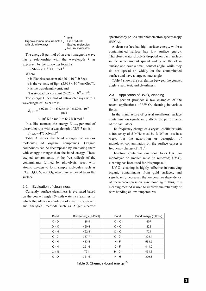
Table 3 shows the bond energies of various molecules of organic compounds. Organic compounds can be decomposed by irradiating them with energy stronger than the bond energy. These excited contaminants, or the free radicals of the contaminants formed by photolysis, react with atomic oxygen to form simple molecules such as CO2, H2O, N, and O2, which are removed from the surface.
2-2. Evaluation of cleanliness Currently, surface cleanliness is evaluated based
on the contact angle (θ) with water, a steam test in which the adhesion condition of steam is observed, and analytical methods such as Auger electron
spectroscopy (AES) and photoelectron spectroscopy (ESCA).
A clean surface has high surface energy, while a contaminated surface has low surface energy. Therefore, water droplets dropped on each surface in the same amount spread widely on the clean surface and have a small contact angle, while they do not spread so widely on the contaminated surface and have a large contact angle.
Table 4 shows the correlation between the contact angle, steam test, and cleanliness.
2-3. Application of UV-O3 cleaning This section provides a few examples of the
recent applications of UV-O3 cleaning in various fields.
In the manufacture of crystal oscillators, surface contamination significantly affects the performance of the oscillators.
The frequency change of a crystal oscillator with a frequency of 5 MHz must be 2/1010 or less in a week, but the adsorption or desorption of monolayer contamination on the surface causes a frequency change of 1/106.
Therefore, contaminations equal to or less than monolayer or smaller must be removed; UV-O3 cleaning has been used for this purpose.1)
UV-O3 cleaning is highly effective in removing organic contaminants from gold surfaces, and significantly decreases the temperature dependency of thermo-compression wire bonding.1) Thus, this cleaning method is used to improve the reliability of wire bonding at low temperatures.
Bond Bond energy (KJ/mol) Bond Bond energy (KJ/mol)
O - O 138.9 C = C 607
O = O 490.4 C ≡ C 828
O - H 462.8 C = O 724
C - C 347.7 C - Cl 328.4
C - H 413.4 H - F 563.2
C - N 291.6 C - F 441.0
C ≡ N 791 H - Cl 431.8
C - O 351.5 N - H 309.8
Table 3. Chemical-bond energy 2)
Organic compounds irradiated with ultraviolet rays
Ions Free radicals Excited molecules Neutral molecules

4
Results of the steam test Conditions of steam condensation on polished quartz Contact angle Contaminant monolayer
Excellent interference fringes Uniform rainbow fringes during both condensation and evaporation 4° < 0.1
Good interference fringes Uniform ray fringes during condensation, irregular fringes during evaporation 4° < 0.1
Bad interference fringes Irregular fringes during condensation 4° ≤ 0.1 Orange peel Colorless, water droplets, transparent 5° to 10° 0.1 to 1 Mist Translucent due to many small water droplets > 10° 1
Table 4. Correlation between the contact angle, steam test, and cleanliness1) This cleaning method has also been used for
removing the following materials in pretreatment for coating of a photoresist, and for improving the adhesive force of adhesives. 1) Glass plates 2) Chrome masks 3) Nesa films 4) Semiconductors (e.g., silicon wafers) 5) Metals (e.g., copper, aluminum, SUS, nickel) 6) Ceramic plates
The following uses are suggested for the application of UV-O3 cleaning: 1) Surface treatment prior to coating, plating, or
vaporization 2) Clean oxidation of metal and semiconductor
surfaces 3) Modification of polymer surfaces 4) Peeling and etching of photoresist thin films 5) Others
2-4. Contaminants removable by UV-O3 cleaning
1. Cutting oils 2. Mixtures of beeswax and pine resin 3. Lapping agents 4. Vacuum-pump oils 5. Silicon diffusion-pump oils 6. Silicon vacuum greases 7. Soldering fluxes 8. Human sebum 9. Contaminants adsorbed during long-term air
exposure 10. Carbon thin films formed by vacuum
evaporation
3. UV-O3-cleaning experimental apparatus
As an experimental apparatus for UV-O3 cleaning,
a stainless-steel apparatus as shown in Fig. 1 (a) and (b) was manufactured.
In Fig. 2 (a), a sample was irradiated with ultraviolet rays with wavelengths of 184.9 nm and 253.7 nm, and then O3 was formed in the apparatus. In (b), an ozoneless quartz plate was placed between the sample and the light source, the sample was irradiated with ultraviolet rays with a wavelength of 253.7 nm only, and no O3 was formed in the apparatus.
In apparatus (a), contaminants were exposed to O3 and ultraviolet rays with wavelengths of 184.9 nm and 253.7 nm, while in apparatus (b) they were exposed to ultraviolet rays with a wavelength of 253.7 nm only. The irradiation distance assumed to be approximately 5 mm.
The results of the two experiments are described below.
In apparatus (a), the contact angle with water droplets of the sample exposed to 184.9 nm + 253.7 nm + O3 decreased from 35° before treatment to 4° less within 20 seconds to 60 seconds.
In apparatus (b), the sample exposed to 253.7 nm could not achieve a contact angle of 4° or less even after one to several hours.
These experiments showed that the irradiation of ultraviolet rays only cannot achieve an immediate and sufficient and cleaning effect.
Fig. 2 shows the results of the ESCA analysis of the surface of the quartz glass plate that had achieved a contact angle of 4° or less. Few carbon peaks were detected on the cleaned surface, indicating the effect of UV-O3 cleaning.
Additionally, in the results of the AES analysis of the gold surfaces before and after UV-O3 cleaning (Fig. 3), few carbon peaks were detected on the cleaned surface.

5
Fig. 1
(a) Composition of the contaminated surface O-14%, Si-8%, C-78% (b) Composition of the cleaned surface O-65%, Si-33%, C-2%
Fig. 2. ESCA analysis results of the quartz surface before and after ultraviolet irradiation3)
Aluminum reflector plate
Num
ber o
f vol
tage
s N
(E
) Ozoneless quartz plate 253.7-nm ultraviolet rays
No O3
Low-pressure mercury lamp
184.9-nm 253.7-nm
ultraviolet rays
O3
Cleaned sample
Sample table
O3 184.9-nm 253.7-nm
ultraviolet rays
(a) Contaminated surface
(b) Ultraviolet-irradiated cleaned surface
Num
ber o
f vol
tage
s N
(E)
Bond energy of electrons (eV)

6
Fig. 3. AES analysis results of the gold surface before and after ultraviolet-rays/ozone cleaning4)
4. Importance of preliminary
cleaning UV-O3 cleaning is effective in removing organic
compounds, but is not effective in removing dust and inorganic salts. In addition, if contaminants of organic compounds form a thick film, many polymers in the surface area may be decomposed by ultraviolet irradiation. However, the polymers on the inside containing no oxygen crosslink with each other and do not cause photolysis.
For this reason, effective UV-O3 cleaning requires preliminary cleaning of the surface. The preliminary cleaning is conducted primarily to remove contaminants such as dust and salts that cannot be converted into volatile products by the oxidation action of UV-O3 cleaning, and secondarily to remove a thick coating of the contaminants, the majority of which is likely to be converted into a UV-resistant coating by the crosslinking action of ultraviolet rays immersing from the surface.
5. Ultraviolet-ozone cleaning lamp
Practically usable ultraviolet-ozone cleaning lamps must effectively radiate lights with wavelengths of 184.9 nm and 253.7 nm. Ultraviolet
rays with a wavelength of 184.9 nm are absorbed by oxygen to form ozone. On the other hand, ultraviolet rays with a wavelength of 253.7 nm are absorbed by ozone to decompose the ozone, or is absorbed by most hydrocarbon substances to decompose them.
Thus, the coexistence of wavelengths of 184.9 nm and 253.7 nm causes the continuous formation and/or decomposition of ozone. In particular, atomic oxygen formed during the formation and decomposition of ozone acts as a strong oxidizer.
Light sources include low-pressure mercury lamps, medium-pressure mercury lamps, and high-pressure mercury lamps. The light of a low-pressure mercury lamp consists of 90% of 253.7 nm and several % of 184.9 Å. Fig. 4 shows the radiation spectral distribution of a low-pressure mercury lamp, and Fig. 5 shows the absorption properties of ozone. When ozone exists between a light source and a sample, the absorption changes the illuminance on the sample according to the distance and concentration of the ozone. Ozone has a broad absorption band in the vicinity of 260 nm, and an absorption coefficient of 120 cm-1atm-1 for 253.7 nm. Fig. 6 shows the absorption coefficient according to the wavelength of ozone.
Electron energy (a) Before cleaning
Electron energy (b) After cleaning

7
Fig. 4
Fig. 55) When the wavelength falls within the range, the
following equation holds: I = I0e-120Pd
Where P is the mean pressure of ozone between the light source and the sample, and d (cm) is the distance between the light source and the sample.
When the distance between the light source and the sample was 5 mm and 13 cm, the cleaning time was 20 seconds and 20 to 30 minutes, respectively.
Fig. 6
6. Structure of the ultraviolet-ozone cleaning apparatus
The structure of ultraviolet-ozone cleaning apparatuses must ensure protection from ozone and shortwave ultraviolet rays. Exposure to strong shortwave ultraviolet rays will cause disorders of the skin and eyes in a short time. Therefore, the apparatus must not leak ultraviolet rays, and must have a door switch or the like to automatically shut off the lamp when the door is open. If the leakage of ultraviolet rays cannot be completely prevented by any applications (e.g., a doorway of the conveyor type), minimize the leakage and be sure to wear adequate clothing and eye protection in order to prevent skin burns and eye disorders.
Another deleterious material is ozone, which is toxic. When the apparatus is installed, exposure to ozone concentration must not exceed 0.1 p.p.m. to human exposure, which is the recommended value of the Japan Society for Occupational Health.
Organic substances decomposed by ozone or ultraviolet rays, such as plastic insulating materials, cannot be used in a radiation room that is exposed to ozone and ultraviolet rays from the apparatus. In addition, clean air or oxygen containing no potential contaminants such as dust, moisture, fats, or oils must be alwasy supplied to the interior of the radiation room.
Stre
ngth
[mW
/cm
2 str
nm]
The numeric value in parentheses represent strength.
Wavelength (nm)
Abs
orpt
ion
coef
ficie
nt α
(cm
-1)
Wavelength (nm)
Con
tact
ang
le
Copper
Number of irradiations

8
7. Results of UV-O3 cleaning experiments
Cleaning experiments were conducted on various materials, and the following results were obtained.
Cleanliness can be evaluated in various methods, such as the steam method, contact-angle method, AES method, and ESCA method, but in this experiment it was evaluated by the contact angle using water droplets.
The materials were pretreated by: 1. I. P. A. immersion cleaning 2. Flon immersion cleaning 3. Flon steam cleaning
The following eight types of materials were used as the samples:
(1) Oxygen-free copper plate Fig. 6 (2) SUS 304 plate Fig. 7 (3) Aluminum plate (99.99%) Fig. 8 (4) Acryl plate Fig. 9 (5) Chrome mask Fig. 10 (6) Nesa film Fig. 11 (7) Si wafer Fig. 12 (8) White plate glass Fig. 13
Fig. 7
Fig. 8
Fig. 9
Con
tact
ang
le
Stainless steel
Number of irradiations
Con
tact
ang
le
Aluminum
Number of irradiations
Con
tact
ang
le
Acryl
Number of irradiations

9
Con
tact
ang
le
Chrome
Number of irradiations Conveyor speed (m/minute)
Nesa film
Con
tact
ang
le
Fig. 10 Fig. 11
Con
tact
ang
le
Con
tact
ang
le
Unt
reat
edU
ntre
ated
Conveyor speed (m/minute)Conveyor speed (m/minute)
Unt
reat
ed
Fig. 12 Fig. 13
Si wafer White plate glass
White plate glass
Standing time (H)
Fig. 14
Con
tact
ang
le
10
1456 Hazama-cho, Hachioji-shi, Tokyo 193-8533, JapanTel: 81-426-61-1333
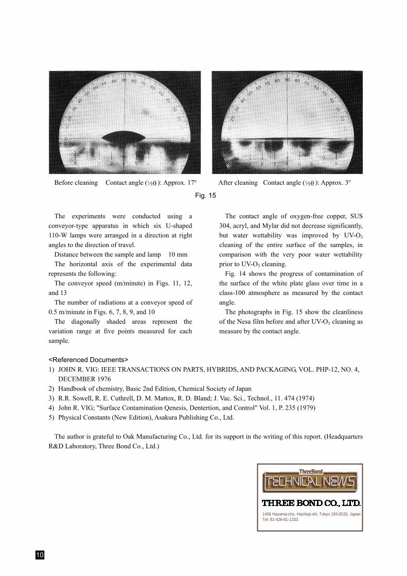
Before cleaning Contact angle (
1 θ 2 ): Approx. 17° After cleaning Contact angle ( 1 θ 2 ): Approx. 3°
Fig. 15
The experiments were conducted using a conveyor-type apparatus in which six U-shaped 110-W lamps were arranged in a direction at right angles to the direction of travel.
Distance between the sample and lamp 10 mm The horizontal axis of the experimental data
represents the following: The conveyor speed (m/minute) in Figs. 11, 12,
and 13 The number of radiations at a conveyor speed of
0.5 m/minute in Figs. 6, 7, 8, 9, and 10 The diagonally shaded areas represent the
variation range at five points measured for each sample.
The contact angle of oxygen-free copper, SUS 304, acryl, and Mylar did not decrease significantly, but water wettability was improved by UV-O3 cleaning of the entire surface of the samples, in comparison with the very poor water wettability prior to UV-O3 cleaning.
Fig. 14 shows the progress of contamination of the surface of the white plate glass over time in a class-100 atmosphere as measured by the contact angle.
The photographs in Fig. 15 show the cleanliness of the Nesa film before and after UV-O3 cleaning as measure by the contact angle.
<Referenced Documents> 1) JOHN R. VIG: IEEE TRANSACTIONS ON PARTS, HYBRIDS, AND PACKAGING, VOL. PHP-12, NO. 4,
DECEMBER 1976 2) Handbook of chemistry, Basic 2nd Edition, Chemical Society of Japan 3) R.R. Sowell, R. E. Cuthrell, D. M. Mattox, R. D. Bland; J. Vac. Sci., Technol., 11. 474 (1974) 4) John R. VIG; "Surface Contamination Qenesis, Dentertion, and Control" Vol. 1, P. 235 (1979) 5) Physical Constants (New Edition), Asakura Publishing Co., Ltd.
The author is grateful to Oak Manufacturing Co., Ltd. for its support in the writing of this report. (Headquarters
R&D Laboratory, Three Bond Co., Ltd.)