Embed Size (px)
Citation preview

Chalmers University of Technology
University of Gothenburg
Department of Computer Science and Engineering Göteborg, Sweden, August 2014
Threat Modelling and Risk Assessment Within Vehicular Systems
Master of Science Thesis in Computer Systems and Networks
Sathya Prakash Kadhirvelan
Andrew Söderberg-Rivkin

The Author grants to Chalmers University of Technology and University of Gothenburg
the non-exclusive right to publish the Work electronically and in a non-commercial
purpose make it accessible on the Internet.
The Author warrants that he/she is the author to the Work, and warrants that the Work
does not contain text, pictures or other material that violates copyright law.
The Author shall, when transferring the rights of the Work to a third party (for example a
publisher or a company), acknowledge the third party about this agreement. If the Author
has signed a copyright agreement with a third party regarding the Work, the Author
warrants hereby that he/she has obtained any necessary permission from this third party to
let Chalmers University of Technology and University of Gothenburg store the Work
electronically and make it accessible on the Internet.
Threat Modelling and Risk Management
Within Vehicular Systems
Prakash Kadhirvelan, Sathya
Söderberg-Rivkin, Andrew
© Prakash Kadhirvelan, Sathya, August 2014.
© Söderberg-Rivkin, Andrew, August 2014.
Examiner: Olovsson, Tomas
Chalmers University of Technology
University of Gothenburg
Department of Computer Science and Engineering
SE-412 96 Göteborg
Sweden
Telephone + 46 (0)31-772 1000
Cover: The truck found in the image above was provided from the HEAVENS project
referenced throughout the paper and is used in accordance to the project’s image license
agreement.
Department of Computer Science and Engineering
Göteborg, Sweden August 2014
i
__________________________________________________________________________________
Abstract
Safety has always been one of the most paramount aspects within a vehicle whether it is a
passenger car or a commercial vehicle. All companies within the automotive industry have
strived to achieve this aspect to ensure a good reputation with its consumers. Security, however,
isn’t as imperative and has led to a new field of study. For a while, safety and security were
further away from each other than most would think. But now they are more intertwined than
ever before.
As new functionalities and technologies are introduced to the standard vehicle, security has now
become one aspect that cannot be ignored. Safety of the vehicle and the passenger is
dramatically increased with the right security measures put in place. With that said, new
processes, standards, methods and tools must be devised in order to evaluate the security and
safety of these software-intensive automotive electrical and/or electronic (E/E) systems.
The following report gives an in-depth analysis of various facets of a vehicular system from use
cases to assets, an analysis of current threat modeling and risk assessment methodologies, the
adaptations created to make these methodologies applicable to vehicular systems and a
comparison of each. From these described activities we have created a full intuitive process for
threat modeling and risk assessment to help with the security requirements needed within a
vehicular system.
Keywords: Threat modeling, Risk assessment, AUTOSAR, Security, Vehicular System

ii

iii
_______________________________________________________________________________________
Acknowledgements
We would like to thank our examiner from Chalmers University, Prof. Tomas Olovsson for his
continuous support throughout this process. We also wish to express our gratitude to our
supervisors at Volvo Group Trucks Technology, Dr. Mafijul Islam and Christian Sandberg, for
their time and assistance that made this project possible.
Sathya Prakash Kadhirvelan & Andrew Söderberg-Rivkin, Göteborg July 3, 2014

iv
Contents
1.Introduction ................................................................................................................................................................... 1
1.1 Literature Review .................................................................................................................................................. 1
1.2 Scientific Contribution ......................................................................................................................................... 2
1.3 Scope ........................................................................................................................................................................... 2
1.4 Report Outline ......................................................................................................................................................... 3
2.Taxonomy of Dependable and Secure Computing .................................................................................... 4
2.1 Security Attributes and Terms ......................................................................................................................... 4
2.1.1 Vulnerability .................................................................................................................................................... 4
2.1.2 Threat ................................................................................................................................................................. 4
2.1.3 Attack.................................................................................................................................................................. 4
2.1.4 Risk ...................................................................................................................................................................... 5
2.1.5 Asset .................................................................................................................................................................... 5
2.2 Threat Models ......................................................................................................................................................... 5
2.2.1 CIA Model .......................................................................................................................................................... 5
2.2.2 STRIDE Model ................................................................................................................................................. 5
2.3 Methodologies/Modeling Tools ....................................................................................................................... 7
2.3.1 Trike .................................................................................................................................................................... 7
2.3.2 OCTAVE ............................................................................................................................................................. 8
2.3.3 Microsoft’s SDL Threat Modeling......................................................................................................... 10
2.4 Risk Assessment Rating and Ranking ......................................................................................................... 12
2.4.1 DREAD model ............................................................................................................................................... 12
2.4.2 Common Vulnerability Scoring System (CVSS).............................................................................. 13
2.4.3 OWASP Risk Rating Methodology ....................................................................................................... 14
2.4.4 EVITA Model ................................................................................................................................................. 15
3.Related Technologies ............................................................................................................................................. 16
3.1 Standard Vehicular System ............................................................................................................................. 16
3.1.1 In-Vehicular Network and Communication .................................................................................... 16
3.1.2 AUTOSAR ....................................................................................................................................................... 18
3.2 Functional Safety ................................................................................................................................................. 18
3.2.1 IEC 61508 ...................................................................................................................................................... 18
3.2.2 ISO 26262 ...................................................................................................................................................... 19
3.3 Common Criteria ................................................................................................................................................. 19
v
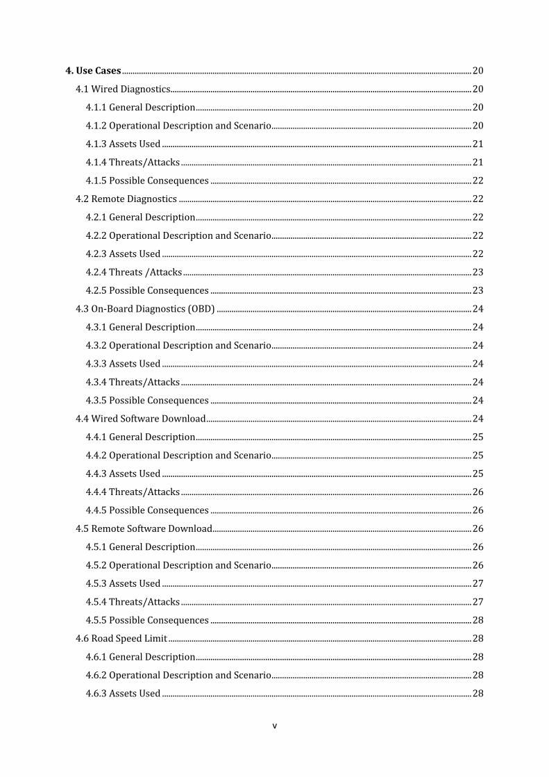
4. Use Cases ...................................................................................................................................................................... 20
4.1 Wired Diagnostics ............................................................................................................................................... 20
4.1.1 General Description ................................................................................................................................... 20
4.1.2 Operational Description and Scenario ............................................................................................... 20
4.1.3 Assets Used ................................................................................................................................................... 21
4.1.4 Threats/Attacks .......................................................................................................................................... 21
4.1.5 Possible Consequences ............................................................................................................................ 22
4.2 Remote Diagnostics ........................................................................................................................................... 22
4.2.1 General Description ................................................................................................................................... 22
4.2.2 Operational Description and Scenario ............................................................................................... 22
4.2.3 Assets Used ................................................................................................................................................... 22
4.2.4 Threats /Attacks ......................................................................................................................................... 23
4.2.5 Possible Consequences ............................................................................................................................ 23
4.3 On-Board Diagnostics (OBD) ......................................................................................................................... 24
4.3.1 General Description ................................................................................................................................... 24
4.3.2 Operational Description and Scenario ............................................................................................... 24
4.3.3 Assets Used ................................................................................................................................................... 24
4.3.4 Threats/Attacks .......................................................................................................................................... 24
4.3.5 Possible Consequences ............................................................................................................................ 24
4.4 Wired Software Download .............................................................................................................................. 24
4.4.1 General Description ................................................................................................................................... 25
4.4.2 Operational Description and Scenario ............................................................................................... 25
4.4.3 Assets Used ................................................................................................................................................... 25
4.4.4 Threats/Attacks .......................................................................................................................................... 26
4.4.5 Possible Consequences ............................................................................................................................ 26
4.5 Remote Software Download ........................................................................................................................... 26
4.5.1 General Description ................................................................................................................................... 26
4.5.2 Operational Description and Scenario ............................................................................................... 26
4.5.3 Assets Used ................................................................................................................................................... 27
4.5.4 Threats/Attacks .......................................................................................................................................... 27
4.5.5 Possible Consequences ............................................................................................................................ 28
4.6 Road Speed Limit ................................................................................................................................................ 28
4.6.1 General Description ................................................................................................................................... 28
4.6.2 Operational Description and Scenario ............................................................................................... 28
4.6.3 Assets Used ................................................................................................................................................... 28

vi
4.6.2 Threats/Attacks .......................................................................................................................................... 28
4.6.3 Possible Consequences ............................................................................................................................ 29
4.7 Data Logging ......................................................................................................................................................... 29
4.7.1 General Description ................................................................................................................................... 29
4.7.2 Operational Description and Scenario ............................................................................................... 29
4.7.3 Assets Used ................................................................................................................................................... 29
4.7.4 Threats/Attacks .......................................................................................................................................... 29
4.7.5 Possible Consequence .............................................................................................................................. 29
5.Use case Based Threat Models .......................................................................................................................... 31
5.1 Modeling Adaptation ......................................................................................................................................... 31
5.2 Use case: On-board diagnostics .................................................................................................................... 32
5.3 Use case: Road Speed Limit ............................................................................................................................ 33
6.Risk Assessment Adaptation .............................................................................................................................. 36
6.1 XML Parser ............................................................................................................................................................ 36
6.2 Risk Assessment Tool........................................................................................................................................ 36
6.2.1 Adaptation of CVSS .................................................................................................................................... 37
6.2.2 Adaptation of OWASP Methodology ................................................................................................... 38
6.2.3 Adaptation of EVITA Methodology ..................................................................................................... 39
6.2.3 Adaptation of HEAVENS Methodology .............................................................................................. 40
7.Evaluation and Results .......................................................................................................................................... 42
7.1 Evaluation: Automated vs. Manual – Threat Modeling ....................................................................... 42
7.2 Evaluation: Automated vs. Manual – Risk Assessment ....................................................................... 42
8.Discussion/Future Work ...................................................................................................................................... 44
9.Conclusion .................................................................................................................................................................... 45
Appendix A: Full SDL Process ................................................................................................................................ 47
Appendix B: Final Threat Models (All) ............................................................................................................. 47
References ........................................................................................................................................................................ 51
vi
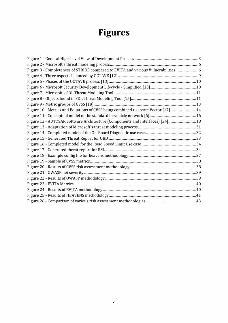
Figures
Figure 1 - General High-Level View of Development Process ......................................................................... 3
Figure 2 - Microsoft's threat modeling process ..................................................................................................... 6
Figure 3 - Completeness of STRIDE compared to EVITA and various Vulnerabilities .......................... 6
Figure 4 - Three aspects balanced by OCTAVE [12] ............................................................................................ 9
Figure 5 - Phases of the OCTAVE process [13] ................................................................................................... 10
Figure 6 - Microsoft Security Development Lifecycle - Simplified [13] .................................................... 10
Figure 7 - Microsoft's SDL Threat Modeling Tool .............................................................................................. 11
Figure 8 - Objects found in SDL Threat Modeling Tool [15] .......................................................................... 11
Figure 9 - Metric groups of CVSS [18]..................................................................................................................... 13
Figure 10 - Metrics and Equations of CVSS being combined to create Vector [17] ............................. 14
Figure 11 - Conceptual model of the standard in-vehicle network [6] ..................................................... 16
Figure 12 - AUTOSAR Software Architecture (Components and Interfaces) [24] ............................... 18
Figure 13 - Adaptation of Microsoft's threat modeling process .................................................................. 31
Figure 14 - Completed model of the On-Board Diagnostic use case .......................................................... 32
Figure 15 - Generated Threat Report for OBD .................................................................................................... 33
Figure 16 - Completed model for the Road Speed Limit Use case .............................................................. 34
Figure 17 - Generated threat report for RSL ........................................................................................................ 34
Figure 18 - Example config file for heavens methodology ............................................................................. 37
Figure 19 - Sample of CVSS metrics ......................................................................................................................... 38
Figure 20 - Results of CVSS risk assessment methodology ........................................................................... 38
Figure 21 - OWASP net severity ................................................................................................................................ 39
Figure 22 - Results of OWASP methodology ........................................................................................................ 39
Figure 23 - EVITA Metrics ........................................................................................................................................... 40
Figure 24 - Results of EVITA methodology .......................................................................................................... 40
Figure 25 - Results of HEAVENS methodology ................................................................................................... 41
Figure 26 - Comparison of various risk assessment methodologies ......................................................... 43

vii
Equations
Equation 1 - DREAD Algorithm for Risk Calculation ........................................................................................ 13
Equation 2 - Standard Risk Model Used for OWASP......................................................................................... 14
Equation 3 – Original CVSS Equation ...................................................................................................................... 37
Equation 4 – New equation adapted from CVSS................................................................................................. 37
Equation 5 - Adapted CVSS Equation Example ................................................................................................... 38

viii
List of Abbreviations
Abbreviations Description
AUTOSAR AUTomotive Open System Architecture
CAN Controller Area Network
CC Common Criteria
CIA Confidentiality, Integrity, Availability
CU Communication Unit
CIA Confidentiality, Integrity, Availability
CVSS Common Vulnerability Scoring System
DREAD Damage Potential, Reproducibility, Exploitability, Affected Users, Discoverability
ECU Electronic Control Unit
EVITA E-safety Vehicle Intrusion Protected Applications
CVSS Common Vulnerability Scoring System
OBD On-Board Diagnostic (Connection/Client)
OCTAVE Operationally Critical Threat, Asset, and Vulnerability Evaluation
WIFF Weaknesses, Idiosyncrasies, Faults, and Flaws

1
1
1.Introduction
As the technologies and functionalities grow within the automotive industry, two important
aspects within vehicular systems have become crucial factors in the vehicular system
development process: safety and security. The ability to detect certain threats and assess
specific risks within the ever-growing vehicular network has become the main subject for most
research and development departments within the automotive industry.
Electronic and embedded systems within vehicles are not new. However, systems that do inter
and intra-vehicular communication, whether they be new or old, are vulnerable to a wide range
of attacks. In order to provide the required mechanisms to assess threats and support security
within its networked infrastructure, new methods have to be provided. The problem at hand is
very similar to the problem which the IT industry has been facing for years, except that the
automotive industry hasn’t prepared for it [1], [2]. This can be attributed to processing power
and real-time constraints that are only apparent in vehicular systems. A vehicle is a safety
critical system, which means security exceptions are highly intolerable and can lead to loss of
life. Therefore, threat modeling and risk assessment have to become the foundation for
automotive security with respect to the standard IT security aspects.
The first step in designing the security for a system is to create a threat model of the system. A
threat model can be used to identify the assets that have to be protected, the kind of threats that
the assets might face, the classification of threats based on criticality and possible mitigations
against said threats.
The second step pertains to risk assessment of the defined threats. This is done to prioritize
which threats must be dealt with and what security requirements are needed to provide the
correct security to the system.
We reviewed the different areas of a vehicular system, analyzed various threat modeling and
risk assessment methodologies, adapted said methodologies to be applicable to vehicular
systems and evaluated our findings to create a full intuitive process to encapsulate these two
steps. The following report goes through these various activities to show how this process can
help with finding the security requirements needed for vehicular systems and their functions.
1.1 Literature Review Other processes for threat modeling (considered to be state-of-the-art) acted as a contribution
to our final model and modeling process i.e. [3], [4]. These modeling processes include those
from Microsoft such as STRIDE/DREAD, from EVITA [5] and others mentioned in the HEAVENS
project [6]. The EVITA and HEAVENS projects acted as a starting to point to this new field of
study. They were then coupled with modeling processes used within the standard IT

2
infrastructure, such as those mentioned before, in order to create a well-rounded modeling
process.
The state-of-the-art study [7] performed by the HEAVENS project indicate that “[s]ecurity design
and architecture has only been addressed to some degree in vehicular systems” and “internal
security is more or less absent.”
HEAVENS (HEAling Vulnerabilities to ENhance Software, Security and Safety) is a project led by
Volvo Groups ATR in collaboration with Chalmers and several industrial project partners. The
goal of this project is to reduce security vulnerabilities in embedded systems controlling most
vehicles. The results of our thesis work ended up acting as a contribution to a deliverable in the
HEAVENS project.
1.2 Scientific Contribution Since this can be considered a relatively new field, the scope of this work started from the very
beginning of the threat modeling process and ended with a well-endowed contribution to on-
going research for security within vehicular E/E systems.
This thesis project continued to advance the works carried out by the aforementioned HEAVENS
project and can be seen in the following step-by-step procedure that was taken to reach our final
conclusions:
Identify state-of-the-art concepts, techniques, and tools in relation to both threat and
risk modeling.
Investigate the applicability of existing concepts, techniques and tools in the context of
securing the automotive E/E systems
o ISO 26262
o EVITA (E-safety Vehicle Intrusion proTected Application (EVITA) [5]
Develop methods and tool support for both threat modeling and risk assessment
o Gather described use cases from requirement specifications [6]
o Identify possible Assets, Threats and Attacks
o Develop a Model based on the obtained data
Ideally the Model should be usable by the design team and Management
team to decide on what level of security they want to provide
1.3 Scope We feel that it is important that a visual description of the scope of work that was done should
be presented. In Figure 1 we show a general process for development of functionalities for
vehicular systems:

3
FIGURE 1 - GENERAL HIGH-LEVEL VIEW OF DEVELOPMENT PROCESS
In the normal instance, a function or use case is placed into what we consider a “black box” for
testing. Within this box is our threat modeling and risk assessment. From these tests, we should
be able to get some results that would help with our security requirements for the function. The
scope of our work pays close attention to the internal workings of the “black box” where we are
testing the functionality for any issues in security.
The function and use case part has already been done. The goal for this project was to complete
the threat modeling and risk assessment process as well as make the process as intuitive as
possible in order to provide output that could be utilized to determine the best security
requirements for all functions present (or in development) within a vehicular system.
All mitigation mechanisms and/or security protocols can be the next step to our already
completed project.
1.4 Report Outline This report contains 9 chapters with multiple sections in each to support our work. Chapter 1
gives an introduction and background to the work that was performed for this thesis. Chapter 2
focuses on the taxonomy of dependable and secure computing used throughout the project.
Chapter 3 gives the reader an in-depth view of some of the related technologies that were
considered to define our process and Chapter 4 goes through the seven use cases utilized.
Chapter 5 introduces our modeling adaptation and the final models that were created. Chapter 6
goes through the risk assessment adaptations and tool that were made and Chapter 7 evaluates
our results for both parts of the final process. Chapter 8 gives a brief discussion about the
research along with the work done to complete the project and finally, Chapter 9 is a brief
conclusion about everything within the thesis project.
Function/Use case
Black box
Threat Modeling
Risk Assessment
Security Requirements
Mitigation Mechanisms
Extra Security Protocols

4
2
2.Taxonomy of Dependable and
Secure Computing
Before we get into the work that has been done for this project, a better understanding of
security attributes in the standard computer system, threat models, methodologies along with
their respective tools and risk assessment rating is needed. This way the reader has a better
knowledge of these concepts in order to comprehend the uses and adaptations later in the
paper.
2.1 Security Attributes and Terms During this project we focused on four major security attributes that directly relate to the
normal computer system and that can be applied to the vehicular system.
2.1.1 Vulnerability
Vulnerability is seen as a weakness in the system which allows an attacker to reduce or
completely remove the system’s information assurance [8]. The system’s information assurance
is directly related to the CIA (Confidentiality, Integrity and Availability) model which is brought
up later in Section 2.2.1. These three aspects of this model are described below:
1. Confidentiality – Definition and enforcement of appropriate access levels for
sensitive information.
2. Integrity – Protection of data from being modified or deleted by an
unauthorized party and ensuring that authorized changes that should not have
been made can be undone.
3. Availability – Ensures that access to all resources that are needed to provide
information are always available.
2.1.2 Threat
A threat is seen as a possible danger that could exploit the above-mentioned vulnerabilities. It
can be seen as either intentional or accidental [8]. An intentional example would be an attacker
sending malicious code to the system to cause a denial of service, while an accidental threat can
be related to any natural disaster that could cause physical hard to the system.
2.1.3 Attack
An attack is an attempt to destroy, expose, alter, or steal information within the system. It is also
defined as an attempt to gain unauthorized use of a system and/or disable the use of said system
[8].

5
2.1.4 Risk
A risk is the likelihood and impact of a possible threat or attack [8]. This concept will be brought
up again once we go into the various risk assessment rating methodologies in Section 2.4.
2.1.5 Asset
An asset within a system can be data, a device, or any other component that supports
information related activities [8]. This is an important aspect to consider since an entire system
is made up of various assets that have to be considered when dealing with overall security.
2.2 Threat Models It is important to note that threat modeling and risk assessment multiple processes that occur at
different times. A threat model describes security aspects with respect to a particular kind of
system by associating a set of potential vulnerabilities, threats and attacks while keeping in mind
the potential set of assets incorporated with specific functions or use cases.
Assets play an important role when considering the possible threats to a particular system.
Without a set of target assets for the system, threats cannot exist within that system. At the same
time, however, without assets, there’s a possibility that there is no system to.
Risk assessment is normally done after the threat modeling process in order to map each threat
to either a mitigation mechanism or to an assumption that is not worth worrying about in
certain contexts.
In the upcoming sections, we go through the various threat models that are currently available
to us and go through a number of factors that lead to a general conclusion of each one.
2.2.1 CIA Model
Most security experts are familiar with this particular model as it is the basis for describing the
most important security aspects of a system. The CIA (Confidentiality, Integrity and Availability)
model gave us a foundation on which we were able to extend on in order to create a more
detailed threat modeling system.
2.2.2 STRIDE Model
The STRIDE model is an alternative approach to threat modeling that was proposed by
Microsoft. In this model, threats are categorized by the goals and purposes of the attacks. By
using these categories of threats, one has the ability to create a security strategy for a particular
system in order to have planned responses and mitigations to threats or attacks. The name
STRIDE is based on of the initial letter of possible threats [9].
1. Spoofing – attackers pretend to be someone or something they are not
2. Tampering – attackers change data in transit or in a data store
3. Repudiation – attackers perform actions that cannot be traced
4. Information disclosure – attackers gain access to data in transit or in data
store that they shouldn’t have access to
5. Denial of service – attackers interrupt normal operation of the system
6. Elevation of privilege – attackers perform actions they are not authorized to
perform
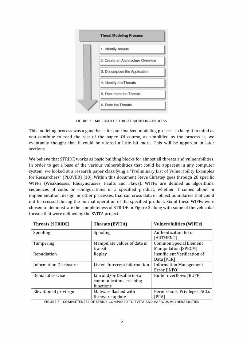
With the possible threats in mind, Microsoft proposed a modeling process. This can be seen in
Figure 2 below.
6
FIGURE 2 - MICROSOFT'S THREAT MODELING PROCESS
This modeling process was a good basis for our finalized modeling process, so keep it in mind as
you continue to read the rest of the paper. Of course, as simplified as the process is, we
eventually thought that it could be altered a little bit more. This will be apparent in later
sections.
We believe that STRIDE works as basic building blocks for almost all threats and vulnerabilities.
In order to get a base of the various vulnerabilities that could be apparent in any computer
system, we looked at a research paper classifying a “Preliminary List of Vulnerability Examples
for Researchers” (PLOVER) [10]. Within this document Steve Christey goes through 28 specific
WIFFs (Weaknesses, Idiosyncrasies, Faults and Flaws). WIFFs are defined as algorithms,
sequences of code, or configurations in a specified product, whether it comes about in
implementation, design, or other processes, that can cross data or object boundaries that could
not be crossed during the normal operation of the specified product. Six of these WIFFs were
chosen to demonstrate the completeness of STRIDE in Figure 3 along with some of the vehicular
threats that were defined by the EVITA project.
Threats (STRIDE) Threats (EVITA) Vulnerabilities (WIFFs)
Spoofing Spoofing Authentication Error [AUTHENT]
Tampering Manipulate values of data in transit
Common Special Element Manipulation [SPECM]
Repudiation Replay Insufficient Verification of Data [VER]
Information Disclosure Listen, Intercept information Information Management Error [INFO]
Denial of service Jam and/or Disable in-car communication, crashing functions
Buffer overflows [BUFF]
Elevation of privilege Malware flashed with firmware update
Permissions, Privileges, ACLs [PPA]
FIGURE 3 - COMPLETENESS OF STRIDE COMPARED TO EVITA AND VARIOUS VULNERABILITIES
7
A better explanation of the vulnerabilities and how they can be related to their specified threats
can be seen here:
1. [AUTHENT] – the product does not properly ensure the user has proven their
identity This can lead to authentication bypass by spoofing
2. [SPECM] – using special elements for various activities such as injection
Tampering with data in order to allow data to pass through
3. [VER] – the product does not sufficiently verify the origin or authenticity of the
data Repudiation is imminent in this situation leading to threats such as
replay attacks
4. [INFO] - an information leak is the intentional or unintentional disclosure of
information that either (1) is regarded as sensitive within the product's own
functionality or (2) provides information about the product or its environment
that could be useful in an attack but is normally not available to the attacker
Information Disclosure threat apparent in the situation of listening or
intercepting
5. [BUFF] – Buffer overflows or overruns can become apparent in multiple levels.
Used to cause issues in memory is our main focus Some are known to cause
an asset causing a denial of service
6. [PPA] – Improper handling, assignment, or management of privileges
Leading, in turn, to the elevation of privilege threat in which an attacker can
flash various malicious software when he or she does not have privilege to a
particular asset
We mention these factors above to show how STRIDE can be applied not only to software and
vehicular systems but to a wide range of situations. This is why it was chosen for this project and
will be seen later in Section 5.
2.3 Methodologies/Modeling Tools Multiple modeling tools were considered for this project. During our search, three main factors
played a major role in deciding which tool should be used. As stated in the introduction and
Section 1.3, the full process should be intuitive so that it could be utilized by people in multiple
fields (not only cyber security). The tool should be the same along with being flexible in the
sense that it can be adapted to our purposes, and as thorough as possible with regards to the
basis of cyber security. Below is a brief description of each tool that was researched with some
small discussion details.
2.3.1 Trike
Trike was one of the few open-source options that were available to us. It acts as “a unified
conceptual framework for security auditing from a risk management perspective through the
generation of threat models, with an associated tool which is currently under heavy
development [11].” The methodology and the tools itself approach threat modeling from a
standard risk management perspective and focuses on the other side of the spectrum which
deals with threats. In order to generate a threat model, the process of creating a threat model
through Trike attempts to do the following [11]:

8
1. Ensure that the risk this system entails to each asset is acceptable to all
stakeholders, that is by consulting and asking the assistance of the
stakeholders themselves
2. Be able to tell if we have completed the above
3. Communicate what has been done and its effects to the stakeholders
4. Empower stakeholders to understand /reduce the risks to themselves and
other stakeholders implied by their actions within their domains
While generating the threat model for the system at hand, it is important to make sure that all
stakeholders understand the risks that are apparent to the system and educate them in
understanding the risks, threats and mitigations to those issues.
Trike uses four specific models which include most aspects of which have been used for our final
modeling process:
1. Requirements Model
a. Actors
b. Assets
c. Intended Actions
d. Rules
e. Actor-Asset-Action Matrix
2. Implementation Model
a. Intended Actions vs. Supporting Operations and the State Machine
b. Data Flow Diagrams
c. Use Flows
3. Threat Model
a. Threat Generation
b. Attacks, Attack Trees, and the Attack
c. Weaknesses
d. Vulnerabilities
e. Mitigations
f. Attack Libraries
4. Risk Model
a. Asset Values, Role Risks, Asset-Action Risks, and Threat Exposures
b. Weakness Probabilities and Mitigations
c. Vulnerability Probabilities and Exposures
d. Threat Risks
e. Using the Risk Model
While the trike methodology goes as in-depth as possible in order to ensure security within a
single system, it goes beyond the scope of this particular project. On another note, the tool itself
was about as tedious and meticulous as the methodology itself. During the course of this project,
we felt that the tool being used should be as intuitive as possible so that all users, not just
security experts should be able to determine possible threats to an implemented system.
2.3.2 OCTAVE
OCTAVE (Operationally Critical Threat, Asset, and Vulnerability Evaluation) “is a risk based
strategic assessment and planning technique for security” [12]. It is mainly known for being self-
9
directed. This means that people from a company or organization assume responsibility for
setting their own security strategy.
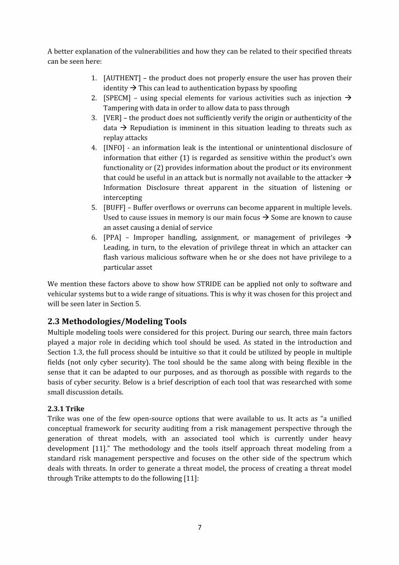
While most assessments of a system is focused on technology (targeted at technological risk and
focused on tactical issues), OCTAVE targets organizational risk and concentrates mainly on
strategic, practice-related issues. The evaluation methodology is flexible to accommodate most
organizations. It also utilizes not only people from the information technology department but
also those from operational (business) departments to address the security needs of the
organization as a whole. By doing so, the organization is able to balance three key aspects
applied to any network infrastructure: operational risk, security practices, and technology.
These can be seen how these aspects are applied in Figure 4:
FIGURE 4 - THREE ASPECTS BALANCED BY OCTAVE [12]
It is important to also note some of the key characteristics of the OCTAVE approach. For
example, OCTAVE is an asset-driven evaluation approach. Teams that analyze a specific system
or infrastructure:
1. Identify information-related assets that are important to the organization
2. Focus risk analysis on those assets judged to be most critical to the
organization
3. Consider the relationships among critical assets, threats to those assets, and
vulnerabilities that can expose the specified assets to threats
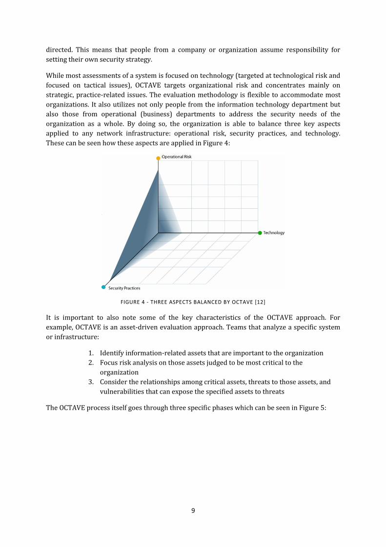
The OCTAVE process itself goes through three specific phases which can be seen in Figure 5:
10
FIGURE 5 - PHASES OF THE OCTAVE PROCESS [13]
From the basic description above, one can see that the OCTAVE methodology goes above and
beyond in order to secure any infrastructure. However, since it focuses mainly on the
organizational risk instead of technological risk, it isn’t something that can be easily applied to
most vehicular systems; not to mention the amount of paper-work, training, and practices that
goes into it.
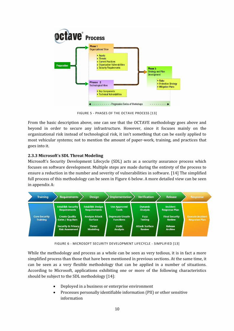
2.3.3 Microsoft’s SDL Threat Modeling
Microsoft’s Security Development Lifecycle (SDL) acts as a security assurance process which
focuses on software development. Multiple steps are made during the entirety of the process to
ensure a reduction in the number and severity of vulnerabilities in software. [14] The simplified
full process of this methodology can be seen in Figure 6 below. A more detailed view can be seen
in appendix A:
FIGURE 6 - MICROSOFT SECURITY DEVELOPMENT LIFECYCLE - SIMPLIFIED [13]
While the methodology and process as a whole can be seen as very tedious, it is in fact a more
simplified process than those that have been mentioned in previous sections. At the same time, it
can be seen as a very flexible methodology that can be applied in a number of situations.
According to Microsoft, applications exhibiting one or more of the following characteristics
should be subject to the SDL methodology [14]:
Deployed in a business or enterprise environment
Processes personally identifiable information (PII) or other sensitive
information
11
Communicates regularly over the internet or other networks
Any two out of the three characteristics can be applied to almost all functions or use cases within
vehicular systems and in some cases; all three have to be considered. To add onto the
applicability of SDL to vehicular system functions, Microsoft also provides a threat modeling tool
kit which is based on of the STRIDE model that has been mentioned in a Section 2.2.2.
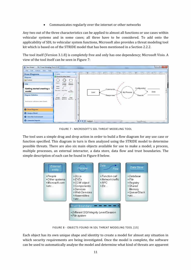
The tool itself (Version 3.1.8) is completely free and only has one dependency; Microsoft Visio. A
view of the tool itself can be seen in Figure 7:
FIGURE 7 - MICROSOFT'S SDL THREAT MODELING TOOL
The tool uses a simple drag and drop action in order to build a flow diagram for any use case or
function specified. This diagram in turn is then analyzed using the STRIDE model to determine
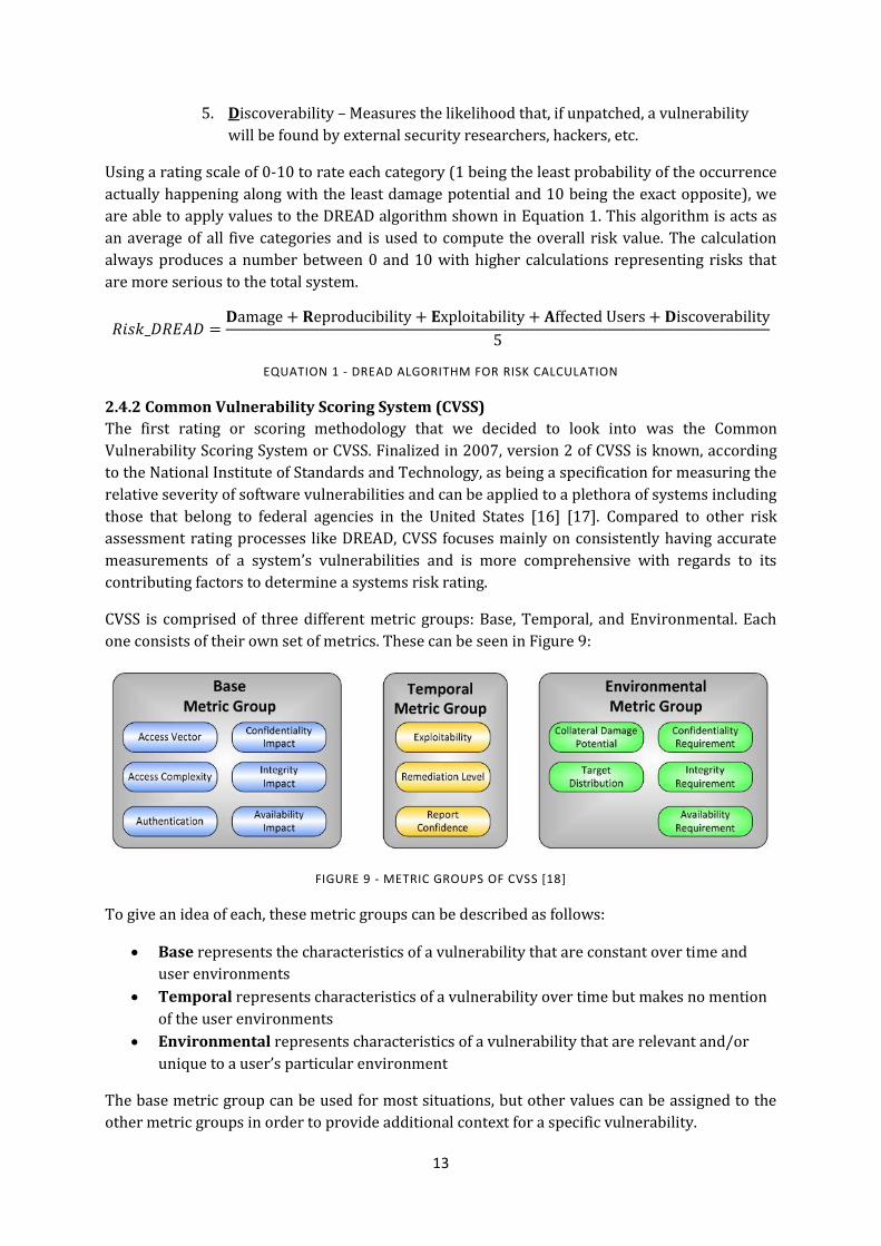
possible threats. There are also six main objects available for use to make a model; a process,
multiple processes, an external interactor, a data store, data flow and trust boundaries. The
simple description of each can be found in Figure 8 below.
FIGURE 8 - OBJECTS FOUND IN SDL THREAT MODELING TOOL [15]
Each object has its own unique shape and identity to create a model for almost any situation in
which security requirements are being investigated. Once the model is complete, the software
can be used to automatically analyze the model and determine what kind of threats are apparent

12
to the function or, in our case, use cases within the vehicular system. All analysis done is based
on the STRIDE model described earlier in Section 2.2.2. A manual assessment of what has been
found by the software can be done, other threats can be added if they are known to exist, and
mitigation processes can be included by security experts to the model itself. That is, if those
mitigation processes are already known or in practice.
The SDL threat modeling tool also allows for multiple layers, depending on how in-depth the
designer and security experts wish to go into a particular function. The context diagram is the
highest level in which we view the entire component, product or system depending on what is
being modeled. From there, we can go down into multiple levels to produce more detail. Level 1
can consist of a single feature or scenario, level 2 entails more low level description of detailed
sub-components of features and level 3 becomes even more detailed information of particular
components or features. It is rare to go any further in layers unless the size of the project is
considerably large or a large amount of trust boundaries are being used.
By using this methodology and tool, we were able to build flow diagrams for the use cases that
are described in Section 4 and determine the threats that are present using the STRIDE model.
Some adaptations and small changes were made to accommodate the process to standard
embedded vehicular systems. These changes are mentioned in the upcoming sections along with
a detailed description of the entire process taken to create correct threat models.
2.4 Risk Assessment Rating and Ranking As stated in Section 2.2, threat modeling and risk assessment are two processes that happen at
different times during the entirety of the process we are trying to create. There are a number of
risk assessment rating and processing methods currently in use. With these methods (and
methodologies), we were able to create a simple system that can determine the risk assessment
rating (or ranking) of each specified use case. These use cases are presented a little later, but it is
paramount to give the reader an understanding of each methodology we ended up deciding to
utilize. A brief introduction of each is found in the next two sub-sections.
2.4.1 DREAD model
Once threat modeling is complete, it is important to move onto risk assessment and analysis.
This is done in order to prioritize risks associated with specific threats. DREAD is also a
Microsoft model and acts as a classification scheme for quantifying along with comparing and
prioritizing the amount of risk presented by each threat that has been evaluated. Just like
STRIDE, DREAD is an acronym created by the initial letter of each category, but instead of
possible threats, each is a category of risk analysis. This can be seen below [9].
1. Damage potential – Ranks the extent of damage that occurs if a vulnerability is
exploited
2. Reproducibility – Ranks how often an attempt at exploiting a vulnerability
really works
3. Exploitability – Assigns a number to the effort required to exploit the
vulnerability. This also considers the preconditions such as whether the user
must be authenticated
4. Affected users – A value characterizing the number of installed instances of the
system that would be affected if an exploit became widely available
13
5. Discoverability – Measures the likelihood that, if unpatched, a vulnerability
will be found by external security researchers, hackers, etc.
Using a rating scale of 0-10 to rate each category (1 being the least probability of the occurrence
actually happening along with the least damage potential and 10 being the exact opposite), we
are able to apply values to the DREAD algorithm shown in Equation 1. This algorithm is acts as
an average of all five categories and is used to compute the overall risk value. The calculation
always produces a number between 0 and 10 with higher calculations representing risks that
are more serious to the total system.
EQUATION 1 - DREAD ALGORITHM FOR RISK CALCULATION
2.4.2 Common Vulnerability Scoring System (CVSS)
The first rating or scoring methodology that we decided to look into was the Common
Vulnerability Scoring System or CVSS. Finalized in 2007, version 2 of CVSS is known, according
to the National Institute of Standards and Technology, as being a specification for measuring the
relative severity of software vulnerabilities and can be applied to a plethora of systems including
those that belong to federal agencies in the United States [16] [17]. Compared to other risk
assessment rating processes like DREAD, CVSS focuses mainly on consistently having accurate
measurements of a system’s vulnerabilities and is more comprehensive with regards to its
contributing factors to determine a systems risk rating.
CVSS is comprised of three different metric groups: Base, Temporal, and Environmental. Each
one consists of their own set of metrics. These can be seen in Figure 9:
FIGURE 9 - METRIC GROUPS OF CVSS [18]
To give an idea of each, these metric groups can be described as follows:
Base represents the characteristics of a vulnerability that are constant over time and
user environments
Temporal represents characteristics of a vulnerability over time but makes no mention
of the user environments
Environmental represents characteristics of a vulnerability that are relevant and/or
unique to a user’s particular environment
The base metric group can be used for most situations, but other values can be assigned to the
other metric groups in order to provide additional context for a specific vulnerability.

14
Once each of these base metrics is assigned values, the base equation calculates a score that
ranges from 0 to 10. If a temporal or environmental score is needed, then the temporal equation
will combine the temporal metrics with the base score that was produced from the base metrics.
This works the same way in terms of the environmental score; however, the environmental
equation is combined with temporal score that was produced. From these factors, a vector is
created from the equation which facilitates the “open” nature of the framework. The vector is
outputted as a string of text that contains values assigned to each metric in order to
communicate exactly how the score, for each vulnerability found, is derived. The full process can
be seen in Figure 10:
FIGURE 10 - METRICS AND EQUATIONS OF CVSS BEING COMBINED TO CREATE VECTOR [17]
While this whole process was used in our final results, some adaptations of the process were
made and described in Section 6.2.1.
2.4.3 OWASP Risk Rating Methodology
The OWASP risk rating methodology is based on a number of different risk assessment
methodologies. CVSS and DREAD are two that have contributed to it. However, this methodology
is actually adaptable and applicable to most organizations and/or systems. Therefore, after
reviewing it on a number of different test cases that have been done in the past, we felt that it
would be a beneficial methodology to our project.
OWASP starts with the standard risk model, as seen in Equation 2, which includes the likelihood
and impact of a particular risk:
EQUATION 2 - STANDARD RISK MODEL USED FOR OWASP
It then uses 6 simple steps that include the factors that make up the “likelihood” and “impact” of
each risk. From there the tester is able to combine all 6 steps in order to determine the severity
of a particular risk to their system. The six steps are as follows [19]:
Step 1: Identify Risk
Step 2: Factors for estimating likelihood
o Threat Agent Factors
o Vulnerability Factors

15
Step 3: Factors for estimating impact
o Technical Impact Factors
o Business Impact Factors
Step 4: Determining severity of risk
o Informal Method
o Repeatable Method
o Determining Severity
Step 5: Deciding what to fix
Step 6: Customizing your risk rating model
Our main reason for considering this methodology is how it accommodates a good amount of
other methodologies and by how it estimates both technical and business impact factors. These
are two impact factors that should be present when considering the automotive industry and the
vehicles that it produces.
More information and a detailed description can be found in [19]. We don’t go into too much
detail here about the process, but give a more in-depth view of it later when adapting the
methodology to our purposes.
2.4.4 EVITA Model
EVITA (E-safety vehicle intrusion protected applications) is another project that went on for a
little over 3 years (2008-2011). Within this project, a model for performing risk analysis was
proposed to assess not only the risk associated with an attack but also the severity of the
possible outcome for stakeholders, and the probability that such an attack can be successfully
done [5]. This allows us to incorporate other elements into the risk rating scheme that should be
apparent within the automotive industry.

16
3
3.Related Technologies
Before moving on to the complete report, it is important to bring up some basic background and
components that are relevant to the project itself.
3.1 Standard Vehicular System Each manufacturer has their own implementation that goes into their vehicular system.
However, most systems consist of the same components and are built within the same type of
infrastructure. This section gives a high level view of a standard vehicular system to ease the
understanding of concepts later within the report.
Figure 11 shows a conceptual diagram of a typical in-vehicle network. While only being a
conceptual diagram, it gives a good view of the system that readers can use to understand later
concepts within this report:
FIGURE 11 - CONCEPTUAL MODEL OF THE STANDARD IN-VEHICLE NETWORK [6]
It is important to note that the scope of this project only pertains to that of the controller area
network (CAN) which is briefly described in the section below. The two sections following 3.1.1
pertain to that of the electronic control units (ECU) and on-board diagnostic connection (OBD).
The wireless gateway and internet features were not considered during the duration of this
project as they are considered to be external to the vehicle's network.

17
3.1.1 Controller Area Network (CAN)
Over the last few years, a number of different communication solutions have been presented to
the common vehicular system. As can be seen in Figure 11 above, the three main solutions are
LIN, MOST and CAN. The controller area network (or CAN) bus is the most popular and
standardized bus used today.
CAN itself is a serial bus system with multi-master capabilities. All CAN nodes have the ability to
transmit data and several CAN nodes can request the bus at the same time. This makes this serial
bus system one that is the subject of the ISO11898 international standard. It is also important to
note that there is no addressing of other receivers or stations. Instead, a transmitter will send
out a message to all other nodes (broadcast) and each node decides to process the message or
not based on the messages identifier [20]. OEM's and other companies have created other
implementations of CAN, however, which include either a sender or receiver address or both. An
example of this is found In J1939, the standard used by commercial vehicles for CAN
communication where the source address of the sender node is used as the least significant byte
of the CAN ID [21].
With its real-time properties and small packet format, CAN acts as a low-cost implementation for
vehicular networks. However, these properties also make this type of network vulnerable.
3.1.2 Electronic Control Units/Communication Units
The electronic control units (or ECUs) are the most prominent part of the standard vehicular
network. Originally added to the entire system to increase functionality within a vehicle, it has
been noted that in order to satisfy requirements (mainly due to strict legislation) placed on any
future vehicle, these ECUs must be networked in some way and that the implementation of these
functions should be distributed throughout these units [22]. An ECU can vary from a standard
switch point to a component that controls the anti-lock breaking system. An ECU is what we see
as either a communication node or subsystem node within a very compact, yet complex network
infrastructure. The ECU will play a major part within the models created at the end of this
project.
While the ECU is involved with everything inside the vehicular network, the communication unit
(or CU) takes care of communication outside the vehicle. All information from either the user
within the vehicle or the OEM back-office will go through this CU in order to reach the internal
network of the vehicle. The specificities of how the unit works will become apparent when use
cases are described in Section 4.
3.1.3 On-board Diagnostics (OBD)
For every trip made to the mechanic, it is important that information can be retrieved from the
vehicle to ensure the best quality of service done to the vehicle. With that in mind, we felt it
necessary to bring up the on-board diagnostic connection and client.
The on-board diagnostic connection and client act as a typical gateway to access the vehicle's
diagnostic information for the entirety of its networked infrastructure. The OBD connection
itself can be seen in Figure 11. More information about the OBD client and how it works is
presented in Section 4.3.
18
3.1.4 AUTOSAR
Originally launched as a development partnership in 2003 between manufacturers, suppliers
and other companies(in the electronics, semiconductor and software industries), the objective of
this global cooperation was to establish an industry standard in the field of automotive software
architecture [23],[24]. As of 2012, surveys have shown that this architecture is “the global
automotive software standard” [25].
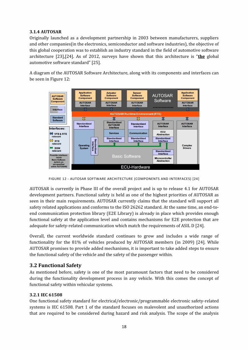
A diagram of the AUTOSAR Software Architecture, along with its components and interfaces can
be seen in Figure 12:
FIGURE 12 - AUTOSAR SOFTWARE ARCHITECTURE (COMPONENTS AND INTERFACES) [24]
AUTOSAR is currently in Phase III of the overall project and is up to release 4.1 for AUTOSAR
development partners. Functional safety is held as one of the highest priorities of AUTOSAR as
seen in their main requirements. AUTOSAR currently claims that the standard will support all
safety related applications and conforms to the ISO 26262 standard. At the same time, an end-to-
end communication protection library (E2E Library) is already in place which provides enough
functional safety at the application level and contains mechanisms for E2E protection that are
adequate for safety-related communication which match the requirements of ASIL D [24].
Overall, the current worldwide standard continues to grow and includes a wide range of
functionality for the 81% of vehicles produced by AUTOSAR members (in 2009) [24]. While
AUTOSAR promises to provide added mechanisms, it is important to take added steps to ensure
the functional safety of the vehicle and the safety of the passenger within.
3.2 Functional Safety As mentioned before, safety is one of the most paramount factors that need to be considered
during the functionality development process in any vehicle. With this comes the concept of
functional safety within vehicular systems.
3.2.1 IEC 61508
One functional safety standard for electrical/electronic/programmable electronic safety-related
systems is IEC 61508. Part 1 of the standard focuses on malevolent and unauthorized actions
that are required to be considered during hazard and risk analysis. The scope of the analysis

19
normally includes all relevant safety lifecycle phases [6]. It is important to note however that IEC
61508 does not address security or any intentionally malicious activities as stated by the
following:
1. Cover the precautions necessary to prevent unauthorized persons who
damage and/or adversely affect the functional safety of the E/E/P safety-
related system [6]
2. Specify requirements for the development, implementation, maintenance,
and/or operation of any security policies or security services therein needed
to meet a required security policy specified by the E/E/P safety-related
system. [6]
3.2.2 ISO 26262
ISO 26262 is another functional safety standard created in 2011 that is an adaptation of IEC
61508. It specifies the needs specific to the application sector of electrical and/or electronic
(E/E) systems within road vehicles. Unlike IEC 61508, which states that it does not address
security issues, ISO 26262 does not even mention if it addresses or does not address security
issues (even though it is an adaptation)[6].
3.3 Common Criteria The Common Criteria for information technology security evaluation, provides a common set of
requirements for security functionality of IT products. It also supplies these requirements for
measuring the assurance applied to these IT products during a security evaluation. The IT
products mentioned can be implemented within hardware, firmware or software [25].
One important part of the Common Criteria is that it addresses the protection of assets from the
three main security attributes mentioned in 3.2.1 and it is applied to the standard vehicular
system on many occasions [5][6].

20
4
4. Use Cases
Use cases from the automotive industry were investigated in order to create the threat models
for this project. Each one found below is described in greater detail within the HEAVENS and
EVITA deliverables found in [5] and [6]. Please note that all sections that state the possible
threats, attacks and consequences are derived from these deliverables.
4.1 Wired Diagnostics The following section presents an overall description of the wired diagnostics use case.
4.1.1 General Description
This use case is used for reading diagnostic trouble codes (DTC), reading/writing ECU data
parameters, reading ECU log data, perform software downloads to update firmware etc., or fulfill
proprietary manufacturer functions.
In order to perform the service itself, the vehicle is brought into a shop or dealer that is
authorized to run the process. A diagnostic tool is connected with a cable to the diagnostic
connector in the vehicle. This diagnostic connector is also known as the on-board diagnostic
(OBD) tool (Section 5.1.3).
All services that deal with diagnostics can have restricted access for security, emissions or safety
reasons. Other diagnostic services, such as software download and the reading or writing of data
to or from an ECU is typically restricted no matter what the reason.
Normally a challenge-response type of authentication is used. The specifications of this can be
seen in ISO 14229. The authentication service is known as SecurityAccess and can be found in
the latest description of ISO 14229-1:2013 [27].
In several markets and countries, it is a requirement that law enforcement should be able to
connect a universal tool to a vehicle to check various values from the controlling ECU. This could
be emission levels, DTCs, OBD monitoring test results, and so on. This universal tool should be
available for anyone to use. Third party tools must also be able to connect to the vehicle and
interact with the values mentioned earlier.
4.1.2 Operational Description and Scenario
In order to get a better idea of what happens during this use case, let’s take a look at a standard
scenario step-by-step.
The vehicle is brought into the shop for simple diagnostics during a yearly check, or the driver
notices something is wrong with the performance of the vehicle. The mechanic (our user in this
case) plugs his diagnostic tool into the vehicle using the diagnostic (OBD) connector. The
mechanic then starts his tool up, puts in his user authorization information if it is needed by the
21
tool and selects the function desired on the tool. Different diagnostic services are used
depending on the function that is requested on the tool by the mechanic.
For this example, let’s say that the mechanic wants to modify the road speed limit of the vehicle.
The tool determines which ECUs are affected, the parameter identifier (or memory location) and
if security access is required.
Once all of that is completed, the mechanic’s tool sends a request to the ECU to access the
memory location needed. The ECU will respond with a seed also known as the challenge to the
request. The tool calculates a key based on the seed received and sends the key back to the ECU.
The ECU validates the key and sends a success response back to the tool.
From there, the tool will request to read the current value of the original memory location
requested, for example, the value of the road speed limit parameter. The ECU responds with the
current value, the user or mechanic modifies the value, and the tool sends a request to write the
new value.
As long as all security requests have been met and everything has gone smoothly, the ECU will
write the value and send a success response to the tool. The ECU may also update the internal
checksums of its data based on the value change.
4.1.3 Assets Used
In this particular use case, we see that the affected ECU is involved along with the tool and tool
chain used to access it. The keys used to authenticate can also be considered an asset being used
in this use case as well.
4.1.4 Possible Threats/Attacks
From the general description and the described scenario, we can come down to a number of
possible threats or attacks that could affect the system.
With authentication not being present for all scenarios, there is a possibility of manipulating the
data or software within the ECU. This could cause a number of issues depending on what that
ECU is managing or handling in its daily routines. Without authentication or security present,
there is also the possibility of exploiting certain vulnerabilities or implementation errors either
in the ECU or the tool itself.
From the two threats described above, there is also the possibility of listening, intercepting,
altering, injecting or replaying data between the diagnostic tool and the vehicular system. Even
though this would probably have to include another type of connection to the system and the
ability to view traffic between the vehicle and the tool, it is a threat/attack that still has to be
seriously considered.
Denial of service is another threat against IT systems that can be apparent in vehicular systems.
Overloading the network with non-sense data and clogging up the communication channels
could deny service to the rest of the vehicular system.
Lastly, all parts of the STRIDE model from Microsoft can be applied to this situation.

22
4.1.5 Possible Consequences
Consequences should be the concern of most in the automotive industry. For example, in this
situation or scenario, a hacker could exploit vulnerabilities within the diagnostic service
implementation in order to open the ECU and reach other systems for further attacks. By doing
so, unauthorized access to the diagnostic services could put the vehicle’s integrity at risk. Certain
actions could be performed to alter the vehicles configuration, erase important data, cause
incorrect vehicle functionality, or control the vehicle’s functions. From what is stated above, it is
easy to realize the security and safety issues these consequences could create.
4.2 Remote Diagnostics Remote diagnostics is performed when the vehicle is not available to be brought into the service
station. A number of other factors set this use case apart from the previous section about wired
diagnostics.
4.2.1 General Description
As opposed to wired diagnostics, remote diagnostic services are defined by the OEM back-office
and delivered to the vehicle’s communication ECU. Instead of having a tool wired to the vehicle
to do the diagnostics and report its findings, the on-board diagnostic client connects to the
communication ECU (Section 5.1.1) to run services and report values to the OEM back-office. The
OBD client then connects to the in-vehicle network using the same diagnostic services as seen in
the wired diagnostic case. The only difference lies with the OBD client reporting its findings to
the communication ECU which in turn forwards the data to the OEM back-office.
All remote diagnostic services are defined in the OEM back-office and unlike wired diagnostic
services, it is not required by law to provide access to the remote diagnostic services to law
enforcement.
4.2.2 Operational Description and Scenario
The following gives a step-by-step scenario of remote reporting of data. The main entities of this
scenario go from the user performing the task to the ECU that reports values back to the user
requesting the information.
A user will first define a job by selecting the vehicle(s), data parameters or diagnostic trouble
codes that will be included and a start condition for the resulting report execution. The remote
diagnostic application then sends the specified job to the communication unit (CU). The ECU
implementing the execution of the job, in our case the on-board diagnostic client, will wait for
the necessary start conditions specified by the user to be fulfilled. Start conditions could relate to
a certain distance the vehicle has been running since the last report, a specific time of the year,
etc.
The OBD client will send a request to the affected ECUs to read the requested data. Challenge-
response techniques are done to ensure the security of the data being sent back and forth
between the OBD client and affected ECUs. Once everything is collected, the information is sent
on to the communication ECU and reported back to the OEM back-office.
4.2.3 Assets Used
In this instance, four assets are used in order for this process to complete successfully. The
software from the OEM back-office is used to connect to the communication ECU and request or
change certain values within the vehicular system. The communication unit (CU) is also a part of

23
the assets used in this situation. All communication is done on a wireless network
(802.11a/b/g/n, 3G, 4G, etc.). In the case of the tool or tool chain being used, we see the OBD
being the tool that communicates within the vehicle’s network and communicates all findings to
the communication ECU which in turn is sent to the OEM back-office. Lastly, keys are used
during this process when remotely accessing the vehicle’s communication ECU and when the
OBD client is accessing affected ECUs within the vehicular system.
4.2.4 Threats /Attacks
The threats and attacks that can be defined for wired diagnostics can also be applied to remote
diagnostics. There are certain aspects that are different, however.
The manipulation of data and software inside the ECU can be considered as a threat or attack
assuming that it is accessible from outside communications. There is one more step of possible
security due to the type of wireless connection used for accessing the communication unit.
Just as it was mentioned for wired diagnostics, there is the possibility of exploiting
vulnerabilities or implementation errors if any part of the system can be accessed.
Listening, intercepting, altering, injecting or replaying data between the vehicle and the
diagnostics tool also applies here, but this can also be applied to the outside communication
relays being done from the back-office to the communication unit of the vehicular system.
Lastly, denial of service and all parts of the STRIDE model can be applied.
4.2.5 Possible Consequences
As seen earlier within wired diagnostics, the same consequences can be applied to remote
diagnostics. A hacker could exploit vulnerabilities in the diagnostics service implementation,
thereby opening the ECU and vehicular system to further attacks.
Unauthorized accesses (Not OEM or workshop) to diagnostic services could also put vehicle
integrity at risk. This is also apparent to the situation with wired diagnostics as described
earlier. Remote attacks, however, have the possibility of being more severe as well. During the
process of wired diagnostics, the vehicle is at a standstill which would bring the safety aspect
down to a low standard. If remote attacks are possible, the attack could be done when the user is
unaware and the vehicle is in motion. Lastly, remote attacks, due to the remote diagnostic
design, can be done on a mass scale as wired diagnostics can be done only to the car it is
connected to.
The two main possible consequences within the remote diagnostics service that differ from
wired diagnostics are as follows:
A hacker or thief could jam the on-going session by denying access to the remote diagnostics
services. For example, since this use case has the ability of accessing most of the vehicular
system for predictive, preventive and corrective maintenance, a thief could block attempts to
shut down a stolen vehicle. The final consequence relates to the fact that remote diagnostics
functionality opens up new vulnerabilities. Because of the communications happening between
the OEM back-office and the vehicles communication unit, the remote diagnostics functionality
has to be considered a higher priority as compared to the situation with vehicles that only
support wired diagnostics.

24
4.3 On-Board Diagnostics (OBD) On-board diagnostics is an imperative use case to today’s vehicular system no matter what kind
of vehicle is being used. The ability to make sure that all peripherals and the entire system are
working correctly is one way to ensure safety and correct functionality for the driver and vehicle
itself. It is a very common use case within vehicles today.
4.3.1 General Description
A vehicle will perform its own diagnostics and reporting if it detects it is in a faulty state. In
order to do this, the vehicular system has what is called on-board diagnostics (OBD). The system
basically has the ability to use its instrument cluster to request and present information.
This is very useful in various situations such as requesting and presenting diagnostic trouble
codes, software identification for the affected ECUs, etc. This is normally done when the vehicle
is in a faulty state.
The main difference between this scenario, wired diagnostics and remote diagnostics is that no
diagnostics tool is needed to complete the process. Everything is done within the vehicular
system.
4.3.2 Operational Description and Scenario
Compared to the other use cases that have been described already, the on-board diagnostics use
case is considerably simpler due to the lack of related assets and minimal amount of process
steps. The following gives a brief explanation of a brief scenario example.
It all starts with the driver putting the vehicle in a state where on-board diagnostics is actually
possible, i.e. placing the key into the ignition. From there, the driver will perform a sequence of
button or lever activations. Once the information has been found from these steps, the selected
information will be presented within the instrument cluster.
4.3.3 Assets Used
In this situation, the only assets that have to be considered are the affected ECUs in which the
diagnostic information is stored and the information itself that is reported in the end. Since the
whole process is done within the vehicular system, no outside communication has to be done,
and the only authentication that should be done is to confirm that the data presented is
authentic or not manipulated in any way.
4.3.4 Possible Threats/Attacks
Denial of service is an apparent threat or attack for this use case. All parts of the STRIDE model
should also be considered despite the fact that the entire process is done within the vehicle
itself.
4.3.5 Possible Consequences
All consequences that could arise from this use case can vary at an extreme rate. For example, an
owner could block access to the OBD service or alter the data that comes from the service. By
doing so the owner could increase the sales value by stating that the vehicle is not in a faulty
state.
4.4 Wired Software Download ECUs and other components within the vehicle are always in an ever changing state as time goes
on. Therefore, an update for these components is needed as the vehicle becomes older.

25
4.4.1 General Description
In most vehicular systems, any ECU can be updated by replacing the software within it. This
procedure is normally done through a software download. This is normally done at workshops
during scheduled service to improve the overall functionality of the operation of the vehicle
itself.
Just like wired diagnostics, the wired software download is done using a diagnostic tool
connected to the diagnostic (OBD client) connector.
4.4.2 Operational Description and Scenario
The start to this process is much like that of the standard wired diagnostics. The user will plug
the tool into the vehicle using the diagnostic (OBD) connector and start the tool. User
authentication and authorization within the tool may be necessary depending on what kind of
information the tool can obtain or what changes it can make to the overall system.
The tool will then send a request for hardware and software identification to all ECUs within the
vehicle. From this request, the tool should receive part numbers, serial numbers, software
versions, etc. The tool then sends a request to the OEM back-office for available updates. Again,
in this instance, tool and user authentication may be required. The OEM back-office will then
present available updates.
In this case, let’s say the user wishes to update the vehicle’s main ECU. The tool will send a
request to the back-office for a programming package specifically for the vehicle’s main ECU.
This programming package is normally vehicle specific, meaning the package is adapted for a
certain vehicle configuration. The package also may contain blocks of data that have been signed
by the OEM to create a digital signature in order to validate the package.
The tool then moves by sending a request to the vehicle’s main ECU to switch to programming
mode. This is followed up by another request to the ECU for re-programming access in order to
flash new software onto the hardware. The ECU responds with a seed or challenge. The tool
calculates and sends a key in response to the challenge. All calculations are done based on the
seed that is received by the tool.
The ECU validates the key that is sent by the tool and responds if there is a successful connection
or not based on correct (or incorrect) authentication. If the connection is accepted, the tool will
then send a request to re-program certain memory blocks with new software. It will also send a
request to the ECU to perform standard programming checks. These checks can include
verification of digital signatures that have been generated by the downloaded software or data.
The ECU will respond with either a success or failure to these programming checks.
The tool sends a reset request to the ECU so that the new software that has been flashed to the
specified hardware can restart using the new software. The tool will then send a request for
hardware and software identification (serial numbers, version numbers, etc.) to the ECU that has
been re-programmed. If everything has gone smoothly, the ECU should respond to the tool with
its hardware information along with the new software identification caused by the update.
4.4.3 Assets Used
In the case of wired software downloads, three main assets are used for the process. The ECU
that is being updated along with the OBD client that forwards the requests and the tool or tool
chain that is used to complete the process.

26
4.4.4 Possible Threats/Attacks
With an increased possibility for accessing this particular use case, there are various threats and
attacks that are apparent that wouldn’t be with diagnostic processes.
Using a fake identity or impersonating an authenticated user cannot be overlooked. This can
happen during authentication processes between the user and the tool being used or the user’s
identity being confirmed by the OEM back-office. In conjunction with the previous threat or
attack, we have to consider the possibility of a fake tool being used as well.
If the attacks that deal in fake identity or a fake tool are possible, then we would also have to
consider the possibility of manipulating the data and/or software within the ECU.
As always, in most use cases that have been seen already, the possibility of exploiting a
vulnerability or implementation error is also valid in this use case.
Due to the amount of communication being done for this use case to complete, listening,
intercepting, altering, injecting and/or replaying data between the vehicle and diagnostic tool
has to be considered. In this situation, however, we also have to consider these possibilities in
conjunction with communication between the tool and the back-office as well.
Finally, as seen in previous use cases, there is also the possibility of a denial of service and
everything that is included within the STRIDE model.
4.4.5 Possible Consequences
From the threats and attacks that have been described in the previous section, there are
particular consequences that have to be documented.
An example would be downloading software that has been modified and not approved by the
OEM. This software can be used to bypass certain security features, report wrong sensor values
or to add more features to the car that would normally not be sold by the OEM. The main issue in
this particular consequence is that the data and software being downloaded to the vehicular
system is not being certified by the OEM.
4.5 Remote Software Download At some point in time, an update to a vehicles system may have to be done outside of the
dealership or workshop. That is where a remote software download is done.
4.5.1 General Description
The difference that is seen between this use case and that of wired software download is that no
physical access to the vehicle is needed. This increases the vehicles uptime and is a convenient
feature for the vehicle owner. We also see the communication unit (CU) playing one of the most
important roles in this process.
The process itself is defined by the OEM back-office, delivered to the vehicle’s CU and is executed
within the vehicle’s OBD client. All commands and requests are forwarded by the OBD client to
the affected ECUs.
4.5.2 Operational Description and Scenario
To start the process, the user will enter a remote software download application. User
authentication and authorization may be needed, but depends on the application or security
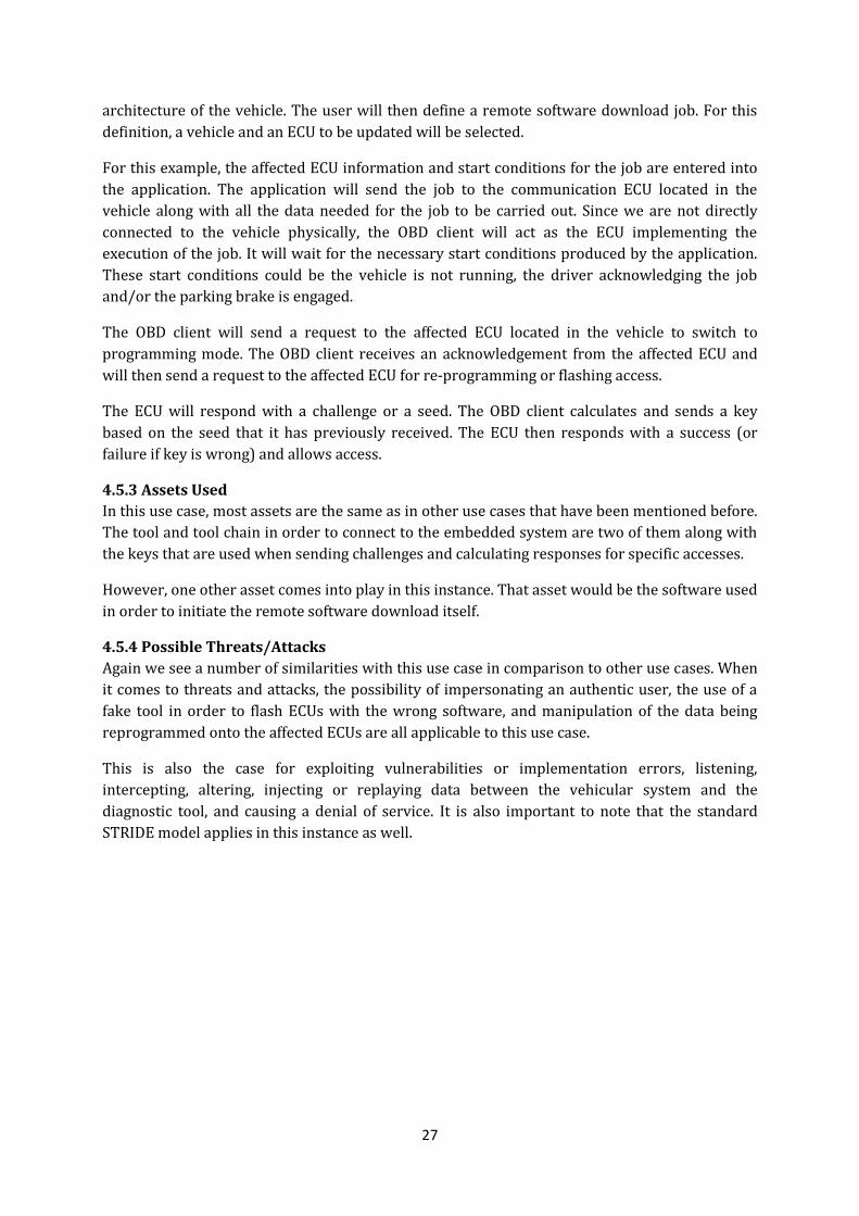
27
architecture of the vehicle. The user will then define a remote software download job. For this
definition, a vehicle and an ECU to be updated will be selected.
For this example, the affected ECU information and start conditions for the job are entered into
the application. The application will send the job to the communication ECU located in the
vehicle along with all the data needed for the job to be carried out. Since we are not directly
connected to the vehicle physically, the OBD client will act as the ECU implementing the
execution of the job. It will wait for the necessary start conditions produced by the application.
These start conditions could be the vehicle is not running, the driver acknowledging the job
and/or the parking brake is engaged.
The OBD client will send a request to the affected ECU located in the vehicle to switch to
programming mode. The OBD client receives an acknowledgement from the affected ECU and
will then send a request to the affected ECU for re-programming or flashing access.
The ECU will respond with a challenge or a seed. The OBD client calculates and sends a key
based on the seed that it has previously received. The ECU then responds with a success (or
failure if key is wrong) and allows access.
4.5.3 Assets Used
In this use case, most assets are the same as in other use cases that have been mentioned before.
The tool and tool chain in order to connect to the embedded system are two of them along with
the keys that are used when sending challenges and calculating responses for specific accesses.
However, one other asset comes into play in this instance. That asset would be the software used
in order to initiate the remote software download itself.
4.5.4 Possible Threats/Attacks
Again we see a number of similarities with this use case in comparison to other use cases. When
it comes to threats and attacks, the possibility of impersonating an authentic user, the use of a
fake tool in order to flash ECUs with the wrong software, and manipulation of the data being
reprogrammed onto the affected ECUs are all applicable to this use case.
This is also the case for exploiting vulnerabilities or implementation errors, listening,
intercepting, altering, injecting or replaying data between the vehicular system and the
diagnostic tool, and causing a denial of service. It is also important to note that the standard
STRIDE model applies in this instance as well.

28
4.5.5 Possible Consequences
To begin with, an attacker could jam on-going software downloads which could result in corrupt
software within all computerized units or cause a denial of service to the system. An attacker
could also download an older version of the systems software in order to use an already
exploited vulnerability that has been fixed in newer versions.
With unauthorized software downloaded, it is also possible for an attacker to reverse engineer the authentication process between the CU and the back office. This could lead to deriving keys for ECUs which could be later used on some other vehicles for devious purposes. It is also important to note that the remote software download functionality in the vehicle opens up new vulnerabilities compared to a vehicle supporting only wired software download/diagnostics.
4.6 Road Speed Limit Road speed limit is normally seen as one of the many uncommon use cases.
4.6.1 General Description
Road Speed Limit is a functionality provided by the manufacturer to not let the vehicle go
beyond a speed that is described by legislation or a fleet owner.
4.6.2 Operational Description and Scenario
A speed sensor transmits the current vehicle speed information to a tachograph (TACHO) in an
encrypted form. The tachograph sends the speed in a form of pulses to an RSL ECU where it is
converted to actual vehicular speed using pulse-to-speed conversion data which the tachograph
provides. The RSL ECU performs a comparison of the new limits sent by the fleet owner with its
current speed limit parameters and choses the lowest speed. The speed limit value is then sent
to the engine ECU where a comparison between its own RSL parameters and the parameters
sent by the RSL ECU is done. From there, the lowest road speed limit is selected. If the current
speed of the vehicle is higher than the selected RSL, then the fuel supply is cut from the engine to
bring the speed down to the correct parameters.
4.6.3 Assets Used
Speed Sensor, tachograph and RSL ECU (along with its parameters) are the intrinsic assets for
this use case. The engine ECU is an important extrinsic asset. Even though its main function is to
run the vehicle correctly, RSL could inherently cause issues to that main function. This is why it
is included in the assets used for this use case.
4.6.2 Possible Threats/Attacks
Tampering with the RSL parameters using third party tools is one way of attacking the RSL.
However, the downside is that the RSL parameters have to be changed in both the engine and
RSL ECUs because of the comparison done in the engine ECU. A more simplistic attack would be
to have a rogue ECU that has access to the CAN bus (perform man-in-the-middle attack) send
spoofed CAN messages with fake speed data to the engine ECU. This could make the engine ECU
think that the vehicle is going at a high speed when it is not, thereby resulting in a fuel supply
cut.

29
4.6.3 Possible Consequences
Once an attack is done and the RSL is set to a specific speed parameter, the consequences can
vary depending on the new values presented to the engine ECU. With an attack that presents
false values that are higher than the RSL parameters, the vehicle could be brought down to a
speed that is dangerous on most road ways. This could cause accidents and possible loss of life if
the fuel is cut abruptly.
On the other side of the spectrum, the RSL could be set to a higher value above the speed the
vehicle can actually achieve, thereby disabling the whole point of the function. If the driver is
used to going at the highest speed that RSL allows and the RSL value is changed to go to the
vehicles top speed, this could cause a sudden increase in speed which could lead to another
accident.
4.7 Data Logging Data logging is a feature that can be used for a number of different reasons. In the next few sub-
sections, however, we go through one main use case that this feature can be applied to.
4.7.1 General Description
Data Logging is used by fleet owners to keep track of a driver’s activity, which can be used to
provide incentives for drivers who drive efficiently. This makes the Data Logging use case a
lucrative target for the drivers.
4.7.2 Operational Description and Scenario
The telematics ECU queries the target ECU for log data periodically. Depending upon the
protection level enforced, it may have to follow the ISO14229 standard for authentication. The
obtained logs are transmitted to the back-office by the telematics ECU. The keys used for
challenge and response are stored on the telematics ECU.
4.7.3 Assets Used
The telematics ECU and the keys it stores are the basic assets in this use case. The telematics
ECU is also used for several other purposes which involve communication with the back-office. It
has access to the internal CAN bus and an external interface (802.11b/g/n, 3/4G, GSM).
4.7.4 Possible Threats/Attacks
Tampering with the telematics ECU for the keys to unlock ECUs for sensitive data is one way of
getting privileged access to a target ECU. Besides this, the communication between the
telematics ECU and a target ECU (whose logs has to be obtained) are done over CAN, which
means the data is visible to all the ECUs connected to the bus and it is vulnerable to man-in-the-
middle attacks. The same can be said for the external communication interface of the telematics
ECU too. Depending on the medium (802.11b/g/n or 3G or GSM) it uses to transmit the logs, it
can be vulnerable to eavesdropping or spoofing.
4.7.5 Possible Consequence
Considering that data logging is mainly used by fleet owners to monitor their drivers activities
for possible reward incentives, consequences for this use case are not critical. However, if used
by law enforcement agencies to conduct forensics, these logs can be very critical. The attacks can
be used to modify log information to gain rewards from fleet owners when they are earned or to
tamper with an investigation. The alternative collateral damage could be extracting the

30
ISO14229 unlock keys for specific ECUs so an attacker can gain elevated privileges in order to
access functions more vital to the overall vehicular system.

31
5
5.Use case Based Threat Models
To give a visual perspective on how the flow diagrams for use cases are made and how they are
applied to create our threat models, a couple of examples are given. All flow diagrams used to
determine possible threats and that contribute to the final threat model can also be reviewed
within appendix B.
The completed threat models presented were also those that were used to test the
aforementioned risk assessment tool.
5.1 Modeling Adaptation In Section 2.2.2, we described the STRIDE model used by Microsoft. Also included was Figure 2
which gives an overview of the modeling process proposed by Microsoft. While this is one good
way of determining a threat model, we believed that some changes and adaptations were
necessary. Our adapted process from what is displayed in Figure 2 can be seen in Figure 13:
FIGURE 13 - ADAPTATION OF MICROSOFT'S THREAT MODELING PROCESS
The process has not only been adapted for our purposes, but it has also been simplified. Some
parts of the process were merged and others were not necessary for the type of system that is
being investigated.
In order to create our threat model, we started with specific use cases and scenarios. The
overview of architecture found in Microsoft’s modeling process was ignored since doing a threat
model for the entire vehicular system seemed a little much when dealing with specific functions.
The step from Microsoft’s modeling process of decomposing the application was not needed
either. The use cases that were analyzed were done on a very high level and are considered to be
Use Cases/Scenarios
Identify Assets
Identify Threats
Document Threats

32
general functions rather than full applications. Identifying the assets came next as it is important
to know which assets are interacting with each other for the use case to carry out correctly. We
then identified and documented the threats that were found. Rating the threats (again found in
Microsoft’s modeling process) was not necessary as that would be done later within our risk
assessment process.
With the simple concept of utilizing the use cases that have been described in Section 4, we were
able to make simple flow diagrams which eventually were analyzed to become our finalized
threat models.
5.2 Use case: On-board diagnostics We first take a look at a common use case; one that can be found in most vehicular systems. By
using the use case description found in Section 4.3 and the Microsoft SDL toolkit, we were able
to create the use case flow diagram for on-board diagnostics found in Figure 14.
FIGURE 14 - COMPLETED FLOW DIAGRAM OF THE ON-BOARD DIAGNOSTIC USE CASE
From viewing the diagram above, it’s easy to discern exactly what happens during this use case.
The use case diagram was evaluated multiple times to ensure that it was complete and matched
the use case at its highest level.
Once the use case diagram was completed and no diagram validation errors were found, we
went ahead and allowed the SDL threat modeling tool to analyze the diagram based on the
STRIDE threat model. From the analyzed data, we were able to generate an overall report. This
can be seen in Figure 15 below:

33
FIGURE 15 - GENERATED THREAT REPORT FOR OBD
By using the STRIDE model, the SDL tool is able to determine where these threats could possibly
happen by analyzing each object whether it is an external interactor, data flow, process or data
store.
From the analysis and reports, we are able to determine what security requirements or
mitigations need to be added or implemented into the current vehicular system for the specified
use case.
5.3 Use case: Road Speed Limit Now we move on to a more complex use case in order to do an evaluation of how the tool
analyzes our various use case flow diagrams. For this instance, we look at the road speed limit
use case (RSL). As compared to the on-board diagnostics use case, RSL deals with not only the
internal network of the vehicle, but has to connect to other networks outside of the vehicle to
receive data from the OEM back-office or the fleet owner. The exact actions taken during this use
case can be reviewed in Section 4.6. The final use case flow diagram that was developed for this
use case can be seen in Figure 16 below:
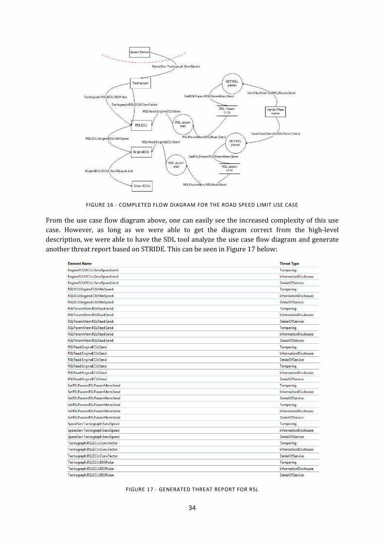
34
FIGURE 16 - COMPLETED FLOW DIAGRAM FOR THE ROAD SPEED LIMIT USE CASE
From the use case flow diagram above, one can easily see the increased complexity of this use
case. However, as long as we were able to get the diagram correct from the high-level
description, we were able to have the SDL tool analyze the use case flow diagram and generate
another threat report based on STRIDE. This can be seen in Figure 17 below:
FIGURE 17 - GENERATED THREAT REPORT FOR RSL

35
The above report does not cover everything due to the amount of information that it generates.
It has been reduced in order to fit on the page but also to give enough information to the reader
to understand what the program is evaluating.

36
6
6.Risk Assessment Adaptation
From the several Risk Assessment methodologies specified in section 2.4, we modified CVSS due
to the reasons described in section 6.2.1 and wrote a tool which implements CVSS, OWASP,
EVITA, and HEAVENS based on the output of SDL tool. The written tool can be split into two
parts as described in section 6.1 and 6.2; the first one being a parser program. The second is a
risk assessment tool that determines the risk rating based on the 4 risk assessment
methodologies mentioned above and outputs a table to compare them.
6.1 XML Parser The Microsoft SDL tool generates a file in XML format. The parser of our risk assessment tool
parses assets, threats, threat IDs and other useful meta-data generated by the SDL tool which in
turn is useful for the risk assessment process.
6.2 Risk Assessment Tool The risk assessment tool implements several risk assessment methodologies like CVSS
(adapted), OWASP, EVITA, and HEAVENS. The assets and threats list obtained from the parser is
used in conjunction with a configuration file.
The configuration file defines the metrics such as exposure, information about the target,
severity of an asset etc. required by different methodologies. An example configuration file is
shown in Figure 18; the risk assessment tool uses these metrics to implement the risk
assessment methodologies described in sub-section 6.2.1 to 6.2.4.
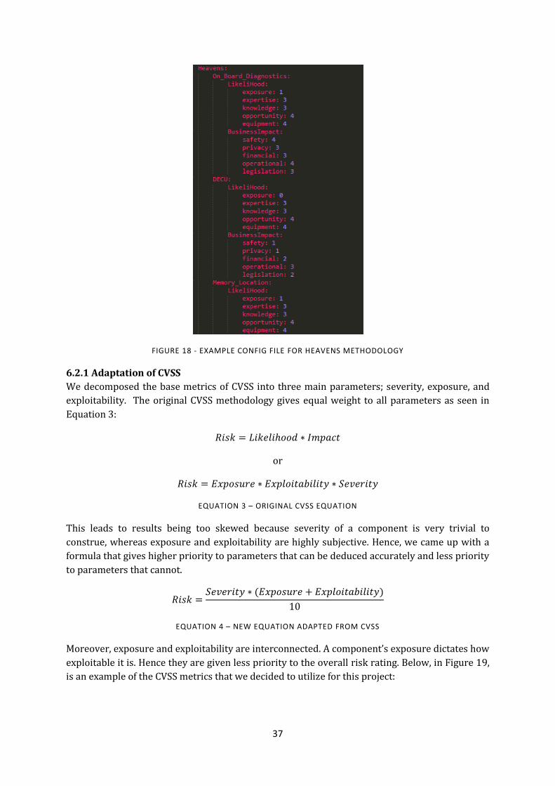
37
FIGURE 18 - EXAMPLE CONFIG FILE FOR HEAVENS METHODOLOGY
6.2.1 Adaptation of CVSS
We decomposed the base metrics of CVSS into three main parameters; severity, exposure, and
exploitability. The original CVSS methodology gives equal weight to all parameters as seen in
Equation 3:
or
EQUATION 3 – ORIGINAL CVSS EQUATION
This leads to results being too skewed because severity of a component is very trivial to
construe, whereas exposure and exploitability are highly subjective. Hence, we came up with a
formula that gives higher priority to parameters that can be deduced accurately and less priority
to parameters that cannot.
EQUATION 4 – NEW EQUATION ADAPTED FROM CVSS
Moreover, exposure and exploitability are interconnected. A component’s exposure dictates how
exploitable it is. Hence they are given less priority to the overall risk rating. Below, in Figure 19,
is an example of the CVSS metrics that we decided to utilize for this project:

38
FIGURE 19 - SAMPLE OF CVSS METRICS
Figure 20, shows the results of CVSS risk assessment methodology:
FIGURE 20 - RESULTS OF CVSS RISK ASSESSMENT METHODOLOGY
An example of the equation being used on threat ID 56 can be seen here. The values placed into
the equation are derived from the configuration file in Figure 19:
EQUATION 5 - ADAPTED CVSS EQUATION EXAMPLE
The adapted CVSS ratings are on a scale of 1 to 5. From the table one can see that, assets such as
Memory_Location that are the least exposed have a very low risk rating and assets such as DECU
which process more external data have a high risk rating.
6.2.2 Adaptation of OWASP Methodology
OWASP’s risk assessment methodology is a famous among web applications. It is maintained by
the OWASP community. This methodology considers 4 main factors; Threat Agent, Vulnerability
Factors, Technical Impact and Business Impact. The 4 factors are further decomposed into two;
the first two form the likelihood component and the next two forms the impact component. The
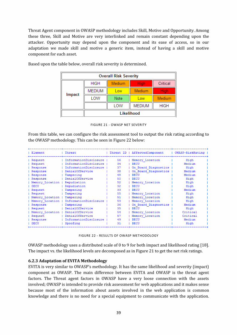
39
Threat Agent component in OWASP methodology includes Skill, Motive and Opportunity. Among
these three, Skill and Motive are very interlinked and remain constant depending upon the
attacker. Opportunity may depend upon the component and its ease of access, so in our
adaptation we made skill and motive a generic item, instead of having a skill and motive
component for each asset.
Based upon the table below, overall risk severity is determined.
FIGURE 21 - OWASP NET SEVERITY
From this table, we can configure the risk assessment tool to output the risk rating according to
the OWASP methodology. This can be seen in Figure 22 below:
FIGURE 22 - RESULTS OF OWASP METHODOLOGY
OWASP methodology uses a distributed scale of 0 to 9 for both impact and likelihood rating [18].
The impact vs. the likelihood levels are decomposed as in Figure 21 to get the net risk ratings.
6.2.3 Adaptation of EVITA Methodology
EVITA is very similar to OWASP’s methodology. It has the same likelihood and severity (impact)
component as OWASP. The main difference between EVITA and OWASP is the threat agent
factors. The Threat agent factors in OWASP have a very loose connection with the assets
involved; OWASP is intended to provide risk assessment for web applications and it makes sense
because most of the information about assets involved in the web application is common
knowledge and there is no need for a special equipment to communicate with the application.
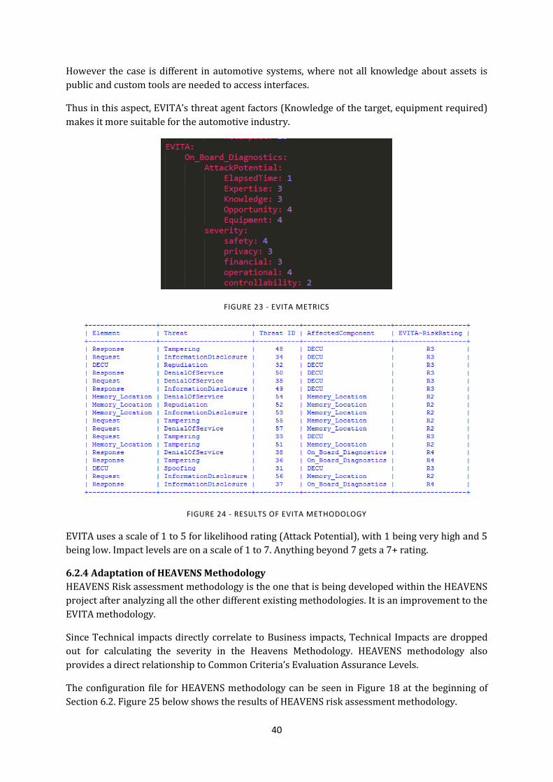
40
However the case is different in automotive systems, where not all knowledge about assets is
public and custom tools are needed to access interfaces.
Thus in this aspect, EVITA’s threat agent factors (Knowledge of the target, equipment required)
makes it more suitable for the automotive industry.
FIGURE 23 - EVITA METRICS
FIGURE 24 - RESULTS OF EVITA METHODOLOGY
EVITA uses a scale of 1 to 5 for likelihood rating (Attack Potential), with 1 being very high and 5
being low. Impact levels are on a scale of 1 to 7. Anything beyond 7 gets a 7+ rating.
6.2.4 Adaptation of HEAVENS Methodology
HEAVENS Risk assessment methodology is the one that is being developed within the HEAVENS
project after analyzing all the other different existing methodologies. It is an improvement to the
EVITA methodology.
Since Technical impacts directly correlate to Business impacts, Technical Impacts are dropped
out for calculating the severity in the Heavens Methodology. HEAVENS methodology also
provides a direct relationship to Common Criteria’s Evaluation Assurance Levels.
The configuration file for HEAVENS methodology can be seen in Figure 18 at the beginning of
Section 6.2. Figure 25 below shows the results of HEAVENS risk assessment methodology.
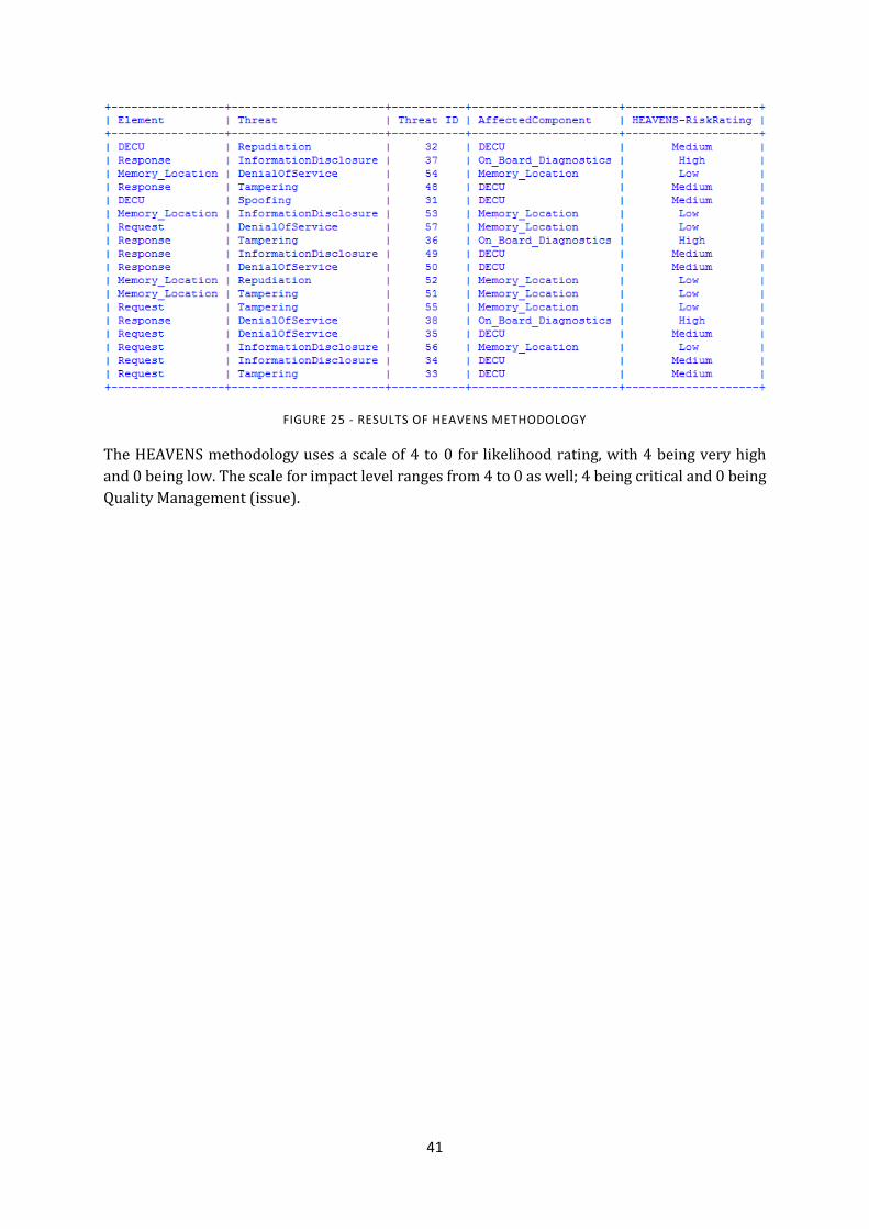
41
FIGURE 25 - RESULTS OF HEAVENS METHODOLOGY
The HEAVENS methodology uses a scale of 4 to 0 for likelihood rating, with 4 being very high
and 0 being low. The scale for impact level ranges from 4 to 0 as well; 4 being critical and 0 being
Quality Management (issue).
42
7
7.Evaluation and Results
The following sections include results and evaluation pertaining to our threat modeling and risk
assessment process.
7.1 Evaluation: Automated vs. Manual – Threat Modeling Microsoft’s SDL threat modeling tool works quite well, but it was important to do our own
evaluation to ensure that all threats were being detected. After creating the flow diagrams for
each use case, we were able to perform our own analysis and determine what threats may be
present. During this analysis, we decided not to view any of the threats from the SDL tool’s
analysis so that we could be thorough and complete.
A number of threats that came up were either directly or indirectly related to all threats within
STRIDE. For example, threats such as spoofing, tampering, and repudiation were not only found
automatically by the tool, but also during our manual discovery. Other threats that were thought
of, such as jamming, interception of information or manipulation of data in transit, could be
categorized as another way of describing threats within the STRIDE model. In this case, jamming
could be mapped to denial of service, interception of information mapped to information
disclosure and manipulation of data mapped to tampering. In the end, we came to the conclusion
that the STRIDE model methodology and the SDL tool worked well enough to cover all threat
detections.
7.2 Evaluation: Automated vs. Manual – Risk Assessment By taking the file generated by the SDL tool, putting it through the XML parser and finally
through our implemented risk assessment tool, we were able to create a results table for all of
the risk assessment methodologies. From this table, we were able to determine which
methodology made the most sense for a vehicular system and the automotive industry. While
the risk assessment tool works in an automated fashion, we made sure to do our own manual
evaluation to make sure that the risk ratings were correct according to the methodologies used.
In this section, we compare the results of the OWASP, EVITA and HEAVENS risk assessment
methodology to determine which one is best for vehicular systems while also ensuring that the
risk rating tool itself rates the risks correctly for each use case. CVSS, while in the table provided,
was not utilized in this evaluation and comparison since the metrics used by CVSS are not
specific enough. This makes CVSS unsuitable for the Automotive Industry and for the
investigated vehicular system.
Figure 26 shows the results of OWASP, EVITA and HEAVENS methodologies once information
from the parser is passed to the risk rating tool.

43
FIGURE 26 - COMPARISON OF VARIOUS RISK ASSESSMENT METHODOLOGIES: ON-BOARD DIAGNOSTICS USE
CASE
The risk ratings within this table were also done by hand in parallel with the risk assessment
tool. By evaluating this manually and comparing it to the tool’s output, we were able to discern
that the tool was able to determine the correct risk ratings as long as the configuration file for
each methodology was correct. From that point on, we were able to use the risk assessment tool
to determine ratings for each use case. From there we were able to evaluate and compare each
risk assessment methodology and determine which would work best for our purposes.
The results of HEAVENS and EVITA are very similar (R4 in EVITA maps to High in HEAVENS, R3
to medium and R2 to low) but differ from OWASP. In this use case, all the attacks pertaining to
Memory_Location differ significantly between OWASP (HIGH or CRITICAL) to EVITA/HEAVENS
(LOW). The reason for this difference is one of the disadvantages of OWASP risk assessment
methodology. OWASP, doesn’t consider that asset specific information may be needed while
determining the Attack Potential/Likelihood. Accessing the Memory_Location might need
special tools and knowledge about the system that might not be public. HEAVENS and EVITA,
however, consider these factors and thus correctly rate the risk as LOW.
Other than this specific threat, there is not a significant difference in risk rating levels among
these three methodologies. The risk rating in this example is highly subjective due to non-public
information about vehicular systems and other intrinsic details about the inner workings of the
system. In order to get a precise rating, it is safe to say that one might need to have very detailed
information about the system and would have use statistical methods to predict the metrics
required for the assessment.

44
8
8.Discussion/Future Work
The entirety of this project has brought up a number of aspects that deal with security and safety
within a vehicular system. A number of current projects continue to provide valuable results
that include software modification, threat detection and risk assessment rating. They have been
the stepping stone for the outcome of what is defined by the whole of this project. From EVITA
to HEAVENS to Microsoft’s Security Development Lifecycle (SDL), we have developed and
evaluated a process that deals with threat modeling and risk assessment to help with
determining correct security requirements for a vehicular system.
The use cases described can be considered very high level, but in our opinion, the threat
modeling tool and risk assessment tool described, can be applied to almost any level of various
functions. This can be useful in most segments of the development process, which in turn can
help solidify the security of one’s vehicular system.
In another sense, this project has helped pioneer a new way of looking at threat modeling within
a vehicular system. It is one of the first times (that we are aware of) that Microsoft’s STRIDE
model and Security Development Lifecycle are being applied to a vehicular system. While it was
modified in some ways to fit our purposes, we find it surprising that there isn’t more exploration
into Microsoft’s already available options in this area. This however, leads us to believe that
future work can be done with these techniques in mind.
The next step of this project would have to relate to the completion of what we call the “black
box.” As mentioned in Section 1.3, the scope of this project encompassed the threat modeling
and risk assessment as separate processes. The point of the “black box” is to create an
automated procedure that pertains to these two processes. This could be a complete tool that
would consist of both processes and automatically produce the correct suggestions for security
requirements and/or mitigations for functionalities that are entered.
While this tool was not produced during the duration of this project, we believe that enough
information, tests and tools have been provided to bring about this type of implementation
within a reasonable amount of time.

45
9
9.Conclusion
As stated in the introduction of this report, safety is the most paramount aspect considered
when developing a vehicular system. With that said, safety is increased with the correct security
requirements put into place. However, in order to determine those security requirements, a
process to determine possible threats and risk of those threats to the system is needed. By
creating full threat models from use case flow diagrams and by assessing the risk of the detected
threats within those models, one is able to determine the best security requirements for a
vehicular system.
We started by reviewing all current work in this field including the current state-of-the-art and
various on-going projects that pertain to the security of vehicular systems. We also familiarized
ourselves with use cases that are currently implemented within a vehicular system. From all this
information, we determined which methods, processes, tools and methodologies were best for
the automotive industry. We took those factors and applied/adapted them to a process that
contains both threat modeling and risk assessment of a vehicular system.
Threat modeling was done with an already known tool provided by Microsoft. After creating our
use case flow diagrams with the SDL tool’s simple drag and drop system, we evaluated the tool
to make sure it covered all feasible threats to the system. From this evaluation, we were able to
determine that the STRIDE threat model and the SDL tool cover all possible threats to a
vehicular system.
Using the files that were created by the SDL tool, we were able to implement a parser and risk
assessment tool. This tool can be used for any risk assessment methodology as long as the
configuration file is correct. We then used the risk assessment tool to determine which risk
assessment methodology can be correctly applied to the automotive industry. In the end, the
HEAVENS and EVITA methodologies were found to be the best risk assessment methodologies to
be used since others, such as OWASP, didn’t consider that asset specific information may be
needed in order to determine the Attack Potential/Likelihood of a specific threat.
In the end, we have come down to the conclusion that while there are a number of different
threat modeling and risk assessment methodologies that can be applied to the standard IT
system, all of the ones evaluated within this project need to be modified in order to be applicable
to the standard vehicular system. This project, however, shows how these modifications are
actually simple adaptations. It also shows the already available tools that can be modified to be
used for the automotive industry. While the project itself can be expanded or further researched
to deal with a more detailed depiction of a standard vehicular system, we believe that we have
created a process that is thorough and complete on all levels; a process that can be utilized to

46
determine the best security requirements and mechanisms to be used in order to secure today’s
vehicular systems.

47
Appendix A: Full SDL Process
Security
Trained?
Complete
Core
Training
Tools
ID’d?
Response
Plan?
Document
emergency
response
procedures
Specify
compilers,
tools, flags
& options
Unsafe
APIs?
Final
Security
Review?
Review all
security &
privacy
activities
Ban bad
functions
& APIs
Static
Analysis?
Release
Archive?
Archive all
pertinent
technical
data
Perform
periodic
static code
analysis
Design
Reqs?
Perform
all
subtasks
Security
Consult
advisors
for review
Privacy
Consult
advisors
for review
Crypto
Consult
advisors
for review
Attack
Surface?
Layered
defenses &
least
privilege
Threat
Models?
Assess
threats
using
STRIDE
Dynamic
Analysis?
Conduct
runtime
verification
tests
Fuzz
Tests?
Fuzz all
program
interfaces
TM/ASR
Review?
Validate
models
against
code
complete
project
Pen Tests?
(Option)
Deliberate
attack
testing on
critical
components
END
Experts
ID’d?
Assign
advisors &
team leads
Min
Reqs?
Define
minimum
security
criteria
Bug
Track?
Specify
bug/work
tracking
tool
Quality
Gates?
Specify
quality
gates &
bug bars
Assessed
Risk?
Use SRA/
PRA to
codify risk
Sec/Priv
Reqs?
Perform all
subtasks
Yes
No
No
No
No
No
No
No
No
No
Yes
No
No
No
No
Yes
Yes
Yes
Yes
Yes
Yes
Yes
YesYes
No
No
No
No
No
No
Yes
Yes
Yes
Yes
Yes
Yes
Yes
Yes
Yes
Yes
No
No
No
Yes
Yes
Training Requirements Design Implementation Verification Release Response
No
Appendix B: Final Use Case Diagrams for Creating Threat Models (All)

48
Wired Diagnostics Model
Remote Diagnostics
On-Board Diagnostics (OBD)
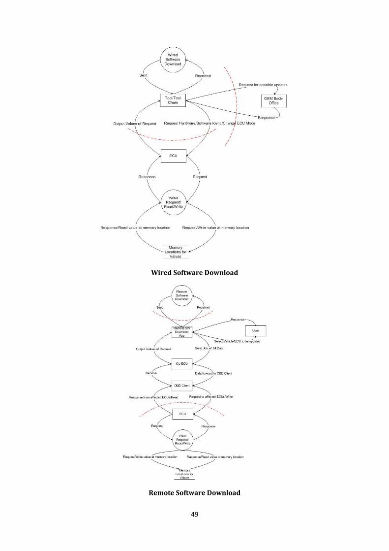
49
Wired Software Download
Remote Software Download
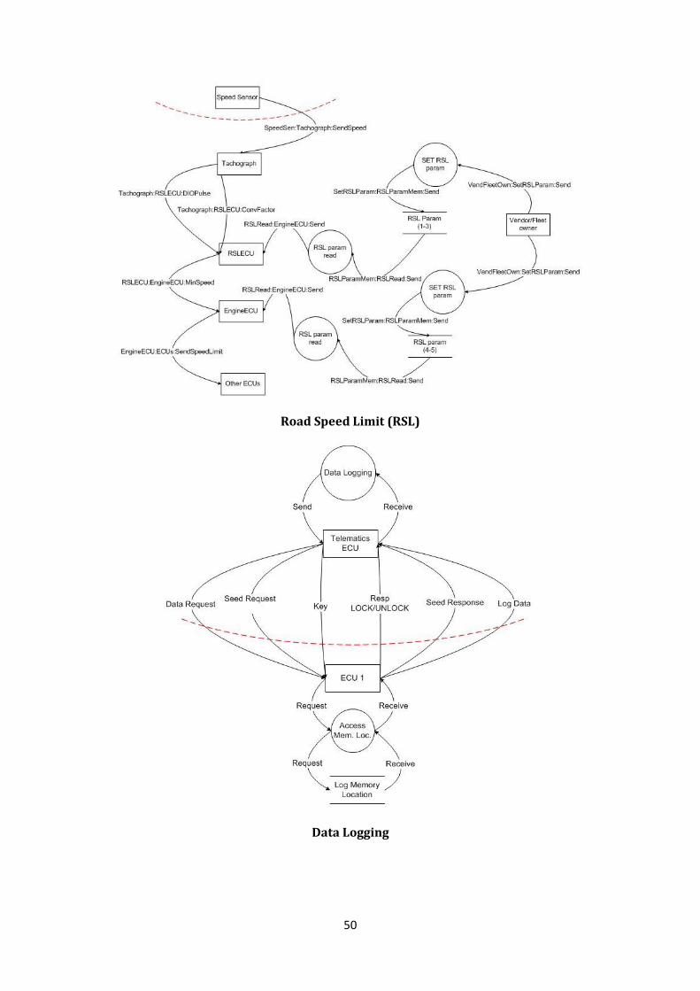
50
Road Speed Limit (RSL)
Data Logging
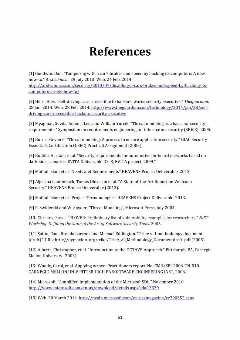
51
References
[1] Goodwin, Dan. “Tampering with a car’s brakes and speed by hacking its computers: A new
how-to.” Arstechnica. 29 July 2013. Web. 24 Feb. 2014
http://arstechnica.com/security/2013/07/disabling-a-cars-brakes-and-speed-by-hacking-its-
computers-a-new-how-to/
[2] Hern, Alex. “Self-driving cars irresistible to hackers, warns security executive.” Theguardian.
28 Jan. 2014. Web. 28 Feb. 2014. http://www.theguardian.com/technology/2014/jan/28/self-
driving-cars-irresistible-hackers-security-executive
[3] Myagmar, Suvda, Adam J. Lee, and William Yurcik. "Threat modeling as a basis for security
requirements." Symposium on requirements engineering for information security (SREIS). 2005.
[4] Burns, Steven F. "Threat modeling: A process to ensure application security." GIAC Security
Essentials Certification (GSEC) Practical Assignment (2005).
[5] Ruddle, Alastair, et al. "Security requirements for automotive on-board networks based on
dark-side scenarios. EVITA Deliverable D2. 3, EVITA project, 2009."
[6] Mafijul Islam et al "Needs and Requirements" HEAVENS Project Deliverable. 2013.
[7] Aljoscha Lautenbach, Tomas Olovsson et al. "A State-of-the-Art Report on Vehicular
Security." HEAVENS Project Deliverable (2013).
[8] Mafijul Islam et al "Project Termonologies" HEAVENS Project Deliverable. 2013.
[9] F. Swiderski and W. Snyder, “Threat Modeling”, Microsoft Press, July 2004
[10] Christey, Steve. "PLOVER: Preliminary list of vulnerability examples for researchers." NIST
Workshop Defining the State of the Art of Software Security Tools. 2005.
[11] Saitta, Paul, Brenda Larcom, and Michael Eddington. "Trike v. 1 methodology document
[draft]." URL: http://dymaxion. org/trike/Trike_v1_Methodology_Documentdraft. pdf (2005).
[12] Alberts, Christopher, et al. "Introduction to the OCTAVE Approach." Pittsburgh, PA, Carnegie
Mellon University (2003).
[13] Woody, Carol, et al. Applying octave: Practitioners report. No. CMU/SEI-2006-TN-010.
CARNEGIE-MELLON UNIV PITTSBURGH PA SOFTWARE ENGINEERING INST, 2006.
[14] Microsoft. “Simplified Implementation of the Microsoft SDL.” November 2010.
http://www.microsoft.com/en-us/download/details.aspx?id=12379
[15] Web. 20 March 2014. http://msdn.microsoft.com/en-us/magazine/cc700352.aspx

52
[16] Scarfone, Karen, and Peter Mell. "An analysis of CVSS version 2 vulnerability scoring."
Proceedings of the 2009 3rd International Symposium on Empirical Software Engineering and
Measurement. IEEE Computer Society, 2009.
[17] Mell, Peter, Karen Ann Kent, and Sasha Romanosky. The common vulnerability scoring
system (CVSS) and its applicability to federal agency systems. US Department of Commerce,
National Institute of Standards and Technology, 2007.
[18] Mell, Peter, Karen Scarfone, and Sasha Romanosky. "A complete guide to the common
vulnerability scoring system version 2.0." Published by FIRST-Forum of Incident Response and
Security Teams. 2007.
[19] Web. 15 May 2014 https://www.owasp.org/index.php/OWASP_Risk_Rating_Methodology
[20] Web. 24 May 2014. http://www.simmasoftware.com/j1939.html
[21] Web. 12 April 2014. http://www.bosch-
semiconductors.de/en/ubk_semiconductors/safe/ip_modules/what_is_can/what_is_can.html
[22] Gühmann, Clemens. "Model-based testing of automotive electronic control units." Test 2005
Conference, May. 2005.
[23] Schmerler, Stefan, et al. "AUTOSAR–Shaping the Future of a Global Standard." 5th VDI
Congress Baden-Baden Spezial. 2012.
[24] Fürst, Simon, et al. "AUTOSAR–A Worldwide Standard is on the Road." 14th International
VDI Congress Electronic Systems for Vehicles, Baden-Baden. 2009.
[25] Kirschke-Biller, Frank. "AUTOSAR-A worldwide standard Current developments, roll-out
and outlook." 15th International VDI Congress Electronic Systems for Vehicles, Baden-Baden,
Germany. 2011.
[26] Common Criteria for Information Technology Security Evaluation, Version 3.1, Revision 4,
CCMB-2012-09-001, Common Criteria.
[27] "Road vehicles – Unified diagnostic services (UDS) – Part 1: Specification and requirements
(ISO 14229-1:2013, IDT)", Internation Standardization Organization, April, 2013.
[28] Shostack, Adam. "Experiences threat modeling at microsoft." Modeling Security Workshop.
Dept. of Computing, Lancaster University, UK. 2008.
[29] Schmidt, Karsten, et al. Adapted Development Process for Security in Networked
Automotive Systems. No. 2014-01-0334. SAE Technical Paper, 2014.