Embed Size (px)
Citation preview

PT® THREADING MACHINE
FOR PRODUCT OR WARRANTY INFORMATION CONTACT ARGCO - PIPINGTOOLS DIVISION
PHONE: 800-854-1015 • FAX: 760-727-327051816 DRYDEN PLACE #101 • CARLSBAD CA 92008
www.pipingtools.com
PT® Reversible 1/2 HP universal motor. Capacity: 1/8"-2" (3mm-50mm) pipeOn/Off/Reverse switch.
Specifications PT®Motor: 1/2 HP, universal, reversible motor, single-phase, 25-60 Hz, 115V Switch: FOR/OFF/REV and Integral Foot Switch Chuck: Speed chuck with replaceable jaws Spindle Speed: 38 RPM Support Bars: Heavy-duty
Complete PT® Threading Machine Consists of: •PT® Power Drive only with foot switch •Stand •Carriage with lever •Reamer •Cutter •Universal die head •Set 1/2" - 3/4" Universal HSS dies •Set 1" - 2" Universal HSS dies •Oiler •1 gallon Tuf-Cut® thread cutting oil
WARNING!Read this Operator’s Manual carefully before using this tool.
Failure to understand and follow the contents of this manual may result in electricalshock, fire and/or serious personal injury.

www.pipingtools.com
General Safety InformationWARNING! Read and understand all instructions. Failure to follow all instructions listed below mayresult in electric shock, fire, and/or seriouspersonal injury.
Work Area Safety• Keep your work area clean and well lit. Cluttered benches and dark areas invite accidents.
• Do not operate power tools in explosive atmospheres, such as in the presence of flammable liquids, gases, or dust. Tools create sparks which may ignite the dust or fumes.
• Keep bystanders, children, and visitors away while operating tool. Distractions can cause you to lose control.
• Keep floors dry and free of slippery materials such as oil.
• Guard or the area when work piece extends beyond machine. A guard or barricade that provides a minimum of three feet clearance around the work piece will reduce the risk of entanglement.
Electrical Safety• Grounded tools must be plugged into an outlet, properly installed and grounded in accordance with all codes and ordinances. Never remove the grounding prong or modify the plug in any way. Do not use any adapter plugs. Check with a qualified electrician if you are in doubt as to whether the outlet is properly grounded. If the tool should electrically malfunction or break down, grounding provides a low resistance path to carry electricity away from the user.
• Avoid body contact with grounded surfaces. There is an increased risk of electrical shock if your body is grounded.
• Don’t expose electrical tools to rain or wet conditions. Water entering a tool will increase the risk of electrical shock.
• Do not abuse cord. Never use the cord to carry the tools or pull the plug from an outlet. Keep cord away from heat, oil, sharp edges or moving parts. Replace damaged cords immediately. Damaged cords increase the risk of electrical shock.
• When operating a power tool outside, use an outdoor extension cord marked “W-A” or “W”. These cords are rated for outdoor use and reduce the risk of electrical shock.• Use only three-wire extension cords which have three-prong grounding plugs and three-pole receptacles which accept the tool’s plug. Use of other extension cords will not ground the tool and increase the risk of electrical shock.• Use proper extension cords. (See chart.) Insufficient conductor size will cause excessive voltage drop and loss of power.
• Keep all electric connections dry and off the ground. Do not touch plugs or tool with wet hands. Reduces the risk of electrical shock.
Personal Safety• Stay alert, watch what you are doing and use common sense when operating a power tool. Do not use tool while tired or under the influence of drugs, alcohol, or medications. A moment of inattention while operating power tools may result in serious personal injury.
• Dress properly. Do not wear loose clothing or jewelry. Contain long hair. Keep your hair, clothing, and gloves away from moving parts. Loose clothes, jewelry, or long hair can be caught in moving parts.
• Avoid accidental starting. Be sure switch is OFF before plugging in. Carrying tools with your finger on the switch or plugging in tools that have the switch ON invites accidents.
• Remove adjusting keys before turning the tool ON. A wrench or a key that is left attached to a rotating part of the tool may result in personal injury.
• Do not overreach. Keep proper footing and balance at all times. Proper footing and balance enables better control of the tool in unexpected situations.
• Use safety equipment. Always wear eye protection. Dust mask, non-skid safety shoes, hard hat, or hearing protection must be used for appropriate conditions.
PT® THREADING MACHINE
1
www.pipingtools.com
Tool Use and Care• Do not use tool if switch does not turn it ON orOFF. Any tool that cannot be controlled with the switchis dangerous and must be repaired.
• Disconnect the plug from the power source beforemaking any adjustments, changing accessories,or storing the tool. Such preventive safety measuresreduce the risk of starting the tool accidentally.
• Store idle tools out of the reach of children andother untrained persons. Tools are dangerous inthe hands of untrained users.
• Check for misalignment or binding of movingparts, breakage of parts, and any other conditionthat may affect the tool's operation. If damaged,have the tool serviced before using. Many accidentsare caused by poorly maintained tools.
• Use only accessories that are recommended foryour tool. Accessories that may be suitable for one toolmay become hazardous when used on another tool.
• Keep handles dry and clean; free from oil andgrease. Allows for better control of the tool.Service
• Tool service must be performed only by qualifiedrepair personnel. Service or maintenance performedby unqualified repair personnel could result in injury.
• When servicing a tool, use only identical replacementparts. Follow instructions in the MaintenanceSection of this manual. Use of unauthorized parts orfailure to follow maintenance instructions may create arisk of electrical shock or injury.
Foot Switch SafetyUsing a power drive or threading machine without afoot switch increases the risk of serious injury. Afoot switch provides better control by letting youshut off the motor by removing your foot. If clothingshould become caught in the machine, it will continueto wind up, pulling you into the machine. Becausethe machine has high torque, the clothing itself canbind around your arm or other body parts withenough force to crush or break bones.
Machine Safety• Power Drive is made to thread and cut pipe orbolt and to power RIDGID roll grooving equipment.Follow instructions on proper use of thismachine. Do not use for other purposes suchas drilling holes or turning winches. Other uses ormodifying this power drive for other applications mayincrease the risk of serious injury.
• Secure machine to bench or stand. Support longheavy pipe with pipe supports. This practice willprevent tipping.
• Do not wear gloves or loose clothing when operatingmachine. Keep sleeves and jackets buttoned.Do not reach across the machine or pipe. Clothingcan be caught by the pipe or machine resulting inentanglement and serious injury.
• Operate machine from side with REV/OFF/FORswitch. Eliminates need to reach over the machine.
• Do not use this machine if the foot switch is brokenor missing. Foot switch is a safety device toprevent serious injury.
PT® THREADING MACHINE
2

www.pipingtools.com
Machine Safety (continued)• Keep hands away from rotating pipe and fittings.Stop the machine before wiping pipe threads orscrewing on fittings. Allow the machine to come toa complete stop before touching the pipe ormachine chucks. This practice will prevent entanglementand serious injury.
• Do not use this machine to make or break fittings.This practice is not an intended use of the machine andcan result in serious injury.
• Tighten chuck handwheel and engage rear centeringdevice on the pipe before turning on themachine. Prevents oscillation of the pipe.
• Keep covers in place. Do not operate the machinewith covers removed. Exposure to moving parts mayresult in entanglement and serious injury.
• Lock foot switch when machine is not in use This will avoid accidental starting.
Description, Specifications andStandard EquipmentDescriptionThe PT® Power Drive is an electric motor-driven machine which centers and chucks pipe, conduit and rod and rotates it while threading, cutting and reaming operations are performed.Forward (clockwise) or Reverse (counterclockwise)rotation can be selected with the FOR/OFF/REV switchand a foot switch provides ON/OFF control of the motor.
The threading, cutting and reaming operations can beperformed by conventional hand tools or tools designed formounting on the Power Drive. A manual oiling system isavailable to flood the workpiece with thread cutting oil during the threading operation. Geared Threaders can also beused with the Power Drive to thread larger diameter pipe.
PT® THREADING MACHINE
3
The PT® Power Drive can also be used as a power source for roll grooving equipment. Designed to attach to the sup-port arms of the Power Drive, the roll grooving equipment forms standard roll grooves on a variety of pipe sizes and materials.Contact an ARGCO-PT distributor or consult theARGCO catalog for specifications on roll groovingequipment.
SpecificationsThreading Capacity .......Pipe 1/8” through 2” Bolt 1/4” through 2” Geared Threaders: Pipe 2-1/2” through 6”Chuck ............................Speed Grip Chuck with Replaceable Jaw InsertsRear Centering Device....Cam Action Rotates with ChuckOperating Speed ............38 RPM or 57 RPMMotor:Type................................UniversalHorsepower.....................1/2 HP

www.pipingtools.com
Machine AssemblyWARNINGTo prevent serious injury, proper assembly of thePower Drive is required. Failure to mount thePower Drive to a stable stand or bench may resultin tipping and serious injury. The following proceduresshould be followed:Mounting on Stand1. Set up the Stand by opening legs and pushingdown on the tray. Legs should be stiff and the standshould not wobble.
NOTE! The tristand leg stiffness can be increased ordecreased by the following procedure:• Place stand upside down on a flat surface.• Unlock tray so legs are loose.• Locate the set screw on the tray leg support on therear leg (Figure 3).• Loosen the set screw to make the adjustment. Toincrease stiffness, move the tray leg support uptowards the base. To decrease stiffness, movethe tray leg down towards the feet.• Tighten the set screw (increasing leg stiffnessincreases tray tension).
2. Mount power drive on the stand using bolts and wingnuts (Figure 3).
PT® THREADING MACHINE
4
Mounting Carriage Assembly1. Inspect the support bars to insure they are forwardand secured by two (2) retaining ring assemblies.Retaining ring set screws must be tight (Figure 4).2. Secure eyebolt to the 311A Carriage. Slide leverarm through the eyebolt assembly and secure tocollar assembly with shoulder bolt (Figure 4).3. Tighten collar assembly thumb screw into grooveon support bar.4. Install the 360 Cutter and 341 Reamer by insertingarm in the slot provided in the carriage and securewith the drive pin (Figure 4).5. Install 811A Die Head by inserting die head postinto the mating hole in the carriage.NOTE! When fully inserted, spring-loaded ball will holddie head in place.

www.pipingtools.com
Machine InspectionWARNINGTo prevent serious injury, inspect your Power Drive. The following inspection procedures should be performed on a daily basis:
1. Make sure Power Drive is unplugged and the directionalswitch is set to the OFF position (Figure 3).
2. Clean the speed chuck jaws with a wire brush.
3. Inspect the jaw inserts for excessive wear. Refer to theMaintenance Instructions if they need to be replaced.NOTE! For plastic and coated work pieces, special jawinserts should be used to prevent damaging the workpiece.
4. Make sure the foot switch is present and attached tothe Power Drive (Figure 3).Do not operate the Power Drive without afoot switch.
5. Inspect the power cord and plug for damage. If theplug has been modified, is missing the groundingpin or if the cord is damaged, do not use the PowerDrive until the cord has been replaced.
6. Inspect the Power Drive for any broken, missing,misaligned or binding parts as well as any other conditionswhich may affect the safe and normal operationof the machine. If any of these conditions are present,do not use the Power Drive until any problemhas been repaired.
7. Lubricate the Power Drive spindle bearings if necessaryaccording to the Maintenance Instructions.
8. Use tools and accessories that are specificallydesigned for your Power Drive and meet the needs ofyour application. The correct tools and accessoriesallow you to do the job successfully and safely.Accessories suitable for use with other equipmentmay be hazardous when used with this Power Drive.control slipping from your grip.
PT® THREADING MACHINE
5
9. Clean any oil, grease or dirt from all handles andcontrols. This reduces the risk of injury due to a tool orInspect the cutting edges of your tools and dies. Ifnecessary, have them replaced prior to using thePower Drive. Dull or damaged cutting tools anddies can lead to binding, tool breakage and poorquality threads.10. Clean metal shavings and other debris from the chiptray of the Oiler. Check the level and quality of thethread cutting oil. Replace or add oil if necessary.
NOTE! Thread cutting oil lubricates and cools the threadsduring the threading operation. A dirty or poorgrade cutting oil can result in poor thread quality.
Machine and Work Area Set-Up
To prevent serious injury, proper set-up of themachine and work area is required. The followingprocedures should be followed to set-up the machine:1. Locate a work area that has the following: • Adequate lighting. • No flammable liquids, vapors or dust that may ignite. • Grounded electrical outlet. • Clear path to the electrical outlet that does not contain any sources of heat or oil, sharp edges or moving parts that may damage electrical cord. • Dry place for machine and operator. Do not use the machine while standing in water. • Level ground.
2. Clean up the work area prior to setting up any equip-ment. Always wipe up any oil that may have splashedor dripped from the machine or oiler to prevent slipsand falls.
3. Set up the Power Drive on a flat, level surface.• For a Power Drive mounted on a Stand, open legs of stand and push down on the tray. Legs should be stiff and stand should not wobble.NOTE! To increase or decrease leg stiffness, refer toinstructions on “Mounting On Stand”.

www.pipingtools.com
PT® THREADING MACHINE
6
Machine and Work Area Set-Up
4. If the workpiece extends more than four (4) feetbeyond the Power Drive, use one or more pipe standsto prevent tipping and the oscillation of the pipe.
5. If the workpiece extends beyond the Power Drive, setupguards or barricades to create a minimum ofthree (3) feet of clearance around the Power Driveand workpiece. This “safety zone” prevents othersfrom accidentally contacting the machine or workpieceand either causing the equipment to tip or becomingentangled in the rotating parts.
6. If necessary, fill the Oiler with Tuf-Cut ThreadCutting Oil. Position the oiler under the front of thePower Drive (Figure 3).
7. Make sure FOR/OFF/REV switch is in the OFF position.
8. Position the foot switch so that the operator cansafely control the machine, tools and workpiece. Asshown in Figure 8, it should allow the operator todo the following:• Stand facing the directional switch.• Use the foot switch with his left foot.• Have convenient access to the directional switch,tools and chucks without reaching across themachine.Machine is designed for one person operation.
9. Plug the Power Drive into the electrical outlet makingsure to position the power cord along the clear pathselected earlier. If the power cord does not reachthe outlet, use an extension cord in good condition.
WARNINGTo avoid electrical shock and electrical fires, never usean extension cord that is damaged or does not meet thefollowing requirements:• The cord has a three-prong plug similar to shown in Electrical Safety section.• The cord is rated as “W” or “W-A” if being used outdoors.• The cord has sufficient wire thickness (14 AWG below 25'/12 AWG 25' - 50'). If the wire thickness is too small, the cord may overheat, melting the cord’s insulation or causing nearby objects to ignite.To reduce risk of electrical shock, keep all electrical con-nections dry and off the ground. Do not touch plug with wet hands.10. Check the Power Drive to insure it is operating prop-erly.• Flip the directional switch to FOR (Forward). Press and release the foot switch. Check that the Power Drive rotates in a counterclockwise direction as you are facing the front chuck. Have the Power Drive serviced if it rotates in the wrong direction or if the foot switch does not control its stopping or starting.• Depress and hold the foot switch. Inspect the moving parts for misalignment, binding, odd noises or any other unusual conditions that may affect the safe and normal operation of the machine. If such conditions are present, have the power drive serviced.• Flip the directional switch to REV (Reverse). Press and release the foot switch. Check that the Power Drive rotates in a clockwise direction as you are facing the chuck.• Release the foot switch and flip the directional switch to OFF.

www.pipingtools.com
PT® THREADING MACHINE
7
Operating InstructionsFor Using Hand ToolsDo not wear gloves or loose clothing when operating Power Drive. Keep sleeves and jackets buttoned. Do not reach across the machine or pipe. Do not use this Power Drive if the foot switch is broken or missing. Always wear eye protection to protect eyes from dirt and other foreign objects.Keep hands away from rotating pipe and fittings.Stop the machine before wiping pipe threads or screwing on fittings. Allow the machine to come to a complete stop before touching the pipe or machine chucks.Do not use this machine to “make-on” or “break off” fittings. This prac-tice is not an intended use of this Power Drive.
Installing Pipe In Power Drive:1. Mark the pipe at the desired length if it is being cut to length.2. Insert the pipe into the Power Drive so that the end to be worked or the cutting mark is located about 12” to the front of the speed chuck jaws.3. Insert workpieces less than 2 feet long from the front of the machine. Insert longer pipes through either end so that the longer section extends out beyond the rear of the Power Drive. To avoid equipment tip-overs, position the pipe supports under the workpiece.4. Tighten the rear centering device around the pipe by using a counterclockwise rotation of the handwheel at the rear of the Power Drive. This prevents movement of the pipe that can result in poor thread quality.5. Secure the pipe by using repeated and forceful counterclockwise spins of the speed chuck handwheel at the front of the Power Drive. This action “hammers” the jaws tightly around the pipe.6. Extend both support bars fully beyond the front of the Power Drive.
Cutting Pipe with Hand Cutter1. Position the pipe cutter on the workpiece with the cutter wheels facing up (see “Accessories” section for pipe cutters recommended for use with this Power Drive).
2. Align the cutter wheels with the mark on the pipe and rest the pipe cutter’s body on the left support bar (Figure 5). Hand-tighten the pipe cutter to the workpiece using the feedscrew handle while keeping the cutter wheels aligned with the mark.
3. Assume the correct operating posture (Figure 8). This will allow you to maintain proper balance and to safely keep control of the machine and tools. • Be sure you can quickly remove your foot from the foot switch. • Stand facing the directional switch. • Be sure you have convenient access to directional switch, tools and chucks. • Do not reach across the machine or workpiece.
4. Flip the directional switch to FOR (Forward).
5. Grasp the pipe cutter’s feedscrew handle with both hands (Figure 5) and depress and hold down the foot switch with the left foot.
6. Tighten the feedscrew handle slowly and continuously until the pipe is cut. Do not force the cutter into the workpiece.
WARNING: To avoid impact injuries, keep a firm grip on the pipe cutter and be sure it is resting on the support bar. If not held firmly or supported, the tool may rotate or fall to the ground.
7. Release the foot switch and remove your foot from the housing.
www.pipingtools.com
PT® THREADING MACHINE
8
Reaming Pipe with Hand ReamerWARNING: To prevent serious injury, do not use selffeedingspiral reamers with the 300 Power Drive.
1. Flip the directional switch to FOR (Forward).
2. Place the reamer in the end of the pipe (see the “Accessories” section for reamers recommended for use with this Power Drive).
3. Assume the correct operating posture.
4. Rest handle on the left support bar (Figure 6) and hold the reamer handgrip with the right hand. To avoid pinch point injuries, keep your fingers from coming between the reamer and the support bar.
5. Firmly grasp the end of the reamer handle with the left hand, then depress and hold the foot switch down.
6. Push the reamer firmly into the pipe with your right hand until ream is complete. Keep your hand and arm away from any rotating parts and use a firm grip on the handgrip.
7. Release the foot switch and remove your foot from the housing while holding the reamer with both hands.
8. Remove the reamer from the workpiece once the Power Drive has stopped rotating.
Threading Pipe with Hand Threader1. Place the die head of the hand threader on the end of the pipe (see “Accessories” section for hand threaders recommended for use with this Power Drive).
2. Position the ratchet knob on the hand threader so that the arrow on the knob points up.
3. Rest the hand threader ratchet handle on the left support bar (as viewed when facing the front of the Power Drive – Figure 7).
WARNING: To avoid pinch point injuries, keep your fingers from coming between the hand threader and the support bar.
4. Apply Tuf-Cut Thread Cutting Oil to the end of the pipe.
5. Assume the correct operating posture. Check to ensure directional switch is in the FOR (Forward) position.
6. Hold the die head against the workpiece with the right hand.
WARNING: To avoid injury from rotating parts or sharpsurfaces, keep hands and fingers away from anythingother than the outer body of the die head.
7. Depress and hold down the foot switch.
8. Push the die head against the pipe using the palm of the right hand until the dies engage the workpiece. Once engaged, the threads will be cut as the dies pull themselves onto the end of the pipe (Figure 7).
9. Remove the right hand from the area of the die head and liberally oil the dies while the pipe is threaded(Figure 8).
WARNING: To avoid serious injury from rotating parts, allow ade-quate clearance between your hand and the rotating parts while oiling.
10. Release the foot switch and remove your foot from the housing when the pipe reaches the end of the dies.
11. Lift the threader handle slightly with the right hand while sliding the left support bar all the way toward the rear of the drive.

www.pipingtools.com
PT® THREADING MACHINE
9
12. Reverse the ratchet knob. The arrow on the knob should point down.
13. Lower the threader handle below the height of the left support bar.
14. Slide the left support bar back to its fully extended position in front of the Power Drive.
15. Lift and hold the threader handle against the left support bar.
16. Flip the directional switch to REV (Reverse). Depress and hold the foot switch down until the threader has unscrewed itself from the workpiece.
To avoid injury due to falling parts, maintain a firm grip on the threader as the threader will drop to the floor if not supported when unthreaded com-pletely.
17. Release the foot switch and remove your foot from the housing.18. Set the threader down and, if necessary, wipe oil and debris off the threads with a rag, taking care not to cut your hand or fingers on any sharp debris or edges.
19. Check the thread for length and depth (Figure 14).
Removing Pipe from the Power Drive1. Flip the directional switch to OFF.
2. Use repeated and forceful clockwise spins of the speed chuck handwheel at the front of the Power Drive to release the workpiece from the speed chuck jaws.
3. If necessary, loosen the rear centering device using a clockwise rotation of the handwheel at the rear of the Power Drive.
4. Slide the workpiece out of the Power Drive, keeping a firm grip on the workpiece as it clears the Power Drive.
To avoid injury from falling parts or equipment tip-overs when han-dling long workpieces, make sure that the end farthest from the Power Drive is supported prior to removal.
5. Clean up any oil spills or splatter on the ground surrounding the Power Drive.
PT® THREADING MACHINE REPLACEMENT PARTS
1
23
4
5
67
8
9 2
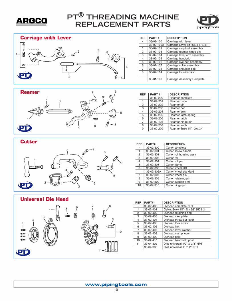
REF-123456789
DESCRIPTIONReamer completeReamer coneReamer pinReamer barReamer armReamer latch springReamer latchReamer hinge pinReamer knobReamer Screw 1/4” - 20 x 3/4”
PART #33-02-20033-02-20133-02-20233-02-20333-02-20433-02-20533-02-20633-02-10333-02-20833-02-209
REF-123456
789
10
PART#33-02-30033-02-30133-02-30233-02-30333-02-30433-02-30533-02-30633-02-306A33-02-30733-02-30833-02-30933-02-310
REF-123456789
1011
DESCRIPTIONDiehead complete NPTDiehead Screw 1/4” - 20 x 5/8” SHCS (2)Diehead retaining ringDiehead cam plateDiehead throw out leverDiehead lock screwDiehead linkDiehead lever washerDiehead clamp leverDiehead postDiehead head with postDies universal 1/2” & 3/4” NPTDies universal 1” to 2” NPT
PART#33-02-40033-02-40133-02-40233-02-40333-02-40433-02-40533-02-40633-02-40733-02-40833-02-40933-02-41033-04-30233-04-303
DESCRIPTIONCutter completeCutter screw handleCutter roll housing assyCutter rollCutter roll pinCutter frameCutter wheel HDCutter wheel standardCutter wheel pinCutter retaining pinCutter support armCutter hinge pin
Cutter
Reamer
www.pipingtools.com10
Universal Die Head
REF--12345678
DESCRIPTIONCarriage with leverCarriage Lever kit (incl. 3, 5, 6, 8)Carriage stop bolt assemblyCarriage reamer hinge pinCarriage lever arm assemblyCarriage handgripCarriage eye bolt assemblyCarriage collar assemblyCarriage shoulder boltCarriage thumbscrew
Carriage Assembly Complete
PART #33-02-10033-02-100A33-02-10133-02-10333-02-10433-02-10533-02-10633-02-10733-02-10833-02-114
33-01-100
Carriage with Lever
12
3
4
5
6
7
8
1
23
4
5
6
78
9
10
12
3
4 56 7 8
9
10
11
PT® THREADING MACHINE REPLACEMENT PARTS
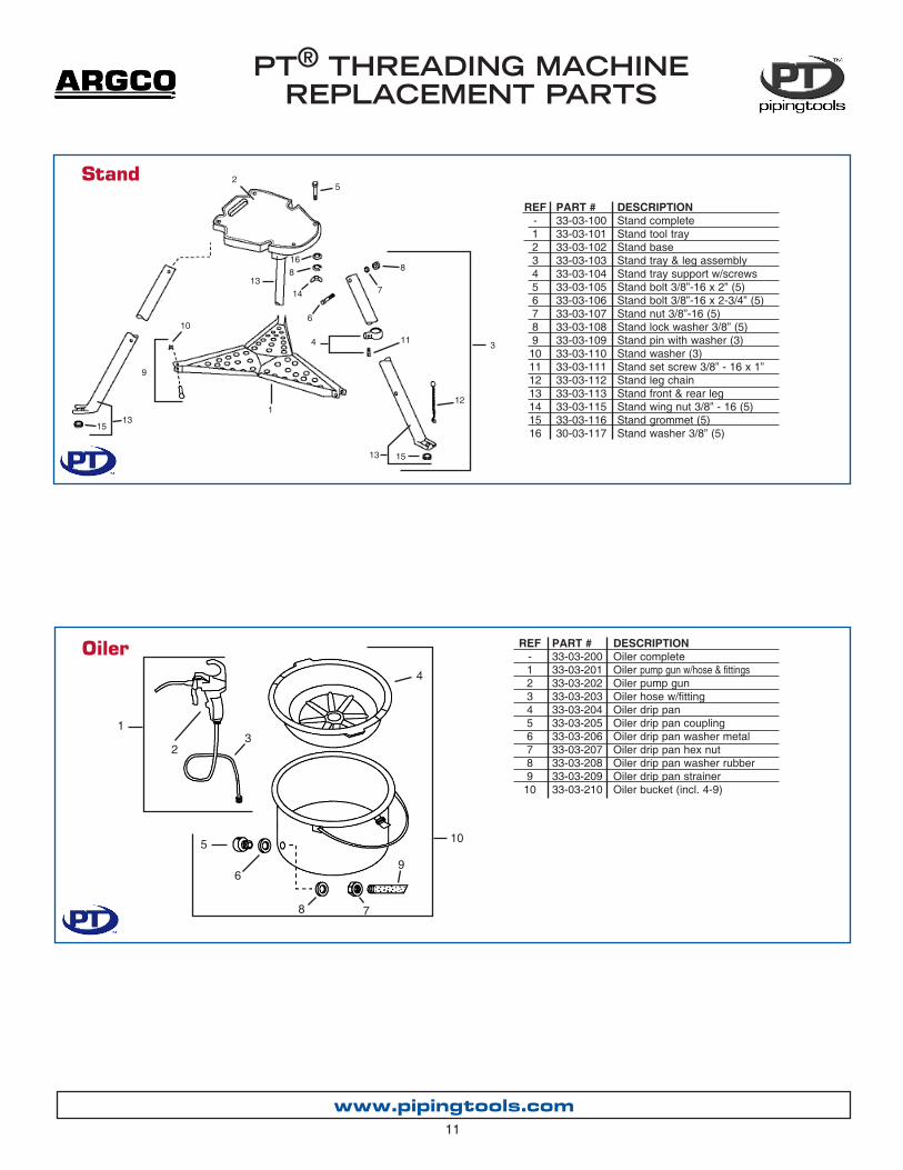
REF-123456789
10
Stand
www.pipingtools.com
PART #33-03-20033-03-20133-03-20233-03-20333-03-20433-03-20533-03-20633-03-20733-03-20833-03-20933-03-210
DESCRIPTIONOiler completeOiler pump gun w/hose & fittingsOiler pump gunOiler hose w/fittingOiler drip panOiler drip pan couplingOiler drip pan washer metalOiler drip pan hex nutOiler drip pan washer rubberOiler drip pan strainerOiler bucket (incl. 4-9)
11
REF-123456789
10111213141516
DESCRIPTIONStand completeStand tool trayStand baseStand tray & leg assemblyStand tray support w/screwsStand bolt 3/8”-16 x 2” (5)Stand bolt 3/8”-16 x 2-3/4” (5)Stand nut 3/8”-16 (5)Stand lock washer 3/8” (5)Stand pin with washer (3)Stand washer (3)Stand set screw 3/8” - 16 x 1”Stand leg chain Stand front & rear leg Stand wing nut 3/8” - 16 (5)Stand grommet (5)Stand washer 3/8” (5)
PART #33-03-10033-03-10133-03-10233-03-10333-03-10433-03-10533-03-10633-03-10733-03-10833-03-10933-03-11033-03-11133-03-11233-03-11333-03-11533-03-11630-03-117
Oiler
1
23
4
5
6
78
9
10
1
2
34 11
12
13
15
10
14
168
5
6
8
7
13
15
13
9

PT® THREADING MACHINE REPLACEMENT PARTS
www.pipingtools.com12
THREADING MACHINE REPLACEMENT PARTS
DESCRIPTIONEC power cord with plug (115V)EC power cord grommetEC switchEC foot switch (remote)EC foot switch (hardwired)
EC micro switch for foot switchEC line cord for foot switch
PART #33-03-30533-03-30733-03-31133-03-31233-03-314
33-03-32033-03-321
Electrical Components REF12345
67
1
2
3
4
5
6
7
Wiring Diagram

PT® THREADING MACHINE REPLACEMENT PARTS
www.pipingtools.com13
DESCRIPTIONPT Motor 115VHousing AssemblyBrush Cap SetBrush Holder SetSet Screw (2)Brush Assembly SetFan Housing AssemblyDowel PinGear Bearings (5)Front Bearing
Motor Components
REF10111213141516171819
DESCRIPTIONDrive Gear1st Gear Assembly2nd Gear AssemblyGear HousingScrew (4)Lock WasherArmature Bearing (2)Armature (115V)Mounting Screw (2)Field (115V)
REF2021222324252628
DESCRIPTION20Locking ScrewLoading SpringWhite Upper LeadRed Lower leadConnector 90 DegreeInsulator (2)Flexible ConduitPlug (Included in Switch Box Assy)

www.pipingtools.com14
Power DriveMain Components
REF123456789
1011
121314151617181920212223242526
DESCRIPTIONScrew, 12 - 24 x 3/4. (6)Lock Washer (6)Centering HeadRear Jaw (3)Step Pin (3)ScrollBack PlateRear Centering AssemblyDrive ShaftRear Bearing-BronzeBody Assembly (Incl. Ref. No. 10, 11, 12, 13,14, 15, 17, 18, 38, 39, 40)Grease FittingSet Screw 5/16. - 24 x 1/4. (2)Pop Rivet (10)Warning PlateThrust RingFront Bearing-BronzeSplit Roll PinDrive Ring, Type IIScrew 5/16. - 18 x 13/4.Set Screw 5/16. - 24 x 1/4. (2)Set Screw 5/16. - 24 x 1/2. (3)Drive Pin, Type II (3)Ring Gear, Type IIHand WheelScroll
REF2728293031323334353637383940414246474849
DESCRIPTIONJaw Insert SetChuck Jaw SetScrew 5/16. - 18 x 23/4. (6)CapSnap Ring (2)Set Screw 1/4. - 18 x 1/4. (2)Ring Assembly (2)Support Bar (Incl. Ref. No. 37)FOR/OFF/REV LabelScrew #8 - 32 x 5/8. (2)Spring Ring (2)Cord GrommetScrew 1/4. - 20 x 5/8. (2)Strain Relief PlateMotor 115V (300)Screw 3/8. - 16 x 11/4. (2)Drive Spring (3)Drive Wedge KitPressure Spring (3)Plunger Kit
PT® THREADING MACHINE REPLACEMENT PARTS

Tric TrayHeavy duty tray with V notch for pipe.Easily attaches to threading machine. No removeable parts to break or lose.
•Keep threading oil & chips in the oiler and off the walls and floor.
•Easily attaches to threading machine.
Splatter Guard
POWER DRIVE ACCESSORIESTransporter
PART #33-04-40033-04-40133-04-403
DESCRIPTIONPD splatter guardPD tric tray PD transporter
Transport power drive by rolling, without heavy lifting.
PT® THREADING MACHINE REPLACEMENT PARTS
www.pipingtools.com15
DESCRIPTIONDies universal HSS 1/4” & 3/8” Dies universal HSS 1/2” & 3/4” Dies universal HSS 1” to 2”
Dies universal stainless 1” to 2”
Dies grooving 1” to 2”Dies geared threader 2-1/2” to 4” Dies Universal/SOM 1” to 2” for 22A
PART #33-04-30133-04-30233-04-303
33-04-305
33-04-31133-04-320
ROTH00028A
Universal Dies
PT® POWER DRIVE WIRING SCHEMATIC
White
Yellow
Red
Blue

ONE YEAR WARRANTY:
ARGCO stands behind all PT® tools - no questions asked.
All PT® tools are warranted to be free of defects in workmanship and material.
How long coverage lasts:This warranty lasts one year from date purchased. Warranty coverage ends when the product becomes unusable for reasons other than defects in work-manship or material.
Service: To obtain warranty benefits, ship product to ARGCO, Ft Smith, Arkansas.Warranted products will be repaired or replaced, at ARGCO’s option, and returned at no charge.
What is not covered: Failures due to misuse, abuse or normal wear and tear are not covered by this warranty. ARGCO shall not be responsible for any incidental or consequential damages.
No Other Express Warranty AppliesThis Full One Year Warranty is the sole and exclusive warranty for ARGCO prod-ucts. No employee, agent, dealer, or other person is authorized to alter this war-ranty or make any other warranty on behalf of the ARGCO Inc.
FOR PRODUCT OR WARRANTY INFORMATION CONTACT ARGCO - PIPINGTOOLS DIVISION
PHONE: 800-854-1015 • FAX: 760-727-327051816 DRYDEN PLACE #101 • CARLSBAD CA 92008
www.pipingtools.com