Embed Size (px)
Citation preview

1
0670EN March 2017Metering systeMs
Volumetric thermal energy metersfor use in a boiler roomge552-1 series
DescriptionThe GE552-1 volumetric meters are used in the boiler room, to measure the heating and conditioning energy. They are strongly recommended for energy balancing in condominiums that have a centralised heating system, zone distribution and individual metering of heat energy consumption via GE555 user modules or GE556 user satellites. The meters consist of:• Calculation and visualisation unit• Flow rate measuring section• Two PT500 temperature probes and relative housings
Versions and product codes
Product code Nominal flow rate[m3/h]
Maximum capacity[m3/h] Connections Assembly centre
distance [mm]Calculatorincluded
Probesincluded
Housingsincluded
GE552Y231 6 12,5
Threaded
G 1 1/4” 260
YES YES YES
GE552Y233 6 12,5 G 1 1/2” 260
GE552Y235 10 20 G 2" 300
GE552Y243 15 60
Flanged
DN50 200
GE552Y245 25 60 DN65 200
GE552Y247 40 90 DN80 225
GE552Y249 60 180 DN100 250
GE552Y251 100 250 DN125 250
GE552Y253 150 300 DN150 300
GE552Y255 250 500 DN200 350
Threaded version Flanged versionGE552-1

2
0670EN March 2017Metering systeMs
Volumetric thermal energy metersfor use in a boiler roomge552-1 series
GE552-1 THREADED CONNECTIONS
DescriptionMeter for measuring the flow rate. Horizontal or vertical installation. Its special construction guarantees excellent measurement accuracy and long-term reliability. The main characteristics are the reinforced bearings, high measurement stability and wide load range.
Technical dataProduct code GE552Y231 GE552Y233 GE552Y235
Connection 1 1/4” 1 1/2” 2”
Nominal flow rate [m3/h] 6 6 10
Maximum flow rate [m3/h] 12,5 12,5 20
Minimum flow rate H/V [l/h] 125 H / 250 V 125 H / 250 V 200 H / 400 V
Max. working temperature [°C] 90 90 90
Max. working pressure [bar] 16 16 16
Metrological class R: 80 H R: 80 H R: 80 H
Pulse value [l/imp.] 10 10 10
Losses of pressure
10
1
0,11 10010 Q [m3/h]
Δp
[bar
]
1”1 1/4” 1 1/2”
Product code Connection Kv
GE552Y231 1 1/4” 12
GE552Y233 1 1/2” 12
GE552Y235 2” 24
Dimensions
L
M
H2
H3
H1
D
Product code Connection D L [mm] M [mm] H1 [mm] H2 [mm] H3 [mm]
GE552Y231 1 1/4” 260 95 120 40 15
GE552Y233 1 1/2” 260 95 120 40 15
GE552Y235 2” 300 110 145 50 15
Compliance with MID DirectiveIf used for commercial applications, the energy meters are classified as measuring instruments subject to the rules of legal metrology. The GE552-1 volumetric meters for boiler room comply with the requisites of Directive 2004/22/EC on measuring instruments (MID - Measurement Instrument Directive), implemented in Italy by Legislative Decree 2 February 2007, no. 22 (Official Gazette no. 64 of 17 March 2007).
NB:The supplementary metrological marking is displayed on the front of each device, next to the EC mark; it consists of an "M" plus the last two digits of the year of marking, surrounded by a rectangle.

3
0670EN March 2017Metering systeMs
Volumetric thermal energy metersfor use in a boiler roomge552-1 series
GE552-1 FLANGED CONNECTIONS
DescriptionSuitable for horizontal or vertical installation.Distinguished by its excellent maximum load capacity, minimum pressure losses, and compact size. The connection and construction dimensions comply with DIN ISO 4064.
Technical data
Product code
GE5
52Y2
43
GE5
52Y2
45
GE5
52Y2
47
GE5
52Y2
49
GE5
52Y2
51
GE5
52Y2
53
GE5
52Y2
55
Connection DN50 DN65 DN80 DN100 DN125 DN150 DN200
Nominal flow rate [m3/h] 15 25 40 60 100 150 250
Maximum flow rate [m3/h] 60 60 90 180 250 300 500
Minimum flow rate [m3/h] 0,6 1,0 3,2 2 3 8 10
Max. working temperature [°C] 120 120 120 120 120 120 120
Max. working pressure [bar] 16 16 16 16 16 16 16
Measurement accuracy in accordance with EN 1434 class 3 class 3 class 3 class 3 class 3 class 3 class 3
Pulse value [l/imp.] 100 100 100 100 1000 1000 1000
Losses of pressure
10
1
0,11000 10000 100000100 Q [m3/h]
Δp
[bar
]
DN
50D
N10
0
DN
125
DN
150
DN
250
DN
80
DN
65
Product code Connection Kv
GE552Y243 DN50 150
GE552Y245 DN65 145
GE552Y247 DN80 400
GE552Y249 DN100 180
GE552Y251 DN125 316
GE552Y253 DN150 750
GE552Y255 DN200 1760
Dimensions
L
H1
H2
DN
Product code Connection DN L [mm] H1 [mm] H2 [mm]
GE552Y243 DN50 200 141 75
GE552Y245 DN65 200 141 82,5
GE552Y247 DN80 225 141 94
GE552Y249 DN100 250 200 110
GE552Y251 DN125 250 200 125
GE552Y253 DN150 300 244 135
GE552Y255 DN200 350 244 163
Compliance with MID DirectiveIf used for commercial applications, the energy meters are classified as measuring instruments subject to the rules of legal metrology. The GE552-1 volumetric meters for boiler room comply with the requisites of Directive 2004/22/EC on measuring instruments (MID - Measurement Instrument Directive), implemented in Italy by Legislative Decree 2 February 2007, no. 22 (Official Gazette no. 64 of 17 March 2007). The DE-08-MI004-PTB012 certificate of conformity was issued by the PTB Institute of Metrology (Physikalisch-Technische Bundesanstalt).
NB:the supplementary metrological marking is displayed on the front of each device, next to the EC mark; it consists of an "M" plus the last two digits of the year of marking, surrounded by a rectangle.

4
0670EN March 2017Metering systeMs
Volumetric thermal energy metersfor use in a boiler roomge552-1 series
ELECTRONIC CALCULATOR
DescriptionThe calculation and visualisation unit of the GE552-1 meters performs a dynamic measurement cycle, so even minimum energy consumption levels can be measured accurately. The calculation part that is important for the configuration process is built into the display; it can be separated from the part containing the terminal board (so the latter can remain installed even during tool calibration or maintenance work). The calculation unit can be opened without using any tools. The user interface consists of a button for navigating the menus and a multi-purpose LCD display (3 read loops) indicating: energy, volume, flow rate, delivery and return temperature, temperature difference, power, operating hours, error codes. The display shows the current meter status by default. The additional symbols allow you to see the operating conditions quickly and easily. The calculation and visualisation unit has a built-in M-Bus communication interface. The measured data can therefore be transferred to a central M-Bus unit (GE552-4 series) and made available for the heat cost allocation calculation.
Main features• LCD 8-figure display with special symbols• Two inputs for connecting flow rate meters with impulse output• Double register for use in heating and conditioning mode• Adaptor for assembly on wall or DIN rail
Technical data• Temperature range: 1÷150 °C• Temperature difference: 3÷120 K• Ambient temperature: 5÷55 °C• Measurement cycle: 40 s, 30 s (default), 10 s• Power supply: lithium battery (lifespan > 6 years)• International protection of casing: IP65• M-Bus interface in accordance with EN 1434-3• Transmission speed on M-Bus - 2400 baud (default).Can be set at 300/9600 baud
• Environmental class A• Dynamic measurement cycle (usually 30 s)
DisplayThe calculation and visualisation unit is equipped with a multi-purpose display which is easy to read thanks to a simple menu and symbols that are immediately comprehensible. The display shows the current consumption status by default. The thermal energy measurement unit can be set as MWh, kWh, GJ or MJ. One single button for selecting 3 read loops containing all the most important device and consumption data. Consumption values for the previous 18 months can also be displayed on the dial.The table symbols indicate the device operating status in an unmistakable manner. They appear in the main menu only. The "Attention" symbol (triangle) may appear temporarily due to certain system conditions; it does not always indicate a device fault.Faults are indicated by numerical codes whose meanings are shown in the following table. If more than one fault is present, the code will be the sum of the various corresponding error codes (e.g. error 1005 = error 1000 + error 5).
Symbol Status Action
Current flow rate -
Attention!Attention!
Check the system/device
Data transmission -
Emergency Replace the device
M-Bus communicationThe M-Bus system allows the exchange of information and the remote reading of measurement devices. When requested, the latter send the measured data to a central unit that makes the data available locally or remotely (via modem), depending on the needs of the individual system. The system ensures excellent data transmission thanks to an extremely high interference immunity level, and the full attainment of the special requisites imposed by battery-operated measurement devices. M-Bus fully complies with European Standard EN 1434 relating to heat meters (Part 3: "Data exchange and interfaces").
Product code Fault Solution
1 Short-circuit on the return probeCheck the probe and replace it if necessary
2 Interruption on return probeCheck the probe and replace it if necessary
3 Short-circuit on the delivery probeCheck the probe and replace it if necessary
4 Interruption on delivery probeCheck the probe and replace it if necessary
5 Hardware fault Replace the device
6 Flat battery or wrong type of probe
Check the device/probe
7 Temperature outside measuring range
Adjust the heating system
100 Emergency operation Replace the device
1000 Battery life exceeded Replace the device
2000 Calibration period exceeded (*) Replace the device
> 8000 Internal hardware fault Replace the device
(*) For countries where device calibration is envisaged.

5
0670EN March 2017Metering systeMs
Volumetric thermal energy metersfor use in a boiler roomge552-1 series
InstallationThe device must be installed in accordance with the laws in force in the relevant country, and with the specific regulations for thermal meter installation (in particular, Standard EN 1434). As the GE552-1 volumetric meters are fitted with an interface for data transmission on the M-Bus network, the regulations concerning the installation of electronic devices must also be respected.
Warning.The installation must be carried out by specialised, qualified personnel only. Read these instructions fully before proceeding with the installation.
The calculation and visualisation unit is equipped with an adaptor that can be used for installation on a profiled DIN rail on one side, or for wall assembly on the other side. At least 2 screws are needed for wall assembly.
Installation with adaptor on DIN rail
Installation with adaptor on wall
When installing the device, make sure the display can be correctly read and that the navigation button is accessible.The calculation and visualisation unit, temperature probes, M-Bus cable and the cables connected to the impulse inputs must not be fitted/laid near electromagnetic fields such as pumps, electric motors or transformers. Keep them at least 1 metre away from this type of equipment.
Electric connectionsThe calculation and visualisation unit has 7 inputs for cables with a diameter of 4,2 - 10 mm, and an internal terminal board for the electrical connections. It is essential to follow the indications given in the figure below when connecting the unit to the two temperature probes, the flow rate measurement section, the M-Bus signal network, and the two flow rate meters with impulse output. Keep the unused inputs closed. Pay attention to the connection sequence: first connect the probe cable, then the impulse cable.
Warning.The meter must be installed by qualified personnel. Comply with the regulations regarding the use (installation, mounting, etc.), operation, recalibration and replacement of the meter. Refer also to the assembly instructions supplied with the meter (electric part and volumetric part).
Temperature probes (2-wire connection)• Delivery probe: connection to terminals 1 and 2• Return probe: connection to terminals 3 and 4It is not necessary to respect the polarity
Flow rate measuring section• Connection to terminals 10 and 11• The maximum length of the connection is 10 m (using a shielded cable with
a suitable section)
M-Bus signal network• Connection to terminals 24 and 25 (L1+ and L2- respectively)
Warning.The M-Bus cable must not be laid near the 230V AC power supply cable; there must be a minimum distance of 20 cm between the two.
Flow rate meters with impulse output• Flow rate meter 1: connection to terminals 52 (contact) and 53 (GND)• Flow rate meter 2: connection to terminals 54 (contact) and 55 (GND)The two flow rate meters must be configured with 1 impulse = 10 litres
Warning.Check the flow rate meter instructions to understand whether or not you must respect the polarity when making the electrical connection.
Terminal board for electrical connections
Switch 2 pole connection 4 pole connection

6
0670EN March 2017Metering systeMs
Volumetric thermal energy metersfor use in a boiler roomge552-1 series
Legend• Briefly press button (S) to scroll from the top downwards. Once you reach the last point, you will return automatically to the first (loop system).• Press button (L) and hold it until the door symbol appears on the top right of the display (about 2 seconds), then release the button. Only then will the menu be
updated or pass on to the sub-menu.• Keep button (H) pressed until the level changes or until you move on to the sub-menu.
Dimensions
Day energy
Day
Fixed day inlet 1 meter status
Fixed day inlet 2 meter status
Monthly value energy Energy consumption date for 1st month
Energy consumption date for 2nd month
Inlet 2 day of the month
Input 1 monthly value
Input 2 monthly value
Serial number
Customer number
Inlet 1 tool number
Inlet 2 tool number
Heating energy (main indication)
Volume
Input volume 1
Input volume 2
Segment test
Delivery temperature
Return temperature
Temperature difference
Flow rate
Temporary efficiency
Input 1 pulse value
Input 2 pulse value
Maximum capacity
Maximum performance
S
Level 1 Level 2
H
H
L
L
H
H H
L
Month consumption
L
S
H
L
H
L
L
L
Level 3
H
Data mese 1 consumo di energia First value of the month heat energy
Data mese 2 consumo di energia
Data mese ingresso 2
Inlet 1 1st value of the month
Inlet 2 1st value of the month
Type of probe and installation place
Pulse value
Basic adjustment
Type number
Battery exhaustion date
Time
Date
M-BUS address
baud
Inlet indicator
Error status
Software version
S
S
S
S
The levels can be changed at any point of the menu.
Display menu
L
HW
L [mm] H [mm] W [mm]
126 106 54
Day energy
Day
Fixed day inlet 1 meter status
Fixed day inlet 2 meter status
Monthly value energy Energy consumption date for 1st month
Energy consumption date for 2nd month
Inlet 2 day of the month
Input 1 monthly value
Input 2 monthly value
Serial number
Customer number
Inlet 1 tool number
Inlet 2 tool number
Heating energy (main indication)
Volume
Input volume 1
Input volume 2
Segment test
Delivery temperature
Return temperature
Temperature difference
Flow rate
Temporary efficiency
Input 1 pulse value
Input 2 pulse value
Maximum capacity
Maximum performance
S
Level 1 Level 2
H
H
L
L
H
H H
L
Month consumption
L
S
H
L
H
L
L
L
Level 3
H
Data mese 1 consumo di energia First value of the month heat energy
Data mese 2 consumo di energia
Data mese ingresso 2
Inlet 1 1st value of the month
Inlet 2 1st value of the month
Type of probe and installation place
Pulse value
Basic adjustment
Type number
Battery exhaustion date
Time
Date
M-BUS address
baud
Inlet indicator
Error status
Software version
S
S
S
S
The levels can be changed at any point of the menu.

7
0670EN March 2017Metering systeMs
Volumetric thermal energy metersfor use in a boiler roomge552-1 series
TEMPERATURE PROBES
DescriptionAn important component for measuring the heat in the meters accurately is the temperature probe.The probes have PT500 platinum sensors with 2-wire technology, and can be installed directly in the pipe or via a housing.
Technical dataFor meters from 1 1/4” to DN125• Type of probe: PT500• Probe Ø: 6 mm• Probe length: 105 mm• Cable length: 3 m• The probes are produced, tested and labelled in accordance with the MID
Directive
For meters from DN150 to DN250• Type of probe: PT500• Probe Ø: 6 mm• Probe length: 140 mm• Cable length: 3 m• The probes are produced, tested and labelled in accordance with the MID
Directive
HOUSINGS FOR PROBES
DescriptionStainless steel housings are available for the temperature probes. Their diameter is 6 mm. They provide the best possible combination of stability and minimum thermal resistance.
Technical dataFor meters from 1 1/4” to DN125• Material: stainless steel• Housing Ø: 6 mm• Housing length: 85 mm• Connection: 1/2” M
For meters from DN150 to DN250• Material: stainless steel• Housing Ø: 6 mm• Housing length: 120 mm• Connection: 1/2” M

8
0670EN March 2017Metering systeMs
Volumetric thermal energy metersfor use in a boiler roomge552-1 series
GE552Y247Volumetric heat energy meter, for use in a boiler room. Double register for measuring consumption in heating and conditioning mode. Flanged connections DN80. Nominal flow rate 40 m³/h. Maximum flow rate 90 m³/h. Minimum flow rate 3,2 m³/h. Consisting of an electronic calculation and visualisation unit, a flow rate measuring section, and two PT500 temperature probes complete with housings. M-Bus communication interface in accordance with EN 1434-3. Battery-powered. Centre distance for assembly 225 mm. Max. working temperature 120 °C. Max. working pressure 16 bar. Measurement accuracy in accordance with EN 1434: class 3. Impulse value 100 l/imp. EC mark. Certified in accordance with the MID Directive (2004/22/EC).
GE552Y249Volumetric heat energy meter, for use in a boiler room. Double register for measuring consumption in heating and conditioning mode. Flanged connections DN100. Nominal flow rate 60 m³/h. Maximum flow rate 180 m³/h. Minimum flow rate 2 m³/h. Consisting of an electronic calculation and visualisation unit, a flow rate measuring section, and two PT500 temperature probes complete with housings. M-Bus communication interface in accordance with EN 1434-3. Battery-powered. Centre distance for assembly 250 mm. Max. working temperature 120 °C. Max. working pressure 16 bar. Measurement accuracy in accordance with EN 1434: class 3. Impulse value 100 l/imp. EC mark. Certified in accordance with the MID Directive (2004/22/EC).
GE552Y251Volumetric heat energy meter, for use in a boiler room. Double register for measuring consumption in heating and conditioning mode. Flanged connections DN125. Nominal flow rate 100 m³/h. Maximum flow rate 250 m³/h. Minimum flow rate 3 m³/h. Consisting of an electronic calculation and visualisation unit, a flow rate measuring section, and two PT500 temperature probes complete with housings. M-Bus communication interface in accordance with EN 1434-3. Battery-powered. Centre distance for assembly 250 mm. Max. working temperature 120 °C. Max. working pressure 16 bar. Measurement accuracy in accordance with EN 1434: class 3. Impulse value 1000 l/imp. EC mark. Certified in accordance with the MID Directive (2004/22/EC).
GE552Y253Volumetric heat energy meter, for use in a boiler room. Double register for measuring consumption in heating and conditioning mode. Flanged connections DN150. Nominal flow rate 150 m³/h. Maximum flow rate 300 m³/h. Minimum flow rate 8 m³/h. Consisting of an electronic calculation and visualisation unit, a flow rate measuring section, and two PT500 temperature probes complete with housings. M-Bus communication interface in accordance with EN 1434-3. Battery-powered. Centre distance for assembly 300 mm. Max. working temperature 120 °C. Max. working pressure 16 bar. Measurement accuracy in accordance with EN 1434: class 3. Impulse value 1000 l/imp. EC mark. Certified in accordance with the MID Directive (2004/22/EC).
GE552Y255Volumetric heat energy meter, for use in a boiler room. Double register for measuring consumption in heating and conditioning mode. Flanged connections DN200. Nominal flow rate 250 m³/h. Maximum flow rate 500 m³/h. Minimum flow rate 10 m³/h. Consisting of an electronic calculation and visualisation unit, a flow rate measuring section, and two PT500 temperature probes complete with housings. M-Bus communication interface in accordance with EN 1434-3. Battery-powered. Centre distance for assembly 350 mm. Max. working temperature 120 °C. Max. working pressure 16 bar. Measurement accuracy in accordance with EN 1434: class 3. Impulse value 1000 l/imp. EC mark. Certified in accordance with the MID Directive (2004/22/EC).
Product specificationsGE552-1 THREADED CONNECTIONGE552Y231Volumetric heat energy meter, for use in a boiler room. Double register for measuring consumption in heating and conditioning mode. Threaded connections 1 1/4”. Nominal flow rate 6 m³/h. Maximum flow rate 12 m³/h. Minimum flow rate 125 l/h. Consisting of an electronic calculation and visualisation unit, a flow rate measuring section, and two PT500 temperature probes complete with housings. M-Bus communication interface in accordance with EN 1434-3. Battery-powered. Centre distance for assembly 260 mm. Max. working temperature 90 °C. Max. working pressure 16 bar. Impulse value 10 l/imp. EC mark. Certified in accordance with the MID Directive (2004/22/EC).
GE552Y233Volumetric heat energy meter, for use in a boiler room. Double register for measuring consumption in heating and conditioning mode. Threaded connections 1 1/2”. Nominal flow rate 6 m³/h. Maximum flow rate 12 m³/h. Minimum flow rate 125 l/h. Consisting of an electronic calculation and visualisation unit, a flow rate measuring section, and two PT500 temperature probes complete with housings. M-Bus communication interface in accordance with EN 1434-3. Battery-powered. Centre distance for assembly 260 mm. Max. working temperature 90 °C. Max. working pressure 16 bar. Impulse value 10 l/imp. EC mark. Certified in accordance with the MID Directive (2004/22/EC).
GE552Y235Volumetric heat energy meter, for use in a boiler room. Double register for measuring consumption in heating and conditioning mode. Threaded connections 2”. Nominal flow rate 10 m³/h. Maximum flow rate 20 m³/h. Minimum flow rate 200 l/h. Consisting of an electronic calculation and visualisation unit, a flow rate measuring section, and two PT500 temperature probes complete with housings. M-Bus communication interface in accordance with EN 1434-3. Battery-powered. Centre distance for assembly 300 mm. Max. working temperature 90 °C. Max. working pressure 16 bar. Impulse value 10 l/imp. EC mark. Certified in accordance with the MID Directive (2004/22/EC).
GE552-1 FLANGED CONNECTIONGE552Y243Volumetric heat energy meter, for use in a boiler room. Double register for measuring consumption in heating and conditioning mode. Flanged connections DN50. Nominal flow rate 15 m³/h. Maximum flow rate 60 m³/h. Minimum flow rate 0,6 m³/h. Consisting of an electronic calculation and visualisation unit, a flow rate measuring section, and two PT500 temperature probes complete with housings. M-Bus communication interface in accordance with EN 1434-3. Battery-powered. Centre distance for assembly 200 mm. Max. working temperature 120 °C. Max. working pressure 16 bar. Measurement accuracy in accordance with EN 1434: class 3. Impulse value 100 l/imp. EC mark. Certified in accordance with the MID Directive (2004/22/EC).
GE552Y245Volumetric heat energy meter, for use in a boiler room. Double register for measuring consumption in heating and conditioning mode. Flanged connections DN65. Nominal flow rate 25 m³/h. Maximum flow rate 60 m³/h. Minimum flow rate 1 m³/h. Consisting of an electronic calculation and visualisation unit, a flow rate measuring section, and two PT500 temperature probes complete with housings. M-Bus communication interface in accordance with EN 1434-3. Battery-powered. Centre distance for assembly 200 mm. Max. working temperature 120 °C. Max. working pressure 16 bar. Measurement accuracy in accordance with EN 1434: class 3. Impulse value 100 l/imp. EC mark. Certified in accordance with the MID Directive (2004/22/EC).
Additional informationFor additional information please check the website www.giacomini.com or contact the technical service: ' +39 0322 923372 6 +39 0322 923255 * [email protected] pamphlet is merely for information purposes. Giacomini S.p.A. retains the right to make modifications for technical or commercial reasons, without prior notice, to the items described in this pamphlet. The information described in this technical pamphlet does not exempt the user from following carefully the existing regulations and norms on good workmanship.Giacomini S.p.A. Via per Alzo, 39 - 28017 San Maurizio d’Opaglio (NO) Italy
1
0578EN September 2016Metering systeMs
Thermal energy meTers, ulTrasounds Typefor use in a boiler roomge552-1 series
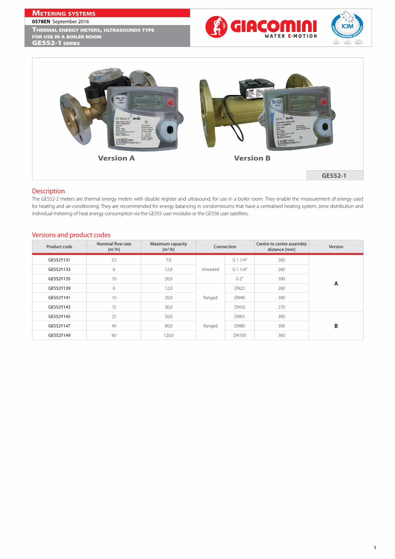
DescriptionThe GE552-2 meters are thermal energy meters with double register and ultrasound, for use in a boiler room. They enable the measurement of energy used for heating and air-conditioning. They are recommended for energy balancing in condominiums that have a centralised heating system, zone distribution and individual metering of heat energy consumption via the GE555 user modules or the GE556 user satellites.
Versions and product codes
Product code Nominal flow rate[m3/h]
Maximum capacity[m3/h] Connection Centre to centre assembly
distance [mm] Version
GE552Y131 3,5 7,0
threaded
G 1 1/4” 260
A
GE552Y133 6 12,0 G 1 1/4” 260
GE552Y135 10 20,0 G 2" 300
GE552Y139 6 12,0
flanged
DN25 260
GE552Y141 10 20,0 DN40 300
GE552Y143 15 30,0 DN50 270
GE552Y145 25 50,0
flanged
DN65 300
BGE552Y147 40 80,0 DN80 300
GE552Y149 60 120,0 DN100 360
Version A Version B
GE552-1

2
0578EN September 2016Metering systeMs
Thermal energy meTers, ulTrasounds Typefor use in a boiler roomge552-1 series
Main characteristics• Class 2 in accordance with EN 1434, PTB Class C.• Max. temperature 130 °C, PN16.• Temperature probes included:
- for DN25, DN32, DN40: pair of PT100 probes with housing, of the THF50 2-wire type (pocket short, L=50 mm, silicone cable length 1,75 m).- for DN50: pair of PT100 probes, of the PC121-2-30 2-wire type (pocket, L= 105 mm, cable length 3 m).
• Kit of housings included.• M-Bus card + 2 water meter inputs included.• Cable length (hydraulic, with electronic integrator): 1,5 m.• Power supply: lithium battery, effective life 12 years.• Size unit: Energy MW/h / Flow rate m3/h.• Electronic integrator protection: IP64.• Meter position: on the return line.• Horizontal or vertical installation in the return pipes of heating, cooling and combined systems.
Calculator characteristics (electronic part)• Temperature range 0-180 °C• Temperature difference 3-160 K• Temperature probes: PT100 (2 wires)• Backup memory: EEPROM• Display: LCD - 7 figures• Optic interface: EN 60870-5 / M-Bus protocol• Power supply: lithium battery, 12-year lifespan.
Advantages• Precise measuring of high and low flow rates.• Suitable for communication - Easy to read.
Advanced functionsThe meter offers a series of advanced functions such as the registration of data for complex network analyses, the registration of consumption peaks and so on to provide effective diagnosis tools for network management.All the available data are presented on an ergonomic, multi-purpose display.
Technical data
Product code
GE5
52Y1
31
GE5
52Y1
33
GE5
52Y1
35
GE5
52Y1
39
GE5
52Y1
41
GE5
52Y1
43
Ambient temperature [°C] 5÷55
Storage temperature [°C] -20÷60
Maximum flow rate [m3/h] 7,0 12,0 20,0 12,0 20,0 30,0
Nominal flow rate [m3/h] 3,5 6 10 6 10 15
Minimum flow rate [l/h] 35 60 100 60 100 150
Water temperature(heat./cool.) [°C] 5÷130
Losses of Pressure
0,1
1
10
1 10 100Q [m3/h]
Δp
[bar
]
Kv 10 Kv 16
Kv 32
Product code Nominal flow rate [m3/h] Kv
GE552Y131 3,5 10
GE552Y133 6 16
GE552Y135 10 32
GE552Y139 6 16
GE552Y141 10 32
GE552Y143 15 32
Supplementary card:M-Bus + 2 inputs for external water metersM-Bus• Reference Standard: EN 1434-3• Baud rate: from 300 to 2400 baud• Data in standard mode: Energy - Volume - Flow rate - Temperatures (delivery, return, difference) - Time spent in error - Operating time - Date and time - Water meter water volumes - Firmware version
Impulse inputs for water meters• Impulse value (regardless of the input): 1 / 2,5 / 10 / 25 / 100 / 250 / 1000 litres/impulse• Impulse measurement: Closed contact R≤500 Ω Open contact R≤100 kΩ Maximum frequency: 10 Hz
Product code Nominal flow rate[m3/h]
Maximum capacity[m3/h] Connection Centre to centre assembly
distance [mm] Version A
GE552Y131 3,5 7,0
threaded
G 1 1/4” 260
GE552Y133 6 12,0 G 1 1/4” 260
GE552Y135 10 20,0 G 2" 300
GE552Y139 6 12,0
flanged
DN25 260
GE552Y141 10 20,0 DN40 300
GE552Y143 15 30,0 DN50 270
GE552-1 VERSION A

3
0578EN September 2016Metering systeMs
Thermal energy meTers, ulTrasounds Typefor use in a boiler roomge552-1 series
Multi-purpose displayThe multi-purpose display facilitates reading, making it easier to access the cost data and allowing you to diagnose the fault alarms straight away.The long-life LCD display has a button for accessing the various operating levels (level).
1 2 3 4 5
9
6
7
8
10111213
14
Legend
1 Alarm icon 8 Decimal
2 Dirt warning 9 Impulse input value
3 Temperatures 10 Peaks
4 Flow rate indicator 11 Lapsed time indicator
5 Date and time figures 12 Thresholds
6 Loop indicator 13 External water meters
7 Size unit 14 Main figures
Display navigation levelsLevel 1 - Cost dataEnergyCooling energy (optional)VolumeLCD testExternal meter for water 1/2 (optional)
Level 2- Additional informationFlow ratePowerDelivery temperatureReturn temperatureTemperature differenceOperating timeDate + time at maximum power (optional)Date + time at maximum flow rate (optional)Date + time at maximum temperature (optional)Time alarmTemperature alarmFlow rate alarmOverflow alarmEnergy supply alarmCurrent date and time (optional)Primary M-Bus addressSecondary M-Bus addressM-Bus Baud rateImpulse value on water meter 1/2 (optional)
Level 3- Fixed date readingEnergy at fixed date 1...13Cooling energy at fixed date 1...13Volume at fixed date 1...13Water meter at fixed date 1/2 1...13 (optional)Software version
Dimensions
Compliance and Normative references• MID 2004/22/EC Module B+D• Class 2.0, complying with EN 1434• Environmental class C, complying with EN 1434• OIML R75• PTB Class C• Test SP ≤ -2%• PED conformity
Compliance with MID DirectiveIf used for commercial applications, the energy meters are classified as measuring instruments subject to the rules of legal metrology. The GE552-1 boiler room meters comply with the requisites of Directive 2004/22/EC on measuring instruments (MID Directive - Measurement Instrument Directive), implemented in Italy by Legislative Decree 2 February 2007, no. 22 (Official Gazette no. 64 of 17 March 2007). The certificate of conformity was issued by the PTB Institute of Metrology (Physikalisch-Technische Bundesanstalt).
CalculatorWall installation
Meter body
Product code DN A [mm] B [mm] flange Ø
GE552Y131 25 77 23 -
GE552Y133 25 77 23 -
GE552Y135 40 85 35 -
GE552Y139 25 77 23 110
GE552Y141 40 85 35 140
GE552Y143 50 85 - 160
Note.The supplementary metrological marking is displayed on the front of each device, next to the EC mark; it consists of an “M” plus the last two digits of the year of marking, surrounded by a rectangle.

4
0578EN September 2016Metering systeMs
Thermal energy meTers, ulTrasounds Typefor use in a boiler roomge552-1 series
Main characteristicsVolumetric measurer with ultrasound:• Complying with R45 Class 4, EN 1434 Class 2, PTB Class C.• Type-approved in accordance with MID directive (2004/22/EC).• PN25.• Power supply: battery, via the calculation unit.• Protection class: IP68.• Meter position: on the return line.• Impulse weight: 25 litres/impulse.• Horizontal or vertical installation in the return pipes of heating, cooling and combined systems.
Calculator characteristics (electronic part)• Temperature range 0÷180 °C• Temperature difference 3÷160 K• Ambient temperature range 5÷55 °C• Temperature probes: PT100 (2 wires)• Kit of housings included.• Backup memory: EEPROM• Display: LCD - 7 figures• Power supply: lithium battery, effective life 12 years.• Size unit: MW/h, m3/h.• Meter position: on the return line.• Impulse value (programmable): 1 / 2,5 / 10 / 25 / 100 / 250 / 1000 l• Optic interface: EN 60870-5 / M-Bus protocol• M-Bus card + 2 water meter inputs included.• Length of the cable: 5 m
Technical dataProduct code GE552Y145 GE552Y147 GE552Y149
Ambient temperature [°C] 5÷55
Storage temperature [°C] -20÷60
Maximum flow rate [m3/h] 50 80 120
Nominal flow rate [m3/h] 25 40 60
Minimum flow rate [l/h] 250 400 600
Water temperature(heat./cool.) [°C] 5÷120
Characteristics of the impulse output• Version: collector open (drain)• Polarity: not reversible• Impulse length: 100 ms ±10%• Maximum input voltage: 30 V DC• Maximum input current: 20 mA• Maximum output frequency: 150 Hz
Electricity supply• Nominal voltage: 3,0...5,5 V DC• Average current consumption: < 100 mAh per year• Peak current consumption Imax: < 10 mA• The volumetric measurer with ultrasound is powered directly from the calculator, via its battery.
Losses of Pressure
0,01
0,1
1
10 100 1000Q [m3/h]
Δp
[bar
]Kv 90 Kv 140 Kv 200
Product code Nominal flow rate [m3/h] Kv
GE552Y145 25 90
GE552Y147 40 140
GE552Y149 60 200
Supplementary card:M-Bus + 2 inputs for external water metersM-Bus• Reference Standard: EN 1434-3• Baud rate: from 300 to 2400 baud• Data in standard mode: Energy - Volume - Flow rate - Temperatures (delivery, return, difference) - Time spent in error - Operating time - Date and time - Water meter water volumes - Firmware version
Impulse inputs for water meters• Impulse value (regardless of the input): 1 / 2,5 / 10 / 25 / 100 / 250 / 1000 litres/impulse• Impulse measurement: Closed contact R≤500 Ω Open contact R≤100 kΩ Maximum frequency: 10 Hz
Product code Nominal flow rate[m3/h]
Maximum capacity[m3/h] Connection Centre to centre assembly
distance [mm] Version B
GE552Y145 25 50,0
flanged
DN65 300
GE552Y147 40 80,0 DN80 300
GE552Y149 60 120,0 DN100 360
GE552-1 VERSION B

5
0578EN September 2016Metering systeMs
Thermal energy meTers, ulTrasounds Typefor use in a boiler roomge552-1 series
Multi-purpose displayThe multi-purpose display facilitates reading, making it easier to access the cost data and allowing you to diagnose the fault alarms straight away.The long-life LCD display has a button for accessing the various operating levels (level).
1 2 3 4 5
9
6
7
8
10111213
14
Legend
1 Alarm icon 8 Decimal
2 Dirt warning 9 Impulse input value
3 Temperatures 10 Peaks
4 Flow rate indicator 11 Lapsed time indicator
5 Date and time figures 12 Thresholds
6 Loop indicator 13 External water meters
7 Size unit 14 Main figures
Display navigation levelsLevel 1 - Cost dataEnergyCooling energy (optional)VolumeLCD testExternal meter for water 1/2 (optional)
Level 2- Additional informationFlow ratePowerDelivery temperatureReturn temperatureTemperature differenceOperating timeDate + time at maximum power (optional)Date + time at maximum flow rate (optional)Date + time at maximum temperature (optional)Time alarmTemperature alarmFlow rate alarmOverflow alarmEnergy supply alarmCurrent date and time (optional)Primary M-Bus addressSecondary M-Bus addressM-Bus Baud rateImpulse value on water meter 1/2 (optional)
Level 3- Fixed date readingEnergy at fixed date 1...13Cooling energy at fixed date 1...13Volume at fixed date 1...13Water meter at fixed date 1/2 1...13 (optional)Software version
Dimensions
Compliance and Normative references• MID 2005/22/EC• Class 2.0, complying with EN 1434• Environmental class C, complying with EN 1434• PTB approved
Compliance with MID DirectiveIf used for commercial applications, the energy meters are classified as measuring instruments subject to the rules of legal metrology. The GE552-2 boiler room meters comply with the requisites of Directive 2004/22/EC on measuring instruments (MID Directive - Measurement Instrument Directive), implemented in Italy by Legislative Decree 2 February 2007, no. 22 (Official Gazette no. 64 of 17 March 2007). The certificate of conformity was issued by the PTB Institute of Metrology (Physikalisch-Technische Bundesanstalt).
CalculatorWall installation
Meter body
Product code GE552Y145 GE552Y147 GE552Y149
Body length L1 [mm] 300 300 360
Electronic length L2 [mm] 90 90 90
Electronic width B [mm] 65,5 65,5 65,5
nominal Ø 65 80 100
Height A [mm] 79 86,5 95,5
Height A2 [mm] 85 92,5 108
flange Ø [mm] 184 200 235
Centre distance of holes K [mm] 145 160 190
Hole Ø L [mm] 18 18 22
Number of holes 8 8 8
Flange dimension F [mm] 170 185 216
Note.The supplementary metrological marking is displayed on the front of each device, next to the EC mark; it consists of an “M” plus the last two digits of the year of marking, surrounded by a rectangle.
6
0578EN September 2016Metering systeMs
Thermal energy meTers, ulTrasounds Typefor use in a boiler roomge552-1 series
Product specificationsGE552-1 ENERGY METERS FOR USE IN A BOILER ROOMGE552Y131Thermal energy meter with ultrasound, for use in a boiler room. Threaded connections 1 1/4”. Nominal flow rate 3,5 m³/h. Consisting of an electronic calculation and display unit, a flow rate measuring section, and two PT100 temperature probes complete with housings. Two inputs for connecting the water meters with the impulse output. M-Bus communication interface. Assembly in “split” mode. Complying with Directive 2004/22/EC (MID). Battery-powered (effective life 12 years). Electronic calculator protection: IP64. Centre distance for assembly 260 mm. Max. temperature 130 °C. PN16.
GE552Y133Thermal energy meter with ultrasound, for use in a boiler room. Threaded connections 1 1/4”. Nominal flow rate 6,0 m³/h. Consisting of an electronic calculation and display unit, a flow rate measuring section, and two PT100 temperature probes complete with housings. Two inputs for connecting the water meters with the impulse output. M-Bus communication interface. Assembly in “split” mode. Complying with Directive 2004/22/EC (MID). Battery-powered (effective life 12 years). Electronic calculator protection: IP64. Centre distance for assembly 260 mm. Max. temperature 130 °C. PN16.
GE552Y135Thermal energy meter with ultrasound, for use in a boiler room. Threaded connections 2”. Nominal flow rate 10,0 m³/h. Consisting of an electronic calculation and display unit, a flow rate measuring section, and two PT100 temperature probes complete with housings. Two inputs for connecting the water meters with the impulse output. M-Bus communication interface. Assembly in “split” mode. Complying with Directive 2004/22/EC (MID). Battery-powered (effective life 12 years). Electronic calculator protection: IP64. Centre distance for assembly 300 mm. Max. temperature 130 °C. PN16.
GE552Y139Thermal energy meter with ultrasound, for use in a boiler room. Flanged connections DN25. Nominal flow rate 6,0 m³/h. Consisting of an electronic calculation and display unit, a flow rate measuring section, and two PT100 temperature probes complete with housings. Two inputs for connecting the water meters with the impulse output. M-Bus communication interface. Assembly in “split” mode. Complying with Directive 2004/22/EC (MID). Battery-powered (effective life 12 years). Electronic calculator protection: IP64. Centre distance for assembly 260 mm. Max. temperature 130 °C. PN16.
GE552Y141Thermal energy meter with ultrasound, for use in a boiler room. Flanged connections DN40. Nominal flow rate 10,0 m³/h. Consisting of an electronic calculation and display unit, a flow rate measuring section, and two PT100 temperature probes complete with housings. Two inputs for connecting the water meters with the impulse output. M-Bus communication interface. Assembly in “split” mode. Complying with Directive 2004/22/EC (MID). Battery-powered (effective life 12 years). Electronic calculator protection: IP64. Centre distance for assembly 300 mm. Max. temperature 130 °C. PN16.
GE552Y143Thermal energy meter with ultrasound, for use in a boiler room. Flanged connections DN50. Nominal flow rate 15,0 m³/h. Consisting of an electronic calculation and display unit, a flow rate measuring section, and two PT100 temperature probes complete with housings. Two inputs for connecting the water meters with the impulse output. M-Bus communication interface. Assembly in “split” mode. Complying with Directive 2004/22/EC (MID). Battery-powered (effective life 12 years). Electronic calculator protection: IP64. Centre distance for assembly 270 mm. Max. temperature 130 °C. PN16.
GE552Y145Thermal energy meter with ultrasound, for use in a boiler room. Flanged connections DN65. Nominal flow rate 25,0 m³/h. Consisting of an electronic calculation and display unit, a flow rate measuring section, and two PT100 temperature probes complete with housings. Two inputs for connecting the water meters with the impulse output. M-Bus communication interface. Assembly in “split” mode. Complying with Directive 2004/22/EC (MID). Battery-powered (effective life 12 years). Electronic calculator protection: IP64. Centre distance for assembly 300 mm. Max. temperature 120 °C. PN25.
GE552Y147Thermal energy meter with ultrasound, for use in a boiler room. Flanged connections DN80. Nominal flow rate 40,0 m³/h. Consisting of an electronic calculation and display unit, a flow rate measuring section, and two PT100 temperature probes complete with housings. Two inputs for connecting the water meters with the impulse output. M-Bus communication interface. Assembly in “split” mode. Complying with Directive 2004/22/EC (MID). Battery-powered (effective life 12 years). Electronic calculator protection: IP64. Centre distance for assembly 300 mm. Max. temperature 120 °C. PN25. GE552Y149Thermal energy meter with ultrasound, for use in a boiler room. Flanged connections DN100. Nominal flow rate 60,0 m³/h. Consisting of an electronic calculation and display unit, a flow rate measuring section, and two PT100 temperature probes complete with housings. Two inputs for connecting the water meters with the impulse output. M-Bus communication interface. Assembly in “split” mode. Complying with Directive 2004/22/EC (MID). Battery-powered (effective life 12 years). Electronic calculator protection: IP64. Centre distance for assembly 300 mm. Max. temperature 120 °C. PN25.
Additional informationFor additional information please check the website www.giacomini.com or contact the technical service: ' +39 0322 923372 6 +39 0322 923255 * [email protected] pamphlet is merely for information purposes. Giacomini S.p.A. retains the right to make modifications for technical or commercial reasons, without prior notice, to the items described in this pamphlet. The information described in this technical pamphlet does not exempt the user from following carefully the existing regulations and norms on good workmanship.Giacomini S.p.A. Via per Alzo, 39 - 28017 San Maurizio d’Opaglio (NO) Italy