Embed Size (px)
Citation preview

A Ship Design Procedure
By Thomas Lamb1
The small number of published articles on the subject of practical ship design suggests that naval architects are reluctant to discuss this most important part of the overall ship production sequence. It is felt that constant discussion of all aspects of ship design would enable progress to be made in what, at the moment, is an empirical art. A ship design procedure is therefore presented in the hope that it will provide a basis for discussion. Each stage in the procedure is discussed in detail in separate sections and both standard forms and data are given. An example is included to illustrate the use of the forms and data.
Introduction AT PRESENT there is no generally accepted ship design procedure in existence. Individual naval architects would probably set about the task of designing a ship in a number of different ways. Naturally, the methods they would use are the fruits of their own experience or perhaps that of someone else who gave away the information in a moment of weakness. This is said because, although there have been a number of papers on ship design technique [1-4]2 over the past decade, the number is very small considering how many people are engaged in ship design. This suggests that naval architects are reluctant to discuss the design methods and data they use, which is most unfortunate, as the design of a ship is the most important part of the overall production sequence, and constant review and discussion of all aspects of design can only result in benefit to the shipbuilding industry as a hole.
With this in mind, a ship design procedure detailing the calculations required from the time of receiving a shipowner’s requirements through the preparation of the bidding documents is presented in the hope that it will provide a basis for worthwhile discussion.
There is also a selfish reason. Most of the work required for the paper has been collected and arranged in the author’s free time during the past few years and he has been unable to find the time to keep as up to date as he would have liked. Therefore, it is his hope that naval architects engaged in the many specialist areas used by ship designers will come forward and suggest improvements to the proposed procedure for his benefit if for no one else.
__________
1 Assistant Chief Naval Architect, Maryland Shipbuilding & Drydock Company, Baltimore, Md. 2 Numbers in brackets designate References at the end of paper.
Presented at the September 1968 Meeting of the Chesapeake Section of THE SOCIETY OF NAVAL ARCHITECTS AND MARINE ENGINEERS. The use of computers for certain ship calculations is commonplace today and it may therefore appear to be behind the times to discuss techniques which do not utilize computers. However, as far as the author is aware, there is no complete design program in use at the moment, although there are many people working on complete design through production programs for computer application, and the time may come when every ship will be produced in this way. It is possible to use computers to examine many solutions to a given set of requirements quickly; therefore, existing design programs are usually of the optimization type. They are of the form, at the moment, that even after the optimum particulars are determined it is still necessary to carry out all the calculations in the proposed procedure. Also, before programming a complete design procedure, it is necessary to re-examine the methods used to perform the calculations involved and the relationship between them. It is hoped that the paper will be a step in this direction.
The use of the proposed procedure would provide the naval architect with all the information required to confidently prepare the contract design documents. If the ship should be built, no further design calculations would be necessary and the engineering departments could commence preparation of the working drawings and ordering of materials as soon as the contract is signed. If model resistance tests are desired, a fair lines plan could be quickly drawn from the preliminary body plan. It would still be necessary to prepare the detailed hydrostatic, stability particulars and capacities during the building of the ship. However, the justification, if any is needed, for considering all the items proposed in the design stage is that it would ensure that the ship as de-signed would satisfy all the specified conditions, if built.
General Appraisal of Design Problem

A SHIP DESIGN PROCEDURE LAMB
The design of a ship by a naval architect is not the initial action in this evolution. Before the actual design calculations can be started, it is necessary to know what type, deadweight, capacity and speed of ship are required. These are chosen by the shipowner after examination of the trade in which the proposed ship is to operate. This examination may only be an analysis of existing ships in the trade in order to determine where improvements could be made. On the other hand, it may be a complete ship operating economics investigation.
Although it should be the aim of every ship designer to determine the optimum design for a given set of requirements, this is not done at present to any large extent. This is because most ship designers do not have sufficient time to examine, by manual methods, the number of design combinations necessary for optimization.
Depending upon his position and place of employment, the function of a naval architect can vary from the design of ships from the minimum of specified requirements to the checking of a complete design prepared by someone else. In either case, the order in which the work can be carried out is the same, the only difference being that the values are either to be determined or checked.
For effective control and planning, it is essential that a standard design procedure be adopted. As ship design involves many repetitive calculations, much time can be saved by the use of standard calculation forms, even for the simplest calculations. The use of standard forms also ensures adherence to the adopted procedure and enables the average time taken for each calculation in the procedure to be determined. This, in turn, enables the naval architect to estimate the time required to complete the project. The proposed procedure is as follows:
Preliminary Design (determination or check of dimensions, power, deadweight, capacity, stability and seakindness)
Detailed Resistance and Propulsion Estimate Sketch General Arrangement (including preliminary
subdivision if considered necessary) Preparation of Preliminary Body Plan Displacement and LCB Check Preliminary Hydrostatics Preliminary Cargo and Tank Capacities Preliminary Light Ship Weights and Centers Preliminary Trim and Stability Preparation of General Arrangement Tonnage Estimate Preparation of Scantlings Plans Detailed Weights and Centers Revised Trim and Stability ( including cross curves of
stability) Longitudinal Strength Preparation of Specifications Presentation of Technical Data
If the complete design is to be prepared by one designer, the foregoing sequence could be adhered to. However, it is usual for a team to work on the project; therefore, the first three items would be calculated by the naval architect and the remainder of the work divided between three designers as shown in Fig. 1, which is a flow diagram of the proposed procedure.
Each stage in the design procedure will be further discussed in separate sections. An example is given to illustrate the use of the forms and the data. The outline specification for the example is given in the Appendix.
Fig. 1. Flow diagram of design procedure
Preliminary Design Calculations It is the purpose of the preliminary design calculations to determine dimensions, hull form and power to satisfy given speed, capacity, deadweight and endurance requirements. The purpose of the detailed design calculations which follow the preliminary design calculations is to check that the particulars determined in the preliminary stage satisfy the specified requirements and also to develop, in detail, a design capable of meeting the special requirements desired.
MARINE TECHNOLOGY, OCTOBER 1969, pp. 362-405

A SHIP DESIGN PROCEDURE LAMB
The preliminary design stage is thus the “cornerstone” of the whole procedure. If this stage does not consider all the important items or if the data on which the calculations are based are inadequate for the purpose, it is probable that modifications to the preliminary determined
values will be found necessary as the detailed design progresses, The amount of repetition of detailed design calculations, and therefore wasted time, will depend on the stage in the design procedure at which the inadequacy is discovered.
Fig. 2. Diagram showing interdependence of parameters in preliminary design
The calculations made in the preliminary design stage can be quite complicated due to the interdependence of the various factors involved, as shown if Fig. 2. To avoid time-wasting repetition, the order of the calculations must be arranged so that each step logically follows the previous steps and only uses values determined in these steps.
It is of great assistance to have a summary sheet on which the specified particulars are entered before the design commences and, as each stage in the design
calculations is completed, the relevant values determined are entered on the sheet. The summary then acts as a reference, comparison and progress sheet during the period of the design. Form I is a summary sheet suitable for this purpose. (All the forms referred to appear in the Appendix.).
It is possible to derive suitable dimensions for a design by considering only three sets of parameters, but it is not possible to say from such an examination that the resulting design is the optimum design.
___________________________________ Nomenclature ___________________________________
The symbols listed herein are used in the paper without further description. Others abbreviations and symbols which are not given in the Nomencaleture are identified elsewhere in the paper.
C1 =ηp =
dhp =
shp =
ship correlation factorpropulsive efficiencydelivered horsepower or power delivered to propellershaft horsepower
BMT =
A =kT =
Height of transverse metacenter above VCBarea (i.e., waterplane area)transverse radius of gyration of waterplane
LBP = length between perpendiculars Cb = block coefficient d = draft
L = length between perpendiculars in formulas
shpmc = maximum continuous shaft horsepower
KL = longitudinal radius of gyration of the ship’s mass
B = breadth molded of ship GMT = transverse metacentric height s = specific gravity of salt water
D = depth molded to uppermost continuous deck
ENs = equipment numeral for superstructures = 0.85 x Σ(ls x hs)
KMT = height of metacenter above keel or baseline
dwt = deadweight ls and hs = superstructure total length andheight respectively
Cvm = coefficient to take account of added mass in heaveLCB = longitudinal center of buoyancy
ehp = effective horsepower VCB = vertical center of buoyancy CPP = controllable-pitch propeller
© = resistance coefficient = 427.1 x ehp / Vs
3 x Δ2/3ENd = Equipment numeral for deckhouses
= 0.75 x Σ(ld x hd)c = coefficient to take account of
added mass in pitch
Vs = service speed, knots ld and hd = deckhouse total length and height respectively
N or rpm = revolutions per minute of propellerΔ = displacement, long tons (2240 lb)
MARINE TECHNOLOGY, OCTOBER 1969, pp. 362-405

A SHIP DESIGN PROCEDURE LAMB
= volume of displacement m = mass of the ship
Fig. 3 - Design guidelines for open shelter deck vessels
To optimize a design using manual methods, it is estimated that the preliminary design calculations would need to be made for about 256 different combinations of the parameters involved. The advantages to be gained by using a computer for preliminary design calculations are obvious. However, although the existing manual methods could be programmed, this would not take full advantage of a computer’s capabilities. It is necessary to re-examine the calculations involved and their relationship to each other. When the optimum design particulars have been determined from a computer program, it is prudent to check them. The same forms that are proposed for the manual preliminary design calculations can be used for such a check.
Form II is used for the preliminary design calculations with Form III or Form IV3 determining the minimum freeboard, depending on the ship type. The use of these forms and the data presented will be described in the following sections.
Selection or Check of Dimensions The minimum specified requirements on which a naval architect can base a design are deadweight, cargo capacity, endurance, and trial or service speed. If either
the deadweight or the cargo capacity is not specified, he must select a suitable stowage factor to derive the un-specified parameter. Table 1 gives stowage factors for recent ships of different types. If, on the other hand, a complete design is to be checked, it would be necessary to compare the dimensions given with usual good prac-tice unless there is a given reason why this will not be so.
As an aid to making such a check and also as guidance for original design, it is worthwhile to plot LBP on a base of deadweight for different types of ships as shown in the top left hand diagram in Figs. 3-7. In the case of refrigerated ships it is more useful to plot LBP on a base of net bin refrigerated capacity such as Fig. 8. The advantage of this form of recording ship data is that it can be easily kept up to date, as only the deadweight or cargo capacity and LBP are required and these are usually given for every ship described in technical literature.
To commence a design for which the aforementioned specified data has been given with no restrictions on dimensions, maximum and minimum values of LBP are lifted from the appropriate curves and entered with a suitable mean value in the columns on Form II. The breadth B and the depth D can be selected from the ratios L/B and L/D or B/D as given in the diagrams in Figs. 3-7.
MARINE TECHNOLOGY, OCTOBER 1969, pp. 362-405

A SHIP DESIGN PROCEDURE LAMB
__________ 3 Form IV (omitted) is similar to Form III with the tables changed as necessary.
Fig. 4 - Design guidelines for full scantling vessels
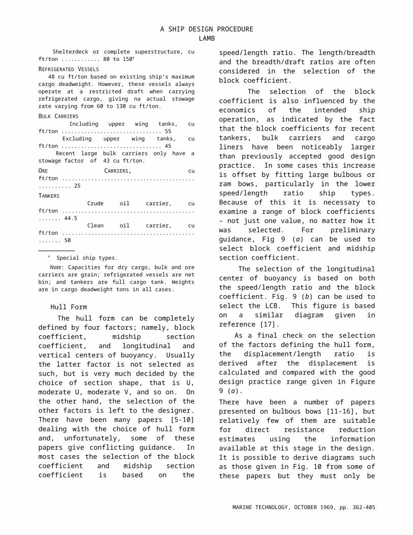
Table 1 – Typical Ship Stowage FactorsDRY CARGO SHIPS Full scantling, cu ft/ton .................................................... 55 minimum Shelterdeck or complete superstructure, cu ft/ton ............ 80 to 150a
REFRIGERATED VESSELS 48 cu ft/ton based on existing ship’s maximum cargo deadweight. However, these vessels always operate at a restricted draft when carrying refrigerated cargo, giving na actual stowage rate varying from 60 to 130 cu ft/ton.
BULK CARRIERS Including upper wing tanks, cu ft/ton ............................... 55 Excluding upper wing tanks, cu ft/ton ............................... 45 Recent large bulk carriers only have a stowage factor of 43 cu ft/ton.
ORE CARRIERS, cu ft/ton ................................................... 25
TANKERS Crude oil carrier, cu ft/ton ................................................ 44.5 Clean oil carrier, cu ft/ton ................................................ 50__________ a Special ship types.
Note: Capacities for dry cargo, bulk and ore carriers are grain; refrigerated vessels are net bin; and tankers are full cargo tank. Weights are in cargo deadweight tons in all cases.
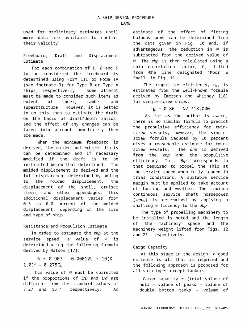
Hull Form The hull form can be completely defined by four factors; namely, block coefficient, midship section
coefficient, and longitudinal and vertical centers of buoyancy. Usually the latter factor is not selected as such, but is very much decided by the choice of section shape, that is U, moderate U, moderate V, and so on. On the other hand, the selection of the other factors is left to the designer. There have been many papers [5-10] dealing with the choice of hull form and, unfortunately, some of these papers give conflicting guidance. In most cases the selection of the block coefficient and midship section coefficient is based on the speed/length ratio. The length/breadth and the breadth/draft ratios are often considered in the selection of the block coefficient.
The selection of the block coefficient is also influenced by the economics of the intended ship operation, as indicated by the fact that the block coefficients for recent tankers, bulk carriers and cargo liners have been noticeably larger than previously accepted good design practice. In some cases this increase is offset by fitting large bulbous or ram bows, particularly in the lower speed/length ratio ship types. Because of this it is necessary to examine a range of block coefficients – not just one value, no matter how it was selected. For preliminary guidance, Fig 9 (a) can be used to select block coefficient and midship section coefficient.
MARINE TECHNOLOGY, OCTOBER 1969, pp. 362-405

A SHIP DESIGN PROCEDURE LAMB
The selection of the longitudinal center of buoyancy is based on both the speed/length ratio and the block coefficient. Fig. 9 (b) can be used to select the LCB. This figure is based on a similar diagram given in reference [17].
As a final check on the selection of the factors defining the hull form, the displacement/length ratio is derived after the displacement is calculated and compared with the good design practice range given in Figure 9 (a).
There have been a number of papers presented on bulbous bows [11-16], but relatively few of them are suitable for direct resistance reduction estimates using the information available at this stage in the design. It is possible to derive diagrams such as those given in Fig. 10 from some of these papers but they must only be used for preliminary estimates until more data are available to confirm their validity.
Freeboard, Draft and Displacement Estimate For each combination of L, B and D to be considered the freeboard is determined using Form III or Form IV (see footnote 3) for Type B or Type A ships, respective-ly. Some attempt must be made to consider such items as extent of sheer, camber and superstructure. However, it is better to do this than to estimate the draft on the basis of draft/depth ratios, and the effect of any changes can be taken into account immediately they are made.
When the minimum freeboard is derived, the molded and extreme drafts can be determined and if necessary modified if the draft is to be restricted below that determined. The molded displacement is derived and the full displacement determined by adding to the molded displacement, the displacement of the shell, cruiser stern, and other appendages. This additional displacement varies from 0.3 to 0.8 percent of the molded displacement, depending on the size and type of ship.
Resistance and Propulsion Estimate In order to estimate the ehp at the service speed, a value of © is determined using the following formula derived by Watson [17]:
© = 0.907 – 0.00012L + 10(K – 1.0)2 – 0.275Cb
This value of © must be corrected if the proportions of L/B and L/d are different from the standard values of 7.27 and 15.4, respectively. An estimate of the effect of fitting bulbous bows can be determined from the data given in Fig. 10 and, if advantageous, the reduction in © is subtracted from the derived value of ©. The ehp is then calculated using a ship correlation factor, C1, lifted from the line designated “Moor & Small” in Fig. 11.
The propulsive efficiency, ηp, is estimated from the well-known formula derived by Emerson and Whitney [18] for single-screw ships:
ηp = 0.86 - N√L/18,000 As far as the author is aware, there is no similar formula to predict the propulsive efficiency for twin-screw vessels; however, the single-screw formula reduced by 10 percent gives a reasonable estimate for twin-screw vessels. The dhp is derived from the ehp and the propulsive efficiency. This dhp corresponds to that required to propel the ship at the service speed when fully loaded in trial conditions. A suitable service margin must be applied to take account of fouling and weather. The maximum continuous service shaft horsepower (shpmc) is determined by applying a shafting efficiency to the dhp.
The type of propelling machinery to be installed is noted and the length of the machinery space and the machinery weight lifted from Figs. 12 and 21, respectively.
Cargo Capacity At this stage in the design, a good estimate is all that is required and the following approach is proposed for all ship types except tankers:
Cargo capacity = (total volume of hull – volume of peaks – volume of double bottom tanks – volume of machinery space) capacity coefficient
Total volume of hull =
Volume of peaks =
Volume of double-bottom tanks =
Volume of machinery space =
Volume of shaft tunnel =
Volume between tunnel flat and tank top
=
Volume of bulk carrier bottom wing tanks above tank top =
Volume of bulk carrier upper wing tanks=
MARINE TECHNOLOGY, OCTOBER 1969, pp. 362-405

A SHIP DESIGN PROCEDURE LAMB
Fig. 5 - Design guidelines for tankers
Fig. 6 - Design guidelines for bulk carriers
MARINE TECHNOLOGY, OCTOBER 1969, pp. 362-405
A SHIP DESIGN PROCEDURE LAMB
Fig. 7 - Design guidelines for coasters
Fig. 8 - Design guidelines for refrigerated cargo ships
MARINE TECHNOLOGY, OCTOBER 1969, pp. 362-405
A SHIP DESIGN PROCEDURE LAMB
Fig. 9 – Form parameters
whereSf = sheer forwardSa = sheer aftCr = camber on uppermost continuous deckK1 = hull capacity coefficient
lp = combined length of fore and aft peaksK2 = peak capacity coefficientDtt = depth of double bottomK3 = double bottom capacity coefficientler = length of machinery space
Der = depth to top of machinery spaceK4 = machinery space capacity coefficient
lt = length of shaft tunnelDt = depth to tunnel topbt = tunnel breadth
K5 = tunnel capacity coefficientlbwt = length of bottom wing tanksbbwt = breadth at tank top level, one side onlyhbwt = height of bottom wing tank above tank topluwt = length of upper wing tanksbuwt = breadth of upper wing tank at deck, one side onlyhuwt = height of bottom wing tank above tank topK6 = bottom wing tank capacity coefficientK7 = Upper wing tank capacity coefficient
For tankers, a good estimate of tank capacity can be obtained from the following formula:
Tanker cargo capacity = (Cb –0.005)LBD –0.65lerBDValues of the foregoing coefficients and overall capacity coefficients are given in Table 2.
Table 2 – Capacity Coefficients
Hull capacity coefficient ....................... K1 = 1.03 at Cb = 0.50K1 = 1.13 at Cb = 0.80
Peak capacity coefficient ...................... K2 = 0.37
Double-bottom capacity coefficient ...... K3 = 0.60 for Cb = 0.55K3 = 0.90 for Cb = 0.80
Machinery space capacity coefficientamidship position .............................. K4 = 1.35 for Cb < 0.70⅔ aft position (aft bulkhead station 2) K4 = 0.95/Cb for Cb 0.70aft position ........................................ K4 = 0.85
Tunnel capacity coefficientamidship machinery space ................ K5 = 0.73⅔ aft machinery space ...................... K5 = 0.60
Bulk carrier wing tank capacity coefficientbottom wing tank ............................. K6 = 1.10upper wing tank ............................... K7 = 1.40
Overall capacity coefficientgrain ................................................. 0.98bale ................................................... 0.90refrigerated net bin .......................... 0.72
Fig. 10 - Reduction in resistance coefficient for bulbous bows
Fig. 11 – Ship correlation factor
Fig. 12 – Length of machinery space
Fig. 13 – Hull net steel weight/equipment numeral coefficient
Fig. 14 – Steel weight reduction for reduced draft
Weight Estimate The deadweight of a ship is the difference between the displacement and the light ship weight. The light ship weight is the total weight of all the items necessary to construct and equip the ship ready for sea, but excludes the weight of fuel oil, fresh water, crew and effects, stores and provisions, which are considered as miscellaneous deadweight. The total deadweight is the
sum of the cargo deadweight, dunnage, if carried, and the miscellaneous deadweight already mentioned.
The light ship weight is divided into convenient groups, the most common being net steel, wood and outfit and machinery weight groups. However, the system presented divides the light ship weight into net steel, wood and outfit, hull engineering, and machinery weight groups. A detailed demarkation of the groups is given in Table 3.
MARINE TECHNOLOGY, OCTOBER 1969, pp. 362-405

A SHIP DESIGN PROCEDURE LAMB
Table 3 – Light Ship Weight System
Net Steel
1 Net SteelHull structural steel, superstructures and deckhouses, stern frame, rudder and rudder post, masts and masthouses.
Wood and Outfit
2 Hull Wood and Outfit Joinerwork, carpenter work, smithwork, rigging, steel hatch covers, special masts, cargo gear, deck machinery including steering gear, insulation (thermal and acoustic in casing and accommodation, refrigerated compartments, W.T. doors, etc
3 Machinery OutfitRefrigerating machinery (stores and cargo) air conditioning, heating and ventilation, fire detection and extinguishing equipment.
Hull Engineering
4 Hull Engineering Outside Machinery SpacesPiping, heating coils, sanitary system, scuppers and discharges, electrical installation.
5 Hull Engineering in Machinery SpacesPumps, piping, loose tanks, electrical installation, boilers in motor ships, gratings and ladders, funnel.
Machinery
6 MachineryMain propelling machinery, boilers with water in steam ships, auxiliaries for main machinery, generators, shafting, propellers.
The basis for estimating the net steel, wood and outfit, and hull engineering weights uses Lloyd’s equipment numeral given by
L(B + d) + 0.85(D’ – d) + 0.85(ls hs) + 0.75(ld hd),
in the following ways: for the net steel estimate, the equipment numerals for the hull, superstructure and deckhouses are kept separate. Curves of net steel weight coefficients on a base of LBP are given in Fig. 13 for full-scantling ships, bulk carriers, and tankers. The curves are drawn for a constant standard block coefficient for each ship type. The basic hull net steel weight is determined by multiplying the hull equipment numeral by the hull net steel weight coefficient. This basic weight must be corrected if the design block coefficient differs from the standard at the rate of ½ percent of the hull net steel weight for each 0.01 difference in block coefficient. If the design is to be of scantling draft type, it is necessary to correct the hull net steel weight determined for a full-scantling type. This scantling correction can be derived from Fig. 14. It is also necessary to apply the corrections given in Table 4 where they are appropriate.
If a complete design is being checked, corrections for differences in the number of bulkheads or decks can be
determined from the data given in Figs. 15, 16 and 17. These corrections can also be made for a new design if such differences are visualized at this stage.
The net steel weight of the superstructure and deckhouses can be determined from:
Superstructure (no internal steel) = 0.002 B ENs
Superstructure and deckhouses (with internal steel) = 0.0023 B (ENs or ENd)
To complete the net steel weight, na estimate of the weight of masts and masthouses is required. This can be derived from data given in Figs. 15, 16 and 17.
The wood and outfit and the hull engineering weights can be determined from Figs. 18 and 20, respectively, which are plots of these weights on a base of equipment numeral. Fig. 19 can be used to determine the additional wood and outfit weight for refrigerated cargo compartments, if fitted, on the basis of net bin capacity.
The weights for net steel, wood and outfit, hull engi-neering, and machinery are added together and a suitable margin applied to give the design light ship weight.
Table 4 – Diverse Corrections to Hull Steel Weight
PERCENTAG
E
ITEM CORRECTION All ship types for Ice Class I or A ............................................................. +8.0 for Ice Class II or B ............................................................ +4.0 for Ice Class III or C ........................................................... +2.0
Dry-Cargo Ships for heavy cargos in holds ................................................... +1.5 for each deck strengthened for heavy cargos ..................... +0.5
Bulk Carriers high tensile steel (using approximately 25% steel weight) ........................ -6.0 high tensile steel (using approximately 35% steel weight) ........................ -8.0 for strengthing for heavy cargos ........................................ +3.0 for strengthing for heavy cargos, alternate holds empty ... +4.0 for strengthing for ore cargos ............................................ +4.0 for strengthing for ore cargos, alterante holds empty ....... +5.5
Tankers high tensile steel (using approximately 35% steel weight) ....................... –8.0 use of an approved corrosion control system .................... –4.0 corrugated bulkheads in place of plane bulkheads ............ –1.7
Fig. 15 – Steel weight data sheet
Fig. 16 – Steel weight data sheet Fig. 17 – Steel weight data sheet
MARINE TECHNOLOGY, OCTOBER 1969, pp. 362-405

A SHIP DESIGN PROCEDURE LAMB
Stability Check
The stability of a ship can be unsuitable in two ways, too little and too much. Insufficient stability will restrict the operation of the ship and too much will cause the ship to be uncomfortable to the crew and may even cause damage to the cargo due to excessive motions at sea. Suitable ranges of a stability criterion, GMT/B, are given for different ship types in Table 5. These data are based on a diagram prepared by Roorda [19]. However, Bruhl [20] proposed that for ships with a breadth greater than 66 ft the value of GMT/B should not exceed 0.05, based on the relationship between the motions of a ship in a seaway.
Table 5 – Normal Range of GMT/BSHIP TYPE GMT/B
Passenger ships ........................................................ 0.040-0.050Large cargo ships ..................................................... 0.035-0.052Small cargo ships ..................................................... 0.040-0.055Tankers .................................................................... 0.060-0.092Ferries ...................................................................... 0.090-0.102Coasters ................................................................... 0.055-0.080Tugs ......................................................................... 0.060-0.080
The initial stability is examined by determining the BMT from a formula of the type A(kT)2/ and adding to this an estimate of the height of the center of bouyancy above the baseline to give KMT. An estimate for the height of the center of gravity of the ship in the condition to be considered is deducted from KMT to give the GMT. This can be compared with any specified value or, if there is none, the value can be divided by B and compared with the values of this ratio given in Table 5.
Seakeeping
In a seaway, a ship will roll, pitch, sway, heave, yaw and surge. These motions are usually considered independently but it is known that coupling between some of these motions does take place. The coupling between roll and pitch or heave gives rise to maximum motions, but coupling between pitch and heave can be used to give minimum motions at a particular point in the ship. However, this could not be done using the design data already determined in the preliminary design calculations. It is not likely to be attempted at even a later stage for normal merchant ships but it could be of interest in the problem of locating the reactor in a nuclear-propelled ship.
There does not seen to be any simple approach which considers ship motions and their coupling using only the dimensions and other design parameters. It is felt, however, that as the dimensions are to be fixed on the basis of the preliminary design calculations it is essential
that at least the roll, pitch and heave characteristics be examined during the preliminary design.
The approach proposed allows the effect of changes in dimensions to be examined. To do this, the natural periods of roll, pitch and heave are determined from the following formulas:
Natural period of roll
Tr = 2[m(kT)2/GMT]1/2
= 2[(kT/B)2B2/gGMT]1/2
Tr = 1.108 [m(kT)2/GMT]1/2
Using a modified form of Katu’s expression [21]:
(kT/B)2 = 0.13[Cb(Cb + 0.2)
- 1.1(Cb + 0.2) (1.0 - Cb)(2.2 – D/d) + D2/B2]
the foregoing formula becomes
BIBLIOGRAPHY
1. Comstock, J. P., “Introduction to Naval Architecture”, (Part II).
2. Ridgely-Nevitt, C., “The development of Graphics Aids to Preliminary Design”, A.S.N.E., May 1950, p. 303.
3. Bustard, E. E., “Preliminary Calculations in Ship Design”, N.E.C.I.E.S, 1940-41, p. 179.
4. Schokker, P. C. A., Nuverburg, E. M. and Vossnack, E. J., “The Design of Merchant Ships”.
5. Munro-Smith, R., “Ship Design – Preliminary Determination of the Dimensions and other Technical Characteristics”, The Shipbuilder and Marine Engine-Builder, October 1956, p. 585.
6. Calder, J. D., “The Length/Beam Ratio”, Shipbuilding and Shipping Record, September 16, 1954, p. 369.
7. Witte, N., “Die Entwurfrechnung fur Frachtschiffe”, Schiff und Hafen, March 1955, p. 123.
8. Diede, G., “Entwurf von Linienrissen fur Moderne Handelschiffe”, Schiff und Hafen, February 1956, p. 85.
9. Benford, H., “Engineering Economy in Tanker Design”, S.N.A.M.E., 1957, p. 775.
10. Benford, H., “Ocean Ore-Carrier Economics and Preliminary Design”, S.N.A.M.E., 1958.
11. Munro-Smith, R., “The Design of Coasters”, Shipbuilding and Shipping Record, July 24, 1941, p. 79.
12. Todd, F. H., “The Fundamentals of Ship Form”, I. Mar. E,. 1944-45, p. 1.
13. Ayre, W., “The Propulsive Efficiency of Cargo Ships”, I.E.S.S., 1931-32, p. 179.
14. Troost, L., “A Simplified Method for Preliminary Powering of Single Screw Merchant Ships”, S.N.A.M.E., 1957, p. 737.
15. Minorsky, V., “A Nomograph for the Preliminary Powering of Merchant Ships”, International Shipbuilding Progress, Vol. 2, No. 9, 1955, p. 226.
16. Bocler, H., “The Position of Longitudinal Centre of Buoyancy for Minimum Resistance”, I.E.S.S., 1953-54, p. 11.
17. Allan, J. F., “Improvements in Ship Performance”, I. Mar. E., 1953, p. 117.
MARINE TECHNOLOGY, OCTOBER 1969, pp. 362-405

A SHIP DESIGN PROCEDURE LAMB
18. Munro-Smith, R., “The Determination of Cargo Capacity and its Centroid”, The Shipbuilder and Marine Engine-Builder, April 1958, p. 205.
19. Arnott, D., “Design and Construction of Steel Merchant Ships”, Chapter II(A)
20. Powell, S. C., “Estimation of Machinery Weights”, S.N.A.M.E., 1958.
21. Telfer, E. V., “The Structural Weight Similarity of Ships”, N.E.C.I.E.S, 1955-56, p. 123.
22. Robinson, H. F., Roeske, J. F. and Thaeler, A. S., “Modern Tankers”, S.N.A.M.E., 1948, p. 422.
23. Henry, J. J., “Modern Ore Carriers”, S.N.A.M.E., 1955, p. 57.
24. van Lammeren, W. P., and Troost, L., “Resistance, Propulsion and Steering of Ships”.
25. Taylor, D. W., “Speed and Power of Ships”.
26. Todd, F. H., Stuntz, G. R., and Pien, P. C., “Series 60 – The Effect upon Resistance and Power of Variation in Ship Proportions”, S.N.A.M.E., 1957, p. 445.
27. Webster, G., “Subdivision of Passenger Vessels”, I.N.A., 1920, p. 234.
28. U. S. Coast Guard “Load Line Regulations”.
29. U. S. Treasury Dept., Bureau of Customs, “Measurement of Vessels”.
30. Comstock, J. P., “Charts for Light-Draft Form Characteristics”, Marine Engineering and Shipping Age, November, 1926, p. 639.
31. Baker, L, “Some Factors in the Selection of Machinery for Cargo Liners”, I. Mech. E., 1955, p. 17.
32. Stewart, W. A., discussion of symposium “Advanced Machinery Installations Designed for the Maximum Saving in Weight and Space”, I. Mar. E., 1955, p. 335.
33. ST. Denis, M., “On the Structural Design of the Midship Section”, David Taylor Model Basin Report C-555.
34. Evans, J. H., “A Structural Analysis and Design Integration with Application to the Midship Section Characteristics of Transversely Framed Ships”, S.N.A.M.E., 1958.
35. Todd, F. H., “Some Further Experiments on Single Screw Merchant Ship Forms – Series 60”, S.N.A.M.E., 1953, p. 516.
ABBREVIATIONS
A.S.N.E Journal of the American Society of Naval Engineers
I.E.S.S. Institution of Engineers and Shipbuilders in Scotland
I. Mar. E. Institute of Marine Engineers
I. Mech. E. Institution of Mechanical Engineers
I.N.A. Institution of Naval Architects
N.E.C.I.E.S. North-East Coast Institution of Engineers and Shipbuilders
S.N.A.M.E. Society of Naval Architects and Marine Engineers
MARINE TECHNOLOGY, OCTOBER 1969, pp. 362-405