Embed Size (px)
Citation preview
ObjectivesAfter studying this chapter, you will be able to:� Identify condensing and evaporator units.� Describe the condition of refrigerant in various
accessory components.� Describe the purpose of system accessory
components.� Identify component variations.� Name accessory components and describe the
purpose of each.� Install and use a gauge manifold.� Discriminate between components in domestic
and commercial systems.
Important Terms
11.1 Evaporating and CondensingUnits
As described in Chapter 10, the basic refrigerationsystem consists of seven components: evaporator,suction line, compressor, hot gas discharge line,condenser, liquid line, and refrigerant control.
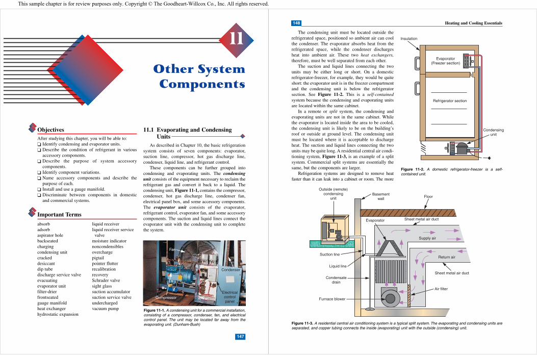
These components can be further grouped intocondensing and evaporating units. The condensingunit consists of the equipment necessary to reclaim therefrigerant gas and convert it back to a liquid. Thecondensing unit, Figure 11-1, contains the compressor,condenser, hot gas discharge line, condenser fan,electrical panel box, and some accessory components.The evaporator unit consists of the evaporator,refrigerant control, evaporator fan, and some accessorycomponents. The suction and liquid lines connect theevaporator unit with the condensing unit to completethe system.
absorbadsorbaspirator holebackseatedchargingcondensing unitcrackeddesiccantdip tubedischarge service valveevacuatingevaporator unitfilter-drierfrontseatedgauge manifoldheat exchangerhydrostatic expansion
liquid receiverliquid receiver service
valvemoisture indicatornoncondensiblesoverchargepigtailpointer flutterrecalibrationrecoverySchrader valvesight glasssuction accumulatorsuction service valveunderchargedvacuum pump
Other SystemComponents
11
147
Fan
Compressor
Condenser
Electricalcontrolpanel
Figure 11-1. A condensing unit for a commercial installation,consisting of a compressor, condenser, fan, and electricalcontrol panel. The unit may be located far away from theevaporating unit. (Dunham-Bush)
148 Heating and Cooling Essentials
The condensing unit must be located outside therefrigerated space, positioned so ambient air can coolthe condenser. The evaporator absorbs heat from therefrigerated space, while the condenser dischargesheat into ambient air. These two heat exchangers,therefore, must be well separated from each other.
The suction and liquid lines connecting the twounits may be either long or short. On a domesticrefrigerator-freezer, for example, they would be quiteshort: the evaporator unit is in the freezer compartmentand the condensing unit is below the refrigeratorsection. See Figure 11-2. This is a self-containedsystem because the condensing and evaporating unitsare located within the same cabinet.
In a remote or split system, the condensing andevaporating units are not in the same cabinet. Whilethe evaporator is located inside the area to be cooled,the condensing unit is likely to be on the building’sroof or outside at ground level. The condensing unitmust be located where it is acceptable to dischargeheat. The suction and liquid lines connecting the twounits may be quite long. A residential central air condi-tioning system, Figure 11-3, is an example of a splitsystem. Commercial split systems are essentially thesame, but the components are larger.
Refrigeration systems are designed to remove heatfaster than it can leak into a cabinet or room. The more
Figure 11-2. A domestic refrigerator-freezer is a self-contained unit.
Basementwall Floor
Sheet metal air duct
Supply air
Outside (remote)condensing
unit
Suction line
Liquid line
Condensatedrain
Furnace blower
Air filter
Sheet metal air duct
Return air
Evaporator
Figure 11-3. A residential central air conditioning system is a typical split system. The evaporating and condensing units areseparated, and copper tubing connects the inside (evaporating) unit with the outside (condensing) unit.
This sample chapter is for review purposes only. Copyright © The Goodheart-Willcox Co., Inc. All rights reserved.

149Chapter 11 Other System Components
heat leakage, or load, the bigger the system must be. Otherthan size, all systems are fundamentally the same. Thosethat appear more complicated simply have additionalcomponents to make them more efficient and serviceable.
11.2 Other System ComponentsTo understand the operation of any system, you
need to know how individual components work andaffect the system. A malfunction by one componentwill impact the operation of other components.Different components, or combinations of components,make the system more efficient, versatile, andserviceable. For example, many accessory componentsfacilitate checking system operation and performing
repairs. Some components keep the system clean.Others provide a means for isolating sections forrepairs. It is important to understand the purpose,theory, and operation of these components. Being ableto identify them and understand their functions willhelp you troubleshoot and service a system.
11.2.1 Liquid ReceiverThe liquid receiver is an important accessory in large
systems. It is installed in the liquid line and serves as astorage tank for excess liquid refrigerant. SeeFigure 11-4. Ideally, the refrigerant should boil off insidethe evaporator at the same rate it is being changed to aliquid state in the condenser. Such a balance is generallyachieved in domestic systems, which operate at a fairly
Evaporator
Service valve
Liquid line
Dip tubeReceiver
Outlet
Inlet
Condenser
Outlet
Service valve
Inlet
Dip tube
Liquid
Filterscreen
Figure 11-4. Liquid receivers act as reservoirs for excess liquid refrigerant in large systems. Receivers are located in the liquidline. Both horizontal and vertical types are used, depending upon the application. A—Horizontal receiver. B—Vertical receiver.
A
B
150 Heating and Cooling Essentials
steady rate. Larger commercial systems, however,require varying amounts of refrigerant at different times,depending upon the heat load on the evaporator.Therefore, a reserve of refrigerant must be available.
Liquid receivers are not used in domestic refriger-ation systems. The cost is prohibitive, and domesticsystems use a capillary tube for the refrigerant control. The amount of refrigerant in domestic systemsis critical. Because excess refrigerant accumulatesin the condenser and reduces its capacity, even aone-half-ounce overcharge (excess of refrigerant) willcause high head pressure.
Commercial systems normally use a thermostaticexpansion valve for the refrigerant control, whichpermits the use of a liquid receiver. (Refrigerantcontrols are fully explained in Chapter 16.)Commercial systems allow for some excessrefrigerant; the liquid receiver acts as a storage placefor the excess. The amount of refrigerant in acommercial system is not critical unless it isundercharged (has insufficient refrigerant).
Commercial systems require large quantities ofrefrigerant to operate, so the liquid receiver must be largeenough to hold all the refrigerant in the system plus any
excess. All refrigerants are expensive, and the ability ofthe receiver to hold the entire refrigerant charge is verydesirable when the system must be opened for repairs.
The liquid receiver should be no more than 80% fullwhen holding the entire system charge. Since all liquidsexpand (occupy more space) when heated, the extra20% capacity allows for liquid expansion within thereceiver. The principle is called hydrostatic expansion.
The liquid receiver is usually located close to (orbelow) the condenser. Liquid from the condenser dripsinto the receiver inlet. As shown in Figure 11-4, thereceiver outlet contains a dip tube that extends toabout one-half inch from the bottom of the receiver.The dip tube ensures that only liquid (no vapor) entersthe liquid line at the receiver outlet.
Some large receivers are equipped with two servicevalves, one at the inlet and one at the outlet. Thesereceivers, Figure 11-5, also contain a fusible plug orpressure relief valve as a safety device. The plug orvalve relieves any sudden increase in pressure to anunsafe level. Such an increase might occur in a fire, forexample. The spring-loaded pressure relief valve,Figure 11-6, opens automatically when a specifiedpressure is reached in the receiver. The pressure atwhich the valve opens is adjustable within a givenrange. The fusible plug, Figure 11-7, is a relief devicedesigned to melt at a specified temperature. It releasesthe refrigerant if an unsafe temperature (and corre-sponding unsafe pressure) is reached.
Liquid in
Fusible plug
Liquid out
Liquid in Opening for fusibleplug or relief valve
Liquid out
A
B
Figure 11-5. Large liquid receivers with pressure-reliefdevices. A—Vertical receiver with fusible plug installed.B—Horizontal receiver with provision for either fusible plugor relief valve. (Standard Refrigeration Company)
Lead andwire seal
Figure 11-6. The spring-pressure relief valve opens at aspecified pressure, then closes again when pressure dropsbelow that level. The pressure at which the valve opens isadjustable within a given range. The lead and wire sealprevents tampering with the valve pressure setting.(Standard Refrigeration Company)
Solder
Figure 11-7. A fusible plug has an opening sealed withsolder that melts at a specified temperature, usually 165°Fto 210°F (74°C to 99°C).

151Chapter 11 Other System Components
Some very large receivers are equipped with adial-type gauge or a liquid level sight glass to indicatehow much liquid refrigerant is in the receiver. Asnoted, liquid level in the receiver should never be morethan 80% of its capacity when holding the entirecharge of the system.
11.2.2 Service ValvesA service valve is an accessory that serves no
operating function but is indispensable when workmust be performed on the system. Service valves areprovided on commercial systems for troubleshootingand making repairs. They are not factory-installed on
domestic systems but often are installed by technicianswhen servicing is needed. The valves make it possibleto block off certain sections of the system for servicingor for reading operating pressures using the gaugemanifold. The gauge manifold is a pressure-checkingdevice that has compound and high-pressure gauges,control valves, and hose connectors from the servicevalves. The service technician must fully understandwhere service valves are located and how they operate.
Service valve locationsService valves on commercial systems are normally
placed in three strategic locations, Figure 11-8. The
Figure 11-8. Service valves are normally located at three specific places. These locations permit easy access to the systemfor servicing.
152 Heating and Cooling Essentials
valves provide access for pressure readings, and can beused to control system operation and isolate sections todiagnose problems. Failure to use these valves properlymay result in wrong diagnoses, excessive service time,and unnecessary loss of refrigerant.
Suction service valve. The suction service valve(SSV) is located on the low-pressure side of thesystem between the compressor and the suction line.Usually, the valve is bolted to the compressor, and thesuction line is connected to the valve. The locationpermits the technician to:� Read the system’s low-side pressure while the
compressor is running.� Restrict the flow of refrigerant entering the
compressor.� Completely stop the refrigerant from entering the
compressor.Discharge service valve. The discharge service
valve (DSV) is located on the high-pressure side of thesystem. Normally, the valve is bolted to the compressor,and the hot gas discharge line is connected to the valve.The location permits the technician to:� Read the system’s high-side pressure while the
compressor is running.� Restrict the flow of gas leaving the compressor.� Completely stop the gas from leaving the
compressor.WARNING: Never frontseat (close) this valve
while the compressor is running. Discharge pressurewill rapidly reach extremely high, unsafe levels.
By placing a service valve on each side of thecompressor, it is possible to obtain high- and low-sidepressure readings at a single location, the compressor.The valve arrangement makes it possible tocompletely isolate, or block off, the compressor (whenit is not running) from the rest of the system.
Liquid receiver service valve. The liquid receiverservice valve (LRSV) is located in the liquid line,at the liquid receiver outlet. The LRSV is weldedto the liquid receiver, and the liquid line isconnected to the valve. The location permits thetechnician to:� Read the system’s high-side pressure while the
compressor is running.� Restrict the flow of refrigerant leaving the receiver.� Completely stop the liquid refrigerant from
leaving the receiver (while the compressor isrunning).
Some large commercial systems include anotherservice valve located at the liquid receiver inlet. Thisprovides a method to isolate the receiver from the restof the system by closing (frontseating) both receivervalves. Closing both valves traps most of therefrigerant inside the liquid receiver.
Service valve ratchet wrenchesService valves vary in size along with the size of
the system. Valve stem sizes vary as well, requiringservice valve wrenches of different sizes. Theratchet-type wrench with four sizes of openings,Figure 11-9, is the most popular; it fits most valvestems and is easily reversed. This tool is a must inevery technician’s tool kit.
Service valve operationAll service valves are designed to function in the
same manner, regardless of location, size, or shape.While all service valves have three openings, only twoare controlled by the valve stem. The opening to thecompressor (or receiver) is always open. The valvestem controls the inlet (or outlet) and the service port.See Figure 11-10.
Suction service valve (backseated). With thevalve stem in the backseated position, Figure 11-11,the flow of refrigerant from the suction line to thecompressor is unrestricted. However, the servicegauge port is blocked off (closed) — the normal posi-tion of the valve stem when the system is operating.
Suction service valve (cracked). To obtain apressure reading at the suction service valve, the valvestem must first be in the backseated position to close offthe gauge port. Then, you can remove the cap from the
Figure 11-9. The most popular type of service valve wrenchis a ratchet-type. It has four sizes of openings and is easilyreversed. (Robinair Mfg. Corp.)
Figure 11-10. Service valves have three openings: the inletor outlet (where the refrigerant enters or leaves the valve),the opening to the compressor or liquid receiver, andthe service port opening. The valve stem is able to closeeither the inlet/outlet or the service port, but not the third(compressor) opening.

153Chapter 11 Other System Components
gauge port and connect the blue hose from the compoundgauge on the gauge manifold. Next, the service valvestem is cracked (opened by turning the stem about one ortwo turns to the right). See Figure 11-12. This opens thegauge port, and the compound gauge immediatelyregisters the pressure reading.
“Cracking the valve” does not restrict the flow ofrefrigerant to the compressor. The procedure permitsyou to read the low-side pressure while the system isoperating.
Suction service valve (frontseated). When theSSV is frontseated (valve stem screwed all the wayto the right), the inlet opening is closed off. SeeFigure 11-13. This frontseated position preventsrefrigerant gas from entering the valve. However, thegauge port is open to the compressor. Remember thatthe compressor opening cannot be closed by the valvestem. The valve stem controls only the gas inlet andthe gauge port opening.
If the SSV is frontseated while the compressor isrunning, the compressor will immediately show agood vacuum on the compound gauge because thesuction gas cannot enter the compressor. This proce-dure is used to check the operation of the compressor.Failure of the compressor to pull a good vacuum whenthe SSV is frontseated indicates a problem with thecompressor valve reeds. CAUTION: When the servicevalve port is open, avoid allowing the compressor todraw moisture-laden atmospheric air into the system.
Figure 11-11. Suction service valve with stem in the back-seated position. This is the normal operating position of thevalve stem.
Figure 11-12. The suction service valve with the stem in the “cracked” position permits the technician to read thelow-side pressure while the system is in operation.
154 Heating and Cooling Essentials
Service valves on small commercial units have abuilt-in 1/4″ (6.4 mm) male flare fitting at the gauge port(as previously illustrated) for attaching a hose from thegauge manifold. Larger service valves may have one ortwo openings at the gauge port, plugged with a 1/8″ (3.1mm) male pipe plug. To attach the gauge hose to theservice valve, remove the plug and install a 1/8″ (3.1 mm)MPT × 1/4″ (6.4 mm) MFT half-union, as shownin Figure 11-14. All technicians keep half-unions readilyavailable.
Discharge service valve operationJust like the suction service valve, the discharge
service valve has three openings and three possiblevalve stem positions. See Figure 11-15. However,the DSV controls high-pressure gas leaving thecompressor rather than low-pressure gas enteringthe compressor. The opening from the compressorcannot be closed. The gauge port opening isavailable for the technician to install the red hosefrom the high-pressure gauge, making it possible toobtain a discharge pressure reading while the system isrunning.
The valve is backseated for normal operation andwhen connecting the red hose from the gaugemanifold. After connecting the red hose, the valveis cracked open and the discharge pressure isimmediately revealed on the high-pressure gauge.
The discharge service valve should never befrontseated (screwed all the way in) when thecompressor is running because it will close the hot gas
Figure 11-13. The suction service valve with the stem in the frontseated position permits the technician to take a compressorvacuum reading. The inlet is closed, so no refrigerant gas can reach the compressor.
Installhalf-union
Hoseconnection
Removepipe plug
Flare-typeservice valve
Service ports(1/8" pipe plug)
Flange-typeservice valve
Figure 11-14. Replacing pipe plugs on valves with half-unions.

discharge line. The high-pressure gas cannot escape,so very high pressure will develop rapidly in theservice valve. This extreme pressure may blow thehose off the valve or cause the compressor to shut offon a safety control.
If the compressor is shut off for replacement, boththe discharge service valve and the suction servicevalve are frontseated to isolate the compressor fromthe system. Both service valves are unbolted from thecompressor, the old compressor is removed, and theservice valves are rebolted to the new compressor afterit is installed. The procedure saves the refrigerant inthe system, except for a small amount of gas trappedinside the old compressor.
Gaskets are provided with each new compressor foruse between the compressor body and the service valves.Old gaskets should be removed with a pocketknife andthe mating surfaces cleaned. Be careful not to scratch orcut the mating surfaces. Coat the new gaskets withrefrigeration oil before installing them. The oil expandsthe gaskets slightly so they can be squeezed between themating surfaces for a leakproof fit.
Liquid receiver service valveThe liquid receiver service valve is welded or
screwed into the receiver outlet, and the liquid line isconnected to it with a flare nut. This service valveoperates just like the suction and discharge valves,except it controls the liquid leaving the receiver. Asshown in Figure 11-16, the valve is backseated duringnormal operation. The valve can be cracked to readhigh-side pressures at the receiver valve or frontseatedto completely stop liquid refrigerant from leaving thereceiver.
Pumping down the system. The technician oftenhas to manually “pump down the system,” meaningremove all refrigerant from the low-pressure side andpump it over to the high-pressure side of the system.Pumping down is accomplished by frontseating theliquid receiver service valve while the system isrunning. The compressor removes refrigerant fromthe low-pressure side of the system all the way back tothe valve. The compressor is then turned off. Thevalve reeds inside the compressor head shouldprevent refrigerant gas from flowing back into the
155Chapter 11 Other System Components
Figure 11-15. The discharge service valve with the valve stem in the cracked position permits the technician to read thedischarge (high-side) pressure while the system is in operation.
156 Heating and Cooling Essentials
low-pressure side of the system. If necessary, thesuction service valve can be frontseated after thesystem is pumped down.
Whenever a system is pumped down, its low-pressure side is usually in a good vacuum. The systemshould not be opened while in a vacuum becausemoisture-laden atmospheric air will rush in. A vacuumpump would be needed to remove the unwanted gases.
Liquid receiver with two service valves. Largeliquid receivers sometimes have two service valves,one at the inlet and one at the outlet of the receiver,Figure 11-17. Two valves make it possible to pumpdown the system, then frontseat both receiver valves.The procedure isolates the liquid receiver, whichcontains most of the refrigerant in the system (somegas remains in the condenser and the hot gas dischargeline). The procedure would be used to make repairs tothe condenser, for example. Pumping down the systemsaves most of the refrigerant.
The service valve on the inlet to the receiver alsomakes it easy to purge air from the receiver. Wheneveratmospheric air enters the system, it becomes trappedin the liquid receiver. Atmospheric air is considerednoncondensible and remains a gas as it travels throughthe condenser. Therefore, it becomes trapped in the topof the liquid receiver.
The technician can remove noncondensibles byturning the system off and frontseating the receiver inletvalve. This blocks off the valve inlet and opens theservice port to the top of the receiver. The noncondensi-bles now can be removed through the service port. Theprocedure requires the use of a refrigerant recoverydevice until all noncondensibles are removed from thereceiver, and the head pressure returns to normal.
Backseatedposition
Outlet(to evaporator)
Gaugehose
Diptube
Filter
Frontseated(pumpdown)
Outlet Inlet
Figure 11-16. Liquid receiver service valve. A—The valve isbackseated for normal operation. B—The valve isfrontseated to pump down the system.
A
B
Both valvesfrontseated
Outlet Inlet
Figure 11-17. Service valves at both the inlet and outlet ofthe liquid receiver allow isolation of the receiver. Most of thesystem’s refrigerant, in liquid form, can be trapped there.Noncondensibles can be purged through the service port ofthe inlet valve.

157Chapter 11 Other System Components
Service valves for domestic systemsManufacturers of domestic systems, such as refrig-
erators and freezers, seldom have factory-installedservice valves. These systems are totally hermetic(sealed systems); the service technician must installservice valves as needed. There are two basic types ofvalves installed by technicians: clamp-on valves andcore-type valves.
Clamp-on valves. These valves are known byvarious names, (including saddle valve and line-piercing valve), but all are used in the same way: theystraddle the tubing and clamp into place, then use adepressor pin to puncture a hole in the tubing. SeeFigure 11-18. Gaskets and seals inside the valveprevent refrigerant from leaking around the puncturedhole. The valve provides an access port for attaching ahose from the gauge manifold.
Once these clamp-on valves are installed on thesuction or hot gas discharge lines, they become apermanent addition to the system. They also become asource of future problems due to possible leakage atthe hole. Clamp-on valves should only be used fortroubleshooting one of two problems:� The compressor runs but does not compress properly.� The system is entirely out of refrigerant due to a leak.
The pressures indicated on the gauge manifold willreveal which of the two problems exists. If the gaugesreveal the same pressure on each side of the system, thecompressor is defective (has bad valve reeds) and must bereplaced. If the gauges reveal no pressure on either side ofthe system, the unit has a leak and has lost all refrigerant.
Both problems involve expensive repairs thatrequire breaking into the hermetic system. The tube-piercing saddle valves are used for diagnosis only andshould be replaced by Schrader (core-type) valves ifrepairs are authorized.
Schrader (core-type) valves. The recommendedmethod for breaking into and resealing a hermeticsystem is to install a Schrader valve. See Figure 11-19.Most hermetic compressors are factory-equipped withan extra copper tube (a pigtail) that allows access to thesuction pressure inside the hermetic shell. A Schradervalve is easily brazed to the end of the pigtail.
Access to the high-pressure side is usually difficultbecause the hot gas discharge line must be cut and awrought copper tee installed to provide an opening forinstalling a valve. The valve is brazed to the branchopening on the tee.
Schrader valves have cores similar to those onautomobile tires. Because of the special gaskets used,the valve core must be removed before brazing. It canbe replaced after the joint has cooled. The hoses on thegauge manifold have a built-in device to depress thecore when the hose is connected to the valve.
The seal cap for a core valve contains a rubbergasket to help prevent leaks. The cap should always beinstalled when the valve is not in use.
11.3 The Gauge ManifoldThe gauge manifold is the technician’s most
valuable tool. It is used to determine the operatingcharacteristics inside the system. The gauge manifold,
Sealcap
Depressorpin
Serviceaccess
port
Sealcap
Tubing sizeadapters
Serviceaccess
port
A B
Figure 11-18. Saddle valves. A—The valve is clamped over the tubing to provide an access port for diagnosing system prob-lems. Adapters permit use on different tubing sizes. B—The depressor pin punctures the tubing when the cap is tightened.Then, the pin is removed, and the cap seals the access port.
158 Heating and Cooling Essentials
as noted earlier in this chapter, is a pressure-checkingdevice with both compound and high-pressure gauges.See Figure 11-20. It also has control valves andconnectors for hoses to the service valves. The gaugesreveal the system’s operating pressures which, in turn,help the technician determine the needed repairs. Themanifold is also used while performing the repairs.
Learning how to use the gauge manifold properly willsave countless hours diagnosing field problems, deter-mining their causes, and deciding their solutions. Withoutth if ld it i i ibl t id tif t
11.3.1 Pressure GaugesThe gauge manifold has two gauges for a wide
range of readings. See Figure 11-21. The compoundgauge (blue) is designed for connection to the low-pressure side of the refrigeration system. It has scalesto show pressure readings from 0 psig to above120 psig (828 kPa), and vacuum from 0 in. Hg to 30in. Hg. The high-pressure gauge (red) is designed forconnection to the high-pressure side of the refrigera-tion system; it typically shows only pressure readings(0 psig to 500 psig or 0 kPa to 3450 kPa).
The rapid compression strokes of the compressorpistons sometimes create pressure pulsations thatcause the gauge pointer to swing above and below theactual pressure reading. Called pointer flutter, it doesnot indicate problems with the compressor or anyother type of defect. The correct pressure reading isobtained at the center of the flutter. Special pressuregauges, Figure 11-22, are available with a built-inpulsation dampener to prevent pointer flutter.
The saturation temperature-pressure relationshipfor one or more refrigerants is included on the dial faceof refrigeration gauges. The outside scale on the dialface (black numbers) indicates gauge pressure (psig).The three inner scales (red numbers) indicateFahrenheit saturation temperatures that correspondwith the pressure for each of the three refrigerants.To read the scales properly, simply follow the lineof the needle to the proper temperature scale todetermine the temperature that corresponds with thepressure reading.
Compoundgauge
Controlvalve
Manifold
Heavy-dutyhoses
Controlvalve
Flare fittings
High-pressuregauge
Hanging hook
Figure 11-20. The gauge manifold is the technician’s basic toolfor determining system pressures. It is equipped with two gauges,two control valves, and three connection hoses. (Uniweld)
Seal cap
Valvecores
Valvebodies
Coppertubing
Pigtail
Tee
Brazing type Screw type
Figure 11-19. Schrader valves are installed for permanentservice access to domestic systems. A—Brazing-type andscrew-type Schrader valves. (J.B. Industries) B—Becauseheat will affect the gasket material, the cores must beremoved while the valve body is being brazed to the tubing.
A
B

159Chapter 11 Other System Components
R-22, and R-502. The scales are a convenience and donot affect the gauge pressure readings. Consult a satu-ration temperature-pressure card for other refrigerants.
Remember that refrigeration gauges only revealsaturation temperature for a given pressure. Thegauges do not reveal superheat (temperature abovesaturation) or subcooling (temperature belowsaturation). Because the gauges only read saturation, athermometer is used to determine if the actual
temperature is above or below the saturation point(superheat or subcooling).
For efficient operation of the system, the amount ofsuperheat or subcooling at various points must bedetermined and controlled. For example, a pressurereading at the suction service valve for R-134a may be12 psig (83 kPa), which corresponds to 10°F (–12°C)saturation temperature. However, if a thermometer isclamped to the suction line at the inlet to the suctionservice valve, the reading would be about 25°F (–4°C).The difference in temperature readings amounts to15 degrees Fahrenheit (25 – 10 = 15) or 8 degreesCelsius. Therefore, the refrigerant vapor contains 15degrees Fahrenheit (8 degrees Celsius) of superheat asit enters the suction service valve.
Recalibrating gaugesRefrigeration gauges are sensitive instruments,
initially calibrated to produce accurate readings. Whilethese gauges can withstand some abuse, they shouldbe handled with care. It is not unusual for the gaugesto require recalibration in the field because of useand handling.
To gain access to the recalibration screw, theclear crystal face on the gauge must be unscrewed,Figure 11-23. The recalibration screw is located onthe gauge face, just below the needle hub. The hose onthe manifold body immediately beneath the gauge isremoved to expose the inlet port to atmosphericpressure. A suitable screwdriver is used to slowly turnthe recalibration screw until the pointer lines up withzero (atmospheric).
11.3.2 Manifold BodyThe compound gauge and the high-pressure gauge
are directly connected to the hoses by special bypassgas passages through the manifold body. A hoseconnection is located directly beneath each gauge. Thegas passage between each gauge and its connectinghose is never closed. See Figure 11-24. The two hand
Manifold
Compoundgauge
High-pressuregauge
Figure 11-21. The compound gauge is used for both pres-sure and vacuum readings, while the high-pressure gauge isused only for pressure readings. (TIF Instruments, Inc.)
Pulsation-dampening gauge Ordinary gauge
Figure 11-22. A special gauge with a pulsation dampenereliminates pointer flutter, making more accurate readingspossible. (Uniweld)
Figure 11-23. Unscrew the clear crystal of the gauge toreach the recalibration screw on the dial face. For accuratereadings, gauges must be recalibrated, or zeroed, periodi-cally. (Imperial Eastman)
160 Heating and Cooling Essentials
valves located at each end of the manifold controlaccess to the center hose only. These valves do notcontrol the bypass gas passages to the gauges.
The center hose is for adding refrigerant to a system(charging), removing refrigerant from a system(recovery), or emptying a system with a vacuum pump(evacuating). Each of these procedures requires thehand valves be opened properly to gain access to thecenter hose. Both valves are normally closed and shouldbe opened only when access to the center hose isneeded. The left-hand valve controls access to the centerhose via the low-pressure side and the right-hand valvevia the high-pressure side. Opening both hand valvesopens the center hose to both gauges.
11.3.3 Refrigeration HosesRefrigeration hoses are designed to withstand
working pressures of 500 psig to 750 psig (3450 kPato 5175 kPa). The hoses are normally color-coded:blue for low pressure, red for high pressure, andyellow for the center connection. The hoses are alsodesigned to remain flexible under most temperatureconditions for easy handling. Each hose has astraight connector at one end and an angled (45°)connector at the other, Figure 11-25. The straight endsconnect to the 1/4″ flare fittings on the manifold body.The angled ends easily connect to the proper servicevalve by finger-tightening. Angled ends contain a
valve-core depressor for connection to Schrader(core-type) valves.
A special gasket inside the angled hose endprovides a leakproof seal on the service valve orSchrader valve. The gasket can become badly worndue to long use or abuse, but it is easily replaced.Replacement gaskets are available from your localsupplier. Before fully hand-tightening refrigeranthoses, purge them of air by allowing a tiny amount ofrefrigerant to escape through them.
11.4 Purging and Venting
“Purging” and “venting” are terms that describetwo repair procedures involving the release of refrig-erant to the atmosphere.
Purging describes the necessary process of releasinga small quantity of refrigerant from the hose ends afterconnection to a system. Purging removes atmosphericmoisture and air from the service hoses, thus preventingcontamination of the system. Small releases ofrefrigerant due to purging, connecting, or disconnectinghoses is not prohibited by the Clean Air Act.
Some service procedures require the removal of all
pressure (refrigerant) from the system prior toperforming repairs. Older service procedures simplyremoved the pressure by venting (releasing) the systemrefrigerant to the atmosphere. Because of ozonedepletion, the deliberate release of refrigerant to theatmosphere is prohibited by federal law. New recoveryequipment and procedures for saving the refrigerantfor reuse are described in Chapter 13.
11.4.1 Evacuating the System“Evacuation” means to clean a system with a vacuum
pump to remove all gas and moisture. Evacuation is donebefore charging a system with refrigerant. Figure 11-26shows the arrangement for evacuating a system.
The yellow hose is connected to a two-stage
Compoundgauge
High-pressuregaugeOverpressure
warningzone
Recalibrationscrew
Replaceablevalve seals
Low-pressurehose connection
High-pressurehose connection
Low-pressurehose connection
Center (charging)hose connection
Figure 11-24. Cross section of the gauge manifold body.The hand valves are used only for access to the centerhose. (Uniweld)
Charging hose assembly(angled end)
Adjustablebrass coredepressor
Figure 11-25. A refrigeration hose is designed to withstandhigh pressures and temperature extremes. The straightconnector attaches to the manifold body; the angledconnector attaches to the service valve or Schrader valve.

161Chapter 11 Other System Components
vacuum pump. The vacuum pump removes moisturefrom the system by reducing pressure so the moistureboils (vaporizes) at normal atmospheric temperatures.In a perfect vacuum, water changes state from liquid tovapor at –90°F (–68°C). Moisture is removed from thesystem as a vapor by the vacuum pump.
Reducing pressure too quickly will cause the water
to boil rapidly and the remaining water to freeze.Water expands when it freezes, and expansion couldcause tubing to burst or leak. Excess moisture shouldbe removed before evacuation by blowing the systemout with nitrogen at 150 psig to 300 psig (1035 kPa to2070 kPa).
Two-stage vacuum pumps, Figure 11-27, are
Two-stagevacuum pump
Water vapor(moisture from
the system)
Open Open
Figure 11-26. Typical arrangement for evacuating a refrigeration system. The two-stage vacuum pump reduces system pres-sure low enough to vaporize any moisture and withdraw the vapor from the system.
162 Heating and Cooling Essentials
necessary to reduce the pressure sufficiently and holdit at a reduced level long enough for the moisture tovaporize and be removed. A second pumping chamberenables the pump to obtain a lower vacuum. In a two-stage pump, the exhaust of the first pumping stage isdischarged into the intake of the second pumpingstage, rather than to the atmosphere. The second stagepumps at a lower pressure and pulls a deeper vacuumon the system than the first stage could by itself. Two-stage vacuum pumps are capable of pulling down to anextremely low vacuum, but a vacuum seldom goesbelow 500μ (microns) under field conditions. Thetwo-stage vacuum pumps are able to reach and hold alow vacuum for prolonged periods of time.
Figure 11-28 provides conversion factors for
evacuating or dehydrating a system with avacuum pump.
Evacuation procedure1. Connect the red and blue hoses on the gauge
manifold to the appropriate service valves. Crackopen the service valves, and close the manifoldhand valves.
2. Connect the center (yellow) hose to a two-stagevacuum pump, and start the pump. Very slowlycrack open both manifold hand valves. Be careful toavoid drawing oil out with the vacuum pump. Afterone or two minutes, the compound gauge shouldread 15 in. Hg (15 inches vacuum). Then, bothmanifold valves can be fully opened. The vacuumpump should quickly reduce the system pressure toabout 29 or 30 in. Hg. If the pump fails to pull anadequate vacuum, there is probably a leak in thesystem that must be found and corrected. Afterreaching a vacuum of 29 or 30 in. Hg, permit thevacuum pump to operate for at least one-half hour.Adequate time is needed for all moisture to vaporizeand all refrigerant gas mixed with oil in thecompressor crankcase to be evacuated. Largesystems require more time on the vacuum pump.
3. Before shutting off the vacuum pump, close bothmanifold hand valves. Shut down the pump, andremove the yellow hose. At this point, all gases havebeen removed by the vacuum pump, and the refrig-eration system is in a deep vacuum. The systemshould hold this vacuum, unless a leak permitsatmospheric air to enter (or the vacuum pump hasnot been connected to the system long enough).
Leak detection. Closing the manifold valvesand waiting to see if the system loses its vacuum is nota proper leak-detection method. The vacuum pumpmay have been stopped too early for properevacuation, or the leak may be too small foratmospheric air to enter. Even with a perfect vacuum,the pressure differential between the inside andoutside of the tubing is only 15 psi (103 kPa). It is poorprocedure to leak test with such a low pressure differ-ential. Most leak detection is accomplished withpressures of 200 psi to 300 psi (1380 kPa to 2070 kPa)because the refrigerant molecules are much smallerthan air molecules. Various leak detection methods arediscussed in Chapter 15.
11.4.2 Charging the SystemDuring compressor operation, the pressure in the
high-pressure side of the system is higher than thepressure in the refrigerant cylinder. If the manifoldhand valve on the right side (high-pressure) is acci-
Figure 11-27. Two-stage vacuum pumps are available indifferent sizes for varying applications. A—Small 1.6 cfmpump. (Thermal Engineering) B—Cart-mounted 15 cfm unitfor use on large systems. (Robinair Mfg. Corp.)
A
B

163Chapter 11 Other System Components
dentally opened, refrigerant will be pumped back intothe cylinder. This could cause dangerous overpressurein the cylinder and rupture it. Always feed the refrig-erant charge into the low-pressure side of the system,and always feed refrigerant as a gas, not a liquid.
The gauge manifold arrangement for charging asystem is shown in Figure 11-29. Charging is donewith the system operating. Follow this procedure:
1. Close both manifold hand valves. Check gaugepointers for accuracy of zero readings. Recalibrateif necessary.
2. Connect the low-pressure (blue) compound gaugehose to the suction service valve. Finger-tighten it.Crack open the service valve.
3. Connect the high-pressure (red) gauge hose to thedischarge service valve; finger-tighten it. Crackopen the service valve. (Remember the high-pressure manifold hand valve must remain closed.)
4. Connect the center (yellow) charging hose to therefrigerant cylinder. Make sure the container is in anupright position so you obtain gas, not liquid. Nevercharge liquid refrigerant into a system; it will damagecompressor valve reeds or remove oil from bearings.
5. Fully open the valve on the refrigerant cylinder totransfer control to the gauge manifold.
6. With the system running, slowly open the left side(low-pressure) manifold hand valve. The pressureinside the refrigerant cylinder is higher than thelow-side system pressure, so the gaseous refrig-erant will be forced up through the center hose,through the left side of the manifold, into the bluehose, and into the system. The manifold valve onthe right side (high-pressure) must remain closedduring the charging procedure.
7. To observe the changing conditions of the low-side system pressure, occasionally close the left-side manifold valve, and check the compoundgauge. Also, closely watch the high-pressuregauge during charging. Continue adding refrig-erant to the system until both high and low pres-sures achieve normal status.
8. Backseat (close) both service valves, and close thevalve on the refrigerant cylinder. Disconnect thehoses from the service valves, and screw the hoseends onto the “dummy” fittings at the manifold.Replace covers or caps on the service valves.
Pounds Per BoilingInches of Square Inch Millimeters TemperatureMercury Absolute of Mercury Microns of Water
( Hg) (psia) (mm Hg) (˚F/˚C)
0 14.696 760 760,000 212/100
10.24 9.629 500 500,000 192/89
22.05 3.865 200 200,000 151/66
25.98 1.935 100 100,000 124/51
27.95 0.968 50 50,000 101/38
28.94 0.481 25 25,000 78/26
29.53 0.192 10 10,000 52/11
29.67 0.122 6.3 6,300 40/4
29.72 0.099 5 5,000 35/2
29.842 0.039 2 2,000 15/–9
29.882 0.019 1.0 1,000 +1/–17
29.901 0.010 0.5 500 –11/–24
29.917 0.002 0.1 100 –38/–39
29.919 0.001 0.05 50 –50/–46
29.920 0.0002 0.01 10 –70/–57
29.921 0.0000 0 0 –90/–68
One Atmosphere = 14.696 psia (atmospheric pressure at sea leve)= 760 mm Hg absolute pressure at 32˚F (0˚C)= 29.921 in. Hg absolute at 32˚F (0˚C)
Conversion Factors
Figure 11-28. Conversion factors for using a vacuum pump to evacuate or dehydrate a system.
164 Heating and Cooling Essentials
100 psig (690 kPa) 120 psig (828 kPa)
High-pressure-sidehand valve closed
Low-pressure-sidehand valve open
Suction line(20 psig or138 kPa)
Cracked
Cylindervalve open
Vapor(100 psig or
690 kPa)
Figure 11-29. Typical arrangement for charging a refrigeration system. The refrigerant cylinder pressure must be greater thanthe pressure in the suction line so the refrigerant is forced into the system.

165Chapter 11 Other System Components
11.5 Filter-driersRegardless of the care used in evacuating and
charging a system, it is safe to assume the system isnot completely free of moisture. A filter-drierinstalled in the system, Figure 11-30, will absorb theremaining moisture. It will also catch foreign particlescirculating with the refrigerant.
On commercial systems, the filter-drier is normallyinstalled in the liquid line, immediately after the liquidreceiver. A second unit may be installed in the suctionline as well, Figure 11-31. On domestic systems, thefilter-drier is typically located at the condenser outlet.
11.5.1 Moisture ProblemsWater or moisture is always present in refrigeration
systems and must be kept to an absolute minimum.Acceptable limits vary from one system to another andfrom one refrigerant to another. Moisture is theprimary factor in the formation of acids, sludge,copper plating, and corrosion. The service technicianshould always be alert to keep the moisture level of therefrigeration system as low as possible.
The main problems caused by moisture are:� Corrosion that damages metal parts and adds
contaminants to the system.� Formation of acid that damages the motor windings.
Since the motor windings are exposed to refrigerant,any acid that forms will cause a breakdown of theinsulation and result in a motor burnout.
� Freezing of moisture in the orifice of therefrigerant control valve or capillary tube. Frozenmoisture can block the flow of refrigerant and stopthe operation of the system.
Other sources of problems within the system are dirt,sludge, rust, and foreign matter such as flux, copper orbrass chips, and solder. These contaminants can damagepiston cylinder walls or compressor bearings, or mayplug capillary tubes and other refrigerant controls.
11.5.2 Filter-drier OperationFilter-driers in refrigeration systems work by
bringing liquid refrigerant in contact with a substancethat absorbs moisture in the refrigerant. The substanceis called a drying agent, or desiccant, and is usuallycapable of removing acid as well as moisture.
If properly sized, the filter-drier will not restrict theflow of refrigerant, even when the desiccant is full ofmoisture and no longer effective. Desiccants areextremely sensitive to moisture and must be protectedagainst it until ready for use. The factory seal on afilter-drier should not be removed until just beforeinstallation. Most filter-driers are direction-sensitive,meaning they must be oriented to the direction ofrefrigerant flow. Direction-sensitive filter-driers havean arrow printed on the body to indicate the properdirection of flow. See Figure 11-32.
Figure 11-30. Filter-driers remove residual moisture froma system and trap foreign particles circulating with therefrigerant. (Sporlan Valve Co.)
Figure 11-31. On commercial systems, the filter-drier isusually installed in the liquid line, just after the liquidreceiver. For additional protection, technicians sometimesinstall a second filter-drier, as shown, between thecompressor and evaporator.
166 Heating and Cooling Essentials
Desiccants used in filter-driers include activatedalumina, silica gel, and activated carbon, which absorb(soak up) moisture. They also include molecular sieves,which adsorb (collect substances on their surfaces in acondensed layer) contaminants from the refrigerationsystem. Desiccants are available in granular, bead, andblock forms, Figure 11-33. Combinations ofdesiccants can be used in solid cores and have certainadvantages over a single desiccant, such as absorptionof a greater variety of contaminants.
Do not attempt to reactivate a used filter-drier. Itshould be discarded when no longer effective. Themost common desiccants used today are activatedalumina and molecular sieve; occasionally silica gel isused. For desiccants to be returned to their activestates, they must be heated for four hours at tempera-tures ranging from 400°F to 600°F (204°C to 316°C).At these temperatures, all refrigeration oils decomposeinto sludges or acids. If a drier is reactivated after it
has been used, the oil will decompose into sludge andupon installation, will be released into the system. Thesludge could clog small ports, such as expansionvalves and capillary tubing.
On large commercial systems, a replaceableelement filter-drier is used. The filter-drier is boltedtogether, and replacement cores are available invacuum-packed metal containers. See Figure 11-34.
Special acid-removing filter-driers are available forfield installation in the suction line. Such filter-driersare used to clean the system and protect a newcompressor following a burnout.
Domestic filter-drierDomestic systems (refrigerators and freezers) also
have a filter-drier, but it is much smaller than those usedon commercial systems. The body of the domesticfilter-drier is made of copper and is brazed into thesystem at the outlet of the condenser, Figure 11-35.These filter-driers are normally direction-sensitive, butsome small-capacity units are nondirectional.
Filter
Moldeddesiccant
Figure 11-33. Desiccant granules can be molded into a corefor the receiver-drier, as shown in a cutaway view.(Sporlan Valve Co.)
Figure 11-32. This filter-drier is designed for attachment tothe liquid line with flare fittings. Other types are designed forbrazing into the line. Note the arrow indicating the properdirection of refrigerant flow through the device. To keep thedesiccant at full effectiveness, the seal caps on the fittingsshould be left in place until just before the filter-drier isinstalled. (Alco)
Filter
InletRetainingspring
Replaceablecores
Outlet
Figure 11-34. Replaceable element filter. A—A cutawayview shows the installation of two cores (elements) in thereceiver-drier shell. Access is by means of the bolted coverat the left. B—Replacement elements are packed in sealedcans that exclude moisture. Typical cores are shown.(Sporlan Valve Co.)
B
A

Domestic systems need a filter-drier to ensuretrouble-free operation. Due to the small amount ofrefrigerant circulating in the system, a single drop ofexcess moisture will cause a freeze-up. Thecomponents in the system are quite small; any foreignmaterial will cause severe problems. When a domestic(hermetic) system is opened for repairs, the filter-driershould always be replaced.
11.6 Sight GlassThe sight glass, Figure 11-36, is a small window
placed in the liquid line on commercial systems toprovide a view of the flowing liquid. The sight glassserves as a valuable service aid: visible bubbles indicateproblems within the system. Problems could be lowrefrigerant charge, low head pressure, insufficientsubcooling, restrictions, or poor piping design. Thesight glass is usually located close to the liquid receiverand immediately after the filter-drier, Figure 11-37.
The sight glass shows clear if the line is full ofliquid and shows bubbles if the system is having prob-lems. An occasional bubble is not unusual or harmful,but excessive bubbles indicate trouble in the system.
While the sight glass shows clear when full ofliquid, it also shows clear when empty. To determinethe correct situation, frontseat the liquid receiverservice valve, and pump down the system whilelooking through the sight glass. An empty systemshows no change. A full system, however, appears full,shows bubbles, and then appears empty.
167Chapter 11 Other System Components
Figure 11-35. Small filter-drier intended for a domestic unit.The copper tubes at each end are brazed into the system atthe condenser outlet. (Parker-Hannifin)
Clear viewingwindow
Flarefitting
Rubber O-ring
Figure 11-36. Typical sight glass. The clear window allowsthe technician to “look inside” the system and diagnoseproblems by the appearance of the refrigerant. Sight glassesare available with various types of fittings to suit differentsystem configurations. (Parker-Hannifin)
Figure 11-37. The sight glass is normally installed immediately after the filter-drier in the liquid line.
168 Heating and Cooling Essentials
11.6.1 Sight Glass with Moisture IndicatorMost sight glasses have a moisture indicator
centered within the viewing window, Figure 11-38.The indicator is highly sensitive to moisture, graduallychanging color to reflect the moisture content in therefrigerant. The indicator element is completelyreversible and changes color as often as the moisturecontent of the refrigerant varies.
Some change in color takes place rapidly at thestart-up of a new system or after the filter-drier isreplaced. The system should operate for about12 hours before you decide (based on the moistureindicator) that another filter-drier change is needed.Drying of the refrigerant should continue until theindicator element changes to the proper color.
All halogenated refrigerants (such as R-12, R-22,or R-502) accept very small amounts of moisture andstill function properly. However, when these levels areexceeded, severe problems develop. The amount ofmoisture in a refrigeration system must be kept to anabsolute minimum to provide trouble-free operation.Every precaution must be taken to prevent moisturefrom entering the system during installation or serviceoperations. Any moisture that does enter the systemshould be removed quickly.
A color reference code is printed around the edge ofthe sight glass or on the front of the sight glass body,Figure 11-39. One manufacturer’s color code variesfrom dark green (dry), to light green (caution), to brightyellow (very wet). Another manufacturer’s indicatorchanges from dark blue (dry), to light blue (caution), topink (very wet). A plastic or metal cap keeps the glassfree of dust, dirt, and grease. The cap should always bereplaced. Unlike commercial installations, domesticsystems do not use a sight glass or moisture indicator.
The moisture indicator is chemically engineeredfor long life, accuracy, and reliability. The same indi-cator can be used for all common refrigerants. Theindicator element will show a wet condition before
installation, but that is normal and simply revealsambient humidity. Most sight glasses are installed withflare connections, but sweat types are also available.
11.7 Heat Exchanger“Heat exchanger” is a general term to describe any
device that transfers heat from one medium to another.However, in the commercial refrigeration industry,heat exchanger describes a particular component thattransfers heat from the warm liquid line to the coldsuction line, Figure 11-40. The heat exchangerperforms two mutually beneficial tasks:� It subcools the refrigerant in the liquid line before
it reaches the refrigerant control valve, improvingthe system’s efficiency.
� It superheats vapor inside the suction line with heatremoved from the warm liquid line. This preventsliquid refrigerant from reaching the compressor.
Moistureindicator
Clear viewingwindow
Figure 11-38. Typical sight glass with a moisture indicator inthe center. The indicator gradually changes color to reflectthe presence or absence of moisture. (Sporlan Valve Co.)
Color code
Moistureindicator
Figure 11-39. Colors the moisture indicator uses to showwet or dry conditions are displayed on the sight glass rim orbody. In this example, the color code is on a label attachedto the body. Colors for each condition vary among manufac-turers. (Sporlan Valve Co.)
Figure 11-40. A heat exchanger has a dual role: it subcoolsliquid refrigerant in one line and superheats refrigerant gasin the other. The two designs shown are common.

169Chapter 11 Other System Components
The liquid line is wrapped around the suction linefor several turns before traveling to the refrigerantcontrol valve. Some heat exchangers use the highly effi-cient tube-in-a-tube design. In domestic models, thesmall capillary tube used for the refrigerant control issoldered to the suction line for almost its entire length.
Heat exchangers are designed to perform a dualfunction in a system and should not be added to, orremoved from, a system without proper engineeringinformation.
11.8 Suction AccumulatorThe suction accumulator is a device that keeps
liquid refrigerant from entering the compressor,Figure 11-41. The accumulator is a cylinder that actsas a trap to collect liquid refrigerant and permits onlyvapor to exit. Liquid entering the accumulator mustboil off inside the device before exiting as a vapor.
Domestic systems locate a small accumulator atthe evaporator outlet, with the suction line coming outthe top of the accumulator. This prevents liquid fromentering the suction line. Liquid entering the bottom ofthe accumulator remains inside until the liquid boils.Only vapor can exit and enter the suction line at thetop of the accumulator.
The accumulator is an upright cylinder withtwo openings in the top: the inlet and the outlet,Figure 11-42. The suction line is brazed to the inletopening; any liquid refrigerant entering from the suctionline falls to the bottom of the cylinder. The outletopening has a dip tube that goes to the bottom of thecylinder, makes a 180° bend, and extends upward towardthe top of the cylinder where only vapor can enter thetubing to the compressor suction service valve.
Liquid refrigerant is trapped in the bottom of theaccumulator until it evaporates. A small hole (called anaspirator hole) is drilled in the side of the 180° bend.The hole permits small quantities of oil to enter theoutlet tube and be drawn back to the compressor.Without the aspirator hole, the accumulator would trapoil and deprive the compressor of proper lubrication.Small amounts of liquid refrigerant may enter theaspirator hole but evaporate before reaching thecompressor; therefore, they are harmless.
SummaryFigure 11-43 illustrates a refrigeration system
with all the components introduced in this chapter. Eachcomponent serves a specific purpose. A refrigerationsystem seldom has all these additional components, butsome are found on every system. Many systems requirethe use of accessory components to properly control themovement and condition of the refrigerant.
This chapter was devoted to explaining howaccessory components operate mechanically andwhy they are used on different systems. All systemsare designed to control the movement and conditionof the refrigerant. Later chapters will explain howthe system itself is controlled. Troubleshooting andrepairs cannot be performed correctly withoutunderstanding the effect of each component on thesystem. Being able to draw the entire system (as shownin Figure 11-43) from memory will be a plus as youstudy later chapters.
Liquidreceiver Compressor
Electricalpanel box
Condenser
Suctionaccumulator
Figure 11-41. Commercial condensing unit showing therelationship of the suction accumulator and the compressor.The accumulator keeps liquid refrigerant from reaching thecompressor. (Hussmann Corporation)
Figure 11-42. Interior view of a suction accumulator. The180° bend of the outlet tube permits only vaporizedrefrigerant to emerge from the accumulator.
170 Heating and Cooling Essentials
Figure 11-43. Complete refrigeration system showing location of accessories.

171Chapter 11 Other System Components
Test Your Knowledge
Please do not write in this text. Write your answerson a separate sheet of paper.1. What two copper lines connect the evaporator
section with the condensing unit?2. Where is the condensing unit located on a
domestic refrigerator?3. What is the purpose of the liquid receiver?4. The liquid receiver should never be more than
_____% full when it contains the system’s entirerefrigerant supply.
5. Name three service valves used on commercialsystems.
6. At which two service valves can you obtain high-pressure readings?
7. When a service valve is backseated, whichopening is closed?
8. When a service valve is backseated and thencracked, which opening is closed?
9. Frontseating the suction service valve closeswhich opening?
10. What is the name of the fitting used on servicevalves to install gauges? What sizes and threadtypes are the fitting ends?
11. Name two types of service valves installed bytechnicians on domestic systems.
12. Hand valves on the gauge manifold control accessto the _____ hose.
13. Are hand valves on the gauge manifold normallyclosed or open?
14. Where is the filter-drier located?15. What is the purpose of the filter-drier?16. What does a large number of bubbles in the sight
glass indicate?17. Where is the sight glass installed?18. What is the purpose of the moisture indicator?19. A heat exchanger has a dual purpose. Describe
what it is.20. Name all 15 possible system components, in order
of refrigerant flow, beginning at the evaporator.
172 Heating and Cooling Essentials
Refrigerant is charged into a system using a manifold gauge. (Allied Signal)