Embed Size (px)
Citation preview


This Rigger’s Handbook is dedicated to Theodore C. Hanes, the founder of Hanes Supply.Ted left us on August 11, 1997. We know it is appropriate that the history of Hanes Supplyshould be told by Ted. His hard work, common sense and dedication enabled Hanes Supplyto move forward into the next millennium.
“It all started when Tex McLaughlin taught me how to splice cable in order to obtainmy Federal A and E Aircraft Mechanics License #8867 on May 1, 1930. After leavingAmerican Airways August 20, 1936 to become a Professional Firefighter, I soonlearned that splicing cable for local contractor friends like Herb Darling andHoward Stimm put extra bread on the table.Soon we had to take operations into larger quarters at 23 Poplar Avenue. In 1962 wemoved to the warehouse at 1294 Seneca Street, giving us the space for a larger SlingShop and also the ability to be an Allied Products Supply House with more productsand quicker, better service.Our new 55,000 square feet warehouse at 55 James E. Casey Drive enables us tostock even more products to better service our customers. The increasing number of Hanes Supply customers in Central New York State convinced us to open our new Rochester Warehouse. Hanes Supply is committed to making the moves to givethe best possible service to all of our customers.On October 1, 1975 I retired as a Battalion Chief from the Buffalo Fire Departmentenabling me to devote more time to the company until my son Bill could take thewheel. Bill graduated in June 1980 as a Civil Engineer from the State University atBuffalo and is now President of Hanes Supply, Inc. Having been around watchingDad since he was 9 years old, he thoroughly knows the wire rope business. In association with his friends Dennis St. Germain and Jim Boyco, Bill and the Hanes Supply Crew have learned many modern improvements in sling productions.Many thanks to our hard working staff led by our Operations Manager and son-in-law Dave Learn, Retired Office Manager Hermine Bruno, my other son Ted Hanes, II and my late wife Nellie C. Hanes who have all been very valuableassets to our business.”
Ted Hanes, 1996
Ted had many other accomplishments including being a Buffalo Firefighter for 39 years,retiring as Battalion Chief in 1975. During WWII, Ted served in the Coast Guard Reserve. Tedwas Commodore of the Buffalo Yacht Club in 1957 and Master of his Masonic Lodge in 1950.
Ted and Nellie had five children in the 1950’s. When most couples would be thinking of retirement, they were busy providing the best home and education for their children.
Work was never a four letter word to Ted. Long days and nights of working at Hanes Marineand Cable and the Buffalo Fire Department were common. He spent countless hours makingslings by walking around the rigger’s vise. His strength and determination built Hanes Supplyinto what it is today. He also had the strength to pass the company to the next generation.
Your memory and leadership will never leave us. Special thanks to a great man who we areproud to have had as our father. God bless you.
Thank you,
Bill Hanes/Dave Learn/Ted Hanes II

table of contentsYOUR SLING AND RIGGING SPECIALIST
1
Aircraft Cable ...............................................140Adjustable Slings .............................3, 11-12, 49Angles...................................................149-150Blocks, General ....................................152-154Blocks, Snatch .............................................135Boom Pendants ...........................................122Boom Pendant Fittings .........................117-120Bridles, Chain .....................................45, 47-48Bridles,Twin-Path® ................................3, 10, 11Bridles, Wire Rope....................................37-40Buttons, Swage............................................121Cable-Laid Wire Rope Slings.........................34Chain .............................................................41Chain Hoist, Hand (manual) .....................65-67Chain Hoist, Electric (power) ....................67-68Chain Load Binders ..................................61-63Chain Saddle Rings ...................................4, 49Chain Slings .............................................42-49Chain Slings, Inspection ................................44Clamps, Lifting (Plate) ..........................130-132Clevises .......................................................107Clips, Wire Rope ......................................85-86Common Conversions Chart .......................157Cordage Information.................................69-71Crane Hand Signals (USA Std.)...................160Crane Scales ............................................80-81Definitions...........................................20-21, 57
Dynamometers .........................................80-81Environmental Considerations............20-21, 57Eye Bolts ..............................................123-127Eye Hooks ..............................................99-100Fiber Characteristics ................................21, 71Fittings ...........................................................40G-LinksTM....................................................4, 17Gator-Flex® Grommets...............................4, 27Gator-Flex® Slings, Wire Rope...................4, 30Gator-Laid® Slings, Wire Rope...................4, 29Gator-Max® Slings, Wire Rope...................4, 28Gator-Rex® Slings..........................................26General Information..............................149-160Griphoist Electronic Weight Instruments........81Grommets, Wire Rope ........................27, 35-36Hand Spliced, Wire Rope Slings....................32Hilman Rollers ...............................................82Hoist, Hand (manual) Chain .....................65-67Hoist, Electric (power) Chain ....................67-68Hoist Rings ...........................................128-129Hooks, Eye .............................................99-100Hooks, Golden Gate ....................................106Hooks, Hoist ...........................................96-100Hooks, Replacement ............................105-106Hooks, Shank ........................................97, 106Hooks, Shur-loc ...........................................103Hooks, Sliding Choker .................................105
Hanes Supply has complete testing facilities for tension and cycling of wire rope, chain, nylon, high-performance fiber slings, and related items including spreader beams and other types of rigging gear. With three new Chant Engineering testing machines, we have the latest state of the art testing equipment to satisfy all of your testing requirements.Buffalo, NY Specifications: Horizontal Machine, 186' length with testing capacity 3' minimum to 165' maximum.Capacity: Two-load range 300 ton high or 35 ton low holding range, pull or break test. Ram Stroke: 12' ram. Capable of elongation measurement. Robert’s 50 Ton Vertical Test Machine. Ram Stroke: 4.5' ram.Albany, NY Specifications: Horizontal Machine, 60' length with testing capacity 3' minimum to 51' maximum.Capacity: Two-load range 175 ton high or 25 ton low holding range, pull or break test. Ram Stroke: 6' ram.Rochester, NY Specifications: Horizontal Machine, 100' length with testing capacity 3' minimum to 84' maximum. Capacity: Two-load range 300 ton high or 35 ton low holding range, pull or break test. Ram Stroke: 6' ram.Calibration: In accordance with ASTM E4 +/-1% and complies with MIL-STD-45662Aand traceable to the National Institute of Standards and Technologies. Recalibratedyearly. Applies to machines in all branches.Digital Load Readout with Test Certificate in all branches.Programmable Cycling Capability: Buffalo, NY and Rochester, NY branches.
table of contents

table of contentsYOUR SLING AND RIGGING SPECIALIST
2HEADQUARTERS: 55 James E. Casey Drive • Buffalo, NY 14206 PHONE: 716.826.2636 FAX: 716.826.4412 www.hanessupply.com
Hooks, Sling ................................94-95, 99-104Hooks, Snap ................................................105Hooks, Sorting .............................................105Hooks, Swivel.........................101-102,104-105Hooks, Synthetic Sling.............................94, 95K-Spec® Core Yarn ....................................6, 21Lifting Attachments ........................................84Lifting Clamps.......................................130-132Lifting Enginering ..........................149-150, 158Links, Master Oblong.....................................87Load Binders, Chain .................................61-63Load Binders, Web ...................................59-60Machinery Rollers ..........................................82Master Link ....................................................87Mechanical Splice Flemish Eye Slings ..........33Metric Conversion........................................157MSI Electronic Weight Instruments................80Nylon Slings..............................................52-54Polyester Slings ....................................9, 11, 55Ratchet Assembly, Polyester ....................59-60Rings...............................................87, 128-129Rope Specifications ......................................75Round Slings, Endless Polyester Single Path .....55Shackles ...................................................88-93Shank Hooks ............................................97-98Sling Connector ....................................4, 17, 95Slings, Chain ............................................42-49Slings, Nylon.............................................52-54Slings, Polyester Single Path Endless Round .....55Slings, Twin-Path® Sparkeater .....................3, 9Slings, Tri-Flex® ....................................4, 23-25Slings, Twin-Path® .....................3-7, 9-14,19-22Slings, Wire Mesh....................................50, 51Slings, Wire Rope .................................4, 23-40Sling Guard Protectors..........................4, 15-16Snatch Blocks ..............................................135Sockets, Spelter ....................................117-118Sockets, Swage.............................119-120,122Sockets, Wedge....................................108-109Spreader Beams............................................83Swivels..................................................133,134Synthetic Armor Wear Pads .......................4, 15Synthetic Sling Saver Shackles................92-93T&D Ultra Flex Wire Rope Slings ..................31Tension Measurement ..............................80-81Thimbles ...............................................115-116Transport Chain .............................................64
Tri-Flex® Slings .....................................4, 23-25Turnbuckles ..........................................110-114Twin-Path® Bridles ................................3, 10-12Twin-Path® Chemical Considerations .......19-21Twin-Path® Covermax Slings ......................3, 9Twin-Path® Extra Covermax Slings ..............3, 6Twin-Path® Extra Slings ...............................3, 6Twin-Path® Eye and Eye Slings .................3, 10Twin-Path® Inspection.......................3, 7, 13, 22Twin-Path® Mechanical Operation ............19-20Twin-Path® Optical Tell-Tail...................3, 13, 22Twin Path® Slings .........................3, 5-14, 18-22Twin-Path® Sparkeater Slings ......................3, 9Utility Rope, Synthetic....................................76Wear Pad, Sleeves ........................................16Wear Pads, Shackle Pin ................................13Wear Pads, Synthetic Armor ................4, 15, 16Web Slings, Nylon ....................................52-54Web Sling Chemical Properties .....................57Web Sling Inspection .....................................58Web Load Binders ....................................59-60Web Sling, Mechanical Considerations .........56Wedge Sockets ....................................108-109Weights of Material ......................................159Winch Lines, Synthetic .............................76-79Windmill Lifting Brackets................................83Wire Mesh Slings ..........................50-51, 64-65Wire Rope.............................................136-144Wire Rope Abuse..................................145-146Wire Rope Breaking Strength ..............137, 140Wire Rope Clips........................................85-86Wire Rope Cross Sections...........................136Wire Rope, Aircraft Cable ............................140Wire Rope, General..............................136-148Wire Rope, High Performance.....................140Wire Rope Inspection ...........................143-146Wire Rope Rotation Resistant .....................139Wire Rope Slings..................................4, 23-40Wire Rope, 6x19 Classification....................137Wire Rope, 6x36 Classification....................138Wire Rope Slings, Bridles.........................37-39Wire Rope Slings, Cable-Laid Grommet........35Wire Rope Slings, Strand-Laid Grommet ......36Wire Rope Thimbles..............................115-116
Innovative lifting solutionsYOUR SLING AND RIGGING SPECIALIST
3HEADQUARTERS: 55 James E. Casey Drive • Buffalo, NY 14206 PHONE: 716.826.2636 FAX: 716.826.4412 www.hanessupply.com
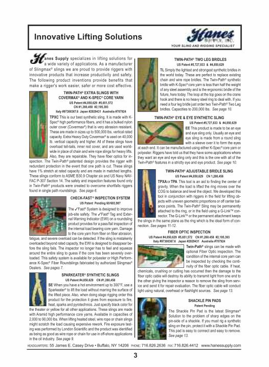
anes Supply specializes in lifting solutions fora wide variety of applications. As a manufacturer
of Slingmax® slings we are proud to provide riggers withinnovative products that increase productivity and safety.The following product inventions provide benefits thatmake a rigger's work easier, safer or more cost effective.
TWIN-PATH® EXTRA SLINGS WITHCOVERMAX® AND K-SPEC® CORE YARN
US Patent #4,850,629 #5,651,572CN #1,280,458 #2,195,393
Italy #97300367.6 Japan #2929431 Australia #707924TPXC This is our best synthetic sling. It is made with K-Spec® high performance fibers, and it has a bulked nylonouter cover (Covermax®) that is very abrasion resistant.These are made in sizes up to 500,000 lbs. vertical ratedcapacity. Extra Heavy Duty Covermax® is used on 40,000lb. vertical capacity and higher. All of these slings haveoverload tell-tails, inner red cover, and are used world-wide in place of chain and wire rope slings for heavy lifts.Also, they are repairable. They have fiber optics for in-
spection. The Twin-Path® patented design provides the rigger with redundant protection in the event that one path is cut. These slingshave 1% stretch at rated capacity and are made in matched lengths.These slings conform to ASME B30.9 Chapter six and US Navy NAV-FAC P-307 Section 14. The safety and inspection features found onlyin Twin-Path® products were created to overcome shortfalls riggersfound in single path roundslings. See page 6.
TWIN-PATH® TWO LEG BRIDLESUS Patent #5,727,833 & #4,850,629
TL Simply the lightest and strongest synthetic bridles inthe world today. These are perfect to replace existingchain and wire rope bridles. The Twin-Path® syntheticbridle with K-Spec® core yarn is less than half the weightof any steel assembly and is the ergonomic bridle of thefuture, here today. The loop at the top goes on the cranehook and there is no heavy steel ring to deal with. If youneed a four leg bridle just order two Twin-Path® Two Legbridles. Capacities to 200,000 lbs. See page 10.
TWIN-PATH® EYE & EYE SYNTHETIC SLINGUS Patent #5,727,833 & #4,850,629
EE This product is made to be an eyeand eye sling only. Usually an eye andeye sling is made from a round slingwith a sleeve over it to form the eyes
at each end. It can be manufactured using either K-Spec® core yarn orpolyester. Riggers have told us that they have some applications wherethey want an eye and eye sling only and this is the one with all of theTwin-Path® features in a strictly eye and eye product. See page 10.
TWIN-PATH® ADJUSTABLE BRIDLE SLINGUS Patent #4,850,629 CN 1,280,458
TPXAorTPA This tool is an aid to finding the center ofgravity. When the load is lifted the ring moves over theCOG to balance and level the object. We developed thistool in conjunction with riggers in the field for lifting ob-jects with uneven geometric proportions or off center bal-ance points. The Twin-Path® Sling may be permanentlyattached to the ring, or in the field using a G-LinkTM con-nector. The G-LinkTM or the permanent attachment keeps
the slings in the same plane as the ring which is the ideal form of con-nection. See pages 11-12.
FIBER OPTIC INSPECTIONUS Patent #4,850,629 #5,651,572 CN #1,280.458 #2,195,393
Italy #97300367.6 Japan #2929431 Australia #707924Twin-Path® slings can be made withoptional Fiber Optic inspection. Thecondition of the internal core yarn canbe inspected by checking the conti-nuity of the fiber optic cable. If heat,
chemicals, crushing or cutting has occurred then the damage to thefiber optic cable will destroy its ability to transmit light from one end tothe other giving the inspector a reason to remove the sling from serv-ice and send it for repair evaluation. The fiber optic cable will conductlight using natural, overhead or flashlight sources. See page 13.
SHACKLE PIN PADSPatent Pending
The Shackle Pin Pad is the latest Slingmax®Solution to the problem of sharp edges on the pin-side of a shackle. If you must rig a syntheticsling on the pin, protect it with a Shackle Pin Pad.This pad is easy to connect and easy to remove.See page 13.
CHECK-FAST® INSPECTION SYSTEMUS Patent Pending 60/683,987
The �Fast® System is designed to improvejob-site safety. The �Fast® Tag and Exter-nal Warning Indicator (EWI) on a roundslingproduct provides for a pass/fail inspection ofthe internal load bearing core yarn. Damageto the core yarn from fiber on fiber abrasion,
fatigue, and severe overload can be detected. If the sling is mistakenlyoverloaded beyond rated capacity, the EWI is designed to disappear be-fore the sling fails. The inspector no longer has to feel and squeezearound the entire sling to guess if the core has been severely over-loaded. This safety system is available for polyester or High Perform-ance K-Spec® Fiber Roundslings fabricated by authorized Slingmax®Dealers. See pages 7.
SPARKEATER® SYNTHETIC SLINGSUS Patent #4,850,629 CN #1,280,458
SEWhen you have a hot environment up to 300°F, use aSparkeater® to lift the load without marring the surface ofthe lifted piece. Also, when doing stage rigging order thisproduct for the protection it gives from exposure to fire,heat, sparks and pyrotechnics. Just specify black color for
the theater or yellow for all other applications. These slings are madewith Aramid high performance core yarns. Available in capacities of2,000 to 90,000 lbs. When lifting heated steel, wire rope or chain slingsmight scratch the load causing expensive rework. Fire exposure test-ing was performed by London Scientific and the product was identifiedas being as good as wire rope or chain for use in off-shore applicationsin the oil industry. See page 9.

Innovative lifting solutionsYOUR SLING AND RIGGING SPECIALIST
4HEADQUARTERS: 55 James E. Casey Drive • Buffalo, NY 14206 PHONE: 716.826.2636 FAX: 716.826.4412 www.hanessupply.com
CORNERMAX™ PADPatent Pending
The CornerMaxTM cut protection deviceprevents an edge on the load fromtouching the sling. In fact the edgedoesn’t even touch the CornerMaxTMprotector! This protector will handle the
most extreme circumstances lifting steel and concrete. CornerMaxTMPads are the latest in the line of sling protection from Slingmax®. See page 15.
CORNERMAX™ SLEEVEPatent Pending
The CornerMaxTM sleeve is the latest inrigging protection from Slingmax® Rig-ging Solutions. An ideal synthetic sleeveto protect slings from cutting whetherdue to curvature of the load edge orrepetitive uses, such as unloading steelcoils. See page 16.
G-LINK™ CONNECTORSUS Patent #5,651,573 CN #2,198,821Italy #97302680.0 Japan #Hei9-94730
Australia #710067The magic of one piece hardware that does somany things. You can use it on Twin-Path®, weband single path roundslings, for attaching hooksor rings, connecting two slings together, as slid-ing choker connection, as an adjustable sling,
as a choke lock connection or to shorten a sling’s reach. No parts, bolts,nuts, cotters, pins, or anything to look for. This is the only universal cou-pler designed with riggers in mind to fulfill all of their needs in the field.The G-LinkTM connector keeps the hardware such as hooks or rings inthe same plane as the sling. See page 17.
TRI-FLEX® WIRE ROPE SLINGUS Patent #4,043,581
This is a three part wire rope sling developed togive the rigger the advantages of strength com-bined with greater flexibility. It was created to re-place large diameter single part wire rope slingswhich proved awkward and stiff. Tri-Flex® Slingsare now manufactured in sizes from 1 ton to 145ton capacity. Steel erectors, millwrights and riggersuse Tri-Flex® Slings for everything from steel erec-
tion or machinery moving to any type of heavy lift. These slings aremade in matching lengths. See page 23-25.
GATOR-MAX™ SLINGUS Patent #5,561,973 and Patents Pending
This is the strongest multi-part sling with great flexi-bility. It will develop its full strength on small pins witha D/d ratio of 1/1 where D is the pin and d is the slingbody. (4/1 D/d when comparing the pin to the com-
ponent parts.) For heavy lifting work this is the most efficient wire ropesling that meets all of the standards. The eyes have the wire ropes (12)laid in parallel so that there is no cross over and then they are wrappedwith heavy duty material to keep them in position. It is an excellentchoice when you have to use small pins. This sling was developed tomeet conditions specified by the US Navy and the Wire Rope Techni-cal Board Sling Manual. See page 28.
GATOR-LAID® WIRE ROPE SLINGUS Patent #4,240,659 CN #1,082,755
This is identical to the Gator-Max® sling with theparallel eyes except it has metal sleeves for the
splice connection. This is the product when a big lift but shorter slingis required. It also has twelve parts of wire rope in the loop. TheGator-Flex® and Gator-Laid® products were developed in conjunction withthe off-shore oil industry to provide the worlds best heavy lift wire ropeslings. D/d ratios are the same as for the Gator-Max® sling. See page 29.
GATOR-FLEX® WIRE ROPE SLINGUS Patent #5,561,973
This sling has a nine part body style but the eyesare crossed or interwoven so that no wrapping isnecessary. The sling was developed in conjunc-
tion with riggers in the field that wished to create a sling for heavy liftsthat could be visually inspected and have the highest flexibility possi-ble in a multi-part wire rope sling. The D/d ratio of the sling body is 5:1and the eye loop is 1:1 where D is the pin or load diameter and d is thesling body diameter. See page 30-31.
T&D ULTRA-FLEX WIRE ROPE SLINGUS Patent #5,561,973
This wire rope sling is an extremely flexible product withgreat applications for general rigging purposes in the util-ity industry. It makes a fantastic choker sling especiallywhen lifting poles. Development was through a commit-tee composed of utility company workers and membersof the SLINGMAX® design team. D/d ratios are the sameas for the Gator-Flex® sling. See page 30-31.
GATOR-FLEX® NINE PART GROMMETUS Patent #5,561,973
Ultra flexible slings for that short heavy lift con-nection. These slings can be made shorterthan standard multi-part slings but maintain allof the advantages. The D/d ratio is 5:1 where
D is the pin or load and d is the sling body diameter. See page 27.
CHAIN SADDLE RINGUS Patent #4,241,575 CN #1,086,510 British #2,029,37
This product gives a chain bridle, length adjustment capa-bilities in each chain leg. It aids the rigger in placing the lift-ing point over the center of gravity so the load will lift in alevel manner. Different length chains or chains with different
attachments can be interchanged in the Saddle Ring for added utility.The Saddle Ring has found favor with millwrights for moving machin-ery in factories. See page 49.
GATOR-REX™ SLINGPatent Pending
This is the lastest high performance nine-part wire rope sling from Slingmax® Inc. Itsefficiencies are over 90%, meaning a riggercan get a lighter Gator-RexTM sling with thesame capacity as traditional nine-part slings.This sling features a hand-tuck body. It will de-velop its full strength on small pins with a D/dratio of 1:1 where D is the pin diameter and dis the sling body diameter. See page 26.

twin-Path® slingsYOUR SLING AND RIGGING SPECIALIST
5HEADQUARTERS: 55 James E. Casey Drive • Buffalo, NY 14206 PHONE: 716.826.2636 FAX: 716.826.4412 www.hanessupply.com
TWIN-PATH®
SLINGS IN ACTION
88 ton Refinery Compressor with CornerMaxTM Pads
500 ton Steam Generator Replacement Mark V Navy Assault Boat
Turbine Rotor Removal of 500 ton Bridge Decking Reactor Coolant Pump Motor
twin-Path® extra covermax® slingsYOUR SLING AND RIGGING SPECIALIST
6HEADQUARTERS: 55 James E. Casey Drive • Buffalo, NY 14206 PHONE: 716.826.2636 FAX: 716.826.4412 www.hanessupply.com
Do not eXceeD RateD caPacItY
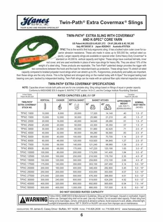
TWIN-PATH® EXTRA SLING WITH COVERMAX®AND K-SPEC® CORE YARN
US Patent #4,850,629 & #5,651,572 CN #1,280,458 & #2,195,393Italy #97300367.6 Japan #2929431 Australia #707924
TPXC This is the world’s first truly ergonomic sling. It has a bulked nylon outer cover for su-perior abrasion resistance. These are made in sizes up to 500,000 lbs. vertical rated ca-pacity. Larger capacity slings are available on special order. Extra Heavy Duty Covermax® is
standard on 40,000 lb. vertical capacity and higher. These slings have overload tell-tails, innerred cover, and are used worldwide in place of wire rope slings for heavy lifts. They are about 10% of the
weight of a steel sling. These products are repairable. The Twin-Path® patented design provides the rigger withtwo connections between the hook and the load for redundant back-up protection. These slings have 1% stretch at rated
capacity compared to braided polyester round slings which can stretch up to 9%. If ergonomics, productivity and safety are important,then these slings are the only choice. This is the lightest and strongest sling on the market today with K-Spec® the longest lasting loadbearing core yarn, backed by independent testing. Twin-Path slings can be made with an optional fiber optic internal inspection system.
TWIN-PATH® EXTRA COVERMAX® SPECIFICATIONSNOTE: Capacities shown include both paths and are for one complete sling. Sling ratings based on fittings of equal or greater capacity.
Conforms to ANSI/ASME B30.9 chapter 6, NAVFAC P-307 section 14.6.4.3, and the Cordage Institute Roundsling Standard.United States
Patent #4,850,629 RATED CAPACITIES (LBS.) 5:1 DF CanadianPatent #1,280,458
TWIN-PATH®EXTRA COVERMAX®
STOCK NO.
VERTICAL CHOKER VERTICALBASKET BASKET HITCHES APPROXIMATEWEIGHT
(LBS. PER FT.)(BEARING-BEARING)
NOMINALBODY WIDTH
(INCHES)90° 60° 45°
TPXC 1000 10,000 8,000 20,000 17,320 14,140 .40 1.5 - 3"
TPXC 1500 15,000 12,000 30,000 25,980 21,210 .45 1.5 - 3"
TPXC 2000 20,000 16,000 40,000 34,640 28,280 .51 1.5 - 3"
TPXC 2500 25,000 20,000 50,000 43,300 35,350 .57 1.5 - 3"
TPXC 3000 30,000 24,000 60,000 51,960 42,420 .71 2.0 - 4"
TPXC 4000 40,000 32,000 80,000 69,280 56,560 .83 2.0 - 4"
TPXC 5000 50,000 40,000 100,000 86,600 70,700 1.14 2.5 - 5"
TPXC 6000 60,000 48,000 120,000 103,920 84,840 1.27 2.5 - 5"
TPXC 7000 70,000 56,000 140,000 121,240 98,980 1.39 2.5 - 5"
TPXC 8500 85,000 68,000 170,000 147,220 120,190 1.65 3.0 - 6"
TPXC 10000 100,000 80,000 200,000 173,200 141,400 1.84 3.0 - 6"
TPXC 12500 125,000 100,000 250,000 216,500 176,750 2.35 4.0 - 8"
TPXC 15000 150,000 120,000 300,000 259,800 212,100 2.66 4.0 - 8"
TPXC 17500 175,000 140,000 350,000 303,100 247,450 3.14 5.0 - 10"
TPXC 20000 200,000 160,000 400,000 346,400 282,800 3.45 5.0 - 10"
TPXC 25000 250,000 200,000 500,000 433,000 353,500 4.07 5.0 - 10"
TPXC 27500 275,000 220,000 550,000 476,300 388,850 4.61 6.0 - 12"
TPXC 30000 300,000 240,000 600,000 519,600 424,200 4.92 6.0 - 12"
TPXC 40000 400,000 320,000 800,000 692,800 565,600 6.54 7.0 - 14"
TPXC 50000 500,000 400,000 1,000,000 866,000 707,000 8.15 8.0 - 16"
Follow OSHA, ASME B30.9 & Manufacturer’s Guidelines. Sling can fail if damaged, misused or overloaded. Inspectbefore use. Damaged sling shall not be used. Use only if trained. Do not exceed rated capacity. Protect sling frombeing cut by load edges, corners, protrusions & abrasive surfaces. Avoid exposure to acid, alkalis, ultraviolet light,sunlight & temperature above 180° F. DEATH or INJURY can occur from improper use or maintenance.
WARNING!

check-fast ® Inspection systemYOUR SLING AND RIGGING SPECIALIST
7HEADQUARTERS: 55 James E. Casey Drive • Buffalo, NY 14206 PHONE: 716.826.2636 FAX: 716.826.4412 www.hanessupply.com
The Check-Fast® System is designed to improve job-site safety. The �Fast® Tag and External Warning Indicator (EWI) on a roundsling product provides for a pass /fail inspection of the internal load bearing core yarn. Damage to the core yarn fromfiber on fiber abrasion, fatigue, and severe overload can bedetected. If the sling is mistakenly overloaded beyond rated ca-pacity, the EWI is designed to disappear before the sling fails.The inspector no longer has to feel and squeeze around the en-tire sling to guess if the core has been severely overloaded.This safety system is available for polyester or High Perform-ance K-Spec® Fiber Roundslings fabricated by authorizedSLINGMAX® Dealers.
CHECK-FAST® INSPECTION SYSTEMPatent Pending 60/683,987
INSTRUCTIONS FOR CHECK-FAST® INSPECTIONPatent Pending 60 /683,987
Read the information on the sling tag to identify the rated capacity for the hitch to be used, the type of coverand core, the manufacturers’ name, and the warnings and instructions on the tag. Be sure the information com-plies with existing standards.THEN:1. Inspect the circumference of the roundsling for holes, tears and other damage to the outer over.If damage is discovered, take the sling out of service and send it back to your Slingmax® dealer forevaluation. Do not use the sling.
2.Visually inspect the tag area and ensure the sling is equipped with the Check-Fast® Inspection Systemas evidenced by the black “�Fast® ” tag.
3.Visually inspect the tag area for the (EWI) External Warning Indicator. If the EWI is missing or not visible, take the sling out of service and send it back to your Slingmax® Dealer for evaluation. Do not use the sling.
SUMMARY: If there is no damage to the cover and the EWI is visible, the inspection is complete and the sling is a “GO!”
CHECK-FAST® INSPECTION SYSTEMNow available in Polyester or K-Spec® Single-Path and Twin-Path® Roundslings
FASTTM TAG AND EWI EXTEND FROM COVER EWI IS MISSING – FASTTM TAG PULLSEASILY OUT OF SLING
EXTERNALWARNING
INDICATOR(EWI)
GO NO-GO
FASTTM TAG AND EWI EXTEND FROM COVER EWI IS MISSING – FASTTM TAG PULLSEASILY OUT OF SLING
EXTERNALWARNING
INDICATOR(EWI)
GO NO-GOEXTERNALWARNINGINDICATOR
(EWI)
EWIMISSING
EWI IS MISSINGREMOVE FROM SERVICE
�FAST® TAG &EWI EXTEND FROM COVER

single-Path & twin-Path® High Performance slings with check-fast® system
YOUR SLING AND RIGGING SPECIALIST
8HEADQUARTERS: 55 James E. Casey Drive • Buffalo, NY 14206 PHONE: 716.826.2636 FAX: 716.826.4412 www.hanessupply.com HEADQUARTERS: 55 James E. Casey Drive • Buffalo, NY 14206 PHONE: 716.826.2636 FAX: 716.826.4412 www.hanessupply.com
RATED CAPACITIES (LBS.) 5:1 DF
TWIN-PATH®K-SPEC® SLINGSSTOCK NO.
VERTICAL CHOKER VERTICALBASKET BASKET HITCHES APPROXIMATEWEIGHT
(LBS. PER FT.)(BEARING-BEARING)
NOMINALBODY WIDTH
(INCHES)90° 60° 45°
TPXCF 1000 10,000 8,000 20,000 17,320 14,140 .40 1.5 - 3"TPXCF 1500 15,000 12,000 30,000 25,980 21,210 .45 1.5 - 3"TPXCF 2000 20,000 16,000 40,000 34,640 28,280 .51 1.5 - 3"TPXCF 2500 25,000 20,000 50,000 43,300 35,350 .57 1.5 - 3"TPXCF 3000 30,000 24,000 60,000 51,960 42,420 .71 2.0 - 4"TPXCF 4000 40,000 32,000 80,000 69,280 56,560 .83 2.0 - 4"TPXCF 5000 50,000 40,000 100,000 86,600 70,700 1.14 2.5 - 5"TPXCF 6000 60,000 48,000 120,000 103,920 84,840 1.27 2.5 - 5"TPXCF 7000 70,000 56,000 140,000 121,240 98,980 1.39 2.5 - 5"TPXCF 8500 85,000 68,000 170,000 147,220 120,190 1.65 3.0 - 6"
TPXCF 10000 100,000 80,000 200,000 173,200 141,400 1.84 3.0 - 6"TPXCF 12500 125,000 100,000 250,000 216,500 176,750 2.35 4.0 - 8"TPXCF 15000 150,000 120,000 300,000 259,800 212,100 2.66 4.0 - 8"TPXCF 17500 175,000 140,000 350,000 303,100 247,450 3.14 5.0 - 10"TPXCF 20000 200,000 160,000 400,000 346,400 282,800 3.45 5.0 - 10"TPXCF 25000 250,000 200,000 500,000 433,000 353,500 4.07 5.0 - 10"TPXCF 27500 275,000 220,000 550,000 476,300 388,850 4.61 6.0 - 12"TPXCF 30000 300,000 240,000 600,000 519,600 424,200 4.92 6.0 - 12"TPXCF 40000 400,000 320,000 800,000 692,800 565,600 6.54 7.0 - 14"TPXCF 50000 500,000 400,000 1,000,000 866,000 707,000 8.15 8.0 - 16"
RATED CAPACITIES (LBS.) 5:1 DF
TWIN-PATH®K-SPEC® SLINGSSTOCK NO.
VERTICAL CHOKER VERTICALBASKET BASKET HITCHES APPROXIMATEWEIGHT
(LBS. PER FT.)(BEARING-BEARING)
NOMINALBODY WIDTH
(INCHES)90° 60° 45°
SPXCF 500 5,000 4,000 10,000 8,660 7,070 .34 2.5"SPXCF 1000 10,000 8,000 20,000 17,320 14,140 .38 2.5"SPXCF 1500 15,000 12,000 30,000 25,980 21,210 .44 2.5"SPXCF 2000 20,000 16,000 40,000 34,640 28,280 .52 2.5"SPXCF 2500 25,000 20,000 50,000 43,300 35,350 .59 3"SPXCF 3000 30,000 24,000 60,000 51,960 42,420 .65 3"SPXCF 4000 40,000 32,000 80,000 69,280 56,560 .85 3"SPXCF 5000 50,000 40,000 100,000 86,600 70,700 .98 4"SPXCF 6000 60,000 48,000 120,000 103,920 84,840 1.11 4"SPXCF 7000 70,000 56,000 140,000 121,240 98,980 1.24 4"SPXCF 8500 85,000 68,000 170,000 147,220 120,190 1.63 5"
SPXCF 10000 100,000 80,000 200,000 173,200 141,400 1.81 5"
Do not eXceeD RateD caPacItY
Do not eXceeD RateD caPacItY
TWIN-PATH® EXTRA COVERMAX® WITH CHECK-FAST® INSPECTIONNOTE:Capacities shown include both paths and are for one complete sling. Sling ratings based on fittings of equal or greater capacity.
Conforms to ANSI/ASME B30.9 chapter 6, NAVFAC P-307 section 14.6.4.3, and the Cordage Institute Roundsling Standard.
SINGLE-PATH® EXTRA COVERMAX® WITH CHECK-FAST® INSPECTION
Follow OSHA, ASME B30.9 & Manufacturer’s Guidelines. Sling can fail if damaged, misused or overloaded. Inspectbefore use. Damaged sling shall not be used. Use only if trained. Do not exceed rated capacity. Protect sling frombeing cut by load edges, corners, protrusions & abrasive surfaces. Avoid exposure to acid, alkalis, ultraviolet light,sunlight & temperature above 180° F. DEATH or INJURY can occur from improper use or maintenance.
WARNING!
twin-Path® covermax® slings (Polyester)twin-Path® sparkeater slings (Aramid)
YOUR SLING AND RIGGING SPECIALIST
9HEADQUARTERS: 55 James E. Casey Drive • Buffalo, NY 14206 PHONE: 716.826.2636 FAX: 716.826.4412 www.hanessupply.com
RATED CAPACITIES (LBS.) 5:1 DF
TWIN-PATH®COVERMAX®STOCK NO.
VERTICAL CHOKER VERTICALBASKET BASKET HITCHES APPROXIMATEWEIGHT
(LBS. PER FT.)(BEARING-BEARING)
NOMINALBODY WIDTH
(INCHES)90° 60° 45°
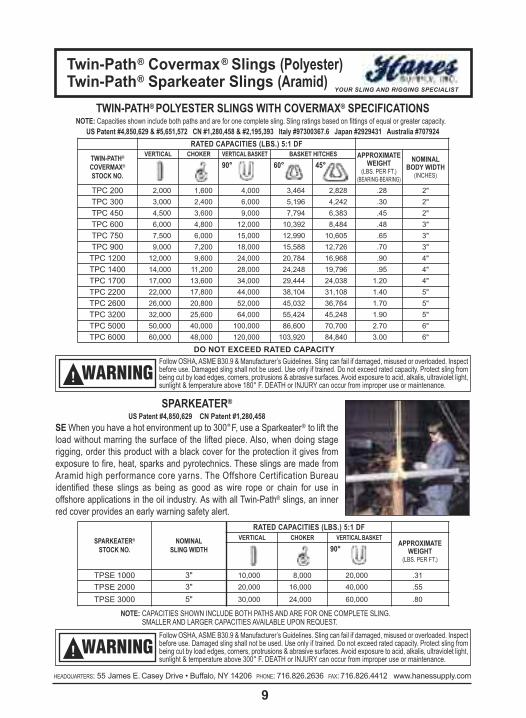
TPC 200 2,000 1,600 4,000 3,464 2,828 .28 2"TPC 300 3,000 2,400 6,000 5,196 4,242 .30 2"TPC 450 4,500 3,600 9,000 7,794 6,383 .45 2"TPC 600 6,000 4,800 12,000 10,392 8,484 .48 3"TPC 750 7,500 6,000 15,000 12,990 10,605 .65 3"TPC 900 9,000 7,200 18,000 15,588 12,726 .70 3"
TPC 1200 12,000 9,600 24,000 20,784 16,968 .90 4"TPC 1400 14,000 11,200 28,000 24,248 19,796 .95 4"TPC 1700 17,000 13,600 34,000 29,444 24,038 1.20 4"TPC 2200 22,000 17,800 44,000 38,104 31,108 1.40 5"TPC 2600 26,000 20,800 52,000 45,032 36,764 1.70 5"TPC 3200 32,000 25,600 64,000 55,424 45,248 1.90 5"TPC 5000 50,000 40,000 100,000 86,600 70,700 2.70 6"TPC 6000 60,000 48,000 120,000 103,920 84,840 3.00 6"
Do not eXceeD RateD caPacItY
TWIN-PATH® POLYESTER SLINGS WITH COVERMAX® SPECIFICATIONSNOTE: Capacities shown include both paths and are for one complete sling. Sling ratings based on fittings of equal or greater capacity.
US Patent #4,850,629 & #5,651,572 CN #1,280,458 & #2,195,393 Italy #97300367.6 Japan #2929431 Australia #707924
SPARKEATER®STOCK NO.
NOMINALSLING WIDTH
RATED CAPACITIES (LBS.) 5:1 DFVERTICAL CHOKER VERTICALBASKET
APPROXIMATEWEIGHT
(LBS. PER FT.)90°
TPSE 1000 3" 10,000 8,000 20,000 .31TPSE 2000 3" 20,000 16,000 40,000 .55
TPSE 3000 5" 30,000 24,000 60,000 .80
SPARKEATER®US Patent #4,850,629 CN Patent #1,280,458
SE When you have a hot environment up to 300°F, use a Sparkeater® to lift theload without marring the surface of the lifted piece. Also, when doing stagerigging, order this product with a black cover for the protection it gives from exposure to fire, heat, sparks and pyrotechnics. These slings are made fromAramid high performance core yarns. The Offshore Certification Bureau identified these slings as being as good as wire rope or chain for use in offshore applications in the oil industry. As with all Twin-Path® slings, an innerred cover provides an early warning safety alert.
NOTE: CAPACITIES SHOWN INCLUDE BOTH PATHS AND ARE FOR ONE COMPLETE SLING.SMALLER AND LARGER CAPACITIES AVAILABLE UPON REQUEST.
Follow OSHA, ASME B30.9 & Manufacturer’s Guidelines. Sling can fail if damaged, misused or overloaded. Inspectbefore use. Damaged sling shall not be used. Use only if trained. Do not exceed rated capacity. Protect sling frombeing cut by load edges, corners, protrusions & abrasive surfaces. Avoid exposure to acid, alkalis, ultraviolet light,sunlight & temperature above 300° F. DEATH or INJURY can occur from improper use or maintenance.
WARNING!
Follow OSHA, ASME B30.9 & Manufacturer’s Guidelines. Sling can fail if damaged, misused or overloaded. Inspectbefore use. Damaged sling shall not be used. Use only if trained. Do not exceed rated capacity. Protect sling frombeing cut by load edges, corners, protrusions & abrasive surfaces. Avoid exposure to acid, alkalis, ultraviolet light,sunlight & temperature above 180° F. DEATH or INJURY can occur from improper use or maintenance.
WARNING!

twin-Path® two leg bridlestwin-Path® eye and eye sling
YOUR SLING AND RIGGING SPECIALIST
10HEADQUARTERS: 55 James E. Casey Drive • Buffalo, NY 14206 PHONE: 716.826.2636 FAX: 716.826.4412 www.hanessupply.com HEADQUARTERS: 55 James E. Casey Drive • Buffalo, NY 14206 PHONE: 716.826.2636 FAX: 716.826.4412 www.hanessupply.com
TWIN-PATH® EYE & EYE SYNTHETIC SLINGUS Patent #5,727,833 & #4,850,629
EE Riggers have told us that they have some applications where they want an eyeand eye sling only and this is the one with all of the Twin-Path® features in a strictlyeye and eye product. Capacities below are in pounds.
TWIN-PATH® TWO LEG BRIDLESUS Patent #5,727,833 & #4,850,629
TL Simply the lightest and strongest synthetic bridles in the world today. These areperfect to replace existing chain and wire rope bridles. The Twin-Path® synthetic bri-dle with K-Spec® core yarn is less than half the weight of any steel assembly and isthe ergonomic bridle of the future, here today. The loop at the top goes on the cranehook and there is no heavy steel ring to deal with. If you need a four leg bridle, justorder two Twin-Path® Two Leg Bridles. Capacities to 200,000 lbs.
STOCK NUMBERS VERTICAL RC(LBS.)
HORIZONTAL ANGLES (LBS) WT. PER FT.(LBS.)
NORMALWIDTH60° 45°
TPXCTL 1000 10,000 8,500 7,000 .34 3"
TPXCTL 1500 15,000 12,700 10,500 .44 3"
TPXCTL 2000 20,000 17,000 14,000 .61 3"
TPXCTL 3000 30,000 25,500 21,000 .88 4"
TPXCTL 4000 40,000 34,000 28,000 1.23 5"
TPXCTL 5000 50,000 42,500 35,000 1.65 5"
STOCK NUMBERS CHOKER VERTICAL RC(LBS.)
BASKET60°
VERTICALBASKET
WT. PER FT.(LBS.)
NORMALWIDTH
TPXCEE 1000 8,000 10,000 17,320 20,000 .28 3"
TPXCEE 1500 12,000 15,000 25,980 30,000 .36 3"
TPXCEE 2000 16,000 20,000 36,640 40,000 .50 3"
TPXCEE 2500 20,000 25,000 43,300 50,000 .60 4"
TPXCEE 3000 24,000 30,000 51,960 60,000 .75 4"
TPXCEE 4000 32,000 40,000 69,280 80,000 1.00 5"
TPXCEE 5000 40,000 50,000 86,139 100,000 1.40 5"
TWIN-PATH® TWO LEG BRIDLES
TWIN-PATH® EYE AND EYE SLING
Follow OSHA, ASME B30.9 & Manufacturer’s Guidelines. Sling can fail if damaged, misused or overloaded. Inspectbefore use. Damaged sling shall not be used. Use only if trained. Do not exceed rated capacity. Protect sling frombeing cut by load edges, corners, protrusions & abrasive surfaces. Avoid exposure to acid, alkalis, ultraviolet light,sunlight & temperature above 180° F. DEATH or INJURY can occur from improper use or maintenance.
WARNING!

twin-Path® adjustable bridleYOUR SLING AND RIGGING SPECIALIST
11HEADQUARTERS: 55 James E. Casey Drive • Buffalo, NY 14206 PHONE: 716.826.2636 FAX: 716.826.4412 www.hanessupply.com
TPXA (WITH K-SPEC® FIBER), TPA (WITH POLYESTER)The Twin-Path® Adjustable Bridle is the ultimate multiple use rigging tool. It can be used in applications wherea standard two-leg or four leg bridle is used with the added advantage of self-adjustment to awkward loads.The Twin-Path® Adjustable Bridle self-adjusts over the center of gravity to find the lifting point. The Twin-Path®Adjustable Bridle can also be used as a complete rigging tool for choker, vertical, or basket hitches. The useof two or more Twin-Path® Adjustable Bridles facilitates lifts with multiple lifting points.
STOCKNUMBERS
BRIDALCAPACITY(LBS.)
NOMINALSLINGWIDTH
ADJUSTABLE RING DIMENSIONS SHACKLE DIMENSIONS SLING WEIGHT (LBS.)RINGSTOCK
DIAMETER
MAIN HOOKAREA(WIDTH)
RINGAREA
(LENGTH)
NOMINALSHACKLESIZE
TONNAGE(WLL)
APPROX3 FOOTBASE
APPROXADDER
PER FOOTTPA 6 6,000 2" 37/64" 2-1/2" 2-1/4" 5/8" 3-1/4T 4.40 1.35
TPXA 20 12,000 3" 13/16" 3" 2-5/8" 7/8" 6-1/2T 6.80 1.95
TPXA 40 20,000 4" 1-1/8" 4" 3-5/8" 1-1/4" 12T 13.60 2.70
TPXA 60 40,000 5" 1-5/8" 5-1/4" 4-3/4" 1-3/4" 25T 31.10 4.20
TPXA 90 60,000 5" 2" 7" 6-1/4" 2" 35T 60.00 5.70
TPXA 60 90,000 6" 2-1/4" 8" 7-1/4" 2-1/4" 55T 86.00 8.10
TWIN-PATH® ADJUSTABLE BRIDLE SPECIFICATIONS
NOTE: CAPACITIES SHOWN ARE FOR ENTIRE BRIDLE ASSEMBLY WITH LEGS @ 45° ANGLE.Do not eXceeD RateD caPacItY
MetRIc caPacItIes aVaIlable
Follow OSHA, ASME B30.9 & Manufacturer’s Guidelines. Sling can fail if damaged, misused or overloaded. Inspectbefore use. Damaged sling shall not be used. Use only if trained. Do not exceed rated capacity. Protect sling frombeing cut by load edges, corners, protrusions & abrasive surfaces. Avoid exposure to acid, alkalis, ultraviolet light,sunlight & temperature above 180° F. DEATH or INJURY can occur from improper use or maintenance.
WARNING!

twin-Path® adjustable bridleYOUR SLING AND RIGGING SPECIALIST
12HEADQUARTERS: 55 James E. Casey Drive • Buffalo, NY 14206 PHONE: 716.826.2636 FAX: 716.826.4412 www.hanessupply.com HEADQUARTERS: 55 James E. Casey Drive • Buffalo, NY 14206 PHONE: 716.826.2636 FAX: 716.826.4412 www.hanessupply.com
The Twin-Path® Adjustable Bridle sling is a multi-purpose rigging tool and it's important that it is usedproperly. The adjustment ring has a double sling on one side and a single sling on the other side.
If the lifting points are an equal distance from thecenter of gravity, then the Twin-Path® Adjustablecan be hooked-up with the double or single slingon either lifting point.
If the lifting points are an equal distance oneither side of the center of gravity but one ishigher, then the double sling should be attached tothe higher lifting point.
If one of the lifting points is closer to the center ofgravity, then attach the double sling to this liftingpoint. It will have the highest weight concentration.If the Twin-Path® Adjustable is attached so that thesingle sling is nearest the center of gravity, it willnot allow the lift to be made.
Never use the Twin-Path® Adjustable Bridle in sit-uations where the sling-to-hook angle is greaterthan 45°. Always connect above the center ofgravity. If connections are made below the centerof gravity, then the load may turn when lifted.
Follow OSHA, ASME B30.9 & Manufacturer’s Guidelines. Sling can fail if damaged, misused or overloaded. Inspectbefore use. Damaged sling shall not be used. Use only if trained. Do not exceed rated capacity. Protect sling frombeing cut by load edges, corners, protrusions & abrasive surfaces. Avoid exposure to acid, alkalis, ultraviolet light,sunlight & temperature above 180° F. DEATH or INJURY can occur from improper use or maintenance.
WARNING!

Fiber Optic InspectionShackle Pin Pads
YOUR SLING AND RIGGING SPECIALIST
13HEADQUARTERS: 55 James E. Casey Drive • Buffalo, NY 14206 PHONE: 716.826.2636 FAX: 716.826.4412 www.hanessupply.com
SHACKLE PIN PADSPatent Pending
The pin area of a shackle can cause synthetic slings to cut and placing synthetic slings on the pin should be avoided. Even a newshackle can have a sharp edge where the threaded pin goes through theshackle ear. If the sling is exposed to this area, it can cut and fail. TheShackle Pin Pad is the latest SLINGMAX® SOLUTION in the constanteffort to ensure the ultimate rigging safety of our customers. If you mustrig on the pin, protect your sling with a Shackle Pin Pad.
• Protects sling along entire pin including ear seams.• Three connection points secure pad to shackle.• Take on and off in seconds.
OPTIONAL FIBER OPTIC INSPECTION FOR TWIN-PATH® SLINGSUS Patent #4,850,629 #5,651,572 CN #1,280,458 #2,195,393 Italy #97300367.6 Japan #2929431 Australia #707924
Twin-Path® slings have an optional Fiber Optic inspec-tion system. The condition of the internal core yarn canbe inspected just by checking the continuity of the fiberoptic cable. If crushing or cutting, heat or chemical dam-age, has occurred then the damage to the fiber opticcable will destroy its ability to transmit light from one endto the other giving the inspector a reason to remove thesling from service and send it in for repair evaluation.The fiber optic cable will conduct light using natural, overhead or flashlight sources. The inspector simply covers and removes his finger from one end and watches the other end for blinking which indicates that thesling is OK to use for another lift.
Follow OSHA, ASME B30.9 & Manufacturer’s Guidelines. Sling can fail if damaged, misused or overloaded. Inspectbefore use. Damaged sling shall not be used. Use only if trained. Do not exceed rated capacity. Protect sling frombeing cut by load edges, corners, protrusions & abrasive surfaces. Avoid exposure to acid, alkalis, ultraviolet light,sunlight & temperature above 180° F. DEATH or INJURY can occur from improper use or maintenance.
WARNING!

twin-Path® slingsYOUR SLING AND RIGGING SPECIALIST
14HEADQUARTERS: 55 James E. Casey Drive • Buffalo, NY 14206 PHONE: 716.826.2636 FAX: 716.826.4412 www.hanessupply.com HEADQUARTERS: 55 James E. Casey Drive • Buffalo, NY 14206 PHONE: 716.826.2636 FAX: 716.826.4412 www.hanessupply.com
220 ton Cement Kiln
F-15 Level Lift with Adjustable Bridles Transporting a 500 ton Electric Generator
Removing Nuclear Reactor Lid Sections
40 ton Electric Transformer 90 ton Oil Rig Thruster
TWIN-PATH®SLINGS...
DO THE JOBDO THE JOB
synthetic armor Pads (Abrasion Protection)cornerMaxtM Pads (Edge Protection)
YOUR SLING AND RIGGING SPECIALIST
15HEADQUARTERS: 55 James E. Casey Drive • Buffalo, NY 14206 PHONE: 716.826.2636 FAX: 716.826.4412 www.hanessupply.com
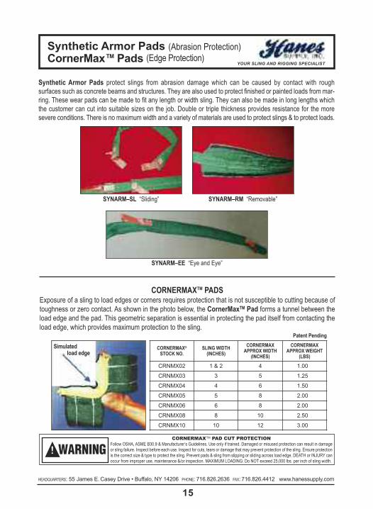
Synthetic Armor Pads protect slings from abrasion damage which can be caused by contact with rough surfaces such as concrete beams and structures. They are also used to protect finished or painted loads from mar-ring. These wear pads can be made to fit any length or width sling. They can also be made in long lengths whichthe customer can cut into suitable sizes on the job. Double or triple thickness provides resistance for the more severe conditions. There is no maximum width and a variety of materials are used to protect slings & to protect loads.
SYNARM–SL “Sliding” SYNARM–RM “Removable”
SYNARM–EE “Eye and Eye”
Simulatedload edge
Patent Pending
CORNERMAXTM PADSExposure of a sling to load edges or corners requires protection that is not susceptible to cutting because oftoughness or zero contact. As shown in the photo below, the CornerMaxTM Pad forms a tunnel between theload edge and the pad. This geometric separation is essential in protecting the pad itself from contacting theload edge, which provides maximum protection to the sling.
CORNERMAX®STOCK NO.
SLING WIDTH(INCHES)
CORNERMAXAPPROX WIDTH
(INCHES)
CORNERMAXAPPROX WEIGHT
(LBS)
CRNMX02 1 & 2 4 1.00
CRNMX03 3 5 1.25
CRNMX04 4 6 1.50
CRNMX05 5 8 2.00
CRNMX06 6 8 2.00
CRNMX08 8 10 2.50
CRNMX10 10 12 3.00
CORNERMAXTM PAD CUT PROTECTIONFollow OSHA, ASME B30.9 & Manufacturer’s Guidelines. Use only if trained. Damaged or misused protection can result in damageor sling failure. Inspect before each use. Inspect for cuts, tears or damage that may prevent protection of the sling. Ensure protectionis the correct size & type to protect the sling. Prevent pads & sling from slipping or sliding across load edge. DEATH or INJURY canoccur from improper use, maintenance &/or inspection. MAXIMUM LOADING: Do NOT exceed 25,000 lbs. per inch of sling width.
WARNING!

cornerMax sleeve (Cut Protection)YOUR SLING AND RIGGING SPECIALIST
16HEADQUARTERS: 55 James E. Casey Drive • Buffalo, NY 14206 PHONE: 716.826.2636 FAX: 716.826.4412 www.hanessupply.com HEADQUARTERS: 55 James E. Casey Drive • Buffalo, NY 14206 PHONE: 716.826.2636 FAX: 716.826.4412 www.hanessupply.com
The CornerMaxTM Sleeve is the latest in rigging protection from SLINGMAX® Rigging Solutions. The Corner-MaxTM Sleeve is the ideal solution to protect synthetic slings from cutting when it is not practical to use a CornerMaxTM Pad, whether due to curvature of the load edge or repetitive uses such as unloading steel coils.Independent field and laboratory testing has shown the CornerMaxTM Sleeve to be extremely cut resistant. The CornerMaxTM Sleeve is made with Dyneema® Fiber and is proven tough. To prevent sliding, the 6" wideCornerMaxTM Sleeve has been sewn down the middle (5") on each end of the Twin-Path® Extra Sling (pictured).The true benefits of this revolutionary material far outweigh the costs and now provide for the use of syntheticslings in applications previously dominated by heavy chain, mesh and wire rope slings.
Twin-Path® Coil Sling• 10 times lighter than conventional steel coil gripper slings.• Chain and metal mesh slings require rigger to use a “fish hook” to grab & pull the sling through the coil. The Twin-Path® Coil Sling is so light that one underhanded toss is all you need. Also faster to make.
• Will not damage the load.• Repairable as manufacturer can remove a damaged CornerMaxTM sleeve & sew a new one to the sling.
NEW PRODUCT CORNERMAX®STOCK NO.
EXTERNAL SLEEVEWIDTH
FASTENED OVERBOTH LEGS OF
TWIN-PATH® SLING
CRNMXS04 6 INCH UP TO TPXC 5000
CORNERMAXTM PAD CUT PROTECTIONFollow OSHA, ASME B30.9 & Manufacturer’s Guidelines. Use only if trained. Damaged or misused protection can result in damageor sling failure. Inspect before each use. Inspect for cuts, tears or damage that may prevent protection of the sling. Ensure protectionis the correct size & type to protect the sling. Prevent pads & sling from slipping or sliding across load edge. DEATH or INJURY canoccur from improper use, maintenance &/or inspection. MAXIMUM LOADING: Do NOT exceed 25,000 lbs. per inch of sling width.
WARNING!

G-linktM synthetic sling connectorYOUR SLING AND RIGGING SPECIALIST
17HEADQUARTERS: 55 James E. Casey Drive • Buffalo, NY 14206 PHONE: 716.826.2636 FAX: 716.826.4412 www.hanessupply.com
SPECIFICATIONS:
PRODUCT FEATURES:� Couples web, round or Twin-Path® slings with hardware (oblongs or hooks).� Splices two slings into longer length.� Connects two slings with oblong and two hooks into bridle sling.� Allows sling to be used as sliding choker sling.� Two G-LinkTM connectors used together will double the rated capacityof one G-LinkTM connector.
� Conforms with ASME B30.9 web and round sling specifications.� Shortens sling reach.
US Patent #5,651,573 CN #2,198,821Italy #97302680.0 Japan #Hei9-94730
Australia #710067
Choker Sling Connect Two SlingsConnect Hook or Oblong to Sling
Shorten Slings
MODELNUMBER
VERTICALRATED
CAP. TONS
CHOKERLRATED
CAP. TONS
SLINGSIZE
(INCHES)WEIGHT(LBS)
SC200L 2-1/2 2 2 2
SC300L 5 3 3 3-1/2
SC400L 7-1/2 4 4 7
SC500L 15 8 5 15
SC600L 25 12 6 29
Follow OSHA, ASME B30.9 & Manufacturer’s Guidelines. Can fail if damaged, misused or overloaded. Inspect before use. Use only if trained. Observe rated capacity. DEATH or INJURYcan occur from improper use or maintenance.
WARNING!

flip over twin-Path® slingsYOUR SLING AND RIGGING SPECIALIST
18HEADQUARTERS: 55 James E. Casey Drive • Buffalo, NY 14206 PHONE: 716.826.2636 FAX: 716.826.4412 www.hanessupply.com HEADQUARTERS: 55 James E. Casey Drive • Buffalo, NY 14206 PHONE: 716.826.2636 FAX: 716.826.4412 www.hanessupply.com
Subsea Stack/Tree Laydown
Electric Generator Recovery from Fall Off Railcar
Ship Module
Nuclear Reactor Head Turning

twin-Path® slingsYOUR SLING AND RIGGING SPECIALIST
19HEADQUARTERS: 55 James E. Casey Drive • Buffalo, NY 14206 PHONE: 716.826.2636 FAX: 716.826.4412 www.hanessupply.com
7.0 - Mechanical Considerations7.1 Determine the weight of the load. The weight of the load shall be within the rated capacity of the sling.
7.2 Select a sling having suitable characteristics for the type of load, hitch and environment.
7.3 Slings shall not be loaded in excess of the rated capacity. Consideration shall be given to angle of lift whichmay affect the lifting capacity. Diameters of pins and edges also may affect the capacity of the liftingsling.
7.4 Slings used in a choker shall not be forced to tighten around the load by pounding with hammers or otherobjects. Choker hitches are the least effective way to use a sling based on capacity. Two chokers shouldbe used to balance the load. One choker in the center of the load may create an unbalanced situationwhich could lead to an accident.
7.5 Slings used in a basket hitch must have the load balanced to prevent slippage and accidents.
7.6 Slings used with fittings shall be compatible with the fittings used. The lifting capacity shallbe rated at thelower of the fitting or sling. Fitting openings shall be of the proper shape and size to assure that the slingwill seat properly.
7.7 Slings shall be protected from cutting and edges. All protrusions and abrasive surfaces will be kept fromcontact with the sling. Where unavoidable situations develop padding shall be placed between the slingand the load. The pin area of a shackle can cause synthetic slings to cut and placing syntheticslings on the pin should be avoided unless it is protected.
7.8 Slings shall not be dragged on the floor or drawn across other surfaces which may damage the sling.
7.9 Slings shall not be twisted or tied in knots to shorten.
7.10 Slings shall not be pulled from under loads resting on the sling.
7.11 Do not drop objects on slings or run over them with vehicles.
7.12 Slings which are damaged shall not be used.
7.13 Sling hitches must provide control of the load.
7.14 Portions of the human body shall be kept from between the sling and the load and from between the slingand any attachment to lifting devices such as hooks.
7.15 Personnel shall stand clear of suspended loads.
7.16 Personnel shall not ride on the sling or suspended loads.
7.17 Avoid snatch or shock loading.
7.18 Twisting and kinking the legs of the sling shall be avoided.
7.19 Load applied to the hook should be centered in the bowl of the hooks. Do not point load the hook.
7.20 During lifting with or without the load all personnel shall be alert for possible snagging.

7.0 - Mechanical Considerations7.21 The slings should contain or support the load from the sides above the center of gravity so that the load
will not tilt when the load is lifted.7.22 Slings shall be of the proper length so that the angle of the sling to the load does not reduce the rated
capacity of the sling for a given angle.7.23 Use only if trained. Read and understand tag. Only legibly marked or labeled slings must be used.
If the tag is not legible, or missing, the sling must not be used.7.24 Keep labels or tags away from the load, the hook and the angle of choke.7.25 Synthetic slings should be inspected each time before each lift.
8.0 - Environmental Considerations8.1 When not in use, synthetic slings should be stored in a clean dry place. Heat sources and non-ven-
tilated places should be avoided.8.2 Chemically active environments can affect the strength of synthetic lifting slings. Different chemicals will
react with different exposure to Covermax® bulked nylon, polyester, aramids, and Olefins. Aramids are resistant to most ketones, alcohols, dry cleaning solvents and many other organic solvents. Its acidresistance is superior to that of nylon but is not as good as that of polyester. Aramids show good resistance toalkalis at room temperature, but is degraded by strong alkalis at higher temperatures.Aramids are compatible with fluorine-containing elastomers, resins, and refrigerants at high temperatures,and is resistant to fluorine compounds in concentrations usually encountered in stack gases from metallurgi-cal and rock-processing operations.The resistance of aramids to oxides of sulphur at temperatures above the acid dew point is superior to that of polyester. Below the dew point, concentrated sulphuric acid may condense on the fiber and cause a progres-sive loss in strength.In moderate to strong acid or alkali environments, evaluation of aramids should be made to ensure that the yarnwill perform acceptably before use.Polyester and nylon are not significantly affected by most compounds of the following classes: Alcohols, DryCleaning Solvents, Halogenated Hydrocarbons, Ketones, Soaps and Synthetic Detergents, and Water(Including Sea Water).Polyester also shows good to excellent resistance to:
• Aqueous solutions of most weak acids at the boil, and to most strong acids at room temperature, but is disintegrated by concentrated (95%) sulphuric acid at room temperature.
• Aqueous solutions of strong alkalis at room temperature, but is degraded at the boil.• Oxidizing agents, and is not degraded by bleaching treatments ordinarily used for textiles.
Nylon is not significantly affected by most aldehydes, alkalis, ethers, or hydrocarbons, but is deteriorated by dilute acids (e.g., hydrochloric acid and sulphuric acid in 10% concentrations at room temperature cause anoticeable loss in breaking strength in 10 hours).
twin-Path® slingsYOUR SLING AND RIGGING SPECIALIST
20HEADQUARTERS: 55 James E. Casey Drive • Buffalo, NY 14206 PHONE: 716.826.2636 FAX: 716.826.4412 www.hanessupply.com HEADQUARTERS: 55 James E. Casey Drive • Buffalo, NY 14206 PHONE: 716.826.2636 FAX: 716.826.4412 www.hanessupply.com

Solvents for nylon includes: Concentrated formic acid, Phenolic compounds at room temperature, Calciumchloride in methanol at room temperature.
Hot solutions of calcium chloride in: Glacial Acetic Acid, Ethylene Chlorohydrin, Ethylene Glycol.
Hot solutions of zinc chloride in methanol Benzyl alcohol at the boil.
Aramids are resistant to most weak acids and alkalis, ketones, alcohols, hydrocarbons, oils and dry cleaningsolvents. Strong acids and bases and sodium hypo-chlorite bleach attack aramids, particularly at high tem-peratures of high concentrations.
K-Spec® core yarn strength retention is based on test results of components at 65°C/150°F (or less) for 6months. K-Spec® has a 100% strength retention when exposed to: Age,10% detergent solution, rot and mildew,sunlight and Toluene; 99% strength retention when exposed to: acetic acid, gasoline, hydrochloric acid 1m, hy-draulic fluid, kerosene, and sea water; 98% retention when exposed to: 25% ammonium hydroxide, 10% hy-pophosphite solution, and 40% phosphoric acid; 97% retention when exposed to 5m sodium hydroxide; 95%retention when exposed to Portland cement and sulfuric acid; and 88% retention when exposed to Clorox®, andnitric acid.
9.0 - Fiber Characteristics(Using Nylon as a basis of 1.0)
Generic Fiber Polypro- HDPEType Nylon Polyester Pylene Olefin Aramid K-Spec®
Bulk Strength1 1.0 .9 - 1.1 .55 2.8 2.7 2.75Weight 1.0 1.21 .80 .85 1.26 1.01Working2 Elastic 1.0 .60 .80 .10 .10 .10Elongation
Co-efficient3 of .10 -.12 .12 - .15 .15 - .22 .08 .10 - .12 .10Friction
Chars at Chars atMelting Point 460°F 480°F 330°F 297°F 800°F 297°FCritical4 Temperature 180°F 180°F 180°F 150°F 300°F 180°FSpecific Gravity 1.14 1.38 .91 .97 1.44 1.2Cold-Flow (Creep)5 Negligible Negligible Negligible Negligible Negligible Negligible
to High to High
1Bulk Strength is defined as strength per circumference squared.2Working is defined as rope actually in use under a cycling load.3Co-efficient of friction is based on reluctance to slip or slide.4Critical temperature is defined as the point at which degradation is caused by temperature alone.5Cold-Flow (Creep) is defined as fiber deformation (elongation) due to molecular slippage under a constant steady static load-ing situation. Fibers that have this inherent characteristic will display extremely low or negligible creep if minor fluctuations occurin the rate and/or frequency of load levels. In rope form, this would apply to polypropylene, polyethylene, and HDPE Olefin fibers.
twin-Path® slingsYOUR SLING AND RIGGING SPECIALIST
21HEADQUARTERS: 55 James E. Casey Drive • Buffalo, NY 14206 PHONE: 716.826.2636 FAX: 716.826.4412 www.hanessupply.com

twin-Path® slingsYOUR SLING AND RIGGING SPECIALIST
22HEADQUARTERS: 55 James E. Casey Drive • Buffalo, NY 14206 PHONE: 716.826.2636 FAX: 716.826.4412 www.hanessupply.com HEADQUARTERS: 55 James E. Casey Drive • Buffalo, NY 14206 PHONE: 716.826.2636 FAX: 716.826.4412 www.hanessupply.com
10.0 - Inspections of Twin-Path® Products10.1 Tell-Tails should extend past the tag area of each sling. If both Tell-Tails are not visible, remove the sling
from service. If any part of the sling shows evidence of chemical degradation, remove it from service. Sendto manufacturer for repair evaluation.
10.2 Slings should be inspected for evidence of cutting or tearing of the outer cover. Slings with cuts shouldbe removed from service and sent back to the manufacturer for repair evaluation. Damage to the covermay indicate core damage.
10.3 Inspect slings for evidence of heat damage. Aramid Sparkeater Slings should not be exposed to tem-peratures over 149°C/300°F. K-Spec® and Polyester Core Slings should not be exposed to temperaturesabove 82°C/180°F. Cold temperature exposure down to minus 40°C/minus 40°F do not effect the strengthof the products. Other temperatures should be referred to the manufacturer.
10.4 Slings using aluminum fittings shall not be used where fumes, vapors, sprays, or mists of alkalis or acidsare present.
10.5 Twin-Path® Lifting Slings and any fittings attached should be the subject of frequent and regular inspec-tions. In addition to the initial inspection by a competent person and frequent written inspections, theslings should be visually inspected before each use.
10.6 Written inspections should be performed as required and documents of such inspection by a competentperson shall be kept on file in the safety department of the plant or site where used. Inspections may bedone more often based on frequency of use, severity of conditions, experience of past service life.
10.7 Slings should be examined throughout their length for abrasion, cuts, heat damage, fitting distortion ordamage, tag legibility, and if any doubts are held by the inspector, the sling should be removed fromservice. Core integrity is determined by fiber optic light transfer if this type of tell-tail is installed in the sling.If a deterioration is found, the sling must be removed from service and returned to the manufacturer forevaluation.
10.8 Slings removed from service that are not capable of repair should be destroyed and rendered completelyunfit for future use.
10.9 Abrasion, heat damage or cuts to the cover may indicate a loss of strength to the load core and theseslings should not be used until evaluated by the manufacturer. At area of damage, cover should beopened and the core yarns counted and visually inspected.
11.0 - Test Procedures for Complete Twin-Path® Sling Products11.1 For proof testing, the pins shall be 1˝ diameter or larger.11.2 Proof tests shall consist of pulling the slings to twice their rated capacity. Slings shall be held at the proof
test limit for a minimum of 15 seconds and then the tension may be released.11.3 Testing of Twin-Path® Sling products and load yarn shall be on a testing machine, which meets or exceeds
the standards as described in ASME E-4.11.4 Break testing of slings shall be as above with results documented. Pin size for break testing should be a
diameter equal to half the nominal sling width, or larger.11.5 Proof testing is mandatory for every newly manufactured and repaired Twin-Path® sling.11.6 After the sling is proof tested, the Tell-Tails should then be trimmed to length prior to shipment.11.7 Repaired fittings or slings shall be proof-tested before they are returned to service.
THESE RECOMMENDED STANDARD SPECIFICATIONS HAVE BEEN FORMULATED AS A GUIDE TO USERS, INDUSTRY AND GOVERNMENT TO INSURE THE PROPER USE, MAINTENANCE AND INSPECTION OF TWIN-PATH® LIFTING SLING PRODUCTS.

tri-flex® slingsYOUR SLING AND RIGGING SPECIALIST
23HEADQUARTERS: 55 James E. Casey Drive • Buffalo, NY 14206 PHONE: 716.826.2636 FAX: 716.826.4412 www.hanessupply.com
tRI-fleX slInGs In actIon

tri-flex® sling engineeringYOUR SLING AND RIGGING SPECIALIST
24HEADQUARTERS: 55 James E. Casey Drive • Buffalo, NY 14206 PHONE: 716.826.2636 FAX: 716.826.4412 www.hanessupply.com HEADQUARTERS: 55 James E. Casey Drive • Buffalo, NY 14206 PHONE: 716.826.2636 FAX: 716.826.4412 www.hanessupply.com
CERTIFIED PROOF TESTINGSLINGS – WIRE ROPE – CHAIN – NYLON – FITTINGS
TRI-FLEX® ENGINEERING INFORMATION
PIN SIZE EQUALSD/d OF 4:1 USING
COMPONENT PARTS
Patent #4,043,581
TRI-FLEX® WIRE ROPE SLINGS provide the best combination of strength and flexibility. Because of the patented TRI-FLEX® SLING construction, there is a large savings in material and machine costs in the larger sizes; this, combined with ease of use make TRI-FLEX® SLINGS the only sling for smart buyers.
BASKET HITCH EQUALSD/d OF 5:1 USING
FINISHED DIAMETER
COMPOSED3 PARTS OFEIP ROPE
DESIGN FACTOR 5:1 RATED LOAD IN TONS FINISHEDACTUALDIAMETER
WEIGHTPER FT.LBS.VERTICAL CHOKER VERTICAL BASKET
1/4" 1.7 1.3 3.4 1/2" .445/16" 2.6 1.9 5.2 5/8" .683/8" 3.6 2.7 7.2 3/4" .99
7/16" 4.9 3.7 9.8 7/8" 1.331/2" 6.4 4.8 12.8 1" 1.75
9/16" 8.0 6.0 16.0 1-1/8" 2.245/8" 9.9 7.4 19.8 1-1/4" 2.733/4" 14.0 10.5 28.0 1-1/2" 3.97/8" 19.0 14.3 49.6 1-3/4" 5.41" 24.8 18.6 62.4 2" 7.0
1-1/8" 31.2 23.4 76.8 2-1/4" 8.91-1/4" 38.4 28.8 92.0 2-1/2" 10.01-3/8" 46.0 34.5 130.0 2-3/4" 13.31-1/2" 55.0 41.2 110.0 3" 15.81-5/8" 63.4 47.6 126.8 3-1/4" 18.51-3/4" 73.0 54.8 146.0 3-1/2" 21.5
2" 95.0 71.2 190.0 4" 28.02-1/4" 118.0 88.5 236.0 4-1/2" 35.62-1/2" 145.0 109.0 290.0 5" 44.0
Follow OSHA, ASME B30.9 & Manufacturer’s Guidelines. Can fail if damaged, misused or overloaded. Inspect before use.Use only if trained. Do not exceed rated capacity. Protect sling from being cut by load edges, corners, protrusions & abrasivesurfaces. Avoid environments stated on Warning Tag. DEATH or INJURY can occur from improper use or maintenance.
WARNING!

tri-flex® sling systemYOUR SLING AND RIGGING SPECIALIST
25HEADQUARTERS: 55 James E. Casey Drive • Buffalo, NY 14206 PHONE: 716.826.2636 FAX: 716.826.4412 www.hanessupply.com
TRI-FLEX® SLING SYSTEMU.S. Patent #4,240,659; CN Patent #1,082,755
British #2,029,796This product is a combination of three Tri-Flex®Wire Rope slings wrapped together helically to forma nine part finished body sling. After a heavy lift isfinished, the product can be taken apart to formthree individual Tri-Flex® slings for smaller liftingwork. This product was developed for constructionprojects where there are a few heavy lifts. A supe-rior strength sling because it has twelve parts ofwire rope in the loop for greater strength than tradi-tional nine part wire rope slings that have only tenparts of wire rope in the loops.
DIAMETER OFCOMPONENT
PARTS
ONE TRI-FLEX® SLING3 PARTS EIP
PIN DIAMETER =4x’s COMPONENT PART
THREE TRI-FLEX® SLINGS9 PARTS EIP
PIN DIAMETER =4x’s COMPONENT PART
NINE TRI-FLEX® SLINGS27 PARTS EIPPIN DIAMETER =
8x’s COMPONENT PART
VERTICALRATED LOAD
FINISHEDDIAMETER
VERTICALRATED LOAD
FINISHEDDIAMETER
VERTICALRATED LOAD
FINISHEDDIAMETER
1/4" 1.7 1/2" 4.6 1" 12.9 2"5/16" 2.6 5/8" 7.0 1-1/4" 19.9 2-1/2"3/8" 3.6 3/4" 10.0 1-1/2" 28.5 3"
7/16" 4.9 7/8" 13.8 1-3/4" 38.6 3-1/2"1/2" 6.4 1" 18.0 2" 50.0 4"
9/16" 8.0 1-1/8" 22.7 2-1/4" 63.5 4-1/2"5/8" 9.9 1-1/4" 27.8 2-1/2" 78.0 5"3/4" 14.0 1-1/2" 39.7 3" 110.0 6"7/8" 19.0 1-3/4" 53.7 3-1/2" 150.0 7"1" 24.8 2" 69.8 4" 195.0 8"
1-1/8" 31.2 2-1/4" 87.7 4-1/2" 245.0 9"1-1/4" 38.4 2-1/2" 108.0 5" 302.0 10"1-3/8" 46.0 2-3/4" 130.0 5-1/2" 363.0 11"1-1/2" 55.0 3" 154.0 6" 430.0 12"1-5/8" 63.4 3-1/4" 178.0 6-1/2" 499.0 13"1-3/4" 73.0 3-1/2" 206.0 7" 578.0 14"
2" 95.0 4" 267.0 8" 748.0 16"2-1/4" 118.0 4-1/2" 333.0 9" 934.0 18"2-1/2" 145.0 5" 408.0 10" 1140.0 20"
NOTE: Rated load with 5:1 DF. Rated loads are in tons.
Follow OSHA, ASME B30.9 & Manufacturer’s Guidelines. Can fail if damaged, misused or overloaded. Inspect before use.Use only if trained. Do not exceed rated capacity. Protect sling from being cut by load edges, corners, protrusions & abrasivesurfaces. Avoid environments stated on Warning Tag. DEATH or INJURY can occur from improper use or maintenance.
WARNING!

Gator-RextM slingYOUR SLING AND RIGGING SPECIALIST
26HEADQUARTERS: 55 James E. Casey Drive • Buffalo, NY 14206 PHONE: 716.826.2636 FAX: 716.826.4412 www.hanessupply.com HEADQUARTERS: 55 James E. Casey Drive • Buffalo, NY 14206 PHONE: 716.826.2636 FAX: 716.826.4412 www.hanessupply.com
GATOR-REXTM SLINGPatent Pending
This is the latest high performance nine-part wire rope sling from Sling-max® Inc. Its efficiencies are over 90%, meaning a rigger can get a lighterGator-RexTM sling with the same capacity as traditional nine-part slings.This sling features a hand-tuck body. It will develop its full strength onsmall pins with a D/d ratio of 1:1 where D is the pin diameter and d is thesling body diameter.
GATOR-REXTM SLINGS TECHNICAL CHARTCOMPONENT
PARTSFINISHEDDIAMETER EYE SIZE APPROX
WR./FT.VERTICALRC (TONS)
CHOKERRC (TONS)
BASKETRC (TONS)
MINIMUMLENGTH FT.
7/16" 1-3/4" 22" 3.15 16.5 12.40 33.0 10.5
1/2" 2" 24" 4.14 21.5 16.10 43.0 12.2
9/16" 2-1/4" 26" 5.31 27.2 20.04 54.4 14.0
5/8" 3" 28" 6.48 33.4 25.10 66.8 15.0
3/4" 3-1/2" 30" 9.36 47.6 35.70 95.2 17.5
7/8" 1-1/8" 35" 12.78 64.6 48.40 129.0 19.0
1" 4" 40" 16.65 83.8 62.90 167.6 21.5
1-1/8" 4-1/2" 45" 21.06 105.3 79.00 210.6 27.5
1-1/4" 5" 50" 26.01 129.4 97.10 258.8 31.0
1-3/8" 5-1/2" 55" 31.50 155.5 116.60 311.0 34.5
1-1/2" 6" 60" 37.44 184.7 138.50 369.4 37.5
1-3/4" 7" 70" 51.03 247.9 185.90 495.8 44.5
2-3/4" 8" 80" 66.51 320.8 240.60 641.6 48.0
2-1/4" 9" 90" 84.24 400.1 300.10 800.2 55.0
2-1/2" 10" 100" 104.40 489.2 366.90 978.4 62.0
NOTE: Vertical rated capacity is based on 5:1 Design Factor.
Follow OSHA, ASME B30.9 & Manufacturer’s Guidelines. Can fail if damaged, misused or overloaded. Inspect before use.Use only if trained. Do not exceed rated capacity. Protect sling from being cut by load edges, corners, protrusions & abrasivesurfaces. Avoid environments stated on Warning Tag. DEATH or INJURY can occur from improper use or maintenance.
WARNING!

Gator-flextM GrommetsYOUR SLING AND RIGGING SPECIALIST
27HEADQUARTERS: 55 James E. Casey Drive • Buffalo, NY 14206 PHONE: 716.826.2636 FAX: 716.826.4412 www.hanessupply.com
PIN SIZE 5 X FDFINISHED DIA.
9 PTS.WIRE ROPE SIZE
TONS (2000 LBS.) WEIGHTPER FT./LBS.VERTICAL CHOKER BASKET VERTICAL
1" 1/4" 8.5 6.3 17.0 2
1-1/4" 5/16" 13.2 9.9 26.4 3
1-1/2" 3/8" 19.0 14.2 38.0 5
1-3/4" 7/16" 25.7 19.2 51.4 6
2" 1/2" 33.5 25.1 67.0 8
2-1/4" 9/16" 42.3 31.7 84.6 11
2-1/2" 5/8" 51.9 38.9 103.8 13
3" 3/4" 74.0 55.5 148.0 19
3-1/2" 7/8" 100.3 75.2 200.8 25
4" 1" 130.9 98.1 261.8 33
4-1/2" 1-1/8" 163.8 122.8 327.6 42
5" 1-1/4" 201.3 150.9 402.6 52
5-1/2" 1-3/8" 241.9 181.4 483.8 63
6" 1-1/2" 287.2 215.4 574.4 75
7" 1-3/4" 385.5 289.1 771.0 102
8" 2" 499.0 374.2 998.0 133
9" 2-1/4" 622.4 466.8 1244.8 168
10" 2-1/2" 761.0 570.7 1522.0 209
11" 2-34" 909.7 682.2 1819.4 250
12" 3" 1071.0 803.25 2142.0 300
GATOR-FLEX® GROMMETS (D/d = 5:1)RATED CAPACITY AT 5:1 DF
GATOR-FLEX® GROMMETSU.S. Patent #5,561,973
Ultra flexible slings for that short heavy lift con-nection. These slings can be made shorter thanstandard multi-part slings, but maintain all of theadvantages. They are the most flexible grom-mets in the world.
Follow OSHA, ASME B30.9 & Manufacturer’s Guidelines. Can fail if damaged, misused or overloaded. Inspect before use.Use only if trained. Do not exceed rated capacity. Protect sling from being cut by load edges, corners, protrusions & abrasivesurfaces. Avoid environments stated on Warning Tag. DEATH or INJURY can occur from improper use or maintenance.
WARNING!

Gator-MaxtM Wire Rope slingsYOUR SLING AND RIGGING SPECIALIST
28HEADQUARTERS: 55 James E. Casey Drive • Buffalo, NY 14206 PHONE: 716.826.2636 FAX: 716.826.4412 www.hanessupply.com HEADQUARTERS: 55 James E. Casey Drive • Buffalo, NY 14206 PHONE: 716.826.2636 FAX: 716.826.4412 www.hanessupply.com
GATOR-MAXTM WIRE ROPE SLINGSWITH PARALLEL EYES
US Patent #5,561,973 & Patents PendingThis is the strongest multi-part sling with great flexibility. It will developits full strength on small pins with a D/d ratio of 1:1 where D is the slingbody and d is the pin. (4:1 D/d when comparing the component partsto the pin.) For heavy lifting work this is the most efficient wire ropesling that meets all the standards. The eyes have the wire ropes (12)laid in parallel so that there is no cross-over and then they arewrapped with heavy duty material to keep them in position. This sling was developed to meet conditions spec-ified by the US Navy and the Wire Rope Technical Board Sling Manual. Testing has proven it to be the strongestmulti-part wire rope sling when attached to small pins because it has twelve parts of wire rope in the loop in aparallel construction.
GATOR-MAXTM AND GATOR-LAID® SLINGSTECHNICAL CHART
NOTE: Rated capacity is based on 5:1 Design Factor.
FINISHEDDIAMETER
COMPONENTPARTS
STANDARDEYE SIZE
VERTICAL RATEDCAPACITY(TONS)
CHOKER RATEDCAPACITY(TONS)
BASKET RATEDCAPACITY(TONS)
WEIGHTPER FOOT(LBS)
1/2" 1/8" 8" 1.4 1.0 2.8 .265/8" 5/32" 10" 2.0 1.5 4.0 .403/4" 3/16" 12" 3.0 2.2 6.0 .597/8" 7/32" 14" 4.0 3.0 8.0 .771" 1/4" 16" 4.8 3.6 9.6 .99
1-1/4" 5/16" 18" 7.5 5.6 15.0 1.561-1/2" 3/8" 20" 10.5 7.8 21.0 2.191-3/4" 7/16" 22" 14.6 10.9 29.2 3.15
2" 1/2" 24" 19.1 14.3 38.2 4.142-1/4" 9/16" 26" 24.1 18.0 48.2 5.132-1/2" 5/8" 28" 29.6 22.2 59.2 6.48
3" 3/4" 30" 42.3 31.7 84.6 9.363-1/2" 7/8" 35" 57.3 42.9 114.6 12.78
4" 1" 40" 74.4 55.8 148.4 16.654-1/2" 1-1/8" 45" 93.6 60.2 187.2 21.06
5" 1-1/4" 50" 115.0 86.2 230.0 26.015-1/2" 1-3/8" 55" 138.2 103.6 276.4 31.50
6" 1-1/2" 60" 164.0 123.0 328.2 37.447" 1-3/4" 70" 220.3 165.2 440.6 51.038" 2" 80" 285.1 213.8 570.2 66.519" 2-1/4" 90" 355.6 266.7 711.2 84.24
10" 2-1/2" 100" 434.8 326.1 869.6 104.00
Follow OSHA, ASME B30.9 & Manufacturer’s Guidelines. Can fail if damaged, misused or overloaded. Inspect before use.Use only if trained. Do not exceed rated capacity. Protect sling from being cut by load edges, corners, protrusions & abrasivesurfaces. Avoid environments stated on Warning Tag. DEATH or INJURY can occur from improper use or maintenance.
WARNING!

Gator-laid ® cable-laid slingsYOUR SLING AND RIGGING SPECIALIST
29HEADQUARTERS: 55 James E. Casey Drive • Buffalo, NY 14206 PHONE: 716.826.2636 FAX: 716.826.4412 www.hanessupply.com
GATOR-LAID® WIRE ROPE SLINGUS Patent #4,240,659 & #5,561,973
This is identical to the Gator-MaxTM sling with the par-allel eyes except it has metal sleeves for the spliceconnection. This is the product when a big lift butshorter sling is required. It also has twelve parts of wirerope in the loop. The Gator-Flex® and Gator-Laid®products were developed in conjunction with the offshore oil industry to provide the world’s best heavy liftwire rope slings.
Follow OSHA, ASME B30.9 & Manufacturer’s Guidelines. Can fail if damaged, misused or overloaded. Inspect before use.Use only if trained. Do not exceed rated capacity. Protect sling from being cut by load edges, corners, protrusions & abrasivesurfaces. Avoid environments stated on Warning Tag. DEATH or INJURY can occur from improper use or maintenance.
WARNING!

Gator-flex® slingst&D Ultra-flex slingsYOUR SLING AND RIGGING SPECIALIST
30HEADQUARTERS: 55 James E. Casey Drive • Buffalo, NY 14206 PHONE: 716.826.2636 FAX: 716.826.4412 www.hanessupply.com HEADQUARTERS: 55 James E. Casey Drive • Buffalo, NY 14206 PHONE: 716.826.2636 FAX: 716.826.4412 www.hanessupply.com
GATOR-FLEX® WIRE ROPE SLINGU.S. Patent #5,561,973
This sling has a nine-part body style with wires in the eyes that are crossed or interwoven sono wrapping is necessary. This sling was developed in conjunction with riggers who preferreda sling for heavy lifts that could be visually inspected and have the highest flexibility possiblein a multi-part wire rope sling.

Gator-flex® slingst&D Ultra-flex slings YOUR SLING AND RIGGING SPECIALIST
31HEADQUARTERS: 55 James E. Casey Drive • Buffalo, NY 14206 PHONE: 716.826.2636 FAX: 716.826.4412 www.hanessupply.com
T&D ULTRA-FLEX WIRE ROPE SLINGUS Patent #5,561,973
This wire rope sling is an extremely flexible product with greatapplications for general rigging purposes in the utility industry.It makes a fantastic choker sling especially when lifting poles.Development was through a committee composed of utilitycompany workers and members of the SLINGMAX® designteam. Actual field testing was used to determine merits of thefinal product.
GATOR-FLEX® AND ULTRA-FLEX SLINGSTECHNICAL CHART
NOTE: Vertical rated capacity is based on 5:1 Design Factor, EIP, IWRC or GAC.Bending radius of the sling body is 5:1 where D is the Pin or Load and d is the sling body.D/d of loops: 1:1 where D is the pin and d is the sling body diameter.
COMPONENTWIRE ROPE
LENGTH/SPLICE
GATOR-FLEXSTANDARDEYE SIZE
FINISHEDDIAMETER
VERTICALRATED
CAPACITY(TONS)
CHOKERRATED
CAPACITY(TONS)
BASKETRATED
CAPACITY(TONS)
WEIGHTPER FOOT(LBS)
MINIMUMLENGTH
GATOR-FLEX
5/32" – 10" 5/8" 1.7 1.3 3.4 0.40 –3/16" – 12" 3/4" 2.6 1.9 5.2 0.59 –7/32" – 14" 7/8" 3.5 2.6 7.0 0.77 –1/4" – 16" 1" 4.6 3.4 9.2 0.99 –
5/16" – 18" 1-1/4" 7.0 5.2 14.0 1.56 –3/8" – 20" 1-1/2" 10.0 7.5 20.0 2.19 –
7/16" 3' 22" 1-3/4" 13.8 10.3 27.6 3.15 15'1/2" 3-1/2' 24" 2" 18.0 13.5 36.0 4.14 15'
9/16" 4' 26" 2-1/4" 22.7 18.1 45.4 5.31 20'5/8" 4-1/2' 28" 2-1/2" 27.8 20.8 55.6 6.48 20'3/4" 5' 30" 3" 39.7 29.8 79.4 9.36 20'7/8" 5-1/2' 35" 3-1/2" 53.7 40.3 107.4 12.78 25'1" 6' 40" 4" 69.8 52.3 139.6 16.65 25'
1-1/8" 8' 45" 4-1/2" 87.7 65.8 175.4 21.06 30'1-1/4" 9' 50" 5" 108.8 81.0 216.0 26.01 30'1-3/8" 10' 55" 5-1/2" 130.0 97.5 260.0 31.50 30'1-1/2" 11' 60" 6" 154.0 115.5 308.0 37.44 30'1-3/4" 13' 70" 7" 226.0 154.5 412.0 55.03 40'
2" 14' 80" 8" 267.0 200.2 534.0 66.51 40'2-1/4" 16' 90" 9" 333.0 249.7 666.0 84.24 50'2-1/2" 18' 100" 10" 408.0 306.0 816.0 104.00 60'
Follow OSHA, ASME B30.9 & Manufacturer’s Guidelines. Can fail if damaged, misused or overloaded. Inspect before use.Use only if trained. Do not exceed rated capacity. Protect sling from being cut by load edges, corners, protrusions & abrasivesurfaces. Avoid environments stated on Warning Tag. DEATH or INJURY can occur from improper use or maintenance.
WARNING!

Hand-spliced slingsYOUR SLING AND RIGGING SPECIALIST
32HEADQUARTERS: 55 James E. Casey Drive • Buffalo, NY 14206 PHONE: 716.826.2636 FAX: 716.826.4412 www.hanessupply.com HEADQUARTERS: 55 James E. Casey Drive • Buffalo, NY 14206 PHONE: 716.826.2636 FAX: 716.826.4412 www.hanessupply.com
NO. 100 B
The end of a single wire rope is bent backalong the rope to form the eye, and strandsare hand-tucked into the body of the rope inwhat is called a tapered and concealedsplice. This splice makes a sling that is eas-ily pulled through narrow spaces; there areno rough ends to snag hands. Slings withrope bodies larger than 1-1/2" diameter aremade only with Burnt End splices in whichends of strands are left exposed and cut offwith a torch. These may also be cut shorterand served, for smoothness. All have thesame rated capacity, size for size.
WaRnInG: Hand-spliced slings should not be used in lifts where the slingmay rotate and cause the wire rope to unlay.
Hand Spliced EyeThe tapered and concealed splice uti-lizes tension in the rope body to securestrands where they are tucked back intothe rope. Needs no metal sleeve to as-sure firm anchoring. When “tapered andconcealed”, ends of strands are tuckedinward and concealed inside the rope.
Rated capacities of choker hitches apply when the angle of choke is greater than 120°.Rated capacities of basket hitches are based on a minimum diameter of curvature at the point of load contact of 25 times the rope diameter.
DIAMOF
ROPE(IN)
MIN LENGTH(SL)OF
SLING(FT-IN)
LOOPDIMENSIONS
RATED CAPACITIES IN TONS (2000 LBS)6 X 19 AND 6 X 37 EIPS ROPE - IWRC
SINGLELEG
VERTICAL
CHOKERHITCH
BASKET HITCH
W(IN)
L(IN) 60° 45° 30°
1/4 1-9 2 4 0.54 0.42 0.94 0.77 0.545/16 2 2-1/2 5 0.83 0.66 1.4 1.2 0.833/8 2-6 3 6 1.2 0.94 2.0 1.7 1.2
7/16 2-9 3-1/2 7 1.6 1.3 2.7 2.2 1.61/2 3 4 8 2.0 1.6 3.5 2.9 2.0
9/16 3-6 4-1/4 9 2.5 2.1 4.4 3.6 2.55/8 4 5 10 3.1 2.6 5.3 4.4 3.13/4 4-6 6 12 4.3 3.7 7.4 6.1 4.37/8 5-6 7 14 5.7 5.0 9.8 8.0 5.71 6 8 16 7.4 6.4 13 10 7.4
1-1/8 6-6 9 18 9.3 8.1 16 13 9.31-1/4 7 10 20 11 9.9 20 16 111-3/8 7-6 11 22 14 12 24 19 141-1/2 8-6 12 23 16 14 28 23 161-5/8 9 13 26 19 16 33 27 191-3/4 9-6 14 28 22 19 38 31 22
2 11 16 32 28 25 49 40 282-1/4 12-6 18 36 35 31 61 50 352-1/2 14 20 40 43 38 74 61 43
Follow OSHA, ASME B30.9 & Manufacturer’s Guidelines. Can fail if damaged, misused or overloaded. Inspect before use.Use only if trained. Do not exceed rated capacity. Protect sling from being cut by load edges, corners, protrusions & abrasivesurfaces. Avoid environments stated on Warning Tag. DEATH or INJURY can occur from improper use or maintenance.
WARNING!

DIAMOF
ROPE(IN)
MINLENGTH(SL)OF
SLING(FT-IN)
LOOPDIMENSIONS
RATED CAPACITIES IN TONS (2000 LBS)6 X 19 AND 6 X 37 EIPS ROPE - IWRC
SINGLELEG
VERTICAL
CHOKERHITCH
BASKET HITCHW(IN)
L(IN) 60° 45° 30°
1/4 1 - 6 2 4 0.65 0.48 1.1 .91 .655/16 1 - 9 2-1/2 5 1.0 0.74 1.7 1.4 1.03/8 2 3 6 1.4 1.1 2.5 2.0 1.4
7/16 2 - 3 3-1/2 7 1.9 1.4 3.4 2.7 1.91/2 2 - 6 4 8 2.5 1.9 4.4 3.6 2.5
9/16 2 - 9 4-1/2 9 3.2 2.4 5.5 4.5 3.25/8 3 5 10 3.9 2.9 6.8 5.5 3.93/4 3 - 6 6 12 5.6 4.1 9.7 7.9 5.67/8 4 7 14 7.6 5.6 13 11 7.61 4 - 6 8 16 9.8 7.2 17 14 9.8
1-1/8 5 9 18 12 9.1 21 17 121-1/4 5 - 6 10 20 15 11 26 21 151-3/8 6 11 22 18 13 31 25 181-1/2 7 12 24 21 16 37 30 211-3/4 8 14 28 28 21 49 40 28
2 9 16 32 37 28 63 52 372-1/4 10 18 36 44 35 77 63 442-1/2 11 20 40 54 42 94 77 542-3/4 12 22 44 65 51 113 92 65
3 13 24 48 77 60 133 108 773-1/2 16 - 6 32 64 102 79 176 144 1023-3/4 18 36 72 115 90 199 163 115
4 20 40 80 130 101 225 184 1304-1/2 24 50 100 160 124 277 226 160
Mechanical spliceflemish eye slings YOUR SLING AND RIGGING SPECIALIST
33HEADQUARTERS: 55 James E. Casey Drive • Buffalo, NY 14206 PHONE: 716.826.2636 FAX: 716.826.4412 www.hanessupply.com
NO. 105B
*Rated capacities of basket hitches are based on a minimum diameter of curvature at the point of load contact of 40 times the rope diameter for slings 1/4" thru 1" diameter and 25 times the rope diameter for slings 1-1/4" diameter and larger.
Swaging Provides Positive GripThis cutaway of a metal sleeveswaged onto a splice showshow metal “flows” into valleysbetween strands to positivelyprevent ends from unlayingwhen sling is used within itsrated capacity.
Flemish Eye SpliceIn the standard flemish eyemechanical splice, rope isseparated into two parts –3 adjacent strands, and 3adjacent strands and core.These two parts are then re-laidback in opposite directions to form an eye, andends are secured with a pressed metal sleeve.
Follow OSHA, ASME B30.9 & Manufacturer’s Guidelines. Can fail if damaged, misused or overloaded. Inspect before use.Use only if trained. Do not exceed rated capacity. Protect sling from being cut by load edges, corners, protrusions & abrasivesurfaces. Avoid environments stated on Warning Tag. DEATH or INJURY can occur from improper use or maintenance.
WARNING!
Eyes are formed using the flemish eyesplice. Ends are secured by pressing ametal sleeve over the ends of the strandsof the splice. Pull is directly along the cen-terline of rope & eye. Gives most efficientuse of rope capacity & is economical.

NO. 108C These smooth and very flexible slings are made from cut lengths ofcable-laid fabric that is machine formed by laying six wire ropes in a hel-ical pattern around a core rope. Flemish eye mechanical splices, se-cured by pressed metal sleeves, provide centerline pull at the eyes.More flexible than same capacity single-part slings.
Swaging Provides Positive GripThis cutaway of a metalsleeve swaged onto a spliceshows how metal "flows" intovalleys between strands topositively prevent ends fromunlaying when sling is usedwithin its rated capacity.
Flemish Eye SpliceIn the standard flemish eye me-chanical splice, rope is sepa-rated into two parts – 3 adjacentstrands, and 3 adjacent strandsand core. These two parts arethen re-laid back in opposite di-rections to form an eye, andends are secured with apressed metal sleeve.
Ideal for use as basket or choker hitches, where flexibility and ease of handling are essential and cutting or abrasion is not a critical factor.
B
A
LEN
GTH
E-E ST-ST HT- OT-OT
Sling Bodiesare made from7 IndividualWire Ropes
BODYDIA(IN)
RATED CAPACITY (TONS)LOOP
SLIPTHRU
THIMBLEST
HEAVYTHIMBLEHT
SLIP-ONTHIMBLEQTVERT CHOKER
BASKET HITCH
60° 45° 30° A B
7x7x
7
1/4 .50 .34 1.0 .87 .71 .50 2 4 W-2 1/4 3/83/8 1.1 .74 2.2 1.9 1.5 1.1 3 6 W-2 3/8 3/81/2 1.9 1.3 3.7 3.2 2.6 1.9 4 8 W-3 1/2 1/25/8 2.8 1.9 5.5 4.8 3.9 2.8 5 10 W-4 5/8 5/8
7x7x
19
3/4 4.1 2.8 8.1 7.0 5.8 4.1 6 12 W-4 3/4 3/47/8 5.4 3.7 11 9.4 7.6 5.4 7 14 W-5 7/8 7/81 6.9 4.7 14 12 9.7 6.9 8 16 W-5 1 1
1-1/8 8.3 5.8 17 14 12 8.3 9 18 W-6 1-1/81-1/4 9.9 7.0 20 17 14 9.9 10 20 W-6 1-1/4
HEADQUARTERS: 55 James E. Casey Drive • Buffalo, NY 14206 PHONE: 716.826.2636 FAX: 716.826.4412 www.hanessupply.comHEADQUARTERS: 55 James E. Casey Drive • Buffalo, NY 14206 PHONE: 716.826.2636 FAX: 716.826.4412 www.hanessupply.com
34
cable-laid slingsYOUR SLING AND RIGGING SPECIALIST
Follow OSHA, ASME B30.9 & Manufacturer’s Guidelines. Can fail if damaged, misused or overloaded. Inspect before use.Use only if trained. Do not exceed rated capacity. Protect sling from being cut by load edges, corners, protrusions & abrasivesurfaces. Avoid environments stated on Warning Tag. DEATH or INJURY can occur from improper use or maintenance.
WARNING!

Cable Laid Grommets have six wireropes laid helically around a wire ropecore, with ends joined either by a hand-tucked or a mechanical splice to form anendless body. Highly flexible, they resistkinks and are easy to handle. Minimumcircumference of the sling is 96 times thegrommet body diameter.
CABLE LAID GROMMETWIRE ROPE SLINGS
Mechanical Splice7 Parts of Wire Ropein the Sling Body
Hand-TuckedContinuous Construction...
made from one continuous wire rope
Rated Capacities Basket Hitch and vertical lift based on D/dratio of 5 when "d" is diameter of the finished grommet.Rated Capacities based on pin diameter no smaller than5x the body diameter.Rated capacities based on design factor of 5.Sling angles of less than 30 degrees shall not be used.
No. 21 B Rated Capacity - Tons (2,000 lbs.) No. 15 B Rated Capacity - Tons (2,000 lbs.)
EIPCOMPONENT
ROPEDIA (IN)
FINISHEDSLINGBODYDIA (IN) VERT CHOKER
BASKET HITCHES
VERTICAL 60° 45° 30°7 X 7 X 7 GALVANIZED AIRCRAFT CABLE
1/8 3/8 1.6 1.0 3.2 12.8 2.2 1.63/16 9/16 3.5 2.3 6.9 6.0 4.9 3.57/32 5/8 4.5 2.9 9.0 7.8 6.4 4.5
7X 6X 9 & 7X 6X 37 - EIP1/4 3/4 5.6 3.6 11 9.7 7.9 5.6
5/16 15/16 8.7 5.6 17 15 12 8.73/8 1-1/8 12 8.0 25 21 17 12
7/16 1-5/16 17 11 33 29 23 171/2 1-1/2 21 14 43 37 30 21
9/16 1-11/16 27 17 53 46 38 275/8 1-7/8 33 21 66 57 46 333/4 2-1/4 46 30 92 80 65 467/8 2-5/8 62 40 123 107 87 621 3 79 51 158 137 112 79
1-1/8 3-3/8 98 64 196 170 138 981-1/4 3-3/4 119 77 237 205 168 119
FINISHEDSLINGBODYDIA (IN) VERT CHOKER
BASKET HITCHES
VERTICAL 60° 45° 30°7 X 7 X 19 CONSTRUCTION
1/4 .83 .54 3.2 1.4 1.2 .833/8 1.8 1.2 6.9 3.1 2.5 1.81/2 3.0 2.0 6.9 5.3 4.3 3.05/8 4.6 3.0 9.0 7.9 6.4 4.6
7X 6X 9 & 7X 6X 37 - EIP CONSTRUCTION3/4 6.2 4.1 11 11 8.8 6.27/8 8.3 5.4 17 14 12 8.31 11 6.8 25 18 15 11
1-1/8 13 8.4 33 22 18 131-1/4 16 10 43 27 22 161-3/8 18 12 53 32 26 181-1/2 22 14 66 38 31 221-5/8 25 16 92 44 36 251-3/4 28 18 123 49 40 28
HEADQUARTERS: 55 James E. Casey Drive • Buffalo, NY 14206 PHONE: 716.826.2636 FAX: 716.826.4412 www.hanessupply.com
35
Grommet slingsYOUR SLING AND RIGGING SPECIALIST

STRAND LAID GROMMET WIRE ROPE SLINGS
No. 11B Rated Capacity - Tons (2,000 lbs.) No. 14B Rated Capacity - Tons (2,000 lbs.)
Strand Laid Grommets have either a wire rope body, or a body of sixstrands laid helically around a fiber or strand core, with either a handtucked or a mechanical splice to form an endless sling body. Minimumcircumference of the sling is 96 times the grommet body diameter.
Rated Capacities Basket Hitch and vertical lift based on D/d ratio of 5 when "d" is diameter of the finished grommet.Rated Capacities based on pin diamter no smaller than 5x the body diameter.Sling angles of less than 30 degrees shall not be used
6 X 19 CLASS - FC EIPS
SLINGBODYDIA(IN) VERT CHOKER
BASKET HITCHES
VERTICAL 60° 45° 30°1/4 0.94 0.66 1.9 1.6 1.3 0.94
5/16 1.5 1.0 2.9 2.5 2.1 1.53/8 2.1 1.5 4.2 3.6 3.0 2.1
7/16 2.8 2.0 5.7 4.9 4.0 2.81/2 3.7 2.6 7.3 6.4 5.2 3.7
9/16 4.6 3.2 9.3 8.0 6.6 4.65/8 5.7 4.0 11 9.9 8.1 5.73/4 8.2 5.7 16 14 12 8.27/8 11 7.7 22 19 16 111 14 10 29 25 20 14
1-1/8 18 12 35 31 25 181-1/4 21 15 43 37 30 211-3/8 25 18 51 44 36 251-1/2 30 21 60 52 42 301-5/8 34 24 69 60 49 341-3/4 40 28 79 69 56 401-7/8 45 31 89 77 63 45
2 50 35 101 87 71 502-1/8 56 39 112 97 79 562-1/4 62 43 124 107 88 622-3/8 68 48 137 118 97 682-1/2 75 52 149 129 106 752-3/4 89 62 177 154 125 89
3 95 67 191 180 147 104
6 X 19 & 6 X 37 CLASS - IWRC EIPS
SLINGBODYDIA(IN) VERT CHOKER
BASKET HITCHES
VERTICAL 60° 45° 30°1/4 1.1 0.74 2.1 1.8 1.5 1.1
5/16 1.6 1.2 3.3 2.8 2.3 1.63/8 2.4 1.6 4.7 4.1 3.3 2.4
7/16 3.2 2.2 6.4 5.5 4.5 3.21/2 4.1 2.9 8.3 7.2 5.9 4.1
9/16 5.2 3.7 10 9.1 7.4 5.25/8 6.4 4.5 13 11 9.1 6.43/4 9.2 6.4 18 16 13 9.27/8 12 8.7 25 22 18 121 16 11 32 28 23 16
1-1/8 20 14 41 35 29 201-1/4 25 17 50 43 35 251-3/8 30 21 60 52 42 301-1/2 36 25 71 62 50 361-5/8 41 29 82 71 58 411-3/4 48 33 95 83 68 481-7/8 54 38 109 94 77 54
2 62 43 124 107 87 622-1/8 69 48 138 119 98 692-1/4 77 54 154 133 109 772-3/8 85 60 171 148 121 852-1/2 94 66 188 163 133 942-3/4 113 79 225 195 159 113
3 133 93 265 230 188 133
Mechanical Splice7 Parts of Wire Ropein the Sling Body
Hand-TuckedContinuous Construction...
made from one continuous strand
HEADQUARTERS: 55 James E. Casey Drive • Buffalo, NY 14206 PHONE: 716.826.2636 FAX: 716.826.4412 www.hanessupply.comHEADQUARTERS: 55 James E. Casey Drive • Buffalo, NY 14206 PHONE: 716.826.2636 FAX: 716.826.4412 www.hanessupply.com
36
Grommet slingsYOUR SLING AND RIGGING SPECIALIST

For approximate capacities using Fibre Core IPS: deduct 10% from IPS-IWRC strengths. For approximate capacities on Hand Braided Slings: deduct 15% from corresponding mechanically swaged strengths. For approximate capacities on Socket Attachments: add 5% to corresponding IWRC swaged strengths.
200CT2 leg – Oblong Link with HeavyDuty Thimbles on Top and Crescent Thimble on Bottom.
200OS2 leg – Oblong Link with HeavyDuty Thimbles on Top and Open Swage Socket on Bottom.
200CS2 leg – Oblong Link with HeavyDuty Thimbles on Top and ClosedSwage Socket on Bottom.
200BAS2 leg – Oblong Link with HeavyDuty Thimbles on Top and Bolt Anchor Shackle on Bottom.
200FL2 leg – Oblong Link with Heavy Duty Thimbles on Top and Flemish Loops on Bottom.
200HT2 leg – Oblong Link with HeavyDuty Thimbles on Top and HeavyDuty Thimbles on Bottom.
200EH2 leg – Oblong Link with HeavyDuty Thimbles on Top and EyeHoist Hooks Safety Latches on Bottom.
200SPA2 leg – Oblong Link with HeavyDuty Thimbles on Top and ScrewPin Anchor Shackle on Bottom.
No. 200 SeriesSlings are 2-leg all-purpose bridles,designed for generallifting purposes where attachmentmay be made directlyto the load, such ashooking into liftingeyes or placing loopsover lugs.
DIA OFWIREROPE(IN)
MIN LENGTH(SL)
OF SLING(FT - IN)
ALLOYOBLONGLINKSDIA(IN)
RATED CAPACITIES (TONS)EIPS-IWRC
60° 45° 30°1/4 1 - 3 1/2 1.10 0.91 0.65
5/16 1 - 6 1/2 1.70 1.40 1.003/8 1 - 8 3/4 2.50 2.00 1.40
7/16 1 - 10 3/4 3.40 2.70 1.901/2 2 - 0 3/4 4.40 3.60 2.50
9/16 2 - 2 1 5.50 4.50 3.205/8 2 - 4 1 6.80 5.50 3.903/4 2 - 9 1-1/4 9.70 7.90 5.607/8 3 - 3 1-1/4 13.00 11.00 7.601 3 - 6 1-1/2 17.00 14.00 9.80
1-1/8 4 - 0 1-3/4 21.00 17.00 12.01-1/4 4 - 6 1-3/4 26.00 21.00 15.01-3/8 5 - 0 2 31.00 25.00 18.01-1/2 5 - 6 2-1/4 37.00 30.00 21.01-5/8 6 - 0 2-1/2 42.00 35.00 24.01-3/4 6 - 6 2-1/2 49.00 40.00 28.0
2 8 - 0 2-3/4 63.00 52.00 37.02-1/4 8 - 9 3-1/4 77.00 63.00 44.02-1/2 10 - 0 3-3/4 94.00 77.00 54.0
HEADQUARTERS: 55 James E. Casey Drive • Buffalo, NY 14206 PHONE: 716.826.2636 FAX: 716.826.4412 www.hanessupply.com
37
2 leg Wire Rope bridlesYOUR SLING AND RIGGING SPECIALIST

No. 300 SeriesSlings are 3-leg all-purpose bridles,generally recom-mended for handlingunbalanced loads.
300FL3 leg – Oblong Link with HeavyDuty Thimbles on Top and Flemish Loops on Bottom.
300HT3 leg – Oblong Link with HeavyDuty Thimbles on Top and HeavyDuty Thimbles on Bottom.
300EH3 leg – Oblong Link with HeavyDuty Thimbles on Top and Eye Hoist Hooks Safety Latcheson Bottom.
300SPA3 leg – Oblong Link with HeavyDuty Thimbles on Top and ScrewPin Anchor Shackle on Bottom.
300CT3 leg – Oblong Link with HeavyDuty Thimbles on Top and Crescent Thimble on Bottom.
300OS3 leg – Oblong Link with HeavyDuty Thimbles on Top and Open Swage Socket on Bottom.
300CS3 leg – Oblong Link with HeavyDuty Thimbles on Top and Closed Swage Socket on Bottom.
300BAS3 leg – Oblong Link with HeavyDuty Thimbles on Top and Bolt Anchor Shackle on Bottom.
For approximate capacities using Fibre Core IPS: deduct 10% from IPS-IWRC strengths. For approximate capacities on Hand Braided Slings: deduct 15% from corresponding mechanically swaged strengths.For approximate capacities on Socket Attachments: add 5% to corresponding IWRC swaged strengths.
DIA OFWIREROPE(IN)
MIN LENGTH(SL)
OF SLING(FT - IN)
ALLOYOBLONGLINKSDIA(IN)
RATED CAPACITIES (TONS)EIPS-IWRC
60° 45° 30°1/4 1 - 3 1/2 1.70 1.40 0.97
5/16 1 - 6 3/4 2.60 2.10 1.503/8 1 - 8 3/4 3.70 3.00 2.20
7/16 1 - 10 1 5.00 4.10 2.901/2 2 - 0 1 6.60 5.40 3.80
9/16 2 - 2 1 8.30 6.80 4.805/8 2 - 4 1-1/4 10.0 8.30 5.903/4 2 - 9 1-1/2 15.0 12.0 8.407/8 3 - 3 1-1/2 20.0 16.0 11.01 3 - 6 1-3/4 26.0 21.0 15.0
1-1/8 4 - 0 2 31.0 26.0 18.01-1/4 4 - 6 2-1/4 38.0 31.0 22.01-3/8 5 - 0 2-3/4 46.0 38.0 27.01-1/2 5 - 6 2-3/4 55.0 45.0 32.01-5/8 6 - 0 2-3/4 63.0 52.0 37.01-3/4 6 - 6 3 74.0 60.0 42.0
2 8 - 0 3-1/2 95.0 78.0 55.02-1/4 8 - 9 4 116.0 94.0 67.02-1/2 10 - 0 4-1/2 141.0 115.0 82.0
HEADQUARTERS: 55 James E. Casey Drive • Buffalo, NY 14206 PHONE: 716.826.2636 FAX: 716.826.4412 www.hanessupply.comHEADQUARTERS: 55 James E. Casey Drive • Buffalo, NY 14206 PHONE: 716.826.2636 FAX: 716.826.4412 www.hanessupply.com
38
3 leg Wire Rope bridlesYOUR SLING AND RIGGING SPECIALIST

No. 400 SeriesSlings are 4-leg all-purpose bridles,used both for balanced andunbalanced loads and for heavier loadswhere design calls for more distribution of weight by the use of attachment at four points.
For approximate capacities using Fibre Core IPS: deduct 10% from IPS-IWRC strengths. For approximate capacities on Hand Braided Slings: deduct 15% from corresponding mechanically swaged strengths.For approximate capacities on Socket Attachments: add 5% to corresponding IWRC swaged strengths.
400CT4 leg – Oblong Link with HeavyDuty Thimbles on Top and Crescent Thimble on Bottom.
400OS4 leg – Oblong Link with HeavyDuty Thimbles on Top & OpenSwage Socket on Bottom.
400CS4 leg – Oblong Link with HeavyDuty Thimbles on Top & ClosedSwage Socket on Bottom.
400BAS4 leg – Oblong Link with HeavyDuty Thimbles on Top and BoltAnchor Shackle on Bottom.
400FL4 leg – Oblong Link with HeavyDuty Thimbles on Top and Flemish Loops on Bottom.
400HT4 leg – Oblong Link with HeavyDuty Thimbles on Top & HeavyDuty Thimbles on Bottom.
400EH4 leg – Oblong Link with Heavy Duty Thimbles on Top & Eye HoistHooks Safety Latches on Bottom.
400SPA4 leg – Oblong Link with HeavyDuty Thimbles on Top & ScrewPin Anchor Shackle on Bottom.
DIA OFWIREROPE(IN)
MIN LENGTH(SL)
OF SLING(FT - IN)
ALLOYOBLONGLINKSDIA(IN)
RATED CAPACITIES (TONS)EIPS-IWRC
60° 45° 30°1/4 1 - 3 1/2 2.20 1.80 1.30
5/16 1 - 6 3/4 3.50 2.80 2.003/8 1 - 8 1 5.00 4.10 2.90
7/16 1 - 10 1 6.70 5.50 3.901/2 2 - 0 1-1/4 8.80 7.10 5.10
9/16 2 - 2 1-1/4 11.0 9.00 6.405/8 2 - 4 1-1/4 14.0 11.0 7.803/4 2 - 9 1-3/4 19.0 16.0 11.07/8 3 - 3 1-3/4 26.0 21.0 15.01 3 - 6 2-1/4 34.0 28.0 20.0
1-1/8 4 - 0 2-3/4 42.0 34.0 24.01-1/4 4 - 6 2-3/4 51.0 42.0 30.01-3/8 5 - 0 3-1/4 62.0 50.0 36.01-1/2 5 - 6 3-3/4 73.0 60.0 42.01-5/8 6 - 0 3-3/4 85.0 69.0 49.01-3/4 6 - 6 4-1/2 98.0 80.0 57.0
2 8 - 0 4-1/2 127.0 104.0 73.02-1/4 8 - 9 CALL 154.0 126.0 89.02-1/2 10 - 0 CALL 188.0 154.0 109.0
HEADQUARTERS: 55 James E. Casey Drive • Buffalo, NY 14206 PHONE: 716.826.2636 FAX: 716.826.4412 www.hanessupply.com
39
4 leg Wire Rope bridlesYOUR SLING AND RIGGING SPECIALIST

PERTINENT DIMENSIONS FOR END FITTINGS FOR NO. 200, 300 & 400 SERIES SLINGS
DIAOFWIREROPE(IN)
STANDARDLOOP INSIDE
HEAVY DUTYTHIMBLE INSIDE
ALLOYHOOKSIZE(TONS)
IPS & EIPS
CARBONSHACKLE SIZE (IN)
1/2 THIMBLE INSIDELOOP SIZE (TONS)
OPENSWAGE SOCKET
CLOSEDSWAGE SOCKET
W(IN)
L(IN)
W(IN)
L(IN)
FORIPS
FOREIPS
W(IN)
L(IN)
W(IN)
JAWOPENING
(IN)HOLE DIA
(IN)
HEADTHICKNESS
(IN)
6X 19 - WITH IWRC
1/4 2 4 7/8 1-5/8 1 5/16 5/16 – – 11/16 11/16 3/4 1/2
5/16 2-1/2 5 1-1/16 1-7/8 1 3/8 3/8 – – 13/16 13/16 7/8 11/16
3/8 3 6 1-1/8 2-1/8 1-1/2 7/16 7/16 2 4 13/16 13/16 7/8 11/16
7/16 3-1/2 7 1-1/4 2-3/8 2 1/2 1/2 2-1/4 5 1 1 1-1/16 7/8
1/2 4 8 1-1/2 2-3/4 3 5/8 5/8 2-1/4 5-1/2 1 1 1-1/16 7/8
9/16 4-1/2 9 1-1/2 2-3/4 5 5/8 5/8 2-1/4 5-1/2 1-3/16 1-1/4 1-1/4 1-1/8
5/8 5 10 1-3/4 3-1/4 5 3/4 3/4 3-1/4 7 1-3/16 1-1/4 1-7/16 1-1/8
3/4 6 12 2 3-3/4 7 7/8 7/8 3-1/4 9 1-3/8 1-1/2 1-11/16 1-5/16
7/8 7 14 2-1/4 4-1/4 11 1 1 4-1/2 10-1/2 1-3/8 1-3/4 1-11/16 1-1/2
1 8 16 2-1/2 4-1/2 11 1-1/4 1-1/8 4-1/2 12 2 2 2-1/16 1-3/4
1-1/8 9 18 2-7/8 5-1/8 15 1-1/4 1-1/4 4-5/8 13-1/2 2-1/4 2-1/4 2-5/16 2
6X 37 - WITH IWRC
1-1/4 10 20 2-7/8 5-1/8 15 1-3/8 1-3/8 5-1/2 15 2-1/2 2-1/2 2-9/16 2-1/4
1-3/8 11 22 3-1/2 6-1/4 22 1-1/2 1-1/2 6 17 2-1/2 2-1/2 2-9/16 2-1/4
1-1/2 12 24 3-1/2 6-1/4 22 1-3/4 1-3/4 6-1/2 18 2-3/4 3 2-16/16 2-1/2
1-5/8 13 26 4 8 30 1-3/4 2 6-1/2 18 3-1/2 3-1/2 3-9/16 3
1-3/4 14 28 4-1/2 9 30 2 2-1/2 7 21-1/2 3-1/2 3-1/2 3-9/16 3
2 16 32 6 12 37 2-1/2 2-1/2 7 24-1/2 3-3/4 4 3-16/16 3-1/4
2-1/4 18 36 7 14 45 2-1/2 3 8-1/2 25-12 4-1/4 4-1/4 4-5/16 4
2-1/2 20 40 – – 60 3 3 8-1/2 26-1/2 4-1/4 4-1/4 4-5/16 4
2-3/4 22 44 – – – 3 3 10 30 – – – –
3 24 48 – – – 3 3-1/2 10 32 – – – –
3-1/4 – – – – – 3-1/2 3-1/2 – – – – – –
3-1/2 – – – – – 3-1/2 4 – – – – – –
3-3/4 – – – – – 4 4 – – – – – –
4 – – – – – – – – – – –
HEADQUARTERS: 55 James E. Casey Drive • Buffalo, NY 14206 PHONE: 716.826.2636 FAX: 716.826.4412 www.hanessupply.comHEADQUARTERS: 55 James E. Casey Drive • Buffalo, NY 14206 PHONE: 716.826.2636 FAX: 716.826.4412 www.hanessupply.com
40
Wire Rope bridle end fittingsYOUR SLING AND RIGGING SPECIALIST

CARBON CHAIN SPECIFICATIONS
GRADE 30 PROOF COIL CHAINLow carbon steel utility chain with awide range of general purpose uses.Self-colored finish. Links embossedevery 10" with date code and grade appearing alternately. Also available inHot Galvanized or Bright Zinc finish.
GRADE 43 HIGH TEST CHAIN
GRADE 70 TRANSPORT (BINDING) CHAIN
*WARNING! DO NOT EXCEED WORKING LOAD LIMIT.
Made from a selected analysis carbonsteel to provide higher tensile strengthand working load limits, as well as bet-ter resistance to wear. Bright (polished)finish. Links embossed every 10" withdate code and grade appearing alter-nately. Also available in Hot Galvanizedor Bright Zinc finish.
Significantly higher tensile strength forall load binding and tie down applica-tions, which permits you to hold a givenload with the next smaller size chain thanGrade 43. This increased strength-to-weight ratio means lower costs and alighter chain, for easier storage and han-dling. Gold finish. Links embossed every10 inches with date code and grade ap-pearing alternately.
BINDER CHAIN ASSEMBLIES AVAILABLE IN GRADE 43, 70 & 80AND A VARIETY OF SIZES AND LENGTHS
See page 64 for additional Binding Chain information.
CHAIN SIZE WORKINGLOAD LIMIT
(LBS)*
NOMINAL INSIDE LINKDIMENSIONS (IN) WEIGHT
PER 100 FT(LBS)INCHES DECIMAL LENGTH WIDTH
3/16 0.218 800 0.95 0.40 38
1/4 0.276 1,300 1.00 0.47 66
5/16 0.327 1,900 1.10 0.50 98
3/8 0.390 2,650 1.23 0.62 144
7/16 0.468 3,700 1.37 0.75 210
1/2 0.531 4,500 1.50 0.81 278
5/8 0.656 6,900 1.87 1.00 422
3/4 0.787 10,600 2.12 1.12 628
1 1.031 17,900 2.75 1.50 1,069
1/4 0.281 2,600 1.00 0.47 71
5/16 0.327 3,900 1.10 0.50 98
3/8 0.390 5,400 1.23 0.62 144
7/16 0.468 7,200 1.37 0.75 210
1/2 0.531 9,200 1.50 0.81 278
5/8 0.656 13,000 1.87 1.00 422
3/4 0.781 20,200 2.12 1.12 606
7/8 0.875 24,500 2.25 1.14 776
1 1.000 34,100 2.75 1.50 1,050
1/4 0.281 3,150 0.84 0.47 74
5/16 0.327 4,700 0.98 0.46 100
3/8 0.406 6,600 1.14 0.54 156
7/16 0.468 8,750 1.33 0.62 204
1/2 0.531 11,300 1.43 0.72 259
HEADQUARTERS: 55 James E. Casey Drive • Buffalo, NY 14206 PHONE: 716.826.2636 FAX: 716.826.4412 www.hanessupply.com
41
chain specificationsYOUR SLING AND RIGGING SPECIALIST

REACH AS REQUIRED
MASTEROBLONGLINK
SLING HOOK
ANGLE
LOAD
Type TOS
HOW TO SELECT & ORDER THE PROPER CHAIN SLING1. Determine the weight and configuration of the load(s) to be lifted.2. Determine the type of chain sling required, according to weight and configuration.
3. Determine the size of the body chain according to the working load limits.Be sure to take into consideration the effect of the required angle.Working Load Limit: The working load limit is the maximum load in pounds which should ever be applied to chain, even when chain is new, and when load is uniformly applied in direct tension to a straight length of chain.
4. Determine the reach required to give the desired angle. The reach is measured from the upper bearing surface of the master link to the bearing surface of the lower attachment. If chain slings are to be used in pairs & are to be matched for reach, please indicate when ordering.
5. Be sure to specify type, size and reach when ordering chain slings. For specifications on additional hooks, attachments and accessories,refer to the following pages.Note: Angle to the load on multiple leg slings will be 60° or greater as long as the distance between lifting eyes of load is NOT greater than reach shown on Identification Tag.
GRADE 80 AND 100 CHAIN SLING ASSEMBLYBASIC TYPES OF CHAIN SLINGSBasic types of chain slings are designated throughout the industry by the following symbols:First Symbol (basic type):S - Single chain sling with master link and hook, or hook at each end.C - Choker chain sling with master link on each end; no hooks.D - Double chain sling with standard master link and hooks.T - Triple chain sling with standard master link and hooks.Q - Quadruple chain sling with master link and hooks.Second Symbol (type of master link or end link):O - Oblong master link – Recommended standard for all types.P - Pear shaped master link – Available on request.Third Symbol (type of hook):S - Sling hook G - Grab hookF - Foundry hook L - Latchlok hookSling tags are coded with numerals 1 through 4 to reflect number of branches in sling. Additional coding is defined as follows:AS - Adjustable sling SB - Single BasketES - Endless single ED - Endless doubleSAL - Single adjustable loop DAL - Double adjustable loopAD - Adjustable double DB - Double basket
HEADQUARTERS: 55 James E. Casey Drive • Buffalo, NY 14206 PHONE: 716.826.2636 FAX: 716.826.4412 www.hanessupply.comHEADQUARTERS: 55 James E. Casey Drive • Buffalo, NY 14206 PHONE: 716.826.2636 FAX: 716.826.4412 www.hanessupply.com
42
chain sling assemblyYOUR SLING AND RIGGING SPECIALIST

A higher strength heat treated alloy steel chain, Grade80 Alloy chain is primarily used as a sling component foroverhead lifting, but can be used in rigging and tie downapplications where a lighter weight high strength chain isdesirable. Recommended for overhead lifting by NACM,ANSI, & OSHA.Grade 80 Alloy chain slings and attachments are manu-factured from special analysis alloy steel, engineered fora superior combination of strength, lightness & durability.All Grade 80 chain and attachments are black finish &/orcolor coded orange for easy, permanent identification.The chain is embossed with the grade & trace code.
CHAIN SIZE HOOK SIZE DESIGNATION AND MARKINGSFraction (in) Decimal (in) Metric (mm) Sling Cradle Grab* Flat Grab Foundry Latchlok
7/32 .218 5.5 HA22 10 M 10M – –9/32 .281 7.0 HA220 HA 9/32 HA1 HA498 9/323/8 .394 10.0 HA250 HA 3/8 HA3 HA499 3/81/2 .512 13.0 HA280 HA 1/2 HA5 HA500 1/25/8 .630 16.0 HA290 HA 5/8 HA6 HA501 5/83/4 .787 20.0 HA300 HA 3/4 HA7 HA502 3/47/8 .875 22.0 HA320 HA 7/8 HA8 HA503 –1 1.024 26.0 HA330 HA 1 HA9 HA504 –
1-1/4 1.260 32.0 HA350 HA 1-1/4 HA11 HA505 –
GRADE 80 ALLOY CHAIN AND ATTACHMENTS CONVERSION TABLE
WORKING LOAD LIMITS (LBS)CHAIN SIZE PRODUCT SINGLE DOUBLE TRIPLE & QUAD(IN) (MM) CODE 90° 60° 45° 30° 60° 45° 30°7/32 5.5 607020 2,100 3,600 3,000 2,100 5,450 4,450 3,150 .671 .296 17.9 44.79/32 7.0 607028 3,500 6,100 4,900 3,500 9,100 7,400 5,200 .868 .395 13.8 74.23/8 10.0 607037 7,100 12,300 10,000 7,100 18,400 15,100 10,600 1.222 .572 9.8 145.91/2 13.0 607050 12,000 20,800 17,000 12,000 31,200 25,500 18,000 1.101 .720 8.5 257.75/8 16.0 607062 18,100 31,300 25,600 18,100 47,000 38,400 27,100 1.733 .854 6.9 387.33/4 20.0 607075 28,300 49,000 40,000 28,300 73,500 60,000 42,400 2.160 1.052 5.5 622.07/8 22.0 607087 34,200 59,200 48,400 34,200 88,900 72,500 51,300 2.250 1.137 5.3 776.41 26.0 607101 47,700 82,600 67,400 47,700 123,900 101,200 71,500 2.664 1.348 4.5 995.4
1-1/4 32.0 607128 72,300 125,200 102,200 72,300 187,800 153,400 108,400 3.250 1.656 3.7 1,570.9
APPROX. APPROX.NO. WEIGHTLINKS PER 100 FTPER FT (LBS)
NOMINALDIMENSIONS
(IN)
INSIDE INSIDELENGTH WIDTH
GRADE 80 ALLOY CHAIN SIZES AND WORKING LOAD LIMITS
90° 60° 45° 30° 60° 45° 30°
Before shipment, all Grade 80 chain slings undergo asuccession of demanding quality control checks. Everysling is proof tested, registered and guaranteed for oneyear to be free from defects in materials and workman-ship. A durable metal tag attached to the sling perma-nently identifies the grade, type, working load limit (at aspecific angle of lift) and registration number of the sling.Chain slings are used primarily for overhead lifting andare generally used in conjunction with a crane or sometype of lifting device. Standard sling configurations con-sist of chain branches which are affixed on one end to amaster link or ring with some type of attachment, usuallya hook, affixed to the opposite end.
GRADE 80 ALLOY SINGLE CHAIN SLINGS
HEADQUARTERS: 55 James E. Casey Drive • Buffalo, NY 14206 PHONE: 716.826.2636 FAX: 716.826.4412 www.hanessupply.com
43
alloy chain slingsYOUR SLING AND RIGGING SPECIALIST

CARE, USE AND INSPECTIONThe life & strength of Alloy chain slings depends on proper in-spection, maintenance and use. For additional info, refer toANSI B30.9 & OSHA 1920.184.CAREChain requires careful storage & regular maintenance.• Store chains on an A frame in a clean, dry place.• To avoid corrosion, oil chaines before prolonged storage.• Do not heat Alloy chain; this will alter its thermal treatment• Do not plate or change surface finish of chain. ContactHanes for special requirements.
USETo protect both operators and materials, observe these pre-cautions when using chain slings:• Before use, inspect chain and attachments following theinstructions under "Inspection" below.
• Do not exceed working load limit. Any of the factors listedhere can reduce the load the chain will hold:• Acceleration in rate of load to application – can produce dangerous overloading.• Variation in the angle of the load to the sling – as theangle decreases, the working load of the sling willincrease.• Twisting, knotting or kinking – subjects links to unusual loading, decreasing the working load of the sling.• Use for purposes other than those for which slings areintended – can reduce the working load of the sling.
• Free chain of all twists, knots and kinks.• Center load in hook(s); hook latches must not support load.• Avoid sudden jerks when lifting and lowering.• Balance all loads; avoid tipping of loads.• Use pads around sharp corners.• Do not drop load on chains.• Match the size & working load limit of attachments suchas hooks or rings to the size & WLL of the chain.
• For overhead lifting, use only alloy chain and attachments(grade 80 or 100).
INSPECTIONIt is important both to inspect chain slings regularly and tokeep a record of all chain inspections. Follow this guide forsuch an inspection system.• Before inspecting, clean chains with a non-acid/non-causic solvent so that marks, nicks, wear and other defects are visible.
• Inspect each link for these conditions:• Twists or bends.• Nicks or gouges.• Excessive wear at bearing points.• Stretch.
• Distorted or damaged master links, coupling links or attachments, especially spread in throat opening ofhooks.• Mark plainly with paint each link or attachment showing any of the conditions listed here to indicate rejection; remove from service until properly repaired.
WEAR ALLOWANCES OF ALLOY CHAINMeasure cross section at link ends to determine wear. Ifchain is worn to less than the minimum allowable thickness,remove from service.
Maximum Minimum ThicknessAllowable Wear Allowable at
MM Inches (inches) Link Ends (inches)*5.5 7/32 2/64 (.031)– – – 12/64 (.189)7.0 9/32 2/64 (.031) 16/64 (.239)10.0 3/8 3/64 (.047) 21/64 (.342)13.0 1/2 4/64 (.062) 28/64 (.443)16.0 5/8 5/64 (.078) 35/64 (.546)20.0 3/4 6/64 (.094) 42/64 (.687)22.0 7/8 8/64 (.125) 48/64 (.750)26.0 1 9/64 (.140) 53/64 (.887)32.0 1-1/4 10/64 (.156) 70/64 (1.09)
USE OF CHAIN UNDER HEAT CONDITIONSWhen the chain itself is heated to temperatures shown here,working load limits should be reduced as indicated.
Reduction in PermanentTemperature Working Load Limit1 Reduction Inof Chain While Heated Working Load Limit2500°F 25% 5%600°F 30% 15%700°F 40% 20%800°F 50% 25%900°F 60% 30%1000°F 70% 35%
1While chain is at temperature shown in first column.2When chain is used at room temperature after havingbeen heated to temperatures shown in first column.
CERTIFICATE OF TEST AND IDENTIFICATIONThe identification tag found on the master coupling link ofeach chain sling contains this information:• Grade • Size• Reach • Type• Working load limit (at a specific angle of lift)• Serial number
HEADQUARTERS: 55 James E. Casey Drive • Buffalo, NY 14206 PHONE: 716.826.2636 FAX: 716.826.4412 www.hanessupply.comHEADQUARTERS: 55 James E. Casey Drive • Buffalo, NY 14206 PHONE: 716.826.2636 FAX: 716.826.4412 www.hanessupply.com
44
alloy chain slingsYOUR SLING AND RIGGING SPECIALIST

DOUBLECHAINSLINGS
TYPE SOGGRAB HOOK
TYPE SOGCLEVLOCK
GRAB HOOK
TYPE SOSCLEVLOCK
SLING HOOK
TYPE SOFFOUNDRY
HOOK
TYPE SOSSLINGHOOK
TYPE SOLLATCHLOK
HOOK
SINGLEBASKET
TYPE DOSCLEVLOK
SLING HOOK
TYPE DOGCLEVLOK
GRAB HOOK
TYPE DOFFOUNDRY
HOOK
TYPE DOS TYPE DOGGRAB HOOK
TYPE TOS TYPE OOS DOUBLE BASKET
SINGLE ADJUSTABLELOOP - STYLE A
DOUBLE ADJUSTABLELOOP - STYLE A
SINGLECHAINSLINGS
TRIPLE& QUADCHAINSLINGS
SINGLEADJUSTABLE LOOP
CHAIN SLING
DOUBLEADJUSTABLE LOOP
CHAIN SLING
RE
AC
HR
EA
CH
REA
CH
REA
CH
HEADQUARTERS: 55 James E. Casey Drive • Buffalo, NY 14206 PHONE: 716.826.2636 FAX: 716.826.4412 www.hanessupply.com
45
alloy chain sling specificationsYOUR SLING AND RIGGING SPECIALIST

GRADE 80 SINGLE ALLOY CHAIN SLING TYPE S & C
SOSSLINGHOOK
SOGGRABHOOK
SOFFOUNDRYHOOK
SOLLATCHLOK
CO
GRADE 100 SINGLE ALLOY CHAIN SLING TYPE S & C
A C
B
RE
AC
H
WORKINGCHAIN SIZE
(IN) (MM)
WORKINGLOAD LIMIT
(LBS)*
OBLONG MASTER LINK APPROX WT(LBS)DIAMETER
LINKNUMBER
DIMENSIONS (IN)DIAMETERMATERIAL A
DIAMETERMATERIAL B
DIAMETERMATERIAL C
TYPE SOS5' REACH
7/32 5.5 2,100 HA40 13/32 1-1/2 3 49/32 7 3,500 HA50 1/2 2-1/2 5 53/8 10 7,100 HA75 3/4 2-3/4 5-1/2 101/2 13 12,000 HA100 1 3-1/2 7 185/8 16 18,100 HA100 1 3-1/2 7 253/4 20 28,300 HA125 1-1/4 4-3/8 8-3/4 387/8 22 34,200 HA150 1-1/2 5-1/4 10-1/2 341 26 47,700 HA175 1-3/4 6 12 76
1-1/4 32 72,300 HA200 2 7 14 116
WORKINGCHAIN SIZE
(IN) (MM)
WORKINGLOAD LIMIT
(LBS)*
OBLONG MASTER LINK APPROX WT(LBS)DIAMETER
LINKNUMBER
DIMENSIONS (IN)DIAMETERMATERIAL A
DIAMETERMATERIAL B
DIAMETERMATERIAL C
TYPE SOS5' REACH
7/32 5.5 2,700 HA40 13/32 1-1/2 3 49/32 7 4,300 HA50 1/2 2-1/2 5 53/8 10 8,800 HA75 3/4 2-3/4 5-1/2 101/2 13 15,000 HA100 1 3-1/2 7 185/8 16 22,600 HA100 1 3-1/2 7 253/4 20 35,300 HA125 1-1/4 4-3/8 8-3/4 38
HEADQUARTERS: 55 James E. Casey Drive • Buffalo, NY 14206 PHONE: 716.826.2636 FAX: 716.826.4412 www.hanessupply.comHEADQUARTERS: 55 James E. Casey Drive • Buffalo, NY 14206 PHONE: 716.826.2636 FAX: 716.826.4412 www.hanessupply.com
46
chain slings - single types s & cYOUR SLING AND RIGGING SPECIALIST
Follow OSHA, ASME B30.9 & Manufacturer’s Guidelines. Can fail if damaged, misused or overloaded. Inspect before use.Use only if trained. Do not exceed rated capacity. Protect sling from being cut by load edges, corners, protrusions & abrasivesurfaces. Avoid environments stated on Warning Tag. DEATH or INJURY can occur from improper use or maintenance.
WARNING!

Safety note: A quad branch chain slingusually does not sustain loads with evendistribution to its four branches, espe-cially when loads are of rigid structure.Therefore, maximum working loadlimits are set at the same valuesas for triple branch chain slingsof equal quality and size andused with branches at the sameangle of inclination.
DOGGRABHOOKS
TOSSLINGHOOKS
QOSSLINGHOOKS
DOFFOUNDRYHOOKS
DOUBLE CHAIN SLING TYPE D
TRIPLE & QUAD CHAIN SLING TYPE T & Q
DOLLATCHLOKHOOKS
DOSSLINGHOOKS
A C
B
REA
CH
A C
B
REA
CH
A C
B
REA
CH
CHAIN SIZE
WORKINGLOAD LIMIT
(LBS)
OBLONG MASTER LINK APPROX WT(LBS)TYPEDOS
5' REACH
MASTERLINK
NUMBER
DIMENSIONS (IN)
DIAMETERMATERIAL A
INSIDE WIDTHB
INSIDELENGTH C(IN) (MM) 60° 45° 30°
7/32 5.5 3,600 3,000 2,100 HA40 13/32 1-1/2 3 89/32 7 6,100 4,900 3,500 HA50 1/2 2-1/2 5 93/8 10 12,300 10,000 7,100 HA75 3/4 2-3/4 5-1/2 181/2 13 20,800 17,000 12,000 HA100 1 3-1/2 7 315/8 16 31,300 25,600 18,100 HA125 1-1/4 4-3/8 8-3/4 493/4 20 49,000 40,000 28,300 HA150 1-1/2 5-1/4 10-1/2 717/8 22 59,200 48,400 34,200 HA175 1-3/4 6 12 981 26 82,600 67,400 47,700 HA200 2 7 14 132
1-1/4 32 125,200 102,200 72,300 HA225 2-1/4 8 16 221
CHAIN SIZE
WORKINGLOAD LIMIT
(LBS)
OBLONG MASTER LINK APPROX WT(LBS)
MASTERLINK
NUMBER
DIMENSIONS (IN)
DIAMETERMATERIAL A
INSIDE WIDTHB
INSIDELENGTH C
TYPE TOS 5'REACH
TYPE QOS 5'REACH(IN) (MM) 60° 45° 30°
7/32 5.5 5,450 4,450 3,150 HA50-SA 1/2 2-1/2 5 12 169/32 7 9,100 7,400 5,200 HA75-SA 3/4 2-3/4 5-1/2 14 183/8 10 18,400 15,100 10,600 HA100-SA 1 3-1/2 7 28 361/2 13 31,200 25,500 18,000 HA125-SA 1-1/4 4-3/8 8-3/4 50 625/8 16 47,000 38,400 27,100 HA150-SA 1-1/2 5-1/4 10-1/2 79 973/4 20 73,500 60,000 42,400 HA175-SA 1-3/4 6 12 112 1377/8 22 88,900 72,500 51,300 HA200-SA 2 7 14 155 1881 26 123,900 101,200 71,500 HA225-SA 2-1/4 8 16 215 260
1-1/4 32 187,800 153,400 108,400 HA275-SA 2-3/4 9 16 348 421
HEADQUARTERS: 55 James E. Casey Drive • Buffalo, NY 14206 PHONE: 716.826.2636 FAX: 716.826.4412 www.hanessupply.com
47
chain slings - Grade 80 alloyYOUR SLING AND RIGGING SPECIALIST

chain slings - Grade 100 alloyYOUR SLING AND RIGGING SPECIALIST
48HEADQUARTERS: 55 James E. Casey Drive • Buffalo, NY 14206 PHONE: 716.826.2636 FAX: 716.826.4412 www.hanessupply.com HEADQUARTERS: 55 James E. Casey Drive • Buffalo, NY 14206 PHONE: 716.826.2636 FAX: 716.826.4412 www.hanessupply.com
DOUBLE CHAIN SLING TYPE D
TRIPLE & QUAD CHAIN SLING TYPE T & Q
DOGGRABHOOKS
TOSSLINGHOOKS
QOSSLINGHOOKS
DOFFOUNDRYHOOKS
DOSSLINGHOOKS
A C
B
REA
CH
A C
B
REAC
H
A C
B
REAC
H
CHAIN SIZE
WORKINGLOAD LIMIT
(LBS)
OBLONG MASTER LINK APPROX WT(LBS)MASTER
LINK SUBASSEMBLYNUMBER
DIMENSIONS (IN)
DIAMETERMATERIAL A
INSIDEWIDTHB
INSIDELENGTH C
TYPE TOS5' REACH
TYPE QOS5' REACH(IN) (MM) 60° 45° 30°
7/32 5.5 7,000 5,700 4,000 HA50-SA 1/2 2-1/2 5 12 169/32 7 11,200 9,100 6,400 HA75-SA 3/4 2-3/4 5-1/2 14 183/8 10 22,900 18,700 13,200 HA100-SA 1 3-1/2 7 28 361/2 13 39,000 31,800 22,500 HA125-SA 1-1/4 4-3/8 8-3/4 50 625/8 16 58,700 47,900 33,900 HA150-SA 1-1/2 5-1/4 10-1/2 79 973/4 20 91,700 74,900 53,00 HA175-SA 1-3/4 6 12 112 137
CHAIN SIZE
WORKINGLOAD LIMIT
(LBS)
OBLONG MASTER LINK APPROX WT(LBS)TYPEDOS
5' REACHPRODUCTCODE
DIMENSIONS (IN)
DIAMETERMATERIAL A
INSIDE WIDTHB
INSIDELENGTH C(IN) (MM) 60° 45° 30°
7/32 5.5 4,700 3,800 2,700 555231 13/32 1-1/2 3 89/32 7 7,400 6,100 4,300 555232 1/2 2-1/2 5 93/8 10 15,200 14,400 8,800 555235 3/4 2-3/4 5-1/2 181/2 13 26,000 21,200 15,000 555238 1 3-1/2 7 315/8 16 39,100 32,000 22,600 555240 1-1/4 4-3/8 8-3/4 493/4 20 61,100 49,900 35,300 555243 1-1/2 5-1/4 10-1/2 71
Safety note:A quad branch chain slingusually does not sustain loads with evendistribution to its four branches, espe-cially when loads are of rigid structure.Therefore, maximum working loadlimits are set at the same valuesas for triple branch chain slingsof equal quality and size andused with branches at the sameangle of inclination.

chain sling saddle RingYOUR SLING AND RIGGING SPECIALIST
49
SINGLE DOUBLE SLINGBRANCH
CHAIN SLINGSIZE 90 DEGREE
SYSTEM INCHES LOADING 60° 45° 30°
10 9/32 4,300 7,500 6,100 4,30010 3/8 8,800 15,200 12,400 8,80010 1/2 15,000 26,000 21,200 15,00010 5/8 22,600 39,000 32,000 22,00010 3/4 35,300 61,100 49,900 35,30010 7/8 42,700 74,000 60,400 42,7008 1 47,700 82,600 67,400 47,7008 1-1/4 72,300 125,200 102,200 72,3008 1-1/2 80,000 138,600 113,100 80,000
ALLOWS ADJUSTMENT OF CHAIN REACH
TRIPLE AND QUADRUPLE SLING
CHAINSIZE
INCHES 60° 45° 30°
9/32 11,200 9,100 6,4503/8 22,800 18,600 13,2001/2 39,000 31,800 22,5005/8 58,700 47,900 33,9003/4 91,700 74,900 53,0007/8 110,900 90,600 64,0001 123,900 101,200 71,500
1-1/4 187,800 153,400 108,4001-1/2 — — —
United States Patent #4,241,575Canadian Patent #1,086,510 British Patent #2,029,370
SAME STRENGTH AS STANDARD CHAIN SLINGS, ONLY MORE ECONOMICALAND MORE VERSATILE THAN A TWO-LEG OR QUAD ADJUSTABLE CHAIN SLING.
Design Factor is 4:1. Rated loads are in pounds.
HEADQUARTERS: 55 James E. Casey Drive • Buffalo, NY 14206 PHONE: 716.826.2636 FAX: 716.826.4412 www.hanessupply.com
Follow OSHA, ASME B30.9 & Manufacturer’s Guidelines. Can fail if damaged, misused or overloaded. Inspect before use.Use only if trained. Do not exceed rated capacity. Protect sling from being cut by load edges, corners, protrusions & abrasivesurfaces. Avoid environments stated on Warning Tag. DEATH or INJURY can occur from improper use or maintenance.
WARNING!

Safer than wire rope, gentle as canvas, flexible as manila... that’s only a part of the story of the GripperSling – the ultimate in versatile materials handling tools. Like a giant hand, Gripper Slings grasp and holdthe load in a strong, gentle grip when used in a choke hitch... safely and gently cradle it on a broad, flatsurface in a basket hitch.Whatever the size or shape of the load you handle – rounds, flats, hexes or squares--Gripper Slings canreduce load damage in production or shipping, provide greater safety for load and operator, cut riggingand unhitching time and eliminate the need for two-legged slings. Here's how –NO LOAD DAMAGE – The unique woven wire construction of Gripper Slings consists of a series ofsmooth, spiral wires joined together across the body of the sling. This gives the sling complete flexibility,enabling it to bend easily around even irregularly shaped loads and eliminating the danger of gouging ormarring edges of the load members. For turned or ground surfaces, PVS or Neoprene-covered slings assure extremely delicate handling.SAFE – The wide bearing surface of the Gripper Sling provides better load balance and gripping power...less crushing effect when handling hollow tubing or similar parts. Its instant gripping action means there’sno slipping of shifting when load is applied. All metal construction means there's no core to rot, nothing totear suddenly. Gripper Slings will not whip, kink or tangle, and there are no loose strands to snag load oroperator. As for rigging and hitching, a single man can easily do the job.STRONG – Thousands of spiral wire loops in a transverse construction give Gripper Slings exceptionallylong life. Should a single wire break, the slack is absorbed by the rest of the sling. Gripper Slings arepretested and guaranteed to meet load specifications. Standard lengths and widths with capacities up to 100,000 lbs. are available. Special sizes and corrosion resistant alloys available on request.
LIKEA GIANTHAND...
STRONG, GENTLE GRIP – SAFE, SURE BALANCE MAKES
BEST FOR FAST, SAFE, EASY LIFTS
GRIPPER SLINGSW O V E NW I R E
HEADQUARTERS: 55 James E. Casey Drive • Buffalo, NY 14206 PHONE: 716.826.2636 FAX: 716.826.4412 www.hanessupply.comHEADQUARTERS: 55 James E. Casey Drive • Buffalo, NY 14206 PHONE: 716.826.2636 FAX: 716.826.4412 www.hanessupply.com
50
Wire Mesh slingsYOUR SLING AND RIGGING SPECIALIST
Follow OSHA, ASME B30.9 & Manufacturer’s Guidelines. Can fail if damaged, misused or overloaded. Inspect before use.Use only if trained. Do not exceed rated capacity. Protect sling from being cut by load edges, corners, protrusions & abrasivesurfaces. Avoid environments stated on Warning Tag. DEATH or INJURY can occur from improper use or maintenance.
WARNING!

effect of anGle on RateDcaPacItIes In basket HItcH
noMInalWIDtH of
slInG VeRtIcal 30° VeRt. 45° VeRt. 60° VeRt.(In) cHokeR basket 60° HoRz. 45° HoRz. 30° HoRz.
2 1,600 3,200 2,700 2,000 1,6003 3,000 6,000 5,100 3,800 2,8004 4,400 8,800 7,480 5,600 4,400
G-35 6 6,600 13,200 11,225 8,400 6,600HeaVY 8 8,800 17,600 15,000 11,250 8,800
DUtY 10 11,000 22,000 18,700 14,000 11,00012 13,200 26,440 22,440 16,800 13,20014 15,400 30,800 26,180 19,600 15,40016 17,600 35,200 29,920 22,400 17,60018 19,800 39,600 33,660 25,200 19,80020 22,000 44,000 37,400 28,000 22,000
2 1,450 2,900 2,320 1,740 1,4503 2,175 4,350 3,700 2,700 2,1754 2,900 5,800 4,900 3,670 2,900
G-43 6 4,800 9,600 8,150 6,100 4,800MeD. 8 6,400 12,800 10,880 8,100 6,400DUtY 10 8,000 16,000 13,600 10,200 8,000
12 9,600 19,200 16,300 12,000 9,60014 11,200 22,400 19,000 14,000 11,20016 12,800 25,600 21,700 16,200 12,80018 13,500 27,000 22,900 17,000 13,50020 15,000 30,000 25,500 19,000 15,0002 900 1,800 1,600 1,300 9003 1,400 2,800 2,400 2,000 1,4004 2,000 4,000 3,500 2,800 2,000
G-59 6 3,000 6,000 5,200 4,200 3,000lIGHt 8 4,000 8,000 6,900 5,700 4,000DUtY 10 5,000 10,000 8,600 7,100 5,000
12 6,000 12,000 10,400 8,500 6,00014 7,000 14,000 12,100 9,900 7,00016 8,000 16,000 13,900 11,300 8,00018 9,000 18,000 15,600 12,700 9,00020 10,000 20,000 17,300 14,100 10,000
HOW TO SELECT PROPER SLING WIDTHFirst, determine the hitch you will use for the guage selected. Then read down the column under the selected hitchand guage to the load weight you wish to lift. Then read across to the first column at left to find sling width required. Example: You wish to use a G-43 sling in a choke hitch to lift 6,400 poiunds. Sling width required is 8".
60°30°
45°45°
30°60°
HEADQUARTERS: 55 James E. Casey Drive • Buffalo, NY 14206 PHONE: 716.826.2636 FAX: 716.826.4412 www.hanessupply.com
51
chain Mesh specificationsYOUR SLING AND RIGGING SPECIALIST
Follow OSHA, ASME B30.9 & Manufacturer’s Guidelines. Can fail if damaged, misused or overloaded. Inspect before use.Use only if trained. Do not exceed rated capacity. Protect sling from being cut by load edges, corners, protrusions & abrasivesurfaces. Avoid environments stated on Warning Tag. DEATH or INJURY can occur from improper use or maintenance.
WARNING!

Type 1 TC SlingsSlings with a triangle on oneend and a slotted triangle (the choker) on the other end.Choice of lightweight aluminumor durable steel fittings.
Type 2 TT SlingsSlings with a triangle at bothends. Used in vertical andbasket hitches only. Choiceof lightweight aluminum ordurable steel fittings.
Type 3 EE SlingsSlings with an eye on bothends. Choice of straight ortapered eyes (tapered eyeare standard on 2" andlarger web-widths).
Type 4 EE SlingsSame basic type as Type 3but eyes are twisted to aright angle to the sling body.(Tapered eye are standardon 2" & larger web-widths).
Type 5 EN SlingsEndless slings, sometimesalso referred to as grommetslings. The most versatilesling.
Type 6 RE SlingsReturn eye sling, also re-ferred to as reversed eyesling. Sling body is formedby 2 parts of webbing sewnside by side using either acordura tube or web in thefinished width.
BASIC SLING TYPES HITCHES
Vertical Choker Basket
Vertical Cher Basket
Vertical Choker Basket
Vertical Choker Basket
Vertical Choker Basket
Vertical Choker Basket
HEADQUARTERS: 55 James E. Casey Drive • Buffalo, NY 14206 PHONE: 716.826.2636 FAX: 716.826.4412 www.hanessupply.comHEADQUARTERS: 55 James E. Casey Drive • Buffalo, NY 14206 PHONE: 716.826.2636 FAX: 716.826.4412 www.hanessupply.com
52
nylon Web slingsYOUR SLING AND RIGGING SPECIALIST
Follow OSHA, ASME B30.9 & Manufacturer’s Guidelines. Sling can fail if damaged, misused or overloaded. Inspectbefore use. Damaged sling shall not be used. Use only if trained. Do not exceed rated capacity. Protect sling frombeing cut by load edges, corners, protrusions & abrasive surfaces. Avoid exposure to acid, alkalis, ultraviolet light,sunlight & temperature above 194° F. DEATH or INJURY can occur from improper use or maintenance.
WARNING!

RateD caPacItIes (lbs.)Web coDe
WIDtH nUMbeR VeRtIcal cHokeR basket
2" TC1-802 3,200 2,400 6,4003" TC1-803 4,800 3,600 9,6004" TC1-804 6,400 4,800 12,8005" TC1-805 8,000 6,000 16,0006" TC1-806 9,600 7,200 19,2008" TC1-808 12,800 9,600 25,600
10" TC1-810 16,000 12,000 32,00012" TC1-812 19,200 14,400 38,400
2" TC2-802 6,400 4,800 12,8003" TC2-803 8,600 6,500 17,2004" TC2-804 11,500 8,600 23,0005" TC2-805 14,000 10,500 28,0006" TC2-806 16,800 12,600 33,600
2" TT1-802 3,200 – 6,4003" TT1-803 4,800 – 9,6004" TT1-804 6,400 – 12,8005" TT1-805 8,000 – 16,0006" TT1-806 9,600 – 19,2008" TT1-808 12,800 – 25,600
10" TT1-810 16,000 – 32,00012" TT1-812 19,200 – 38,400
2" TT2-802 6,400 – 12,8003" TT2-803 8,600 – 17,2004" TT2-804 11,500 – 23,0005" TT2-805 14,000 – 28,0006" TT2-806 16,800 – 33,600
1" EE1-801 1,600 1,200 3,2002" EE1-802 3,200 2,400 6,4003" EE1-803 4,800 3,600 9,6004" EE1-804 6,400 4,800 12,8005" EE1-805 8,000 6,000 16,0006" EE1-806 9,600 7,200 19,200
1" EE2-801 3,200 2,400 6,4002" EE2-802 6,400 4,800 12,8003" EE2-803 8,600 6,500 17,2004" EE2-804 11,500 8,600 23,0005" EE2-805 13,600 10,200 27,2006" EE2-806 16,300 12,200 32,600
1" EN1-801 3,200 2,500 6,4002" EN1-802 6,400 5,000 12,8003" EN1-803 8,600 6,900 17,2004" EN1-804 11,500 9,200 23,0005" EN1-805 13,600 10,900 27,2006" EN1-806 16,300 13,000 32,600
1" EN2-801 6,200 4,900 12,4002" EN2-802 12,200 9,800 24,4003" EN2-803 16,300 13,000 32,6004" EN2-804 20,700 16,500 41,4005" EN2-805 24,500 19,600 49,0006" EN2-806 28,600 23,000 57,200
sInGle PlY slInGs
sInGle PlY slInGs
tWo PlY slInGs
sInGle PlY slInGs
tWo PlY slInGs
sInGle PlY slInGs
tWo PlY slInGs
• Resistant to Alkalies.• Untreated – approx. 6% stretch; treated – approx. 10% stretch at rated capacity.• Temperature limits are listed on Warning Labels.• Contains red warning yarns.• Subject to damage of edges.
Ratings based on straight pin diameter one-half the sling width.
tWo PlY slInGs
HEADQUARTERS: 55 James E. Casey Drive • Buffalo, NY 14206 PHONE: 716.826.2636 FAX: 716.826.4412 www.hanessupply.com
53
nylon Web sling capacitiesYOUR SLING AND RIGGING SPECIALIST
Follow OSHA, ASME B30.9 & Manufacturer’s Guidelines. Sling can fail if damaged, misused or overloaded. Inspectbefore use. Damaged sling shall not be used. Use only if trained. Do not exceed rated capacity. Protect sling frombeing cut by load edges, corners, protrusions & abrasive surfaces. Avoid exposure to acid, alkalis, ultraviolet light,sunlight & temperature above 194° F. DEATH or INJURY can occur from improper use or maintenance.
WARNING!
tYPe 1 slInGscHokeR & basket HItcH
tRIanGle & cHokeR fIttInGs
tYPe 2 slInGsbasket & VeRtIcal
HItcHes onlYtWo tRIanGle fIttInGs
tYPe 3 & 4 slInGsflat oR tWIsteD eYes
VeRtIcal, cHokeR, basketHItcHes
tYPe 5 slInGsVeRtIcal, cHokeR, basket
HItcHesenDless oR GRoMMet tYPe

nylon slingsYOUR SLING AND RIGGING SPECIALIST
54HEADQUARTERS: 55 James E. Casey Drive • Buffalo, NY 14206 PHONE: 716.826.2636 FAX: 716.826.4412 www.hanessupply.com HEADQUARTERS: 55 James E. Casey Drive • Buffalo, NY 14206 PHONE: 716.826.2636 FAX: 716.826.4412 www.hanessupply.com
CODE VERTICAL(LBS)
CHOKER(LBS)
BASKET(LBS)
SLINGWIDTH(IN)
SLINGTHKNS(IN)
EYELENGTH(IN)
HEAVY DUTY WEB
1 PLY
RE1-802 4,500 3,600 9,000 2 5/16 9RE1-804 7,700 6,200 15,400 4 5/16 15RE1-806 11,000 8,800 22,000 6 5/16 15
2 PLY
RE2-802 6,500 5,200 13,000 2 1/2 9RE2-804 13,000 10,400 26,000 4 1/2 15RE2-806 20,000 16,000 40,000 6 1/2 15
3 PLYRE3-804 16,400 13,100 32,800 4 11/16 15RE3-806 25,500 20,400 51,000 6 11/16 15
4 PLY RE4-806 34,000 27,200 68,000 6 7/8 15
REVERSED EYE (RE) SLINGS - TYPE 6Reversed Eye Sling is a modified endless sling. Cordura wear pads offer added protection on the bodyand eyes of the sling. This extra Cordura webbing offers superior abrasion resistance and sling life.
WIDE LIFT (WL) SLINGSContinuous Eye Wide-Lift for Heavy Loads - Constructed from one endless slingwith the two body lengths butted andjoined side by side. Stiffener webbingis used at the base of the eyes to deterthe body webbing from folding downthe middle.
BODYWIDTH(IN)
CODEVERTICAL BASKETHITCH CAPACITY
(LBS)
EYELENGTH(IN)
EYE MATLWIDTH(IN)
CONTINUOS EYE WIDE-LIFT
1 PLY
6 WL1-806 15,400 9 1-1/28 WL1-808 20,400 12 210 WL1-810 25,600 15 2-1/212 WL1-812 30,800 18 216 WL1-816 38,000 24 2-3/420 WL1-820 45,000 30 3-1/224 WL1-824 52,000 36 4
2 PLY
6 WL2-806 28,600 9 1-1/28 WL2-808 38,000 12 210 WL2-810 47,600 15 2-1/212 WL2-812 57,200 18 316 WL2-816 61,500 24 420 WL2-820 63,000 30 524 WL2-824 70,000 36 8
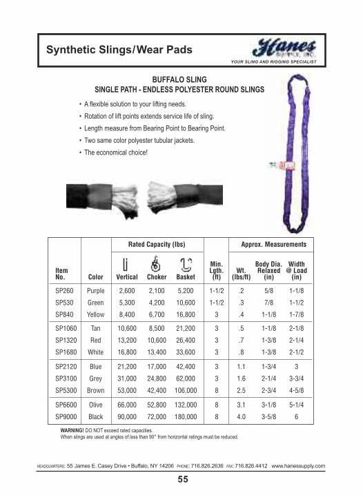
synthetic slings/Wear PadsYOUR SLING AND RIGGING SPECIALIST
55HEADQUARTERS: 55 James E. Casey Drive • Buffalo, NY 14206 PHONE: 716.826.2636 FAX: 716.826.4412 www.hanessupply.com
BUFFALO SLINGSINGLE PATH - ENDLESS POLYESTER ROUND SLINGS
• A flexible solution to your lifting needs.• Rotation of lift points extends service life of sling.• Length measure from Bearing Point to Bearing Point.• Two same color polyester tubular jackets.• The economical choice!
WARNING! DO NOT exceed rated capacities.When slings are used at angles of less than 90° from horizontal ratings must be reduced.
Rated Capacity (lbs) Approx. Measurements
Min. Body Dia. WidthItem Lgth. Wt. Relaxed @ LoadNo. Color Vertical Choker Basket (ft) (lbs/ft) (in) (in)
SP260 Purple 2,600 2,100 5,200 1-1/2 .2 5/8 1-1/8
SP530 Green 5,300 4,200 10,600 1-1/2 .3 7/8 1-1/2
SP840 Yellow 8,400 6,700 16,800 3 .4 1-1/8 1-7/8
SP1060 Tan 10,600 8,500 21,200 3 .5 1-1/8 2-1/8
SP1320 Red 13,200 10,600 26,400 3 .7 1-3/8 2-1/4
SP1680 White 16,800 13,400 33,600 3 .8 1-3/8 2-1/2
SP2120 Blue 21,200 17,000 42,400 3 1.1 1-3/4 3
SP3100 Grey 31,000 24,800 62,000 3 1.6 2-1/4 3-3/4
SP5300 Brown 53,000 42,400 106,000 8 2.5 2-3/4 4-5/8
SP6600 Olive 66,000 52,800 132,000 8 3.1 3-1/8 5-1/4
SP9000 Black 90,000 72,000 180,000 8 4.0 3-5/8 6

5.2 - MecHanIcal consIDeRatIons5.2.1 Use only if trained. Determine weight of the load. The weight of the load shall be within the
rated capacity of the sling.
5.2.2 Select the proper sling having suitable characteristics for the type of load, hitch and envi-ronment.
5.2.3 Slings shall not be loaded in excess of the rated capacity. Consideration should be given tothe angle of lift (sling-to-load angle), which affects rated capacity.
5.2.4 Slings with fittings which are used in a choker hitch shall be of sufficient length to assure thatthe choking action is on the webbing, and never on the other fitting.
5.2.5 Slings used in a basket hitch shall have the load balanced to prevent slippage.
5.2.6 The opening in fittings shall be the proper shape and size to insure that the fitting will seatproperly in the hook or other attachments.
5.2.7 Slings shall always be protected from being cut by sharp corners, sharp edges, protrusionsor abrasive surfaces.
5.2.8 Slings shall not be dragged on the floor or over an abrasive surface.
5.2.9 Slings shall not be twisted or tied into knots, or joined by knotting.
5.2.10 Slings shall not be pulled from under loads when the load is resting on the sling.
5.2.11 Do not drop slings equipped with metal fittings.
5.2.12 Slings that appear to be damaged shall not be used unless inspected and accepted as usable under Section 5.2.
5.2.13 The sling shall be hitched in a manner providing control of the load.
5.2.14 Portions of the human body should be kept from between the sling and the load, and frombetween the sling and the crane hook or hoist hook.
5.2.15 Personnel should stand clear of the suspended load.
5.2.16 Personnel shall not ride the sling.
5.2.17 Shock loading should be avoided.
5.2.18 Twisting the legs (branches) shall be avoided.
5.2.19 Load applied to the hook should be centered in the base (bowl) of hook to prevent pointloading on the hook.
5.2.20 During lifting, with or without the load, personnel shall be alert for possible snagging.
5.2.21 The slings' legs (branches) should contain or support the load from the sides above the center of gravity when using a basket hitch.
5.2.22 Slings shall be long enough so that the rated load (rated capacity) is adequate when theangle of the legs (branches) is taken into consideration.
HEADQUARTERS: 55 James E. Casey Drive • Buffalo, NY 14206 PHONE: 716.826.2636 FAX: 716.826.4412 www.hanessupply.comHEADQUARTERS: 55 James E. Casey Drive • Buffalo, NY 14206 PHONE: 716.826.2636 FAX: 716.826.4412 www.hanessupply.com
56
synthetic Web slingsYOUR SLING AND RIGGING SPECIALIST

5.3 - enVIRonMental consIDeRatIons5.3.1 Slings should be stored in a cool, dry and dark place, and should not be exposed to sunlight
or ultraviolet light, to prevent mechanical or chemical damage when not in use.
5.3.2 Chemically active environments can affect the strength of synthetic web slings in varying de-grees ranging from none to total degradation. The sling manufacturer should be consultedbefore slings are used in chemically active environments.a. acIDs
1. Nylon is subject to degradation in acids, ranging from none to total degradation.2. Polyester is resistant to many acids, but is subject to degradation, ranging from none
to moderate in some acids.3. Each application shall be evaluated, taking into consideration the following:
i Type of Acidii Exposure to conditionsiii Concentrationiv Temperature
b. alkalIs1. Polyester is subject to degradation in alkalis, ranging from none to total degradation.2. Nylon is resistant to many alkalis, but is subject to degradation ranging from none to
moderate in some alkalis.3. Each application shall be evaluated, taking into consideration the following:
i Type of Alkaliii. Exposure to conditionsiii Concentrationiv Temperature
5.3.3 Nylon and polyester slings shall not be used at temperatures in excess of 194°F (90°C),however, they may be used in temperatures as low as -40°F (-40°C).
5.3.4 Slings incorporating aluminum fittings shall not be used where fumes, vapors, sprays, mistsor liquids of alkalis and/or acids are present.
5.3.5 Environments in which synthetic webbing slings are continuously exposed to ultra-violetlight can affect the strength of synthetic webbing slings in varying degrees ranging fromslight to total degradation.a. Factors which affect the degree of strength loss are:
1. Length of time of continuous exposure2. Sling construction and design3. Other environmental factors such as weather conditions and geographic location.
b. Suggested procedures to minimize the effects of ultra-violet light1. Store slings in a cool, dry and dark place when not being used for prolonged periods
of time2. Inspect slings weekly or more often depending on frequency of sling use
c. Visual indications of ultra-violet degradation are:1. Bleaching out of sling color2. Increased stiffness of sling material3. Surface abrasion in areas not normally in contact with the load.
d. Proof-Testing – Slings used in environments where they are subject to continuous exposure to ultra-violet light should be proof-tested to two times rated capacity annually, or more frequently depending on severity of exposure.
HEADQUARTERS: 55 James E. Casey Drive • Buffalo, NY 14206 PHONE: 716.826.2636 FAX: 716.826.4412 www.hanessupply.com
57
synthetic Web slingsYOUR SLING AND RIGGING SPECIALIST

synthetic Web slingsYOUR SLING AND RIGGING SPECIALIST
58HEADQUARTERS: 55 James E. Casey Drive • Buffalo, NY 14206 PHONE: 716.826.2636 FAX: 716.826.4412 www.hanessupply.com HEADQUARTERS: 55 James E. Casey Drive • Buffalo, NY 14206 PHONE: 716.826.2636 FAX: 716.826.4412 www.hanessupply.com
5.4 - InsPectIon5.4.1 tYPe of InsPectIon
a. InItIal InsPectIon – Before any new or repaired sling is placed in service, it shall be inspected to insure that the correct sling is being used, as well as to determine that the sling meets the requirements of this specification.
b. fReQUent InsPectIon – This inspection should be made by the person handling the sling each time the sling is used.
c. PeRIoDIc InsPectIon – This inspection shall be conducted by designated personnel. Frequency of inspection should be based on:1. Frequency of sling use2. Severity of service conditions3. Experience gained on the service life of slings used in similar applications4. Periodic inspections should be conducted at least monthly
5.5 - PossIble Defects5.5.1 A sling shall be removed from service if any defects such as the following are visible:
a. Acid or alkali burnsb. Melting, charring, or weld spatter of any part of the slingc. Holes, tears, cuts, snags or embedded particlesd. Broken or worn stitching in load bearing splicese. Excessive abrasive wearf. Knots in any part of the slingg. Distortion and excessive pitting or corrosion or broken fittingsh. Other apparent defects which cause doubt as to the strength of the slingi. If sling rated capacity or sling material identification is missing or not readable
5.6 - InsPectIon RecoRDs5.6.1 Written inspection records, utilizing the identification for each sling as established by
the user, should be kept on file for all slings. These records should show a description of the new sling and its condition on each subsequent inspection.
5.7 - RePaIR of Web slInGs5.7.1 Slings shall be repaired only by a sling manufacturer. When repaired by other than the
original manufacturer, the sling shall be permanently marked to identify the repair agent.
5.7.2 All repaired slings shall be proof-tested to two (2) times its newly assigned rated capacity, berfore being put back into service. Certification of proof-test should be provided.
5.7.3 Temporary repairs of either webbing, fittings, or stitching shall not be permitted.

stRaP enDlenGtH HaRDWaRe Wll
27' 1015 3,335 lbs.30' Flat Hook 1515 kgs.
27' 3705-2 3,335 lbs.Chain Anchor 1515 kgs.
27' 1006 3,335 lbs.Wire Hook 1515 kgs.
TRUCKER TIE DOWN AND LASHING EQUIPMENT
RATCHET STRAPS— Designed to handle most types of flatbed tie-down requirements. • All straps have an 18" fixed end as standard, except for straps with 3705-2 and 3705-3chain anchors which have a fixed end of 30". Special length fixed ends and alternate endhardware available through Hanes Supply.Labeled to meet CVSA guidelines, DOT regulations and WSTDA recommended standards.
2" RATCHET STRAP W/804 WIDE HANDLE AND 2004 WEBBING
3" RATCHET STRAP W/806 LONG HANDLE AND 3004 WEBBINGstRaP enD
lenGtH HaRDWaRe Wll27' 1021-3 5,000 lbs.30' Flat Hook 2270 kgs.
stRaP enDlenGtH HaRDWaRe Wll
27' 3705-3 5,400 lbs.30' Chain Anchor 2450 kgs.27' 3704 5,400 lbs.30' Grab Hook 2450 kgs.
15,000 LB. BREAKING STRENGTH
16,200 LB. BREAKING STRENGTH
stRaP enDlenGtH HaRDWaRe Wll
27' 1021-3 5,000 lbs.30' Flat Hook 2270 kgs.
stRaP enDlenGtH HaRDWaRe Wll
27' 1016 6,600 lbs.30' Wire Hook 2995 kgs.
15,000 LB. BREAKING STRENGTH
20,000 LB. BREAKING STRENGTH
4" RATCHET STRAPW/808 LONG HANDLE AND 4004 WEBBING
10,000 LB. BREAKING STRENGTH
59
Polyester Ratchet assemblyYOUR SLING AND RIGGING SPECIALIST
HEADQUARTERS: 55 James E. Casey Drive • Buffalo, NY 14206 PHONE: 716.826.2636 FAX: 716.826.4412 www.hanessupply.com

60HEADQUARTERS: 55 James E. Casey Drive • Buffalo, NY 14206 PHONE: 716.826.2636 FAX: 716.826.4412 www.hanessupply.com HEADQUARTERS: 55 James E. Casey Drive • Buffalo, NY 14206 PHONE: 716.826.2636 FAX: 716.826.4412 www.hanessupply.com
stRaP assY.lenGtH enD bReakInG
(ft) HaRDWaRe stRenGtH Wll12 Series E, A
16FE8306-1 3,000 lbs. 1,000 lbs.
20Spring 1360 kgs. 455 kgs.Fitting
12 Series E, A
1643020-1 3,000 lbs. 1,000 lbs.
203-Piece 1360 kgs. 455 kgs.Fitting
12 Series F
161831 1,250 lbs. 420 lbs.
20Butterfly 570 kgs. 195 kgs.Fitting
12 Series F
16FE8427-1 2,200 lbs. 735 kgs.
20Plate Trailer 1000 kgs. 335 kgs.
Hook
2" LOGISTIC STRAPS W/811 RATCHET BUCKLE AND 4900 WEBBING
LOGISTIC STRAPS — Designed for interior van loading requirements.• All straps have a 4' fixed end as standard.• Adjustable ends are sewn captivated.
710987 - 9'
RATCHET STRAP WITH 800 RATCHET AND VINYL COATED S HOOKS• Breaking Strength: 1,200 lbs. • WLL: 400 lbs.
STRAP-ALL™ STRAPS — Light duty tie-down
711681/45 - 16'
RATCHET STRAP WITH 800 RATCHET, WIRE HOOKS AND D RINGS• Breaking Strength: 2,500 lbs./1135 kgs. • WLL: 835 lbs./380 kgs.
TRUCKER TIE DOWN AND LASHING EQUIPMENT
Polyester Ratchet assemblyYOUR SLING AND RIGGING SPECIALIST

load bindersYOUR SLING AND RIGGING SPECIALIST
61
• Follow OSHA, ASME B30.9 & Manufacturer’s Guidelines.• Use only if trained.• Failure to use this load binder properly may result in seriousinjury or even death.
• Do not operate load binder while standIng on the load.• Move handle with caution. It may whip – Keep body clear.• Keep yourself out of the path of the moving handle.• You must be familiar with state and federal regulations regarding size and number of chain systems required for securing loads on trucks.
• Always consider the safety of nearby workers as well asyourself when using load binder.
• While under tension, load binder must not bear against anyobject.
• Do not thow these instructions away. Keep them close athand & share them with any others who use this load binder.
INSTRUCTIONS - LEVER TYPE LOAD BINDERS• Hook load binder to chain so you can operate it while standing on the ground.Position load binder so its handle can bepulled downward to tighten chain (seephoto). Be aware of ice, snow rain, oil, etc. that canaffect your footing. Make certain your footing is secure.
• The Crosby Group, Inc., specifically recommends AGAINSTthe use of a handle extender (cheater pipe). If sufficient lever-age cannot be obtained using the lever type load binder by itself, a ratchet type binder should be used.
• If the above recommendation is disregarded and a cheaterpipe is used, it must closely fit the handle and must slide downthe handle until the handle projections are contacted. The pipeshould be secured to the handle, for example, by a pin, sothat the pipe cannot fly off the handle if you lose control andlet go. The increased leverage, by using a cheater pipe, cancause deformation and failure of the chain and load binder.
• During and after tightening chain, check load binder handleposition. Be sure it is in the locked position and that its bot-tom side touches the chain link.
• Chain tension may decrease due to load shifting during trans-port. To be sure the load binder remains in proper position:Secure handle to chain by wrapping the loose end of chainaround the handle and the tight chain, or tie handle to chainwith soft wire.
• When releasing load binder, remember there is a great deal ofenergy in the stretched chain. This will cause the load binderhandle to move very quickly with great force when it is unlatched. Move handle with caution. It may whip – Keepbody clear.
• Never use a cheater pipe or handle extender to releasehandle. Use a steel bar and pry under the handle and stayout of the path of handle as it moves upward.
• If you release the handle by hand, use an open hand underthe handle and push upward. Do not close your handaround the handle. Always keep yourself out of the pathof the moving handle.
INSTRUCTIONS - RATCHET LOAD BINDERS• Position ratchet binder so it can be operated from the ground.• Make sure your footing is secure.MAINTENANCE OF ALL LOAD BINDERS• Routinely check load binders for wear, bending, cracks, nicks,or gouges. If bending or cracks are present – Do not useload binder.
• Routinely lubricate pivot and swivel points of Lever Binders,and pawl part and screw threads of Ratchet Binders to extendproduct life and reduce friction wear.
LOAD BINDER WARNINGS AND APPLICATION INSTRUCTIONS
RATCHET TYPE
LOAD BINDER WARNINGS AND APPLICATION INSTRUCTIONS
LEVER TYPE
LEVER SNUBBING TYPE LEVER WALKING TYPE
LEVER RELEASING TYPE
Mechanical AdvantageLever Type Binder = 25:1Ratchet Type Binder = 50:1Example: 100 pounds of effort applied to the binder results inthe following force on the binder.Lever Type:2500 (100 lbs. x 25) lbs. of forceRatchet Type:5000 (100 lbs. x 50) lbs. of force
WARNING!
HEADQUARTERS: 55 James E. Casey Drive • Buffalo, NY 14206 PHONE: 716.826.2636 FAX: 716.826.4412 www.hanessupply.com

stanDaRD leVeR tYPe loaD bInDeRsl-150
RatcHet tYPe loaD bInDeR
MIn-MaX WoRkInG MInIMUMcHaIn loaD PRoof UltIMate WeIGHt HanDle take
stock stD. sIze lIMIt loaD stRenGtH eacH lenGtH UPMoDel no. PkG. (In.) (lbs.) (lbs.) (lbs.) (lbs.) (In.) (In.)
7-1 1048128 4 5/16-3/8 5400 10800 19000 7.02 16.00 4.50A-1 1048146 4 3/8-1/2 9200 18400 33000 12.47 18.69 4.50C-1 1048164 4 1/2-5/8 13000 26000 46000 19.68 21.00 4.75
• Forged Steel–Quenched & Tempered.• Binder toggles away from the load.
WoRkInG aPPRoX.MaX loaD lIMIt PRoDUct UPc take-UP WeIGHt
sIze (In.) (lbs.) coDe 43927- (In.) eacH (lbs.)
3/8 G80, G43 7,100 D48360 81767- 8 135/8 G70 48360 1/2 G70 13,000 D48367 30008 8 145/8 G43
• Heavy duty, rigid, all steel construction.• Short reach hooks for maximum take-up.• Infinite adjustment.• Continuous take-up.• Meets DOT and CVSA specifications.
cHaIn sIze cHaIn WoRkInG loaD PRoDUct HanDle take-UP WeIGHt(In.) GRaDe lIMIt (lbs.)* coDe lenGtH (In.) (In.) (lbs.)
3/8 30,43,70,80 7,100 D48769 16 4-7/8 8-1/4
3/8" leVeR tYPe loaD bInDeR• Provides more control in binding and releasing without extra tools.• Handle closes down away from load with more leverage.• Hooks are heat treated steel.• Functionally superior to any other on the road.• Handles are drop forged from special bar quality steel.• Single welded links as in binder chain for better reliability. • More take-up for binding greater loads. Smaller handle slot with
riveted nose to prevent spreading at the critical loading point.• Meets DOT and CVSA requirements.
HEADQUARTERS: 55 James E. Casey Drive • Buffalo, NY 14206 PHONE: 716.826.2636 FAX: 716.826.4412 www.hanessupply.comHEADQUARTERS: 55 James E. Casey Drive • Buffalo, NY 14206 PHONE: 716.826.2636 FAX: 716.826.4412 www.hanessupply.com
62
load bindersYOUR SLING AND RIGGING SPECIALIST

MIn-MaX WoRkInG DIMensIons (In.)cHaIn loaD UltIMate WeIGHt take
l-130 sIze lIMIt loaD eacH UPMoDel stock no (In.) (lbs.) (lbs.) (lbs.) (In.) a b c D e f G
W-1 1048100 3/16-1/4 1450 5100 2.57 2.40 13.63 16.13 11.00 11.25 6.25 6.58 .34
l-140
stanDaRD RatcHet tYPe loaD bInDeR
l-130 MIDGet loaD bInDeR
note: Binders shown with Proof Load Pounds have been individually Proof Tested to these values shown, prior to shipment.* Ultimate Load is 3 times the Working Load Limit.
** Matches the Working Load Limit of Grade 100 chain for both sizes.***Matches the Working Load Limit of Grade 100 chain for 1/2" size.
• Upgrade for use with Grade 7 Transport Chain - applies to R-7 only.• Utilizes standard Crosby A-323 Alloy Eye Grab Hooks.• New design "one piece" forged handle.• Continuous take-up feature, infinite adjustment, gets the last half of chain.• One piece assembly, no bolts or nuts to loosen.• Ratchet spring rust proofed.• All load bearing or holding parts forged.• Easy operating positive ratchet.• Meets or exceeds CVSA Cargo Securement Guidelines, August 1993.
• Forged handle, hooks and swivel link.• Steel swivels and clevis.• Meets or exceeds DOT and CVSA Cargo Securement Tie-Down Guidelines, November 2003.
G
E1 OPENE CLOSED C
A
A
B
C
D
E
F
G
B
F1 OPENF CLOSED
HEADQUARTERS: 55 James E. Casey Drive • Buffalo, NY 14206 PHONE: 716.826.2636 FAX: 716.826.4412 www.hanessupply.com
63
load bindersYOUR SLING AND RIGGING SPECIALIST
MODEL STOCK NO.
MIN-MAXCHAINSIZE(IN)
WORKINGLOADLIMIT(LBS)
PROOFLOAD(LBS)
MINIMUMULTIMATESTRENGTH
(LBS)
WEIGHTEACH(LBS)
HANDLELENGTH(IN)
TAKEUP(IN)
DIMENSIONS (IN)
A B C E E1 F F1 G
R-7 ** 1048404 5/16 - 3/8 8800 17600 12.11 14 10 8.0 14.00 1.38 2.75 22.94 30.94 25.13 33.13 .50R-A ** 1048422 3/8 - 1/2 15000 30000 14.70 14 10 8.0 14.00 1.38 2.75 25.25 33.25 27.63 35.63 .63R-C *** 1048440 1/2 - 5/8 16000 32000 14.55 14 10 8.0 14.00 1.38 2.75 26.38 34.38 29.44 37.44 .72

transport chain (Binding Chain)YOUR SLING AND RIGGING SPECIALIST
64HEADQUARTERS: 55 James E. Casey Drive • Buffalo, NY 14206 PHONE: 716.826.2636 FAX: 716.826.4412 www.hanessupply.com HEADQUARTERS: 55 James E. Casey Drive • Buffalo, NY 14206 PHONE: 716.826.2636 FAX: 716.826.4412 www.hanessupply.com
GRADE 70 TRANSPORT (BINDING) CHAIN• Meets ASTM & NACM standard• Meets FMCSA & CVSA requirements• Thermal Heat treated using advanced technologies• Heat treated for superior wear & toughness• 100% proof tested• Permanent identification on chain
BINDING CHAIN SPECIFICATIONSThis chart indicates the minimum number of chains required to secure loads in the forward direction (0.8g deceleration)* per federal Motor Carriers Safety Administration, DOT Regulations; per 49CFR, Part 393 - Paragraph 393.102.*Refer to 49CFR, Parts 392 and 393, for North American Standard for Protection Against Falling & Shifting Cargo for complete regulations.
CHAINSIZE WLL
PRODUCT CODE
A B C APP.WEIGHT
APPNO. OFLINKS
DRUM PACK CODE NO. (YELLOW CHROMATE FINISH)
SELFCOLORED
YELLOWCHRO-MATE
THERMALDIPPEDBLACK
FULLDRUM LENGTH HALF
DRUM LENGTH PAIL LENGTH
(IN) (LBS) (IN) (IN) (IN) (LB/FT) (PER FT) (FT) (FT) (FT)
1/4 3,150 608926 608927 - 0.281 0.840 0.470 0.76 14.3 678531 800 678521 400 678517 130
5/16 4,700 608936 608935 - 0.327 0.980 0.460 1.01 12.2 678532 550 678522 275 678518 90
5/16 4,700 609036 609035 - 0.327 1.100 0.500 0.97 10.9 679022 550 679022 275 679018 90
3/8 6,600 608940 608941 - 0.406 1.140 0.540 1.58 10.5 678523 400 678523 200 678519 60
3/8 6,600 609940 609040 - 0.394 1.375 0.600 1.39 8.73 679023 400 679023 200 679019 60
7/16 8,750 608946 608947 - 0.468 1.325 0.620 2.09 9.06 678524 300 678524 150 - -
1/2 11,300 608953 608954 - 0.531 1.730 0.750 2.56 6.94 678525 200 678525 100 9704850 40
MIN # OF CHAINS REQUIRED TO SECURE LOADS IN FORWARDDIRECTION BY WEIGHT OF THE ARTICLE IN LBS (kN)
CHAINGRADE SIZE
WORKINGLOAD LIMIT
5,000(22)
10,000(44)
15,000(67)
20,000(89)
25,000(111)
30,000(133)
35,000(156)
40,000(178)
45,000(200)
50,000(222)
(IN) (LBS) (kN)
GRADE 30PROOF COIL
5/16 1,900 8 3 5 7 9 11 13 15 17 19 223/8 2,650 12 2 4 5 7 8 10 11 13 14 16
GRADE 43HIGH TEST
5/16 3,900 17 2 3 4 5 6 7 8 9 10 113/8 5,400 24 1 2 3 3 4 5 6 6 7 8
GRADE 70TRANSPORT
1/4 3,150 14 2 3 4 6 7 8 9 11 12 135/16 4,700 21 1 2 3 4 5 6 6 7 8 93/8 6,600 29 1 2 2 3 4 4 5 5 6 7
GRADE 80ALLOY
7/32 2,100 9 2 4 6 8 10 12 14 16 18 209/32 3,500 16 2 3 4 5 6 7 9 10 11 125/16 4,500 20 1 2 3 4 5 6 7 8 9 103/8 7,100 32 1 2 2 3 3 4 4 5 6 6
GRADE 100 ALLOY 3/8 8,800 39 1 1 2 2 3 3 4 4 5 5

Manual Hoists - PullersYOUR SLING AND RIGGING SPECIALIST
65
optional loadsecurity
3/4 ton Pullershown Also availablein 1-1/2, 3 & 6ton capacity
• Free wheeling for fast and easy attach-ment to load.
• Upper and lower Latchlok hooks availablefor all capacities.
• Optional Load Limiter protection devicestops transmission of lever forces protect-ing against dangerous overload.
• Optional anchor sling simplifies attachmentto allow anchor hook to swivel in tight spaceapplications (3/4 & 1-1/2 ton units only).
• Optional Load Sentry warns of overloadcondition.
• Optional shorter lever for 3/4 and 1-1/2 tonunits available.
• Optional zinc-plated chain available.• Unlimited lift.• Lifetime warranty.• Made in U.S.A.
cM Puller is designed for heavy-duty con-struction and industrial applications. Used topull, lift, drag or stretch, it features:• Tough aluminum alloy construction and
powder coat finish.• Weatherproof for outdoor service.• Simple construction with fewer parts for
ease of maintenance.• Hoistaloy hardened steel link type load
chain for strength, long wear life and flexi-bility.
• Weatherized Weston-type automatic brak-ing system for positive load control.
• Easy, one-hand operation and control —only 58 pounds of pull required for 3/4 tonmodel capacity.
• Forged upper and lower hooks withlatches standard.
• Free chaining for fast, easy attachment toload.
• Forged upper and lower hooks with latches.• Simple construction with fewer parts for
ease of maintenance.• Optional Load Limiter® device protects
against overload• Lifetime warranty• Made in U.S.A.
• Easy one-hand operation.• Lever pull range is 45 to 62 pounds to lift
full load.• Handle that rotates 360O, making it easy
to operate in any position and in smallspaces.
• Tough yet lightweight aluminum construc-tion and powder coat finish.
• CM® Hoistaloy® hardened steel load chainfor strength, long wear life and flexibility.
cM PUlleR
cM sHoRt HanDle PUlleR
PUll to MInIMUM Hook aPPRoX.RateD stD. lIft fUll DIstance leVeR tHRoat sHIPPInG
caPacItY PRoD. lIft† loaDs betWeen lenGtH oPenInGs WeIGHt(tons) coDe (ft) (lbs) Hooks (In) (In) ReeVInG (In) (lbs)
3/4 4043 5 58 10-3/4 21-1/4 1 1-1/32 161-1/2 4045 5 89 14-1/4 21-1/4 1 1-1/8 16
3 4047 5 95 16-15/16 21-1/4 2 1-7/32 386 4050 5 96 21-3/8 21-1/4 4 1-3/4 73
† Can be supplied with lifts longer than 5 feet
PUll to Hook MIn. aPPRoX.RateD stD. lIft fUll leVeR tHRoat DIstance sHIPPInG
caPacItY PRoDUct lIft loaD lenGtH oPenInG betWeen Wt.(tons) coDe (ft) ReeVInG (lbs) (In.) (In) Hooks (In) (lbs)
3/4 7300P 5 1 45 12 1-1/32 12-1/4 161-1/2 7320P 5 1 55 16-3/4 1-1/8 14-3/4 27
3 7330P 5 2 62 16-3/4 1-3/16 17-5/8 40
optional loadlimiter
latchloktypehook
optionalanchorsling(3/4 & 1-1/2ton)
3/4 ton Pullershown
Also availablein 1-1/2 & 3 ton
capacity
Optional kits also available - Load Limiter, Anchor Sling & Latchlok® Hook.Call Hanes Supply for complete details.
HEADQUARTERS: 55 James E. Casey Drive • Buffalo, NY 14206 PHONE: 716.826.2636 FAX: 716.826.4412 www.hanessupply.com

Hand chain HoistsYOUR SLING AND RIGGING SPECIALIST
66HEADQUARTERS: 55 James E. Casey Drive • Buffalo, NY 14206 PHONE: 716.826.2636 FAX: 716.826.4412 www.hanessupply.com HEADQUARTERS: 55 James E. Casey Drive • Buffalo, NY 14206 PHONE: 716.826.2636 FAX: 716.826.4412 www.hanessupply.com
cM cYclone HanD cHaIn HoIstOne of the most popular and reliable hoistsever designed, the CM Cyclone combinessuperior engineering, efficiency and durabil-ity. Available in a variety of capacities from1/4 ton to 10 tons, CM Cyclone features:• Most interchangeability of parts in the
industry.• Standard Load Limiter for simple,
automatic overload protection.• Enclosed contoured Weston-type auto-
matic brake for positive load control.• High-efficiency spur gearing for greater
lift with minimum effort.• Rugged CM Hoistaloy chain for added
strength and durability.• Fully machined, forged liftwheel pickets
for easier lifting and smooth free chaining.• High-strength aluminum alloy castings in
frame and covers.
MInIMUM cHaInRateD stanDaRD DIstance oVeRHaUleD cHaIn PUll sHIPPInG
caPacItY PRoDUct lIft † betWeen to lIft loaD to lIft fUll WeIGHt(tons) coDe (ft.) ReeVInG Hooks (In.) one foot (ft.) (lbs.) (lbs.)
1/4 4621 8 1 12-7/8 22-1/2 23 371/2 4622 8 1 12-7/8 22-1/2 46 371 4624 8 1 14 30 69 40
1-1/2 4625 8 1 17-5/16 40-1/2 80 652 4626 8 1 17-5/16 52 83 643 4627 8 2 21-1/2 81 85 964 4628 8 3 21-1/2 104 88 965 4629 8 3 24-1/4 156 75 1286 4630 8 3 25-1/4 156 90 1328 4631 8 4 34-1/2 208 89 235
10 4632 8 5 35-1/2 260 95 249† Can be supplied with longer lifts
• Inspected over 75 times to meet or ex-ceed HMI and ASME/ANSI performanceand safety standards.
• Standard hand chain drop is 2 feet lessthan lift, (example: 8 foot lift hoist has 6foot hand chain drop).
• Chain containers, zinc-plated load andhand chain, aluminum unwelded handchain, Latchlok hooks, bronze hooks,eye-type suspension, bullard hooks and units without Load Limiter optional,depending on capacity.
• Lifetime warranty.• Made in U.S.A.
3 and 4 toncapacity
5 and 6 toncapacity
8 toncapacity
10 toncapacity
1/4 to 2 toncapacity
Hanes supply 25 toncapacity test stand

HEADQUARTERS: 55 James E. Casey Drive • Buffalo, NY 14206 PHONE: 716.826.2636 FAX: 716.826.4412 www.hanessupply.com
Harrington HoistsYOUR SLING AND RIGGING SPECIALIST
67
CAP (TON
S)
PROD
UCT C
ODE
STD LIFT (FT)
PUSH BUTTON
CORD L (FT)
LIFTING SPEED
(FT/MIN)
LIFTING MOTOR1 PHASE 60 Hz
LOAD CHAIN DIA (M
M)x C
HAIN FA
LL INES
NET WEIGH
T(LBS)
WEIGH
T FOR ADD’L
1' OF LIFT (LBS)
OUTPUT(Hp)
RATED CURRENT(AMPS)
@ 115V @ 230V
1/4 SNER003S
107.2
140.34 7.7 3.9
5.0 x 1 82 0.371/2 SNER005L 7 6.3 x 1 84 0.571/2 SNER005S 15
0.6 16.9 8.56.3 x 1 104 0.57
1 SNER010L 7 8.0 x 1 110 0.931 SNER010S 14
1.2 23.9 12.08.0 x 1 159 0.93
2 SNER020L 7 10.0 x 1 174 1.53 SNER030C 8.2 3.5 10.0 x 2 207 3.1
CAP (TON
S)
PROD
UCT CO
DE
HEADRO
OM C (IN)
STANDARD LIFT (FT)
PULL TO
LIFT LO
AD(LBS) A
(IN)B(IN)
D(IN)
E(IN)
F(IN)
G(IN)
LOAD CHAIN DIA (M
M)x C
HAIN FA
LL INES
NET WEIGH
T (LBS)
SHIPPING
WEIGH
TAPPROX
(LBS)
WEIGH
T FOR ADD’L
1' OF LIFT (LBS)
3/4 LB00811.0
5
586.0 4.8 10.4" 4.0 1.4 0.9 5.6 x 1 14 14 0.4
1 LB010 771-1/2 LB015
13.858
6.7 5.6
16.3
4.3 1.8 1.3 7.1 x 1 21 22 0.82 LB020 773 LB030 16.5 70
7.77.0
4.52.0 1.6 9.0 x 1 34 36 1.2
6 LB060 22.4 72 8.7 2.4 2.0 9.0 x 2 60 62 2.49 LB090 27.8 74 11.1 3.9 2.9 9.0 x 3 93 97 3.6
LB LEVER MANUAL HOISTSHarrington LB Lever Hoists combine easy operation with a compact, reliable design that easily handles the real-world demands of contractor and industrial applications. Examples include day-to-daymaintenance, machine repair, construction, service, and manufacturing operations. You’ll find every job goeseasier thanks to smooth, reliable lifting and pulling actions. Compact size and easy operation make the LBlever puller the “cumalong to take along” wherever you have a load to move.
SNER ELECTRIC CHAIN HOISTSHarrington’s SNER Series of electic chain hoists and SMR motorized trolleys offer expanded duty,low headroom and additional capacities for those many applications where only single-phase power is available. The standard features of the popular three-phase NER/MR Series are incorporated to provide the operator with top quality and high performance.
STANDARD FEATURES• 1/4 – 3 Ton capacities• Low headroom• Lightweight and easy maintenance• Pull-rotor motor brake• ASME H4 classification• NEMA 3R IP55 rating
TOP QUALITY HOISTS• 60 minute service duty rating(fan cooled)
• Unique long life chain guide• Friction clutch preventslifting/lowering slippage
• Single chain fall through 2 Tons
APPLICATIONS• Machine shops• Temporary job sites• Maintenance area

Powered chain HoistsYOUR SLING AND RIGGING SPECIALIST
68HEADQUARTERS: 55 James E. Casey Drive • Buffalo, NY 14206 PHONE: 716.826.2636 FAX: 716.826.4412 www.hanessupply.com HEADQUARTERS: 55 James E. Casey Drive • Buffalo, NY 14206 PHONE: 716.826.2636 FAX: 716.826.4412 www.hanessupply.com
The balanced, integrated, proven design of the Lodestarhas made it the most popular electric chain hoist in the industry. Lodestar gives you more value for your money including:• Up to 3 ton capacities for heavy-duty industrial applica-
tions.• Gear train lifetime lubricated with non-oxidizing grease.• Precision machined and hardened liftwheel with hard-
ened chain guides for precise chain liftwheel fit.• Grearing designed for exceptionally long life and quiet
operation.• H4 duty standard.• Rugged control station (NEMA 4).• Hoist duty motor, standard Protector overload device
and standard screw type limit switches.• Hardened, forged steel, latch type hooks and Hoistaloy
load chain for long, dependable service.• Easy to install and maintain.
cM loDestaR electRIc cHaIn HoIst• No special tools required to disassemble.• High reliability and long life.• Designed for greater productivity, efficiency
and economy.• Lifetime warranty.• Each hoist thoroughly inspected and tested to over
125% of rated load prior to shipment.• Meets ASME B30.16.• Made in U.S.A.
special applications• Harsh environment hoists available for severe duty of
plating, galvanizing and washdown applications.• Hoists with climbing capability available for temporary
rigging of lifting applications – must be used in invertedposition only.
• Hoists with creep control allow precise positioningthrough field adjustment within the range of approxi-mately 1/16" to 1/2".
Hooksuspension
Motorized
Plain trolley

cordage InformationYOUR SLING AND RIGGING SPECIALIST
69
Select the Correct SizeA rope too small may fail quickly, one too large will prove expensive. Don't work any ropeabove one-fifth of its breaking strength.
Avoid OverloadsSafe working load ranges for any new rope is between 1/5 and 1/12 of its minimum tensile.Make enough allowances for safety if your rope is old or worn. Ignoring this safety factorcauses early rope replacement and is dangerous to men and materials.
Keep Away from ChemicalsAcids & Alkalis are injurious to rope. If exposed, wash thoroughly and inspect before using.Watch for battery and building cleaning acids, caustic soda and paint. Keep rats away.
Stop Unnecessary WearOuter and inner rope fibers contribute equally to the strength of your rope. If worn out, therope is naturally weakened. Eliminate rubbing, dragging or working over rough surfaces. Protect its surface with chafing gear, such as canvas wrapped and tied around the rope. Pad corners of sharp objects when lifting, and avoid strain on sharp bends. Remove kinks if they form.
To Uncoil RopeA new coil of rope should be placed flat on its side with the "tag" inside end down. Removethe outside lashings and unfasten the inside bands. Leave burlap around the coil to keeprope clean. Reach down through the eye of coil and pull out the inside end, where tag is attached,through the eye of the coil.
Store it ProperlyKeep in dry, cool place with good air circulation. Use wooden grating on concrete or steelfloors, and keep away from steam pipes and metal walls. Protect from prolonged exposureto sunlight. Store only clean, dry rope.
Use Right SheavesBlock sizes or sheaves should be eight times the diameter of the rope. For power transmis-sion or for use with continuous load, sheaves should be at least forty times the diameter ofthe rope. Small sheaves cause added friction and rope wear. Keep sheaves smooth.
Watch Rope ConditionInspect rope frequently, whether working or in storage. Occasionally reverse your rope, end-to-end, to distribute the wear more evenly.Use worn rope only where strength failure will not cause injury or damage.
*All ropes will last longer if given proper care and handling, storage and use. These are the more important points to keep in mind to assure greatest service and safety.
HEADQUARTERS: 55 James E. Casey Drive • Buffalo, NY 14206 PHONE: 716.826.2636 FAX: 716.826.4412 www.hanessupply.com

Rope Construction Selection Guide*Characteristics Solid Braid Hollow Braid Double Braid Diamond Braid Twisted
No. of Strands or Carriers 9, 12 or 18 8, 12 or 16 16, 24 or 32 8 or 16 3Spliceable No Yes Yes No YesStrength to Weight 5 2 1 4 3Flexibility 3 1 2 4 5Flattens Under Load No Yes No Yes NoRotates Under Load No No No No YesMechanical Elongation 1 4 5 3 2Cost Per Size 2 4 1 3 5Working Load (as a % of Tensile) 15-20% 15-20% 15-20% 15-20% 8-14%Abrasion Resistance 1 5 2 3 4WARNING: This guide is designedfor general reference only. The con-struction comparisons assume usingthe same rope fiber and size. Expertadvice should be sought whenchoosing a rope where protection of life or property is involved.
TopView
TopView
TopView
TopView
TopView
cordage InformationYOUR SLING AND RIGGING SPECIALIST
70HEADQUARTERS: 55 James E. Casey Drive • Buffalo, NY 14206 PHONE: 716.826.2636 FAX: 716.826.4412 www.hanessupply.com HEADQUARTERS: 55 James E. Casey Drive • Buffalo, NY 14206 PHONE: 716.826.2636 FAX: 716.826.4412 www.hanessupply.com
Solid or Single BraidThis construc-tion leaves avoid in the cen-ter and utilizesstrand countsof eight, 12 or16. The hollowis instrumentalin making iteasy to splice.Hollow braidsare nonrotatingand are an extremely efficient way to utilize fiber.
Plaited or HollowRopeEight-strand“Square Braid”is comprised ofeight individualstrands, whichare woven together as fourpairs. Its majoradvantages arenon-rotation &high energy absorption.
Double BraidThis is really twoseparate ropesin one: the core,which is a singlebraid, is over-braided with asleeve. This con-struction allowsthe rope to beused for moreapplications; thesame or dissimi-lar fibers can beengineered intoa rope suited toany of manyspecific applica-tions. This con-struction entirelyshields one ofthe two elementsin the rope fromabrasion.
Three-Strandor TwistedThe simplesttype of rope is formed bytwisting fiberinto a strand,and then twisting threestrands intorope. Its conversion efficiency isrelatively lowsince this constructiontechnique isthe hardest on fiber.

cordage InformationYOUR SLING AND RIGGING SPECIALIST
71
Rope Fiber Selection Guide: Fiber Properties - Typical Valu
es
Manila
Sisal
Cotton
Nylon
Polyester
Polyp
ropylen
ePolyethene
Kevlar1
Spectra
2
STRENG
TH:
Breaking Tenacity – Dry(gra
ms/de
nier)
Wet Stren
gth vs. Dry Stren
gthShock-load A
bsorp
tion A
bility
5.0 - 6
.0Up to 12
0%Poor
4.0 - 5.0
Up to 12
0%Poor
2.0 - 3
.0Up to 12
0%Very Poor
7.0 - 9
.585-90
%Excellent
7.0 - 9.5
100%
Good
6.5 100%
Very Go
od
6.0 100% Fair
5.0 - 6
.0Up to 12
0%Poor
5.0 - 6
.0Up to 12
0%Poor
WEIGH
T:Specific Grav
ityFlo
ats1.3
8No
1.38
No1.5
4No
1.14
No1.3
8No
0.91
Yes
0.95
Yes
1.44
No0.9
7No
ELON
GATIO
N:Perce
nt of Break
Creep (ext. u
nder susta
ined load)
10 - 1
2%Very Low
10 - 1
2%Very Low
5 - 12
%Very Low
18 - 2
5%Mo
derate
12 - 1
5%Low
15 - 2
5%High
15 - 2
5%High
1.5 - 3
.6%Very Low
3.5%
Moderate
EFFECTS OF MOISTURE:
Wate
r Absorp
. of In
div. Fibe
rsDiele
ctric Properties
Up to 10
0%Very Poor
Up to 10
0%Very Poor
Up to 10
0%Very Poor
2 - 8% Poor
<1%
Good
None
Excellent
None
Excellent
3.5 - 7
.0%Poor
None
Excellent
DEGR
ADATION:
Resistan
ce to UV Sunlight
Resistan
ce to Rot Milde
wStora
ge Requirem
ents
Good
Fair
Fair
Fair
Poor
Fair
Very Go
odExcellent
Excellent
Excellent
Good
Good
Good
Good
Fair
Fair
Very Go
odExcellent
THERMA
L PRO
PERTIES:
Melts at
Does Not
Melt
Chars
at 35
0°
Does Not
Melt
Chars
at 35
0°
Does Not
Melt
Chars
at 30
0°420 - 48
0°490 - 50
0°330°
275°
800° Begins
to Decom-
pose
297°
RESISTANCE
3 :Resistan
ce to Ac
idsResistan
ce to Alkalis
Resistan
ce to Oils & Gas
Poor
Poor
Poor
Poor
Poor
Fair
Poor
Fairr
Poor
Fair
Very Go
odVery Go
od
Good
Fair
Very Go
od
Excellent
Excellent
Very Go
od
Excellent
Excellent
Very Go
od
Fair
Fair
Very Go
od
Excellent
Excellent
Very Go
od* Black is b
est 1 - Based on
Dupont Kevlar
®Data 2 - Based on
Allied/S
igna; Spectra
®Data - Type 9
90
3 - Resistance is relative to the length
of ex
posure, percent of concentration &
temp
eratu
re.
HEADQUARTERS: 55 James E. Casey Drive • Buffalo, NY 14206 PHONE: 716.826.2636 FAX: 716.826.4412 www.hanessupply.com

NYLON ROPE• Four stage construction • High strength and elasticity• Medium-Soft Lay • Color: Natural White
DIA(IN)
NOMINAL STANDARDTENSILE(LBS)
MINIMUMTENSILE(LBS)
UNITS-SPOOL-(FT)
RWL5:1 - 12:1(LBS)
APPROX.DENSITY(LBS/100°)
SIZENO
DIA DECEQUIV.
1/4 3/4 0.250 1,650 1,490 600 298 - 124 1.55/16 1 0.313 2,550 2,300 600 460 - 192 2.53/8 1-1/8 0.375 3,750 3,340 600 668 - 278 3.41/2 1-1/2 0.500 6,400 5,750 600 1,150 - 479 6.55/8 2 0.625 10,000 9,000 600 1,800 - 750 10.03/4 2-1/2 0.750 14,200 12,800 600 2,560 - 1,067 14.57/8 2-3/4 0.875 20,000 18,000 600 3,600 - 1,500 20.01 3 1.000 25,000 22,600 600 4,520 - 1,883 26.0
1-1/8 3-1/2 1.125 32,000 28,800 600 5,760 - 2,400 32.51-1/4 3-3/4 1.250 37,500 33,800 600 6,760 - 2,817 40.01-1/2 4-1/2 1.625 53,000 47,800 600 9,560 - 3,983 55.01-5/8 5 1.500 65,000 58,500 600 11,700 - 4,875 66.5
2 6 2.000 92,000 83,000 600 16,600 - 6,917 95.02-1/4 7 2.250 125,000 113,000 600 22,600 - 9,417 129.02-1/2 7-1/2 2.500 140,000 126,000 600 25,200 - 10,500 149.02-5/8 8 2.625 162,000 146,000 600 29,200 - 12,167 168.0
3 9 3.000 200,000 180,000 600 36,000 - 15,000 210.04 12 4.000 360,000 324,000 600 64,800 - 27,000 379.0
POLYESTER ROPE• Continuous multifilament yarn • Good abrasion resistance• Low stretch • Color: Natural White • Excellent UV resistance
DIA(IN)
NOMINAL STANDARDTENSILE(LBS)
MINIMUMTENSILE(LBS)
UNITS-SPOOL-(FT)
RWL5:1 - 12:1(LBS)
APPROX.DENSITY(LBS/100°)
SIZENO
DIA DECEQUIV.
3/8 1-1/8 0.375 3,750 3,340 600 668- 278 4.57/16 1-1/4 0.438 5,000 4,500 600 900 - 375 6.21/2 1-1/2 0.500 6,400 5,750 600 1,150 - 479 8.05/8 2 0.625 9,550 8,600 600 1,720 - 717 12.33/4 2-1/4 0.750 12,500 11,300 600 2,260 - 942 17.57/8 2-3/4 0.875 17,000 15,250 600 3,050 - 1,271 23.41 3 1.000 22,000 19,800 600 3,960 - 1,650 30.4
1-1/8 3-1/2 1.125 27,550 24,800 600 4,960 - 2,067 38.21-1/4 3-3/4 1.250 33,200 29,800 600 5,960 - 2,483 46.51-1/2 4-1/2 1.500 46,800 42,200 600 8,440 - 3,517 67.01-5/8 5 1.625 55,500 50,000 600 10,000 - 4,167 79.0
2 6 2.000 80,000 72,000 600 14,400 - 6,000 118.02-1/4 7 2.250 100,500 90,500 600 18,100 - 7,542 148.02-1/2 7-1/2 2.500 122,000 110,000 600 22,000 - 9,167 181.02-5/8 8 2.625 137,000 123,000 600 24,600 - 10,250 204.0
3 9 3.000 174,000 157,000 600 31,400 - 13,083 258.0
HEADQUARTERS: 55 James E. Casey Drive • Buffalo, NY 14206 PHONE: 716.826.2636 FAX: 716.826.4412 www.hanessupply.comHEADQUARTERS: 55 James E. Casey Drive • Buffalo, NY 14206 PHONE: 716.826.2636 FAX: 716.826.4412 www.hanessupply.com
72
twisted RopesYOUR SLING AND RIGGING SPECIALIST

MANILA• Traditional three-strand rope • Subject to rot• Holds knots well • Color: Tan • Absorbs water
NOMINAL DIA.(IN)
UNITS -SPOOL-(FT)
TENSILE STRENGTH(LBS)
RWL(LBS)
APPROX. WT.PER COIL (LBS)
3/16 1600 405 81 251/4 1200 540 108 251/4 2400 540 108 50
5/16 850 900 180 255/16 1700 900 180 503/8 600 1,215 243 253/8 1200 1,215 243 50
7/16 600 1,575 315 321/2 600 2,385 477 451/2 1200 2,385 477 905/8 600 3,960 792 825/8 1200 3,960 792 1643/4 600 4,860 972 1043/4 1200 4,860 972 208
13/16 600 5,850 1170 1177/8 600 6,930 1386 1391 300 8,100 1620 811 600 8,100 1620 1621 1200 8,100 1620 324
1-1/4 600 12,150 2430 2511-1/2 600 16,650 3330 364
2 600 27,900 5580 624
PROLINE® MULTIFILAMENT POLY• Inexpensive • Flexible • Floats• Holds knots well • Color: Natural White
SOLID BRAID ROPESSolid braid ropes are constructed of various bundles of fiber interlocked together in a circular braiding pattern.
DIA(IN)
NOMINAL STANDARDTENSILE(LBS)
MINIMUMTENSILE(LBS)
UNITS-REEL-(FT)
RWL5:1 - 12:1(LBS)
APPROX.DENSITY(LBS/100°)
SIZENO
DIA DECEQUIV.
1/8 4 0.125 175 158 1000 32 - 13 0.23/16 6 0.188 450 405 1000 71 - 34 0.61/4 8 0.250 725 653 1000 131 - 54 1.13/8 12 0.375 1,400 1,260 500 252 - 105 2.41/2 16 0.500 2,200 1,980 500 396 - 165 4.0
HEADQUARTERS: 55 James E. Casey Drive • Buffalo, NY 14206 PHONE: 716.826.2636 FAX: 716.826.4412 www.hanessupply.com
73
twisted & solid braid RopesYOUR SLING AND RIGGING SPECIALIST

NYLON• Color: Natural White • Good general purpose cord • Good UV resistance • Works well in pulleys • Strong
DIA(IN)
NOMINAL STANDARDTENSILE(LBS)
MINIMUMTENSILE(LBS)
UNITS-REEL-(FT)
RWL5:1 - 12:1(LBS)
APPROX.DENSITY(LBS/100°)
SIZENO
DIA DECEQUIV.
3/32 3 0.094 275 248 1000 50 - 21 0.27/64 3-1/2 0.109 325 293 1000 59 - 24 0.31/8 4 0.125 400 360 1000 72 - 30 0.4
5/32 5 0.156 600 540 1000 108 - 45 0.63/16 6 0.188 850 765 1000 153 - 64 0.81/4 8 0.250 1,300 1,170 1000 234 - 98 1.3
5/16 10 0.313 1,950 1,755 500 351 - 146 2.03/8 12 0.375 2,750 2,475 500 495 - 206 2.91/2 16 0.500 4,200 3,780 500 756 - 315 5.1
NYLON• Gold Braid® Brand • Spliceable• Resists abrasion & snagging • Color: White & Gold• Excellent shock absorbing elasticity • Torque-free
DIA(IN)
NOMINAL STANDARDTENSILE(LBS)
MINIMUMTENSILE(LBS)
UNITS-SPOOL-(FT)
RWL5:1 - 12:1(LBS)
APPROX.DENSITY(LBS/100°)
SIZENO
DIA DECEQUIV.
1/4 3/4 0.250 1,850 1,665 600 330 - 138 1.65/16 1 0.303 2,850 2,570 600 514 - 214 2.43/8 1-1/8 0.975 4,100 3,700 600 740 - 308 3.51/2 1-1/2 0.500 7,275 6,550 600 1,310 - 546 6.35/8 2 0.625 11,300 10,200 600 2,040 - 850 9.83/4 2-1/4 0.750 16,300 14,700 600 2,940 - 1,225 14.17/8 2-3/4 0.875 22,100 19,900 600 3,980 - 1,658 19.11 3 1.000 28,900 26,000 600 5,200 - 2,167 25.0
DIA(IN)
NOMINAL STANDARDTENSILE(LBS)
MINIMUMTENSILE(LBS)
UNITS-SPOOL-(FT)
RWL5:1 - 12:1(LBS)
APPROX.DENSITY(LBS/100°)
SIZENO
DIA DECEQUIV.
1/4 3/4 0.250 2,500 2,250 600 450 - 188 2.13/8 1-1/8 0.375 5,085 5,085 600 1,017 - 424 4.51/2 1-1/2 0.500 9,900 8,910 600 1,782 - 743 8.05/8 2 0.625 15,000 13,500 600 2,700 - 1,125 12.53/4 2-1/4 0.750 21,000 18,900 600 3,780 - 1,575 17.97/8 2-3/4 0.875 28,000 25,200 600 5,040 - 2,100 24.41 3 1.000 37,200 33,480 600 6,696 - 2,790 33.3
1-1/8 3-1/2 1.125 46,400 41,760 600 8,352 - 3,480 42.21-1/4 3-3/4 1.250 54,000 48,600 600 9,720 - 4,050 49.81-1/2 4-1/2 1.500 76,000 68,400 600 13,680 - 5,700 71.81-5/8 5 1.625 88,000 79,200 600 15,840 - 6,600 84.0
POLYESTER• Rhino FlexTM Brand • Low stretch, high stretch• Good dielectric properties • Torque-free• Resistant to ultraviolet degradation • Color: White w/gold Tracer
DOUBLE BRAID ROPESDouble braid ropes are actually two ropes in one and are sometimes called braid on braid ropes.
The jacket is braided over a braided core.
HEADQUARTERS: 55 James E. Casey Drive • Buffalo, NY 14206 PHONE: 716.826.2636 FAX: 716.826.4412 www.hanessupply.comHEADQUARTERS: 55 James E. Casey Drive • Buffalo, NY 14206 PHONE: 716.826.2636 FAX: 716.826.4412 www.hanessupply.com
74
solid & Double braid RopesYOUR SLING AND RIGGING SPECIALIST

PolYPRo nYlon PolYesteR ManIla
DIa. cIR. lbs. feet bRk. lbs. feet bRk. lbs. feet bRk. lbs. feet bRk.(In.) (In.) PeR PeR stGtH. PeR PeR stGtH. PeR PeR stGet. PeR PeR stGtH.
100' lb. (lbs.) 100' lb. (lbs.) 100' lb. (lbs.) 100' lb. (lbs.)
3/16 5/8 .75 133.0 800 1.0 100.0 1,000 1.2 83.4 850 1.5 66.7 450
1/4 3/4 1.2 83.4 1,250 1.5 66.7 1,650 2.0 50.0 1,650 2.0 50.0 600
5/16 1 1.8 55.6 1,900 2.5 40.0 2,550 3.1 32.2 2,550 3.0 35.0 1,000
3/8 1-1/8 2.8 35.7 2,700 3.5 28.5 3,700 4.5 22.2 3,700 4.0 25.0 1,350
7/16 1-1/4 3.8 26.3 3,500 5.0 20.0 5,000 6.2 16.1 5,000 5.3 19.0 1,750
1/2 1-1/2 4.7 21.3 4,200 6.5 15.4 6,400 8.0 12.5 6,400 7.5 13.3 2.650
5/8 2 7.5 13.3 6,200 10.5 9.5 10,400 13.0 7.7 10,000 13.3 7.5 4,400
3/4 2-1/4 10.7 9.3 8,500 14.5 6.9 14,000 17.5 5.7 12,500 16.7 6.0 5,400
7/8 2-3/4 15.0 6.7 11,500 20.0 5.0 20,000 25.0 4.0 18,000 22.0 4.5 7,700
1 3 18.0 5.5 14,000 26.0 3.8 25,000 30.5 3.3 22,000 27.0 3.7 9,000
1-1/8 3-1/2 23.7 4.2 18,300 34.0 2.9 33,000 40.0 2.5 29,500 36.0 2.8 12,000
1-1/4 3-3/4 27.0 3.7 21,000 40.0 2.5 37,500 46.3 2.5 33,200 42.0 2.4 13,500
1-5/16 4 30.5 3.3 23,500 45.0 2.2 43,000 52.5 1.9 37,500 48.0 2.2 –
1-1/2 4-1/2 38.5 2.6 29,700 55.0 1.8 53,000 66.8 1.5 46,800 60.0 1.7 18,500
1-5/8 5 47.5 2.1 36,000 68.0 1.5 65,000 82.0 1.2 57,000 75.0 1.3 22,500
1-3/4 5-1/2 57.0 1.7 43,000 83.0 1.2 78,000 98.0 1.02 67,800 90.0 1.1 26,500
2 6 69.0 1.4 53,000 95.0 1.1 92,000 118.0 .85 75,000 108.0 .93 31,000
2-1/8 6-1/2 80.0 1.2 62,000 109.0 .92 105,000 135.0 .75 81,000 125.0 .79 36,000
2-1/4 7 92.0 1.1 70,000 129.0 .77 125,000 157.0 .64 96,000 146.0 .69 41,000
2-1/2 7-1/2 107.0 .93 80,500 150.0 .67 138,000 181.0 .55 110,000 167.0 .59 46,500
2-5/8 8 120.0 .83 90,000 168.0 .59 154,000 205.0 .49 125,000 191.0 .53 52,000
2-7/8 8-1/2 137.0 .73 100,000 189.0 .53 173,000 230.0 .43 140,000 213.0 .47 58,000
3 9 153.0 .65 116,000 210.0 .47 195,000 258.0 .39 158,000 242.0 .42 64,000
3-1/4 10 190.0 .52 137,000 263.0 .38 238,000 319.0 .31 190,000 299.0 .33 77,000
3-1/2 11 232.0 .43 162,000 316.0 .31 288,000 384.0 .26 230,000 367.0 .28 91,000
4 12 275.0 .36 190,000 379.0 .26 342,000 460.0 .21 275,000 436.0 .23 105,000
ROPE SPECIFICATIONSTHREE STRAND AND EIGHT STRAND – STANDARD LAY ROPES
HEADQUARTERS: 55 James E. Casey Drive • Buffalo, NY 14206 PHONE: 716.826.2636 FAX: 716.826.4412 www.hanessupply.com
75
Rope specificationsYOUR SLING AND RIGGING SPECIALIST

USAGE/MAINTENANCE GUIDE
DOUBLE BRAIDED ROPE Double Braided Rope is actually two ropes in one. First the braided core is constructed. A second rope is then braided over it to form the cover. You then have two ropes performingas a single integrated strength member. By altering the construction of the core and/or cover, it is possible to engineer a rope with specific performance characteristics.
Braided Core Rope
Braided Cover Rope
Product Identification Tracer
sIze (Dia.) 1/2" 9/16" 5/8" 3/4" 13/16" 7/8" 1" 1-1/8" 1-1/4" 10% 20% 30%
stable bRaIDApprox. Avg.
9,870 12,600 15,500 19,400 28,400 37,200 45,800 54,400 1.1 1.7 2.7Tensile Lbs.Approx. Wgt.
8.5 10.9 13.7 17.2 25.9 34.4 42.7 51.2Per 100 Ft. Lbs.
nYstRoMApprox. Avg.
10,500 13,200 16,300 23,000 30,800 40,400 49,800 59,100 3.7 5.3 6.9Tensile Lbs.Approx. Wgt.
7.7 10.0 12.6 17.3 23.7 31.5 39.2 46.9Per 100 Ft. Lbs.
sPectRon IIApprox. Avg.
15,500 22,000 27,000 35,000 40,000 50,000 57,000 72,900 81,000 .57 .76 .92Tensile Lbs.Approx. Wgt.
8.1 9.8 12.3 15.7 19.9 24.3 27.8 34.6 40.2Per 100 Ft. Lbs.
WIncH lIne selectIon GUIDe ELASTICELONGATION*
stable bRaID
solID bRaID
DoUble bRaID
*Elastic Elongation after 50 Cycles from 2000D2
For Example:STABLE BRAID• Balanced construction – core and covershare the load equally
SOLID BRAID• Strand Counts of 8, 12, or 16. Solid Braid is easiest to splice.DOUBLE BRAID• Imbalanced construction – core and cover have different load sharing capabilities.• Coatings may be applied to selected sections or to continuouslong lengths.
HEADQUARTERS: 55 James E. Casey Drive • Buffalo, NY 14206 PHONE: 716.826.2636 FAX: 716.826.4412 www.hanessupply.comHEADQUARTERS: 55 James E. Casey Drive • Buffalo, NY 14206 PHONE: 716.826.2636 FAX: 716.826.4412 www.hanessupply.com
76
Winch linesYOUR SLING AND RIGGING SPECIALIST

DeteRMInInG lenGtH of RoPe tHat can be PUt on a WIncHThe formula for rope capacity on a winch drum is:
Length to be stored = A(B2 - C2)15.3 x dia of rope 2
A, B, C, and diameter are in inches.
enD-foR-enDInGIt is recommended that every winch line be rotated End-forEnd ona periodic basis. This will vary high stress and wear point and ex-tend useful life. Recommended period is six (6) months, at whichtime visual inspection and washing can be programmed.
WInDInG RoPe on WIncH DRUMThe first layer (wrap) around winch drum should be put on closelyand tightly. Initial winding tension (load) should be approximately50 pounds. This will prevent subsequent wraps from slippingdown between turns when tension is applied. Braided Winch Lineswill tend to self-level themselves. IMPORTANT: Recommend atleast four wraps always be left on winch drum.
abRasIon PRotectIon of lIneBraided Winch Line have a relatively high degree of resistance toabrasion and fusing. However, all synthetics are subject to fusingif subjected to enough friction and heat, and therefore such prac-tices as surging on a Gypsy head winch, hard rendering aroundpoles or over cross-arms, etc., should be avoided whenever pos-sible.
GUIDelInes foR tHe Use of bRaIDeD WIncH lInes
RoPe stRenGtHNote carefully the quoted breaking strengths of the various Sam-son Braid sizes. These are approximate average breakingstrengths and are subject to a plus or minus 5% testing tolerance.Advertised breaking strengths are determined by the standardcordage testing and do not cover conditions such as sustainedloads or shock loading. These strengths are attained under labo-ratory conditions. Remember also, that this is a breaking strength--not a recommended working load capacity. (See next paragraphfor working load factors.)
assIGneD WoRkInG loaD factoRsWill vary in accordance with varying safety practices and policiesof different utilities and industrial users. However, our recom-mendation, and one that is fairly well accepted in the industry, isa minimum 5:1 working load factor. Thus, your maximum workload should be approximately 20% of the quoted breakingstrength. This factor will provide greater safety and extended serv-ice life of the winch line. A low working load factor is not only dan-gerous, but poor economy as it overworks the fibers and shortensthe life of the line.
DIelectRIc PRoPeRtIesBraided Wrinch Lines have been described as a "non-conductor".It is our hope that it is never turned over to a line crew on theseterms. It is important to note that most quoted Dielectric Proper-ties are results obtained from new, clean rope, and hold true onlyunder such ideal conditions. Dirt, grease, other foriegn matter andmoisture, including humidity, will all alter the non-conductivity/con-ductivity of this or any other synthetic rope or material.
sHaRP cUttInG eDGesBraided winch lines should not be exposed to sharp edges andsurface such as metal burrs on Winch Drums, sheaves, shackles,thimbles, wire slings, etc. Braided Winch Lines are made fromsynthetic fibers, and as such, can be cut and damaged by sharpedges. When installing winch lines on old truck units, great caremust be exercised to assure that the rope is not coming in contactwith hardware that has been scored and chewed by previouslyused wire lines. Sheaves, shackles, thimbles, etc. should, in mostcases, be replaced. Other metal surfaces should be carefully ex-amined and dressed if necessary.
attacHInG lIne to WIncH DRUMThere are various methods of attaching a winch line to a winchdrum: the use of a wedge or plug and set screw in the main bodyof the drum, or "U" bolt through the side of the flange. Anothermethod involves welding a round plug to the winch drum. The softeye at the bitter end of the winch line is placed over the plug andheld in place with a flat keeper which is screwed in flush with thetop of the plug. Be sure the attachment method does not have asharp edge that will cut the line under load. If possible, it is ad-visable to have an eye splice in both ends of the Winch Line sothat it can be reversed in the event of damage to one end. This isnot always possible, depending on the method of attachment tothe winch drum, and whether or not a closed thimble is splicedinto the eye. If an eye is not used at the drum end, then this endshould be tightly whipped with a strong twine. Important: The endconnection is not designed to carry any load, so at least fourwraps should always be kept on the drum.
Do not attach end of line to drum by using core only.
FlangeDiameter
DO NOT WORKBELOW 4 TURNS
ON A DRUM
HEADQUARTERS: 55 James E. Casey Drive • Buffalo, NY 14206 PHONE: 716.826.2636 FAX: 716.826.4412 www.hanessupply.com
77
Winch linesYOUR SLING AND RIGGING SPECIALIST

"DoUble block" sYsteMFor handling heavy loads (up to 14,880 lbs. – pad-mounted trans-formers, etc.) using 1" diameter Stable Braid winch lines, withoutexceeding R.W.L. of rope (7,440 lbs.), a Double Block System isrecommended.
The system avoids the use of 1-1/4" diameter Stable Braid, whichlimits capacity of winch drum and/or sheave-size.
NOTE: Unless boom is equipped with "pole-grabber" claws – thissystem does not work well – when handling and setting poles – aspole can't be snubbed tightly against jaws at end of boom.
The result is that 1" diameter Stable Braid can be used – with asingle leg, for most normal lifting operations – (up to 7,440 lbs.) –and for heavy lifts up to 14,880 lbs.) using the double leg system– in both cases, observing approximate recommended workloads.
UltRaVIolet – stRenGtH DeGRaDatIonProlonged exposure of synthetic ropes to Ultraviolet Radiation ofsunlight causes varying degrees of strength degradation. Someconcern has been created by various reports published on thissubject (and by erroneous interpretations drawn from these re-ports).
Polyester fibers are the least affected by ultraviolet exposure, andresulting strength degradation of exposed fibers is negligible.
Nylon is more susceptible to strength loss due to ultraviolet rays;but, with both fibers, the degree of susceptibility to ultraviolet dam-age is dependent upon the type of fiber, and the various ultravio-let inhibitors with which they are treated by the fiber manufacturer.
The important point to note here is that ultraviolet rays have lowpenetration in synthetic fibers, thus it is only the outer surfacefibers that are affected.
HaRMfUl cHeMIcalsCertain chemicals will break down synthetic fibers. To be avoidedare sulfuric acids, alkalies, or chlorinate hydrocarbons over 160°F;strong cleaning agents or bleaches may be harmful.
Boom-tip winch drum(or sheave-leading from base-mounted-winch)
Derrick-boom-rated @ 14,520 lbs. max.(bare drum) – elevated @ 70°from horizontal.
1" dia. rope(stable Braid)7,440 lb. RWL(one-leg)
2-legs = 14,880 RWL –compatible with boommax. capacity: ie., Ropecannot be overloaded –beyond rope RWL
Boom drilled for eye-bolt(permanently installed) –to accomodate standardwinch-line hook – asneeded.
Removable Nylite "snatch-block" –stored in truck, for quick installationand removal – as needed.
note: While the 2-legsystem does allow useof 1" dia. rope (vs 1-1/4"dia.) – it does require agreater length and re-sults in slower liftingspeeds.
tHe Use of slInGs WItH a WIncH lIneThe winch line itself should not be used as a choker to pick up apole or other objects. The hook attached on the end of the windline can cut deeply into the rope itself. We recommend a sepa-rate line, sling or strap be used as the choker and not the basicwinch line itself.
booM sHeaVe RecoMMenDatIonsTo assure maximum efficiency and safety, the boom sheave di-ameter should be no less than eight (8) times the rope diameter.The sheave groove diameter should be no less than 10% greaterthan the rope diameter, and the groove should be round in shape– not V-shaped.
eYe sPlIcInGEye splices at the end of winch lines, (if not put in at the factory)should be done in strict accordance with the steps and proceduresManufacturers Splicing Instructions under "Standard Eye Splice."This splice can be easily learned and executed by line crews andshop personnel. Assistance in splicing instruction is availablethrough Hanes Supply. Training Splicing Kits, manuals, and toolscan be ordered through Hanes Supply.
The Standard Eye Splice can't be pulled out under tension; it can,however, be pulled out by hand when in a relaxed state. To pre-vent such tampering, it is recommended that stich locking or atight seizing be applied to the base or throat of the splice. Whensplicing used rope, be sure to refer to the "Special Tips for Splic-ing Used Rope" in the Splicing Manual.
knotsSplicing is, by far, the strongest and most efficient means of at-tachment. Knots should never be tied in a winch line if it can in anyway be avoided, as knots can reduce the strength of any rope (orwire) as much as 50%. Also, avoid sharp bends in the line wherepossible as this will also greatly reduce strength.
stItcH lockInG eYe sPlIcesStitch locking may prove advantageous on some splices to pre-vent no-load opening due to mishandling.
Material required – about one (1) fid length of Nylon WhippingTwine approximately the same size as the strands in the size ropeyou are stitch locking. The same strands cut from the rope youare stitch locking may also be used, but whipping twine is prefer-able. Instructions are in the Manufacturers Splicing Manual.
HEADQUARTERS: 55 James E. Casey Drive • Buffalo, NY 14206 PHONE: 716.826.2636 FAX: 716.826.4412 www.hanessupply.comHEADQUARTERS: 55 James E. Casey Drive • Buffalo, NY 14206 PHONE: 716.826.2636 FAX: 716.826.4412 www.hanessupply.com
78
Winch linesYOUR SLING AND RIGGING SPECIALIST

cleanInGSometimes utilities have adopted the very good practice of carry-ing at all times, a spare (clean and dry) winch line enclosed in aplastic bag, enabling crews in the field to quickly replace a dam-aged, soiled or wet winch line. Samson winch lines can bewashed in a mild detergent and warm water, rinsed and air-dried.The polyester fibers themselves actually absorb only a negligibleamount of water, but water trapped between the fibers should besqueezed out (by placing the line under tension) and air-dried.
sHock loaDInGShock loading of any line – synthetic, manila, or wire – producesa drastically different set of physical properties and results ascompared with normal loading. Shock loading, most simply de-scribed, is a "jerking" or "snatching" or a line. Or, a very suddenchange in tension – from a state of relaxation or low load to oneof high load. This results in accelerated wearing.
A typical shock load on a winch line occurs when an object is liftedvertically with a sudden jerk, or when this load is suddenlydropped. A 5,000 pound load, under these conditions, may then"weigh" 30,000 pounds – and break a winch line rated in thisstrength range.
A 4" sudden drop – as off a platform – can actually double theload. Similarly, an over-wrap "falling off" the winch drum can resultin a 50% shock load.
Assume that you have seven identical ropes – each with a 30,000lb. breaking strength – and you work these ropes daily – eachrope lifting a different load, as below – for example, in a winch lineapplication:
WoRkInG no. of lIftsbReakInG WoRkInG loaD befoRe stRenGtH loaD factoR faIlURe*
1. 30,000 lbs. 5,000 lbs. 6/1 1,0002. 30,000 lbs. 6,000 lbs. 5/1 7503. 30,000 lbs. 7,500 lbs. 4/1 5004. 30,000 lbs. 10,000 lbs. 3/1 3005. 30,000 lbs. 15,000 lbs. 2/1 1006. 30,000 lbs. 20,000 lbs. 1.5/1 257. 30,000 lbs. 28,000 lbs. 1.1/1 5
*Relative values only
This illustration clearly shows the higher the Working Load Factorthe greater the Service Life, and the lower the replacement factor.Thus, a Working Load Factor also related directly as an "Econ-omy Factor."
Your may turn this around and look at it another way: If you're al-ways lifting the same weight; then, the stronger the rope (andhigher the Working Load Factor) – the longer the rope will last.
fatIGUeSynthetic fibers have a "memory." They function similar to metal(wire) in that they remember and retain the effects of being over-loaded and shock loaded. This is an important reason to stresswinch line procedures which reduce danger of shock loading,
in order to prolong the life of the line and reduce premature downgrading. If there is reason to believe that a line has been shockloaded above its recommended working load, it should be logged;and if a number of these occur, the line should be rotated and inspected.
VIsUal InsPectIonThe load-bearing capacity of Double Braided Ropes are dividedequally between the inner core and the outer cover – thus, de-spite damage to the outer cover strands, you have an intact innercore capable of supporting approximately 50% of the appliedload... an important reserve safety factor. Spectron II has 100% ofits load bearing capacity accomplished by the core.
DIscaRD PoIntContinued use and normal wear in the line gradually diminishesthe ultimate bearing strength and lowers the factor of safety. Indetermining the proper discard time of Braided Winch Lines, thefollowing guides are suggested:
a. If as many as 1/2 of the cover strands are cut at a givenpoint, this damaged section should be cut out. If within 10 feetof the eye, put in a new eye splice. If over 10 feet, rejoin therope with a Standard End-for-End Splice. The rope can then beput back into normal operation. A few damaged strands spacedout along the rope at intervals is no real cause for immediateconcern, but should be watched and periodically examined.
b. If the individual cover strands have been worn down afterextended use to within 50% of their original bulk over an extended area of the line, then the line should be discarded (orassigned to a less critical task). This can best be determined byan examination and comparison of the bulk of an individualstrand which is exposed and subject to wear with the samestrand where it crosses under other strands and is protected(and therefore is full size).
c. Another guide for determining discard time is when the ropehas a residual strength of 50% of its original new rope strength.This can be determined through laboratory tensile strengthbreak tests. This can be done by Hanes Supply. If utilities wishto perform their own tests, they should contact Hanes Supplyto coordinate testing procedure, methods and apparatus. HanesSupply has instructions on technical procedures for testingbraided synthetic ropes.
tRaInInGA Preventative Maintenance and Safety Program in the use ofwinch lines is strongly recommended. Hanes Supply will assist inthis.
Samson winch lines, used and cared for properly, will render yearsof efficient, economical, and trouble-free service.
Winch line replacements, either in cut lengths or 600 ft. spoolsare available through Hanes Supply.
HEADQUARTERS: 55 James E. Casey Drive • Buffalo, NY 14206 PHONE: 716.826.2636 FAX: 716.826.4412 www.hanessupply.com
79
Winch linesYOUR SLING AND RIGGING SPECIALIST

MsI ProductsYOUR SLING AND RIGGING SPECIALIST
80HEADQUARTERS: 55 James E. Casey Drive • Buffalo, NY 14206 PHONE: 716.826.2636 FAX: 716.826.4412 www.hanessupply.com HEADQUARTERS: 55 James E. Casey Drive • Buffalo, NY 14206 PHONE: 716.826.2636 FAX: 716.826.4412 www.hanessupply.com
Do not use this product unless properly trained.Inspect and use according to OSHA, ASME B30.9 & Manufacturers Instructions. WARNING!
MsI-7200DYna-lInk
MsI-3360cHallenGeR II
MsI-4300"PoRta-WeIGH PlUs"
MsI-6260tRans-WeIGH
The MSI-7200 Dyna-Link is a versatile digitalforce measurement and load-indicatinginstrument for inside and outside use. Askabout remote display options.
The MSI-3360 Challenger II DigitalCraneScale is an instrument for light-duty overheadindustrial weighing.
The MSI-4300 "Porta-Weigh Plus" OverheadCrane Scale has served duty in aerospace,chemical, marine, mining, petroleum, andsteel industry applications for heavy-duty use.Ask about the MSI-4260 "Porta-Weigh" for Intrinsically Safe and High Heat applications.
The MSI-6260 Trans-Weigh Radio TelemetryCrane Scale provides trouble-free data trans-mission from crane hook to digital indicator.
tRans-WeIGHsPecIfIcatIons
500 lb.to 250 ton
RanGe
cHallenGeRsPecIfIcatIons
250 lb.to 15,000 lb.
RanGe
DYna-lInksPecIfIcatIons
500 lb.to 250 ton
RanGe
"PoRta-WeIGHPlUs"
sPecIfIcatIons
500 lb.to 250 ton
RanGe

Griphoist ProductsYOUR SLING AND RIGGING SPECIALIST
81HEADQUARTERS: 55 James E. Casey Drive • Buffalo, NY 14206 PHONE: 716.826.2636 FAX: 716.826.4412 www.hanessupply.com
GRIPHoIstDYnafoR® llX
The Griphoist Dynafor® LLX with Micro-processor combines digital technology withlightweight, durable aluminum constructionfor state-of-the-art load monitoring andcheck-weighing. Output by cable to hand-held display, computer or printer. Operatesin extreme atmospheric conditions.
DYnafoR® llXsPecIfIcatIons
250 lb.to 500,000 lb.
RanGe
GRIPHoIstDYnafoR® llX-tR
The Griphoist Wireless Dynafor® LLX-TRsends radio signal up to 180 feet awayto hand-held display, or optional wall-mounted display or printer.
DYnafoR® llX-tRsPecIfIcatIons
250 lb.to 500,000 lb.
RanGe

Hilman RollersYOUR SLING AND RIGGING SPECIALIST
82HEADQUARTERS: 55 James E. Casey Drive • Buffalo, NY 14206 PHONE: 716.826.2636 FAX: 716.826.4412 www.hanessupply.com HEADQUARTERS: 55 James E. Casey Drive • Buffalo, NY 14206 PHONE: 716.826.2636 FAX: 716.826.4412 www.hanessupply.com
1. How much does the load weigh?2. How many contact points does the load have? The Hilman rollers are rated in metric tons. Divide the number of contact points into the total load to determine the capacity of individual rollers. Determine if the loadis equally distributed or unbalanced. If unbalanced, some rollers may carry more load and some less.
3. What is the rolling surface and its condition? The rolling surface should be hard and level, and free of debris.Where the surface is not hard such as asphalt or dirt, a track or steel plate can be used as the rolling surface. If the surface is not level, there must be a hold-back system on the load to brake and control it. If thefloor is composed of a delicate surface, then specify Nyton rollers which are coated to soften the roller contact.
4. Are there turns involved or is it a straight line move? If there are turns, rollers with swivels or swivels with a locking top are suggested. If no turns, then a rigid style top is fine.
Rollers are available in sizes ranging from 1/2 to 3,000 tons. Riggers kits which consist of four rollers, steeringhandles and various tops are available if moving loads with rollers is a common task. The kit comes completewith a locking steel box. A riggers set is the same as a kit without the steel box.
GUIDELINES FOR SELECTING THE PROPER MODEL
HILMAN DELUXE KITS• Steel or Nyton Chain
Hilman Rollersprovide maximumturning options
Two full-length steeringhandles knock-downfor storage
Raised base pre-vents corrosion andprovides forkliftloading
14 guagesteelcarryingcase
Move and position all types of heavy equipment

Windmill lifting bracketsYOUR SLING AND RIGGING SPECIALIST
83HEADQUARTERS: 55 James E. Casey Drive • Buffalo, NY 14206 PHONE: 716.826.2636 FAX: 716.826.4412 www.hanessupply.com
Orchard Park, NY based Engi-neered Lifting Technologies, Inc.,a subsidiary of the Hanes SupplyGroup, has received patent pro-tection of its proprietary towererection system. The system con-sists of all the necessary brack-ets, rigging & hardware requiredfor the installation of towers. Thepatent is all-inclusive, consistingof lightweight tower lifting brack-ets, tipping brackets, rigging andhardware.

lifting attachmentsYOUR SLING AND RIGGING SPECIALIST
84HEADQUARTERS: 55 James E. Casey Drive • Buffalo, NY 14206 PHONE: 716.826.2636 FAX: 716.826.4412 www.hanessupply.com HEADQUARTERS: 55 James E. Casey Drive • Buffalo, NY 14206 PHONE: 716.826.2636 FAX: 716.826.4412 www.hanessupply.com
Hanes Supply, Inc., is an industry leader in the development and manufacturing of below-the-hook lifting devices for cranes and hoists. We have developed an extensive and growing product line to provide thecustomer with an ergonomic and economical solution to various application needs. We custom manufacture products to suit almost any application requirement where there is not a standard solution available. It is the diversity along with our commitment to quality that is responsible for our worldwide reputation for best possible service, competitive product and customer satisfaction.
Hanes Supply, Inc., offers over twenty years experience in the metal industry and below-the-crane-hook design and fabrication.Some of the products currently offered are Pallet Lifters, Plate and Tubular Style C-hooks, Narrow Aisle Coil Lifters, Telescoping Lifters, Lifting Beams, Three & Four Point Lifting Beams, Lifting Tongs and accessories.

Wire Rope clipsYOUR SLING AND RIGGING SPECIALIST
85HEADQUARTERS: 55 James E. Casey Drive • Buffalo, NY 14206 PHONE: 716.826.2636 FAX: 716.826.4412 www.hanessupply.com
CROSBY CLIP WARNINGS ANDAPPLICATION INSTRUCTIONS
• Follow OSHA, ASME B30.9 & Manufacturer’s Guidelines.• Use only if trained.• Failure to read, understand, and follow these instructionsmay cause death or serious injury.
• Read and understand these instructions before using clips.• Prepare wire rope end termination only as instructed.• Do not use with plastic coated wire rope.• Apply first load to test the assembly. This load should be ofequal or greater weight than loads expected in use. Next, check& re-tighten nuts to recommended torque. (See Table I, this page)
1.Refer to Table I following these instructions. Turn back spec-ified amount of rope from thimble or loop. Apply first clip onebase width from dead end of rope. Apply U-Bolt over deadend of wire rope – live end rests in . Tighten nuts evenly, al-ternate from one nut to the other until reaching the recom-mended torque.
2.When two clips are required, apply the second clip as nearthe loop or thimble as possible. Tighten nuts evenly, alter-nating until reaching the recommended torque. When morethan two clips are required, apply the second clip as nearthe loop or thimble as possible, turn nuts on second clipfirmly, but do not tighten. Proceed to Step 3.
3.When three or more clips are required, space additionalclips equally between first two – take up rope slack – tightennuts on each U-Bolt evenly, alternating from one nut to theother until reaching recommended torque.
IMPoRtantApply first load to test the assembly. This load should be of equal or greater weight than loads expected in use. Next,check and retighten nuts to recommended torque. In ac-cordance with good rigging and maintenance practices, thewire rope end termination should be inspected periodicallyfor wear, abuse, and general adequacy.
Efficiency ratings for wire rope end terminations are basedupon the catalog breaking strength of wire rope. The effi-ciency rating of a properly prepared loop or thimble – eyetermination for clip sizes 1/8" through 7/8" is 80%, and forsizes 1" through 3-1/2" is 90%.
The number of clips shown (see Table I) is based uponusing RRL or RLL wire rope, 6 x 19 or 6 x 37 Class, FC orIWRC; IPS or XIP. If Seale construction or similar largeouter wire type construction in the 6 x 19 Class is to be usedfor sizes 1" and larger, add one additional clip. If a pulley(sheave) is used for turning back the wire rope, add one ad-ditional clip.
The number of clips shown also applies to rotation-resistantRRL wire rope, 8 x 19 Class, IPS, XIP, sizes 1-1/2" andsmaller; and to rotation-resistant RRL wire rope, 19 x 7Class IPS, XIP, sizes 1-3/4" and smaller.
For elevator, personnel hoist, and scaffold applications,refer to ANSI A17.1 and ANSI A10.4. These standards donot recommend U-Bolt style wire rope clip terminations.The style wire rope termination used for any application isthe obligation of the user.
for osHa (construction) applications, see osHa1926.251.
table IclIP MInIMUM aMoUnt of *toRQUe InsIze no. RoPe to tURn ft.(In.) of clIPs back In IncHes (lbs)1/8 2 3-1/4 4.5
3/16 2 3-3/4 7.51/4 2 4-3/4 15
5/16 2 5-1/4 303/8 2 6-1/2 45
7/16 2 7 651/2 3 11-1/2 65
9/16 3 12 955/8 3 12 953/4 4 18 1307/8 4 19 2251 5 26 225
1-1/8 6 34 2251-1/4 7 44 3601-3/8 7 44 3601-1/2 8 4 3601-5/8 8 58 4301-3/4 8 61 590
2 8 71 7502-1/4 8 73 7502-1/2 9 84 7502-3/4 10 100 750
3 10 106 12003-1/2 12 149 1200
If a pulley (sheave) is used for turning back the wire rope, add oneadditional clip.If a greater number of clips are used than shown in the table, theamount of turnback should be increased proportionately.*The tightening torque values shown are based upon the threadsbeing clean, dry, and free of lubrication.
G-450(Red-U-bolt)
WARNING!

Wire Rope clipsYOUR SLING AND RIGGING SPECIALIST
86HEADQUARTERS: 55 James E. Casey Drive • Buffalo, NY 14206 PHONE: 716.826.2636 FAX: 716.826.4412 www.hanessupply.com HEADQUARTERS: 55 James E. Casey Drive • Buffalo, NY 14206 PHONE: 716.826.2636 FAX: 716.826.4412 www.hanessupply.com
G-450
• Sizes 1/8" through 3" have forgedbases
• Entire clip – hot dip galvanized toresist corrosive and rusting ac-tion.
• Only genuine Crosby clips have ared U-BOLT for instant recogni-tion.
• All clips are individually bagged ortagged with proper application in-structions and warning informa-tion.
• Clip sizes up through 1-1/2" haverolled threads.
look for the Red-U-bolt®, your assurance of
crosby clips.
CROSBY® CLIPS
Crosby clips all sizes 1/4" and larger meetFederal Specification FF-C-450 TYPE 1 CLASS 1.
RoPe G-450 stD. Wt. PeR DIMensIons (In)sIze stock no. PkG. 100(In) GalV. QtY. (lbs) a b c D e f G H*1/8 1010015 100 6 .22 .72 .44 .47 .41 .38 .81 .94
*3/16 1010033 100 10 .25 .97 .56 .59 .50 .44 .94 1.161/4 1010051 100 20 .31 1.03 .50 .75 .66 .56 1.19 1.44
5/16 1010079 100 30 .38 1.38 .75 .88 .72 .69 1.31 1.693/8 1010097 100 47 .44 1.50 .75 1.00 .91 1.63 1.94 .75
7/16 1010113 50 76 .50 1.88 1.00 1.19 1.13 .88 1.81 2.281/2 1010131 50 80 .50 1.88 1.00 1.19 1.13 .88 1.91 2.28
9/16 1010159 50 104 .56 2.25 1.25 1.31 1.22 .94 2.06 2.505/8 1010177 50 106 .56 2.38 1.25 1.31 1.34 .94 2.06 2.503/4 1010195 25 142 .62 2.75 1.44 1.50 1.41 1.06 2.25 2.847/8 1010211 25 212 .75 3.12 1.62 1.75 1.59 1.25 2.44 3.161 1010239 10 252 .75 3.50 1.81 1.88 1.78 1.25 2.63 3.47
1-1/8 1010257 10 283 .75 3.88 2.00 2.00 1.91 1.25 2.81 3.591-1/4 1010275 10 438 .88 4.25 2.13 2.31 2.19 1.44 3.13 4.131-3/8 1010293 10 442 .88 4.63 2.31 2.38 2.31 1.44 3.13 4.191-1/2 1010319 10 544 .88 4.94 2.38 2.59 2.44 1.44 3.41 4.441-5/8 1010337 Bulk 704 1.00 5.31 2.62 2.75 2.66 1.63 3.63 4.751-3/4 1010355 Bulk 934 1.13 5.75 2.75 3.06 2.94 1.81 3.81 5.28
2 1010373 Bulk 1300 1.25 6.44 3.00 3.38 3.28 2.00 4.44 5.882-1/4 1010391 Bulk 1600 1.25 7.13 3.19 3.88 3.19 2.00 4.50 6.382-1/2 1010417 Bulk 1900 1.25 7.69 3.44 4.13 3.69 2.00 4.05 6.63
†2-3/4 1010435 Bulk 2300 1.25 8.31 3.56 4.38 4.88 2.00 5.00 6.883 1010453 Bulk 3100 1.50 9.19 3.88 4.75 4.69 2.38 5.88 7.63
†31/2 1010426 Bulk 4000 1.50 10.75 4.50 5.50 6.00 2.38 6.19 8.38
*Electro-plated U-Bolt and Nuts†2-3/4" and 3-1/2" are made of cast steel.
a
f
G
e
D
bc
H
! see aPPlIcatIon anDWaRnInG InfoRMatIon

Master linkYOUR SLING AND RIGGING SPECIALIST
87HEADQUARTERS: 55 James E. Casey Drive • Buffalo, NY 14206 PHONE: 716.826.2636 FAX: 716.826.4412 www.hanessupply.com
MASTER LINK
MASTER LINK ASSEMBLY
• Alloy Steel - Quenched and Tempered.• Individually proof tested at 2 times Working
Load Limit with certification.• Proof test certification shipped with each link.• Sizes from 1/2" to 2" are drop forged.
*Minimum Ultimate Load is 5 times Working Load Limit.†Based on single leg sling (in-line load), or resultant load on muliple legs with an included angle less than or equal to 120°.
For use with chain slings.††Welded Master Link.
a-342 Wt. DIMensIons (In) DefoR-sIze stock Wll*† eacH MatIon(In) no. s.c. (lbs) (lbs) a b c D e InDIcatoR
1/2 1014262 7000 .82 .50 2.50 5.00 3.50 6.00 3.005/8 1014280 9000 1.52 .63 3.00 6.00 4.25 7.25 3.503/4 1014306 12300 2.07 .75 2.75 5.50 4.25 7.00 3.50
1 1014324 24360 4.85 1.00 3.50 7.00 5.50 9.00 4.501-1/4 1014342 36000 9.57 1.25 4.38 8.75 6.88 11.25 5.501-1/2 1014360 54300 16.22 1.50 5.25 10.50 8.25 13.50 6.50
1-3/4 1014388 84900 25.22 1.75 6.00 12.00 9.50 15.50 7.502 1014404 102600 37.04 2.00 7.00 14.00 11.00 18.00 9.00
2-1/4†† 1014422 143100 54.10 2.25 8.00 16.00 12.50 20.50 –
2-1/2†† 1014468 147300 67.75 2.50 8.00 16.00 13.00 21.00 –2-3/4†† 1014440 216900 87.70 2.75 9.50 16.00 15.00 21.50 –
3†† 1014486 228000 115.00 3.00 9.00 18.00 15.00 24.00 –
3-1/4†† 1014501 262200 145.00 3.25 10.00 20.00 16.50 26.50 –3-1/2†† 1014529 279000 200.00 3.50 12.00 24.00 19.00 31.00 –3-3/4†† 1015051 336000 198.00 3.75 10.00 20.00 17.50 27.50 –
4†† 1015060 373000 228.00 4.00 10.00 20.00 18.00 28.00 –4-1/4†† 1015067 354000 302.00 4.25 12.00 24.00 20.50 32.50 –4-1/2†† 1015079 360000 345.00 4.50 14.00 28.00 23.00 37.00 –
4-3/4†† 1015088 389000 436.00 4.75 14.00 28.00 23.50 37.50 –5†† 1015094 395000 516.00 5.00 15.00 30.00 25.00 40.00 –
a-342
a-345 Wt. DIMensIons (In) DefoR-sIze stock Wll*† eacH MatIon(In) no. s.c. (lbs) (lbs) a b c D e f InDIcatoR
3/4 1014734 10500 2.60 .75 2.75 5.50 .56 3.55 1.57 3.50
1 1014752 24360 6.10 1.00 3.50 7.00 .69 3.94 2.36 4.50
1-1/4 1014770 36000 13.20 1.25 4.38 8.75 .88 3.94 2.36 5.50
1-1/2 1014798 54300 24.20 1.50 5.25 10.50 1.15 5.91 2.76 6.50
1-3/4 1014814 84900 35.60 1.75 6.00 12.00 1.25 6.30 3.54 7.50
2 1014832 102600 57.30 2.00 7.00 14.00 1.50 7.09 3.94 9.00
• Alloy Steel - Quenched and Tempered.
• Individually proof tested at 2 times WorkingLoad Limit with certification.
• Proof test certification shipped with each link.
*Working Load Limit with coupling links at 60° included angle.†Ultimate Load is 4 times Working Load Limit.
a-345
e
a
b
c
D
f
e
D
c
b
a
G

forged shacklesYOUR SLING AND RIGGING SPECIALIST
88HEADQUARTERS: 55 James E. Casey Drive • Buffalo, NY 14206 PHONE: 716.826.2636 FAX: 716.826.4412 www.hanessupply.com HEADQUARTERS: 55 James E. Casey Drive • Buffalo, NY 14206 PHONE: 716.826.2636 FAX: 716.826.4412 www.hanessupply.com
• Working load limit permanently shown on every shackle.• Forged – Quenched and Tempered, with alloy pins.• Capacities 1/3 through 55 tons.• Look for the red pin...the mark of genuine Crosby quality.• Shackles can be furnished proof tested with certificates to
designated standards such as ABS, DNV, Lloyds, or othercertification available when requested at the time of order.
• Hot dip galvanized or self-colored.• Fatigue rated.
G-209 s-209 G-213 s-213
WoRkInG DIMensIons (In) toleRancenoM. loaD + / -sIze lIMIt* a b c D e f G H l M n P c a3/16 †1/3 .38 .25 .88 .19 .60 .56 .98 1.47 .16 1.12 – .19 .06 .061/4 1/2 .47 .31 1.13 .25 .78 .61 1.28 1.84 .19 1.38 1.34 .25 .06 .065/16 3/4 .53 .38 1.22 .31 .84 .75 1.47 2.09 .22 1.66 1.59 .31 .06 .063/8 1 .66 .44 1.44 .38 1.03 .91 1.78 2.49 .25 2.03 1.88 .38 .13 .067/16 1-1/2 .75 .50 1.69 .44 1.16 1.06 2.03 2.91 .31 2.38 2.13 .44 .13 .061/2 2 .81 .63 1.88 .50 1.31 1.19 2.31 3.28 .38 2.69 2.38 .50 .13 .065/8 3-1/4 1.06 .75 2.38 .63 1.69 1.50 2.94 4.19 .44 3.34 2.91 .69 .13 .063/4 4-3/4 1.25 .88 2.81 .75 2.00 1.81 3.50 4.97 .50 3.97 3.44 .81 .25 .067/8 6-1/2 1.44 1.00 3.31 .88 2.28 2.09 4.03 5.83 .50 4.50 3.81 .97 .25 .061 8-1/2 1.69 1.13 3.75 1.00 2.69 2.38 4.69 6.56 .56 5.07 4.53 1.06 .25 .06
1-1/8 9-1/2 1.81 1.25 4.25 1.16 2.91 2.69 5.16 7.47 .63 5.59 5.13 1.25 .25 .061-1/4 12 2.03 1.38 4.69 1.29 3.25 3.00 5.75 8.25 .69 6.16 5.50 1.38 .25 .061-3/8 13-1/2 2.25 1.50 5.25 1.42 3.63 3.31 6.38 9.16 .75 6.84 6.13 1.50 .25 .131-1/2 17 2.38 1.63 5.75 1.54 3.88 3.63 6.88 10.00 .81 7.35 6.50 1.62 .25 .131-3/4 25 2.88 2.00 7.00 1.84 5.00 4.19 8.86 12.34 1.00 9.08 7.75 2.25 .25 .13
2 35 3.25 2.25 7.75 2.08 5.75 4.71 9.97 13.68 1.22 10.34 8.75 2.40 .25 .132-1/2 †55 4.13 2.75 10.50 2.71 7.25 5.69 12.87 17.84 1.38 13.00 – 3.13 .25 .25
*NOTE: Maximum Proof Load is 2.0 times the Working Load Limit. Minimum Ultimate Strength is 6 times the Working Load Limit.†Furnished in screw pin only.
WoRkInG stock no. WeIGHt eacHnoM. loaD (lbs)sIze lIMIt* G-209 s-209 G-213 s-213 G-209 G-213(In.) (tons) GalV. s.c. GalV. s.c. s-209 s-2133/16 †1/3 1018357 – – – .06 –1/4 1/2 1018375 1018384 1018017 1018026 .10 .13
5/16 3/4 1018393 1018400 1018035 1018044 .19 .183/8 1 1018419 1018428 1018053 1018062 .31 .29
7/16 1-1/2 1018437 1018446 1018071 1018080 .38 .381/2 2 1018455 1018464 1018099 1018106 .72 .715/8 3-1/4 1018473 1018482 1018115 1018124 1.37 1.503/4 4-3/4 1018491 1018507 1018133 1018142 2.35 2.327/8 6-1/2 1018516 1018525 1018151 1018160 3.62 3.491 8-1/2 1018534 1018543 1018179 1018188 5.03 5.00
1-1/8 9-1/2 1018552 1018561 1018197 1018204 7.41 6.971-1/4 12 1018570 1018589 1018213 1018222 9.50 9.751-3/8 13-1/2 1018598 1018605 1018231 1018240 13.53 13.251-1/2 17 1018614 1018623 1018259 1018268 17.20 17.251-3/4 25 1018632 1018641 1018277 1018286 27.75 29.46
2 35 1018650 1018669 1018295 1018302 45.00 45.752-1/2 †55 1018678 1018687 – – 85.75 –
Screw pin anchor shackles meet the re-quirements of Federal Specification RR-C-271D Type IVA, Grade A, Class 2.
SCREW PIN ROUND PIN
Round pin anchor shackles meet the re-quirements of Federal Specification RR-C-271D Type IVA, Grade A, Class 1.

bolt-type shacklesYOUR SLING AND RIGGING SPECIALIST
89HEADQUARTERS: 55 James E. Casey Drive • Buffalo, NY 14206 PHONE: 716.826.2636 FAX: 716.826.4412 www.hanessupply.com
noM. WoRkInG DIMensIons (In) toleRancesHackle loaD + / -
sIze lIMIt*a b c D e f G H k l M n P R c&G a(In.) (tons)
3/16 1/3 .38 .25 .88 .19 .60 .56 – 1.47 – .98 – .19 1.29 – .06 .061/4 1/2 .47 .31 1.13 .25 .78 .61 – 1.84 – 1.28 – .25 1.56 – .06 .065/16 3/4 .53 .38 1.22 .31 .84 .75 – 2.09 – 1.47 – .31 1.82 – .06 .063/8 1 .66 .44 1.44 .38 1.03 .91 – 2.49 – 1.78 – .38 2.17 – .13 .067/16 1-1/2 .75 .50 1.69 .44 1.16 1.06 – 2.91 – 2.03 – .44 2.51 – .13 .061/2 2 .81 .63 1.88 .50 1.31 1.19 1.63 3.28 3.03 2.31 1.81 .50 3.03 .50 .13 .065/8 3-1/4 1.06 .75 2.38 .63 1.69 1.50 2.00 4.22 3.75 2.94 2.31 .69 3.63 .63 .13 .063/4 4-3/4 1.25 .88 2.81 .75 2.00 1.81 2.38 4.97 4.53 3.50 2.75 .81 4.44 .81 .25 .067/8 6-1/2 1.44 1.00 3.31 .88 2.28 2.09 2.81 5.83 5.33 4.03 3.19 .97 5.00 .97 .25 .061 8-1/2 1.69 1.13 3.75 1.00 2.69 2.38 3.19 6.56 5.94 4.69 3.69 1.00 5.69 1.00 .25 .06
1-1/8 9-1/2 1.81 1.25 4.25 1.13 2.91 2.69 3.56 7.47 6.78 5.16 4.06 1.25 6.41 1.25 .25 .061-1/4 12 2.03 1.38 4.69 1.25 3.25 3.00 3.94 8.28 7.50 5.75 4.53 1.38 6.97 1.38 .25 .061-3/8 13-1/2 2.25 1.50 5.25 1.38 3.63 3.31 4.44 9.16 8.28 6.38 5.00 1.50 7.69 1.50 .25 .131-1/2 17 2.38 1.63 5.75 1.50 3.88 3.63 4.88 10.00 9.06 6.88 5.38 1.62 8.25 1.62 .25 .131-3/4 25 2.88 2.00 7.00 1.75 5.00 4.19 5.75 12.22 10.97 8.50 6.38 2.12 9.59 2.12 .25 .13
2 35 3.25 2.25 7.75 2.00 5.75 4.81 6.75 13.28 12.28 9.75 7.25 2.40 11.00 2.00 .25 .132-1/2 55 4.13 2.75 10.50 2.62 7.25 5.69 8.00 17.34 14.84 12.50 9.13 3.13 13.69 2.62 .25 .25
3 †85 5.00 3.25 13.00 3.00 7.88 6.50 8.50 21.50 16.88 14.50 11.00 3.62 16.50 3.50 .25 .253-1/2 †120 5.25 3.75 14.63 3.50 9.00 8.00 – 24.63 – 16.50 – 4.12 19.00 – .25 .25
4 †150 5.50 4.25 14.50 4.00 10.00 9.00 – 25.69 – 18.38 – 4.56 19.75 – .25 .25
BOLT-TYPEANCHOR SHACKLE
BOLT-TYPECHAIN SHACKLE
G-2130 s-2130 G-2150 s-2150
• Working Load Limit is permanently shown onevery shackle.
• Forged – quenched and tempered, with alloypins.
• Capacities 1/3 through 150 metric tons.• Look for the red pin... the mark of genuine
Crosby quality.• Shackles can be furnished proof tested with
certificates to designated standards, such asABS, DNV, Lloyds, or other certification.Charges for proof testing and certificationavailable when requested at time of order.
• Hot dip galvanized or self colored.• Fatigue rated.
noM. WoRkInG 2130 2150stock no.sHackle loaD WeIGHt WeIGHtsIze lIMIt* G-2130 a-21e0 G-2150 a-2150 eacH eacH(In.) (tons) GalV. s.c. GalV. s.c. (lbs.) (lbs.)
3/16 1/3 1019464 – – – .06 –1/4 1/2 1019466 – 1019768 – .11 .13
5/16 3/4 1019468 – 1019770 – .22 .233/8 1 1019470 – 1019772 – .33 .33
7/16 1-1/2 1019471 – 1019774 – .49 .491/2 2 1019472 1019481 1019775 1019784 .79 .755/8 3-1/4 1019490 1019506 1019793 1019800 1.68 1.473/4 4-3/4 1019515 1019524 1019819 1019828 2.72 2.527/8 6-1/2 1019533 1019542 1019837 1019846 3.95 3.851 8-1/2 1019551 1019560 1019855 1019864 5.66 5.55
1-1/8 9-1/2 1019579 1019588 1019873 1019882 8.27 7.601-1/4 12 1019597 1019604 1019891 1019908 11.71 10.811-3/8 13-1/2 1019613 1019622 1019917 1019926 15.83 13.751-1/2 17 1019631 1019640 1019935 1019944 20.80 18.501-3/4 25 1019659 1019668 1019953 1019962 33.91 31.40
2 35 1019677 1019686 1019971 1019980 52.25 46.752-1/2 55 1019695 1019702 1019999 1020004 98.25 85.00
3 †85 1019711 – 1020013 – 154.00 124.253-1/2 †120 1019739 – – – 265.00 –
4 †150 1019757 – – – 338.00 –
Bolt Type Anchor shackles with thin headbolt–nut with cotter pin, meets the re-quirements of Federal Specification RR-C-271D Type IVA, Grade A, Class 3.
Bolt Type Chain shackles with thin hexhead bolt–nut with cotter pin, meets therequirements of Federal SpecificationRR-C-271D Type IVB, Grade A, Class 3.

alloy bolt-type shacklesYOUR SLING AND RIGGING SPECIALIST
90HEADQUARTERS: 55 James E. Casey Drive • Buffalo, NY 14206 PHONE: 716.826.2636 FAX: 716.826.4412 www.hanessupply.com HEADQUARTERS: 55 James E. Casey Drive • Buffalo, NY 14206 PHONE: 716.826.2636 FAX: 716.826.4412 www.hanessupply.com
noM. WoRkInG DIMensIons toleRancesHackle loaD (In) + / -
sIze lIMIt*a b c D e f G H J k a e(In.) (tons)
1-1/2 30 2.38 3.62 1.62 1.63 5.75 1.50 6.88 7.94 10.00 3.88 .13 .251-3/4 40 2.88 4.31 2.25 2.00 7.00 1.75 8.50 9.31 12.22 5.00 .13 .25
2 55 3.25 4.81 2.40 2.25 7.75 2.00 9.75 10.41 13.28 5.75 .13 .252-1/2 85 4.12 5.69 3.12 2.75 10.50 2.62 12.50 13.56 17.34 7.25 .25 .25
3 †120 5.00 6.50 3.62 3.25 12.98 3.00 14.50 16.50 21.50 7.88 .25 .253-1/2 †150 5.25 8.00 4.12 3.75 14.63 3.50 16.50 19.00 24.62 9.00 .25 .25
4 †175 5.50 9.00 4.56 4.25 14.50 4.00 18.38 19.75 25.69 10.00 .25 .254-3/4** †200 7.25 10.50 6.00 4.75 15.50 3.75 21.00 19.88 29.25 11.00 .25 .25
5** †250 8.25 12.00 6.50 5.00 20.00 4.00 24.50 21.12 35.00 13.00 .25 .256** †300 8.38 12.00 6.75 6.00 19.50 5.25 25.00 22.88 35.25 13.00 .25 .257** †400 8.25 14.00 7.25 7.00 22.50 6.50 26.00 26.12 40.25 13.00 .25 .25
*NOTE: Maximum Proof Load is 2.0 times the Working Load Limit. Minimum Ultimate Load is 4 times the Working Load Limit on 200 through400 metric tons. For sizes 30 throught 175 metric tons, Minimum Ultimate Load is 5.4 times the Working Load Limit.**Cast Alloy Steel.†Furnished with Round Head Bolts with welded handle.††Maximum Proof Load is 1000 tons and furnished with Round Head Bolts with welded handle.
noM. WoRkInG stock no.sHackle loaD WeIGHt
sIze lIMIt* G-2140 s-2140 eacH(In.) (tons) GalV s.c. (lbs.)
1-1/2 30 1021110 1021129 20.81-3/4 40 1021138 1021147 33.9
2 55 1021156 1021165 52.02-1/2 85 1021174 1021183 96.0
3 120 1021192 – 178.03-1/2 †150 1021218 – 265.0
4 †175 1021236 – 338.04-3/4** †200 1021414 – 450.0
5** †250 1021432 – 600.06** †300 1021450 – 775.07** †400 1021478 – 1102.0
• Working Load Limit is permanentlyshown on every shackle.
• Alloy bows, alloy bolts.• Quenched and tempered.• Sizes 200 tons and larger are individually
proof tested.• Forged Alloy Steel 30 through 175 metric
tons. Cast Alloy Steel 200 through 400metric tons.
• Pins are galvanized and painted red.
BOLT-TYPE ANCHOR SHACKLE
G-2140 s-2140

Wide body shacklesYOUR SLING AND RIGGING SPECIALIST
91HEADQUARTERS: 55 James E. Casey Drive • Buffalo, NY 14206 PHONE: 716.826.2636 FAX: 716.826.4412 www.hanessupply.com
"WIDE BODY" SLING SAVER SHACKLES INCREASE SLING LIFE• Greatly improves wearability of wire rope slings.• Increase in shackle bow radius provides minimum 58% gainin sling bearing surface & eliminates need for a thimble.
• Increases usable sling strength minimum of 15%.• Pin is non-rotating, with weld on handles for easier use.• All ratings are in metric tons, embossed on side of bow.• Sizes 400 tons and larger are tested to 1.33 times WLL.• Standard 2160 shackles 400 tons and larger are individuallyproof tested with Crosby certification. Shackles requiringABS, DNV, Lloyds and other certifications are availableupon special request and must be specified at time of order.
• Weighs no more than conventionally designed shackles.• All sizes quenched and tempered for maximum strength.• Forged alloy steel from 7 tons through 1,550 metric tons.• Cast alloy steel from 7 tons through 1,550 metric tons.• All bows are furnished Dimetcoted. All pins are Dimetcotedthen painted red.
G-2160
Patented
*Ultimate Load is 5 times the Working Load Limit.†Forged Alloy Steel. Proof Load is 2 times the Working Load Limit.††Cast Alloy Steel. Proof Load is 1.33 times the Working Load Limit.
CONVENTIONALSHACKLE
"WIDE BODY"SHACKLE
WLL(T)*
G-2160STOCKNO.
SWIVELNO
WEIGHTEACH(LBS)
DMIMENSIONS (IN)
AB
+/- .25 CD
+/- .02 E G H J K P R7 1021256 1021548 4.0 4.14 1.25 0.69 0.88 1.82 1.25 3.56 1.60 1.25 4.10 5.87
12.5 1021265 1021557 10 5.38 1.69 0.92 1.13 2.38 1.37 4.63 2.13 1.25 5.51 7.6318 1021274 1021566 15 6.69 2.03 1.16 1.38 2.69 1.50 5.81 2.50 1.63 6.76 9.3830 1021283 1021575 25 7.69 2.37 1.38 1.63 3.50 1.75 6.94 3.13 2.00 8.50 11.3840 1021285 1021584 35 9.28 2.88 1.69 2.00 4.00 2.31 8.06 3.75 2.50 10.62 13.6255 1021287 1021593 71 10.36 3.25 2.00 2.25 4.63 2.63 9.36 4.50 3.00 12.26 15.63
† 75 1021290 – 100 14.37 4.13 2.12 2.75 5.00 2.50 11.53 4.75 3.50 12.28 18.41† 125 1021307 – 178 16.51 5.12 2.56 3.15 5.71 3.15 14.36 5.91 3.64 14.96 22.65† 200 1021316 – 500 20.67 5.91 3.35 4.12 7.28 4.33 18.90 8.07 4.33 19.49 29.82† 300 1021325 – 643 24.20 7.38 4.00 5.25 9.25 5.38 23.63 10.38 5.41 23.38 37.26400 1021334 – 1165 30.27 8.66 5.16 6.30 11.81 6.30 22.64 12.60 6.31 27.17 38.78500 1021343 – 1462 33.35 9.84 5.73 7.09 13.39 6.69 24.81 13.39 8.86 31.10 42.72600 1021352 – 2155 36.02 10.83 6.23 7.87 15.50 7.28 27.56 14.57 9.74 34.06 47.24700 1021361 – 2585 38.91 11.81 6.59 8.46 14.80 7.87 28.94 15.75 10.63 37.01 50.18800 1021254 – 3075 41.66 12.80 7.30 9.06 16.54 8.27 29.53 16.54 10.92 38.39 52.09900 1021389 – 3720 43.73 13.78 7.78 9.84 16.93 8.66 29.82 17.32 11.52 40.35 54.041000 1021370 – 4160 45.98 14.96 8.33 10.63 17.72 9.06 29.92 18.11 12.11 42.32 55.311250 1021272 – 6310 49.86 16.93 9.15 11.81 21.00 10.43 36.61 20.87 12.70 46.26 65.351550 1021281 – 8155 54.89 18.31 10.58 12.60 23.82 15.92 42.32 22.82 13.29 49.41 73.43

sling saver Web sling shacklesYOUR SLING AND RIGGING SPECIALIST
92HEADQUARTERS: 55 James E. Casey Drive • Buffalo, NY 14206 PHONE: 716.826.2636 FAX: 716.826.4412 www.hanessupply.com HEADQUARTERS: 55 James E. Casey Drive • Buffalo, NY 14206 PHONE: 716.826.2636 FAX: 716.826.4412 www.hanessupply.com
Web Sling Shackle isdesigned to connectSynthetic Web Slingsand SynthethicRound Slings to eyebolts, pad eyes,and lifting logs.
• All Alloy Construction.• Design Factor of 5 to 1.• Each shackle has a Product Identification Code (PIC) for material traceability along with a Working Load Limit and the name Crosby forged into it.
• Incorporates same ear spread and pin dimensions as conventional Crosby Shackles. Allows easy connection to pad eyes, eye bolts, and lifting lugs.
• Increased radius of bow gives wider sling bearing surface resulting in an increased area for load distribution, thus:
• Increasing Synthetic Sling efficiency as compared to standard anchor andchain shackle bows and conventional eye hooks. This allows 100% of the slings rated Working Load Limit to be achieved.• Allowing better load distribution on internal fibers.
• Crosby products meet or exceed all the requirements of ASME B30.26 includingidentification, ductility, design factor, proof load and temperature requirements.Importantly, Crosby products meet other critical performance requirements inluding fatigue life, impact properties & material traceability, not addressed by ASME B30.26.
• Look for the Red Pin... The mark of genuine Crosby Quality.
SLING SAVER S-281
S-281 WEB SLING SHACKLE
*NOTE: Designed for use with Type III, (Eye & Eye), Class 7, 2 Ply web slings. For 3" and larger webbing width, tapered eye is required.
� NOTE: Maximum Proof Load is 2-1/2 times the Working Load Limit. Minimum Ultimate strength is 5 times the Working Load Limit. Crosby Sling Saver hardware meets the requirements for minimum stock diameter or thickness, and effective contact width shown in the Recommended Standards Specification for Synthetic Polyester Roundslings by the Web Sling & Tie Down Association. WSTDA-RS1 (revised 2001).
ROUNDSLINGSIZE(NO)
WEB SLINGS*WORKINGLOADLIMIT(TONS)
S-281STOCK NO
WEIGHTEACH(LBS)
DIMENSIONS (IN)WEBBINGWIDTH(IN)
EYEWIDTH(IN) PLY A C D E K M N
1 & 2 2 2 2 3-1/4 1021048 1.2 1.06 2.50 0.75 1.62 1.22 3.84 3.34
3 3 1.5 2 4-1/2 1021057 1.5 1.25 2.00 0.88 1.50 1.41 3.38 3.97
4 4 2 2 6-1/4 1021066 2.5 1.44 2.50 1.00 2.00 1.62 4.22 4.50
5 & 6 6 3 2 8-1/2 1021075 4.3 1.69 3.62 1.03 2.75 1.84 5.64 5.13

sling saver Web sling shacklesYOUR SLING AND RIGGING SPECIALIST
93HEADQUARTERS: 55 James E. Casey Drive • Buffalo, NY 14206 PHONE: 716.826.2636 FAX: 716.826.4412 www.hanessupply.com
• Shackles available in size 3-1/4 to 50 tons.• All Alloy Construction.• Design Factor of 5 to 1.• Each shackle has a Product Identification Code (PIC) for material traceability alongwith a WLL and the name Crosby forged into it.
• Increased radius of bow gives wider sling bearing surface resulting in an increasedarea for load distribution, thus:• Increasing Synthetic Sling efficiency as compared to standard anchor & chainshackle bows and conventional eye hooks. This allows 100% of the slingsrated Working Load Limit to be achieved.
• Allowing better load distribution on internal fibers.• Crosby products meet or exceed all the requirements of ASME B30.26 including identification, ductility, design factor, proof load & temperature requirements. Impor-tantly, Crosby products meet other critical performance requirements inluding fatiguelife, impact properties & material traceability, not addressed by ASME B30.26.
• Shackles available in both a Screw Pin & Bolt, Nut & cotter pin configuration.• Bolt (Pin) has a larger diameter that provides better load distribution.• Look for the Red Pin... The mark of Genuine Crosby Quality.
S-252 BOLT TYPESLING SHACKLE
S-253 SCREW PINSLING SHACKLE
S-252 BOLT TYPE SLING SHACKLE
*NOTE: Maximum Proof Load is 2.5 times the Working Load Limit. Minimum Ultimate Strength is 5 times the Working Load Limit.
SLINGEYEWIDTH(IN)
ROUNDSLINGSIZE(NO)
WLL(TONS)*
S-252STOCK NO
WEIGHTEACH(LBS)
DIMENSIONS (IN)
A B C D E F G H J K L M1 1 & 2 3-1/4 1020485 1.4 1.06 0.58 1.38 0.75 1.50 0.44 3.38 3.68 1.12 1.50 0.75 2.691.5 3 & 4 6-1/2 1020496 2.4 1.25 0.75 1.75 0.88 1.88 0.50 4.15 4.25 1.31 1.81 1.00 3.382 5 & 6 8-3/4 1020507 4.1 1.38 0.88 2.25 1.00 2.81 0.56 5.50 4.72 1.50 2.09 1.12 4.193 7 & 8 12-1/2 1020518 8.0 1.62 1.12 3.25 1.25 3.06 0.75 6.34 5.88 1.88 2.62 1.38 5.624 9 & 10 20-1/2 1020529 16.9 2.12 1.38 4.50 1.50 5.25 0.88 9.45 7.19 2.25 3.12 1.75 7.505 11& 12 35 1020540 35.0 2.50 1.75 5.50 2.00 6.34 1.12 11.50 9.31 3.00 4.19 2.25 9.196 13 50 1020551 57.5 3.00 2.12 6.50 2.25 7.70 1.25 13.75 10.38 3.38 4.75 2.75 11.00
S-253 SCREW PIN SLING SHACKLE
*NOTE: Maximum Proof Load is 2.5 times the Working Load Limit. Minimum Ultimate Strength is 5 times the Working Load Limit.
Crosby Sling Saver hardware meets the requirements for minimum stock diameter or thickness, and effective contact width shown in the Recommended Standards Specification for Synthetic Polyester Roundslings by the Web Sling & Tie Down Association. WSTDA-RS1 (revised 2001).
SLINGEYEWIDTH(IN)
ROUNDSLINGSIZE(NO)
WLL(TONS)*
S-252STOCK NO
WEIGHTEACH(LBS)
DIMENSIONS (IN)
A B C D E G K L M N P R1 1 & 2 3-1/4 1020575 1.4 0.88 0.62 1.38 0.75 1.50 3.38 1.50 0.75 2.69 3.22 0.44 1.001.5 3 & 4 6-1/2 1020584 2.2 1.25 0.75 1.75 0.88 1.88 4.15 1.81 1.00 3.38 4.03 0.50 1.192 5 & 6 8-3/4 1020593 3.8 1.38 0.88 2.25 1.00 2.81 5.50 2.09 1.12 4.19 4.50 0.50 1.443 7 & 8 12-1/2 1020602 7.3 1.62 1.12 3.25 1.25 3.06 6.34 2.62 1.38 5.62 5.59 0.62 1.814 9 & 10 20-1/2 1020611 15.2 2.12 1.38 4.50 1.50 5.25 9.45 3.12 1.75 7.50 6.88 0.75 2.135 11& 12 35 1020620 30.8 2.50 1.75 5.50 2.00 6.34 11.50 4.19 2.25 9.19 8.66 1.00 2.886 13 50 1020629 52.0 3.00 2.12 6.50 2.25 7.70 13.75 4.75 2.75 11.00 10.22 1.22 3.19

sling saver synthetic sling HooksYOUR SLING AND RIGGING SPECIALIST
94HEADQUARTERS: 55 James E. Casey Drive • Buffalo, NY 14206 PHONE: 716.826.2636 FAX: 716.826.4412 www.hanessupply.com HEADQUARTERS: 55 James E. Casey Drive • Buffalo, NY 14206 PHONE: 716.826.2636 FAX: 716.826.4412 www.hanessupply.com
• Hook capacity available: 1-1/2, 3, and 5 tons.• All Alloy construction.• Design factor of 5 to 1.• Each hook has a Product Identification Code (PIC) for material traceability along witha working load limit and the name Crosby forged into it.
• Originally designed for 2-Ply Web slings, the Crosby Web Sling hook can also be usedwith Round Slings as long as the Working Load Limit ratings are compatible. The newhook incoporates the following features.:
• Eye is designed with a wide beam surface which: Eliminates bunching effects.• Reduces sling tendency to slide.• Allows a better load distribution on internal fibers.
• All hooks feature Crosby's patented QUIC-CHECK indicators.• Hook Web Sling Eye width available: 1", 2", and 3".• Fatigue rated to 20,000 cycles at 1-1/2 times the WLL.
WS-320A SYNTHETIC SLING HOOK
*NOTE: Maximum Proof Load is 2-1/2 times the Working Load Limit. Avg. straightening load (ultimate load) is 5 times the Working Load Limit.
� NOTE: Maximum Proof Load is 2-1/2 times the Working Load Limit. Minimum Ultimate strength is 5 times the Working Load Limit. Crosby Sling Saver hardware meets the requirements for minimum stock diameter or thickness, and effective contact width shown in the Recommended Standards Specification for Synthetic Polyester Roundslings by the Web Sling & Tie Down Association. WSTDA-RS1 (revised 2001).
WEBSLING
EYE WIDTH(IN)
ROUNDSLINGSIZE(NO)
WLL(TONS)
WS-320ASTOCK NO
WSL-320AWITH LATCH
WEIGHTEACH(LBS)
HOOKID
CODES-4320
REP LATCH1 1 1-1/2 1022701 1022706 1.10 FA 10963742 2 3 1022712 1022717 2.86 HA 10964683 3 5 1022723 1022728 6.60 IA 1096515
HOOKID
CODEWLL
(TONS)*
DIMENSIONS (IN)
A B C D F G H J K L M N O P Q T AA
FA 1-1/2 5.25 2.26 3.98 3.11 1.38 0.84 0.94 0.93 0.71 1.50 0.63 0.75 0.91 2.24 1.01 0.98 2.00
HA 3 7.11 3.66 5.31 3.97 1.63 1.13 1.32 1.13 0.94 2.50 0.85 1.13 1.09 2.82 1.69 1.16 2.00
IA 5 9.33 5.13 7.06 4.81 2.00 1.44 1.63 1.47 1.31 3.75 1.13 1.63 1.63 3.51 2.59 1.53 2.50

sling saver fittings/accessoriesYOUR SLING AND RIGGING SPECIALIST
95HEADQUARTERS: 55 James E. Casey Drive • Buffalo, NY 14206 PHONE: 716.826.2636 FAX: 716.826.4412 www.hanessupply.com
• Available in three sizes:• 3-1/4 ton Working Load Limit - 2" Webbing to 3/8" (10mm) chain. • 4-1/2 ton Working Load Limit - 1-1/2" (3" Tapered Webbing) to 1/2" (13mm) chain.• 6-1/2 ton Working Load Limit - 2" (4" Tapered Webbing) to 5/8" (16mm) chain.
• Alloy Steel (Quenched and Tempered) • Each Connector has a Product Identification Code (PIC) for material traceability along with a Working Load Limit and the name Crosby forged into it.
• Uses same spool & cover as S-280 Web Connector.• Replacement Kit for Spool & Web Cover available.
S-282 WEB/CHAIN CONNECTOR
Designed aroundthe same conceptas our S-280 WebConnector, the S-282 Chain Connector makesthe connectionfrom your websling to existingchain quick & easy.
ROUNDSLING
SIZE (NO)
WEB SLINGS*CHAINSIZE
WLL(TONS)**
S-282STOCKNO
WEIGHTEACH(LBS)
DIMENSIONS (IN)WEBBINGWIDTH (IN)
EYEWIDTH (IN) PLY B C E F
1 & 2 2 2 2 3/8 3-1/4 1021084 1.9 4.33 2.13 2.11 4.773 3 1.5 2 1/2 4-1/2 1021093 2.8 5.04 1.63 2.44 4.544 4 2 2 5/8 6-1/4 1021100 4.3 5.69 2.13 2.54 5.31
*NOTE: Designed for use with Type III, (Eye & Eye), Class 7,2 Ply web slings.**NOTE:Maximum Proof Load is 2-1/2 times the Working Load Limit. Average straightening load (ultimate load) is 5 times the Working Load Limit.
• Available in 2 sizes: 3-1/4 tons (2" webbing) and 4-1/2 tons (3" webbing).• Each Connector has a Product Identification Code (PIC) for materials traceabilityalong with a Working Load Limit and the name Crosby forged into it.
• Special design of hook protects the synthetic sling when dropped or dragged.
• Design factor of 5 to 1.• Forged Alloy steel - Quenched & Tempered.• Designed to reduce friction, abrasion, & fraying in choker area.• Use same spool and cover as S-280 Web Connector.• Replacement Kit for Spool and Web Cover available.
S-287 CHOKER HOOK
*NOTE: NOTE: Designed for use with Type III, (Eye & Eye), Class 7,2 Ply web slings.
**NOTE:Maximum Proof Load is 2-1/2 times the Working Load Limit. Average straightening load (ultimate load) is 5 times the Working Load Limit.
Crosby Sling Saver hardware meets the requirements for minimum stock diameter or thickness, and effective contact width shown in the Recommended Standards Specification for Synthetic Polyester Roundslings by the Web Sling & Tie Down Association. WSTDA-RS1 (revised 2001).
ROUNDSLING
SIZE (NO)
WEB SLINGS*WLL
(TONS)**
S-287STOCKNO
WEIGHTEACH(LBS)
DIMENSIONS (IN)WEBBINGWIDTH (IN)
EYEWIDTH (IN) PLY A B C D E F G H J AA
1 & 2 2 2 2 3-1/4 1021909 3.7 2.13 2.50 3.32 0.38 6.03 4.77 4.88 0.34 1.50 1.50
3 3 1.5 2 4-1/2 1021918 6.1 1.63 3.50 3.67 0.38 7.06 4.53 6.51 1.36 1.88 -

sling and Hoist HooksYOUR SLING AND RIGGING SPECIALIST
96HEADQUARTERS: 55 James E. Casey Drive • Buffalo, NY 14206 PHONE: 716.826.2636 FAX: 716.826.4412 www.hanessupply.com HEADQUARTERS: 55 James E. Casey Drive • Buffalo, NY 14206 PHONE: 716.826.2636 FAX: 716.826.4412 www.hanessupply.com
• see osHa Rule 1926.550(g) for personnelhoisting by cranes or derricks. a 319, 320 or322 hook with a Pl latch attached (when se-cured with the bolt, nut and pin) may be usedfor lifting personnel.
• Use only if trained.• loads may disengage from hook if proper
procedures are not followed.• a failing load may cause serious injury or death.• threads may corrode and/or strip and drop
the load.• Hook must always support the load. the load
must never be supported by the latch.• never apply more force than the hook's
assigned Working load limit (Wll) rating.• Read and understand these instructions
before using hook.
Important Safety Information – Read and Follow
• A visual periodic inspection for cracks, nicks, wear, gougesand deformation as part of a comprehensive documentedinspection program, should be conducted by trained per-sonnel in compliance with the schedule in ANSI B30.10.
• For hooks used in frequent load cycles or pulsating loads,the hook and threads should be periodically inspected byMagnetic Particle or Dye Penetrant. (Note: Some disas-sembly may be required.)
• Never use a hook whose throat opening has been increased, or whose tip has been bent more than 10 degrees out of plane from the hook body, or is in any otherway distorted or bent. note: a latch will not work properly on a hook with a bent or worn tip.
• Never use a hook that is worn beyond the limits shown inFigure 1.
• Remove from service any hook with a crack, nick, or gouge.Hooks with a crack, nick or gouge shall be repaired bygrinding lengthwise, following the contour of the hook, pro-vided that the reduced dimension is within the limits shownin Figure 1.
• Never repair, alter, rework, or reshape a hook by welding,heating, burning, or bending.
• Never side load, back load, or tip load a hook. (See Figure 2)
• Eye hooks, shank hooks and swivel hooks are designed tobe used with wire rope or chain. Efficiency of assembly maybe reduced when used with synthetic material.
• Do not swivel the S-322 swivel hook while it is supportinga load.
• The use of a latch may be mandatory by regulations orsafety codes; e.g., OSHA, MSHA, ANSI/ASME B30, Insur-ance, etc.
• Always make sure the hook supports the load. (See Figure3) The latch must never support the load. (See Figure 4)
• When placing two (2) sling legs in hook, make sure theangle from the vertical to the outermost leg is not greaterthan 45 degrees, and the included angle between the legsdoes not exceed 90 degrees.* (See Figure 5)
• See ANSI/ASME B30.10 "Hooks" for additional information.
SLING AND HOIST HOOKSWARNINGS AND APPLICATION
INSTRUCTIONS
*For two legged slings with angles greater than 90°, use an intermediatelink such as a master link or bolt type shackle to collect the legs of theslings. The intermediate link can then be placed over the hook to providean in-line load on the hook. This approach must also be used when usingslings with three or more legs.
S-319 S-320 S-320N S-322
ZONE A: REPAIR NOT REQUIREDZONE B: 10% OF ORIGINAL DIMENSIONZONE C: 5% OF ORIGINAL DIMENSIONZONE D: SEE MINIMUM THREAD SIZE
side load back load tip load
WRonG
WRonGRIGHt
figure 2
figure 3 figure 4 figure 5
figure 1
zone a
zon
e b
zone c
2/3
45°45°
60°
zone a
zon
e b
zone c
2/3
45°45°
60° zone D
WARNING!

Hoist HooksYOUR SLING AND RIGGING SPECIALIST
97HEADQUARTERS: 55 James E. Casey Drive • Buffalo, NY 14206 PHONE: 716.826.2636 FAX: 716.826.4412 www.hanessupply.com
• The most complete line of shank hoist hooks. Available 3/4 to 300 tons.
• Available in carbon steel, alloy steel, and bronze.• Quenched and Tempered.• Proper design, careful forging and precision controlled
quench and tempering give maximum strength withoutexcessive weight and bulk.
• Every Crosby Shank Hook has a pre-drilled cam which can be equipped with a latch. Even years after purchase of the original hook, latch assemblies can be added.
• Load Rating code stamped on each hook (Refer to Hook Identification Code columns below).
SHANK HOOKS
*NOTE: Proof load is 2 times Working Load Limit. All carbon hooks – average straightening load (ultimate load) is 5 times Working Load Limit.Alloy eye hooks 1 ton thru 22 tons – average straightening load (ultimate load) is 5 times Working Load Limit. Alloy eye hooks 30 tons through 60 tons – average straightening load (ultimate load) is 4.0 times the Working Load Limit. Alloy shank hooks 1 ton through 22 tons – average straightening load (ultimate load) is 4.0 times the Working Load Limit. Alloy shank hooks 30 tons through 300 tons (ultimate load is All Bronze hooks – average straighten-ing load (ultimate load) is 4 times Working Load Limit.
WoRkInG loaD lIMIt* Hook IDentIfIcatIon DIMensIons(tons) coDe (In.)
sHank‡ 319-c 319-alenGtH 320-c 320-a 319-b
caRbon alloY bRonze tYPe 322-c 322-a a b c D f G H3/4* 1 .5 Std. DC DA DB 4.42 1.47 3.34 2.86 1.25 .73 .811** 1-1/2 .6 Std. FC FA FB 5.05 1.75 3.80 3.15 1.38 .84 .94
1-1/2** 2 1.0 Std. GC GA GB 5.74 2.13 4.24 3.55 1.50 1.00 1.162** 3 1.4 Std. HC HA HB 6.53 2.41 4.82 3.97 1.63 1.13 1.323** 4-1/2 2.0 Std. IC IA IB 8.07 3.00 5.91 4.87 2.00 1.44 1.635** 7 3.5 Std. JC JA JB 10.19 3.81 7.47 6.27 2.50 1.81 2.06
7-1/2** 11 5.0 Std. KC KA KB 12.52 4.66 9.16 7.50 3.00 2.25 2.6310** 15 6.5 Std. LC LA LB 14.05 5.38 10.19 8.37 3.25 2.59 2.9415** 22 10.0 Std. NC NA NB 17.38 6.63 12.82 10.34 4.25 3.00 3.5020 30 – Std. OC OA – 19.47 7.00 14.06 13.62 5.00 3.62 4.6220 30 – Long OC OA – – – – 13.62 5.00 3.62 4.6225 37 – Std. PC PA – 24.81 8.50 18.19 14.06 5.38 4.56 5.0025 37 – Long PC PA – – – – 14.06 5.38 4.56 5.0030 45 – Std. SC SA – 27.44 9.31 20.12 15.44 6.00 5.06 5.5030 45 – Long SC SA – – – – 15.44 6.00 5.06 5.5040 60 – Std TC TA – 32.31 10.75 23.72 18.50 7.00 6.00 6.5040 60 – Long TC TA – – – – 18.50 7.00 6.00 6.5050† 75† – Std. UC UA – – – – 20.62 7.75 6.69 7.2550† 75† – Long UC UA – – – – 20.62 7.75 6.69 7.25
– 100† – Std. – WA – – – – 23.00 6.81 8.59 9.88– 100† – Long – WA – – – – 23.00 6.81 8.59 9.88– 150† – Std. – XA – – – – 24.38 6.75 9.12 10.94– 200† – Std. – YA – – – – 26.69 7.50 9.75 11.81– 300† – Std. – ZA – – – – 30.12 9.50 10.62 12.94
**Available hot dip galvanized. ‡See column "Y" for actual shank length.†Cams on these hook sizes fit PL Latch only.Hook I.D. Codes: A - Alloy Steel, B - Bronze, C - Carbon Steel.
s-319 s-319n
! see aPPlIcatIon anDWaRnInG InfoRMatIon

Hoist HooksYOUR SLING AND RIGGING SPECIALIST
98HEADQUARTERS: 55 James E. Casey Drive • Buffalo, NY 14206 PHONE: 716.826.2636 FAX: 716.826.4412 www.hanessupply.com HEADQUARTERS: 55 James E. Casey Drive • Buffalo, NY 14206 PHONE: 716.826.2636 FAX: 716.826.4412 www.hanessupply.com
*NOTE: Proof load is 2 times Working Load Limit. All carbon hooks – average straightening load (ultimate load) is 5 times Working Load Limit. Alloy eye hooks 1 ton thru 22 tons – average straightening load (ultimate load) is 5 times Working Load Limit. Alloy eye hooks 30 tons through 60 tons – average straightening load (ultimate load) is 4.0 times the Working Load Limit. Alloy shank hooks 1 ton through 22 tons – average straightening load (ultimate load) is 4.0 times the Wroking Load Limit. Alloy shank hooks 30 tons through 300 tons (ultimate load is All Bronze hooks – average straightening load (ultimate load) is 4 times Working Load Limit.
DIMensIons WeGHt eacH(In.) (lbs.)
DefoRMatIonInDIcatoR
J k l o P Q R t†† X†† Y z aa 319 320.93 .63† 5.14 .89 2.00 .75 2.35 .87 .59 2.06 .69 1.50 .50 .61.97 .71† 5.68 .91 2.24 .91 2.59 .98 .66 2.25 .78 2.00 .75 .75
1.06 .88† 6.35 1.00 2.45 1.13 2.76 1.03 .72 2.59 .88 2.00 1.00 1.001.19 .94† 4.14 1.09 2.82 1.25 3.16 1.16 .88 2.84 1.00 2.00 1.82 1.851.50 1.31 8.63 1.36 3.51 1.56 3.85 1.53 1.16 3.34 1.25 2.50 3.69 3.851.78 1.66 10.43 1.61 4.52 2.00 4.77 1.96 1.41 3.84 1.56 3.00 7.25 7.252.41 1.88 12.52 2.08 5.32 2.44 5.88 2.47 1.81 4.38 1.94 4.00 13.49 13.002.62 2.19 13.47 2.27 6.00 2.84 6.37 2.62 2.00 4.50 2.19 4.00 18.00 17.253.41 2.69 16.65 3.02 6.90 3.50 8.14 2.83 2.56 5.50 2.63 5.00 35.33 33.004.00 3.00 23.09 3.25 8.78 3.50 9.44 3.44 3.12 10.00 3.12 6.50 72.00 53.004.00 3.00 31.09 3.25 8.78 – 9.44 3.44 3.12 18.00 3.12 6.50 85.50 85.504.25 3.62 31.12 3.00 11.38 4.50 12.56 3.88 4.00 15.00 4.00 7.00 134.00 134.004.25 4.00 41.12 3.00 11.38 – 12.56 3.88 4.00 24.00 4.00 7.00 172.00 172.004.75 3.72 34.12 3.38 12.63 4.94 14.00 4.75 4.00 15.00 4.00 8.00 182.00 182.004.75 4.50 43.12 3.38 12.63 – 14.00 4.75 4.00 24.00 4.00 8.00 214.00 214.005.75 4.44 36.06 4.12 14.81 5.69 15.50 5.69 4.50 14.50 4.50 10.00 268.00 268.005.75 5.50 47.56 4.12 14.81 – 15.50 5.69 4.50 26.00 4.50 10.00 312.00 312.006.50 6.25 41.16 5.38 16.53 – 19.38 6.00 5.00 15.00 5.00 11.50 390.00 390.006.50 6.25 49.16 5.38 16.53 – 19.38 6.00 5.00 15.00 5.00 11.50 390.00 390.005.88 5.50 42.12 4.50 17.38 – 18.41 7.00 7.00 15.00 7.00 12.00 610.00 610.005.88 5.50 48.12 4.50 17.38 – 18.41 7.00 7.00 21.00 7.00 12.00 675.00 675.006.00 6.00 45.75 4.50 18.00 – 18.38 7.00 7.25 18.00 7.25 13.00 735.00 735.006.60 7.00 50.50 5.00 19.25 – 20.50 8.00 8.00 20.00 8.00 13.00 1020.00 1020.008.00 7.25 54.69 6.25 22.69 – 23.50 8.25 9.50 20.00 9.50 15.00 1390.00 1390.00
†Dimensions shown are for S-4320 latch kits. Dimensions for sizes 20 ton carbon and larger are for PL Latch Kits.††Dimension before machining (as forged).
Shank Hook dimensionswith PL Latch Assembled
• Hoist hooks incorporate markings forged into the product which address two (2) QUIC-CHECK® features.• Deformation Indicators – Two strategically placed marks, one just below the shank or eye and the
other on the hook up, which allow for a QUIC-CHECK® measurement to determine if the throat opening has changed, thus indicating abuse or overload.
• To check, use a measuring device (i.e. tape measure) to measure the distance between the marks.The marks should align to either an inch or half-inch increment on the measuring device. If the measurement does not meet this criteria, the hook should be inspected further for possible damage.
• Angle Indicators – Indicates the maximum included angle which is allowed between two (2) sling legsin the hook. These indicators also provide the opportunity to approximate other included angles between two sling legs.

sling and Hoist HooksYOUR SLING AND RIGGING SPECIALIST
99HEADQUARTERS: 55 James E. Casey Drive • Buffalo, NY 14206 PHONE: 716.826.2636 FAX: 716.826.4412 www.hanessupply.com
! see aPPlIcatIon anDWaRnInG InfoRMatIon
All Crosby 320 Eye Hoist Hooks incorporate the following features:• Designed with 5:1 Design Factor.• Proper design, careful forging and precision controlled quenched
and tempering give maximum strength without excessive weightand bulk.
• Pre-drilled cam which can be equipped with a latch. • Eye hooks are load rated.• Available in carbon steel and alloy steel.• Strategically placed markings forged into the product which
address two (2) QUIC-CHECK® features. (See following page)• Fatigue rated at 1-1/2 times the Working Load Limit at 20,000
cycles.• Low profile hook tip.• Integrated latch (S-4320) meets the World class standard for lifting.
• Heavy duty stamped latch interlocks with the hook tip.• High cycle, long life spring.• When secured with proper cotter pin through the hole in the tip
of the hook, meets the intent of OSHA Rule 1926.550(g) forpersonnel hoisting.
EYE HOOKS
*Eye Hooks (3/4TC - 22TA), Proof load is 2.5 times Working Load Limit. Eye Hooks (20TC - 60TA), Proof Load is 2 times Working Load Limit. All carbon hooks – average straightening loads (ultimate load) is 5 tiimes Working Load Limit. Alloy eye hooks 1 ton through 22 ton – average load) is 4.5 times Working Load Limit.†New 320N style hook.
WoRkInG loaD lIMIts* eYe Hook RePlaceMent
(tons) stock no. latcH kIts
Hook caRbon caRbon alloY WeIGHtID s-320c G-320c s320a eacH s-4320 Pl ss-4055
caRbon alloY coDe s.c. GalV. s.c. (lbs.) stock no. stock no. stock no.
3/4† 1† D 1022200 1022208 1022375 .61 1096325 – –
1† 1-1/2† F 1022211 1022219 1022386 .89 1096374 – –
1-1/2† 2† G 1022222 1022230 1022397 1.44 1096421 – –
2† 3† H 1022233 1022241 1022406 2.07 1096468 – –
3† 5† I 1022244 1022249 1022419 4.30 1096515 – –
5† 7† J 1022255 1022262 1022430 8.30 1096562 – –
7-1/2† 11† K 1022264 1022274 1022441 15.00 1096609 – –
10† 15† L 1022277 1022285 1022452 21.60 1096657 – –
15† 22† N 1022288 1022296 1022465 39.50 1096704 – –
20 30 O 1023289 – 1023546 60.00 – 1093716 1090161
25 37 P 1023305 – 1023564 105.00 – 1093717 1090189
30 45 S 1023323 – 1023582 148.00 – 1093718 1090189
40 60 T 1023341 – 1023608 228.00 – 1093719 1090205
s-320 s-320n / s-1320n

sling and Hoist HooksYOUR SLING AND RIGGING SPECIALIST
100HEADQUARTERS: 55 James E. Casey Drive • Buffalo, NY 14206 PHONE: 716.826.2636 FAX: 716.826.4412 www.hanessupply.com HEADQUARTERS: 55 James E. Casey Drive • Buffalo, NY 14206 PHONE: 716.826.2636 FAX: 716.826.4412 www.hanessupply.com
Hook DIMensIonsID (In.)
coDe c D f G J k M n o Q t aa
D 3.34 2.83 1.25 .73 .91 .63 .63 .36 .89 .75 .87 1.50
F 3.81 3.11 1.38 .84 .93 .71 .71 .42 .91 .91 .98 2.00
G 4.14 .353 1.50 1.00 1.00 .88 .88 .55 1.00 1.13 1.03 3.00
H 4.69 3.97 1.63 1.13 1.13 .94 .94 .58 1.09 1.25 1.16 2.00
I 5.77 4.81 2.00 1.44 1.47 1.31 1.31 .72 1.36 1.56 1.53 2.50
J 7.37 6.27 2.50 1.81 1.75 1.66 1.66 .90 1.61 2.00 1.96 3.00
K 9.07 7.45 3.00 2.25 2.29 1.88 1.63 1.11 2.08 2.44 2.47 4.00
L 10.08 8.30 3.25 2.59 2.50 2.19 1.94 4.27 2.27 2.84 2.62 4.00
N 12.53 10.30 4.25 3.00 3.30 2.69 2.38 1.56 3.02 3.50 2.83 5.00
O 14.06 13.62 5.00 3.62 4.00 3.00 3.00 1.75 3.25 3.50 3.44 6.50
P 18.19 14.06 5.38 4.56 4.25 4.00 3.19 2.00 3.00 4.50 3.88 7.00
S 20.12 15.44 6.00 5.06 4.75 4.50 3.25 2.18 3.38 4.94 4.75 8.00
T 23.72 18.50 7.00 6.00 5.75 5.50 3.91 2.53 4.12 5.69 5.69 10.00
Shank Hook dimensionswith PL Latch Assembled
• Hoist hooks incorporate markings forged into the product which address two (2) QUIC-CHECK® features.
• Deformation Indicators – Two strategically placed marks, one just below the shank or eye and the other on the hook up, which allow for a QUIC-CHECK® measurement to determine if the throat opening has changed, thus indicating abuse or overload.
• To check, use a measuring device (i.e. tape measure) to measure the distance between the marks. The marks should align to either an inch or half-inch increment on the measuring device. If the measurement does not meet this criteria, the hookshould be inspected further for possible damage.
• Angle Indicators – Indicates the maximum included angle which is allowed between two (2) sling legs in the hook. These indicators also provide the opportunity to approimate other included angles between two sling legs.
*Eye Hooks (3/4TC - 22TA), Proof load is 2.5 times Working Load Limit. Eye Hooks (20TC - 60TA), Proof Load is 2 times Working Load Limit. All carbon hooks – average straightening loads (ultimate load) is 5 tiimes Working Load Limit. Alloy eye hooks 1 ton through 22 ton – average load) is4.5 times Working Load Limit.
! see aPPlIcatIon anDWaRnInG InfoRMatIon

swivel HooksYOUR SLING AND RIGGING SPECIALIST
101HEADQUARTERS: 55 James E. Casey Drive • Buffalo, NY 14206 PHONE: 716.826.2636 FAX: 716.826.4412 www.hanessupply.com
• Forged - Quenched and Tempered.• Load rating codes stamped on each hook. 322 Swivel Hooks use the same load ratingcode as 319 Shank Hooks, (review proper Hook Identification Codes).
• Proper design, careful forging, and precision controlled quench and tempering givesmaximum strength without excessive weight and bulk.
• Hoist hooks incorporate markings forged into the product which address two (2) QUIC-CHECK features:
• Deformation Indicators – Two strategically placed marks, one just below the shankor eye and the other on the hook tip, which allows for a QUIC-CHECK measurementto determine if the throat opening has changed, thus indicating abuse or overload. To check, use a measuring device (i.e. tape measure) to measure the distance between the marks. The marks should align to either an inch or half-inch incrementon the measuring device. If the measurement does not meet this criteria, the hookshould be inspected further for possible damage.• Angle Indicators – Indicates the maximum included angle which is allowed betweentwo (2) sling legs in the hook. These indicators also provide the opportunity to approximate other included angles between two slings legs.
This hook is a positioning device and is not intended to rotate under load. Use in corrosive environment requires shank and nut inspection in accordance with A.S.M.E. B30.10-1.2.1(b)(2)(c) 2000. U.S. Patents 5,381,650 & 5,193,480 & 5,103,755 and foreign equivalents.
S-322 CN/S-322 AN
* NOTE: Carbon swivel hooks .75tC-15tC: proof load is 2 times working load limit. Designed with a 5 to 1 design factor.Alloy swivel hooks 1.5tA-22tA : proof load is 2.5 times the working load limit. Designed with a 4.5 to 1 design factor.Alloy swivel hooks 30tA: proof load is 2 times working load limit. Designed with a 4 to 1 design factor.
† Dimensions for hooks 3/4 ton carbon thru 22 ton alloy are for S-4320 latch kits. Dimensions for hooks 30 ton alloy are for PL latch kit.
WARNING: SEE APPLICATION AND WARNING INFORMATION PRIOR TO USE!
WLL (TONS)*S-322 CN
STOCK NO
S-322 ANSTOCK NO
WEIGHT
EACH (LBS)
DIMENSIONS (IN) REP LATCHSTOCK NO
CARBON
ALLOY A B C D F G H J K L M O† R S AA3/4 1 1048600 1048804 0.75 2.00 0.82 1.25 2.86 1.25 0.73 0.81 0.93 0.63 5.66 0.63 0.89 4.55 0.38 1.50 10963251 1-1/2 1048609 1048813 1.25 2.50 1.31 1.50 3.15 1.38 0.84 0.94 0.97 0.71 6.71 0.71 0.91 5.37 0.50 2.00 1096374
1-1/2 2 1048618 1048822 2.25 3.00 1.50 1.75 3.59 1.50 1.00 1.16 0.88 0.88 7.75 0.88 1.00 6.12 0.63 2.00 10964212 3 1048627 1048831 2.30 3.00 1.50 1.75 4.00 1.62 1.13 1.31 0.94 0.94 8.25 0.94 1.09 6.50 0.63 2.00 10964683 5 1048636 1048837 4.96 3.50 1.64 2.00 4.84 2.00 1.44 1.63 1.31 1.31 9.69 1.13 1.36 7.50 0.75 2.50 10965155 7 1048645 1048854 10.29 4.56 2.29 2.50 6.28 2.50 1.81 2.06 1.66 1.66 12.47 1.44 1.61 9.63 1.00 3.00 1096562
7-1/2 11 1048654 1048865 19.40 5.00 2.53 2.75 7.54 3.00 2.25 2.63 1.88 1.88 14.75 1.63 2.08 11.37 1.13 4.00 109660910 15 1048663 1048877 23.25 5.62 2.48 3.12 8.34 3.25 2.59 2.94 2.19 2.19 16.40 1.94 2.27 12.25 1.25 4.00 109665715 22 1048672 1048886 47.00 7.10 3.76 4.10 10.34 4.25 3.00 3.50 2.69 2.69 21.34 2.38 3.02 16.71 1.50 5.00 1096704- 30 - 1025688 70.50 7.10 3.76 4.10 13.62 5.00 3.61 4.63 3.00 3.00 23.25 3.00 3.25 18.01 1.50 6.50 1093716

swivel HooksYOUR SLING AND RIGGING SPECIALIST
102HEADQUARTERS: 55 James E. Casey Drive • Buffalo, NY 14206 PHONE: 716.826.2636 FAX: 716.826.4412 www.hanessupply.com HEADQUARTERS: 55 James E. Casey Drive • Buffalo, NY 14206 PHONE: 716.826.2636 FAX: 716.826.4412 www.hanessupply.com
For other swivel hooks designed to rotate under load, see page 95, 103, 106, 111-115. Use in corrosiveenvironment requires shank and nut inspection in accordance with A.S.M.E. B30.10-1.2.1(b)(2)(c) 2000. U.S. Patents 5,381,650 & 5,193,480 & 5,103,755 and foreign equivalents.
S-3322 SWIVEL HOOKS WITH BEARING
* NOTE: Proofload is 2.5 times the working load limit. Designed with a 4.5 to 1 design factor.† Supplied with latch attached.
WARNING: SEE APPLICATION AND WARNING INFORMATION PRIOR TO USE!
WLL
(TONS)*
S-3322STOCKNO
L-3322STOCKNO
†
WEIGHT
EACH (LBS)
DIMENSIONS (IN)
REP LATCHSTOCKNOA B C D F G H J K L M O R S AA
2 1028605 1028609 2.5 3.00 1.50 1.75 3.59 1.50 1.00 1.16 1.06 0.88 7.64 0.88 1.00 6.01 0.63 2.00 1096421
3 1028614 1028618 3.8 3.50 1.56 2.00 4.00 1.62 1.13 1.31 1.19 0.94 8.60 0.94 1.09 6.72 0.75 2.00 1096468
5 1028623 1028627 7.0 4.00 1.56 2.25 4.84 2.00 1.44 1.63 1.50 1.31 10.32 1.13 1.36 8.00 0.88 2.50 1096515
7 1028632 1028636 14.0 5.00 1.94 2.75 6.27 2.50 1.81 2.06 1.78 1.66 12.84 1.44 1.61 9.90 1.13 3.00 1096562
11 1028641 1028645 22.3 5.62 2.05 3.12 7.54 3.00 2.25 2.63 2.41 1.88 15.24 1.63 2.08 11.74 1.25 4.00 1096609
15 1028650 1028654 37.8 7.12 3.62 4.10 8.33 3.25 2.59 2.94 2.62 2.19 18.64 1.94 2.27 14.41 1.50 4.00 1096657
New anti-friction bearing design allows hook to rotate freely under load.• Capacities ranging from 2 through 15 metric tonnes.• Forged Alloy Steel - Quenched and Tempered.• Proper design, careful forging, and precision controlled quench and tempering givesmaximum strength without excessive weight and bulk.
• Low profile hook tip designed to utilize Crosby S-4320 or PL-N latch kit. Simply purchasethe latch assemblies. Even years after purchase of the original hook, latch assemblies can be added.
• S-3322 hooks incorporate markings forged into the product which address two (2) QUIC-CHECK features:
• Deformation Indicators – Two strategically placed marks, one just below the shankor eye and the other on the hook tip, which allows for a QUIC-CHECK measurementto determine if the throat opening has changed, thus indicating abuse or overload. To check, use a measuring device (i.e. tape measure) to measure the distance between the marks. The marks should align to either an inch or half-inch incrementon the measuring device. If the measurement does not meet this criteria, the hookshould be inspected further for possible damage.• Angle Indicators – Indicates the maximum included angle which is allowed betweentwo (2) sling legs in the hook. These indicators also provide the opportunity to approximate other included angles between two slings legs.

crosby shur-loc HooksYOUR SLING AND RIGGING SPECIALIST
103HEADQUARTERS: 55 James E. Casey Drive • Buffalo, NY 14206 PHONE: 716.826.2636 FAX: 716.826.4412 www.hanessupply.com
All SHUR-LOC hooks have the following features: • Recessed trigger design is flush with the hook body, protecting the trigger from potential damage.
• Easy to operate with enlarged thumb access.• Forged Alloy Steel - Quenched and Tempered. • Positive Lock Latch is Self-Locking when hook is loaded.• The SHUR-LOC hook, if properly installed and locked, can be used for personnel lifting applications and meets the intent of OSHA Rule1926.550 (g) (4) (iv) (B).
Eye Style incorporates these added features: • Individually Proof Tested to 2-1/2 times the WLL with certification. • Fatigue rated at 1-1/2 times the Working Load Limit at 20,000 cycles. • 25% stronger than Grade 80. • Suitable for use with Grade 100 and Grade 80 chain. • Designed with "Engineered Flat" to connect to S-1325 chain coupler.
S-1316 S-318A
* Ultimate Load is 4 times the Working Load Limit.† Dimension before machining (as forged).
WARNING: SEE APPLICATION AND WARNING INFORMATION PRIOR TO USE!
CHAIN SIZE WLL(LBS)*
S-1316STOCK NO
WEIGHTEACH (LBS)
DIMENSIONS (IN)(IN) (MM) A C D E J L AA– 6 3200 1022896 0.85 0.78 3.95 0.79 2.60 0.63 1.14 1.50
1/4 - 5/16 7 - 8 5700 1022914 1.80 1.08 5.31 1.10 3.50 0.84 1.48 2.00
3/8 10 8800 1022923 3.40 1.30 6.57 1.17 4.39 0.94 2.21 2.50
1/2 13 15000 1022932 6.00 1.65 8.23 1.67 5.45 1.16 2.22 3.00
5/8 16 22600 1022941 15.1 2.20 10.06 2.04 6.56 1.50 2.65 3.50
3/4 18 - 20 35300 1022942 19.0 2.60 10.77 2.22 7.76 2.03 3.52 –
7/8 22 42700 1022943 28.0 2.87 12.46 2.45 8.75 2.20 3.83 –
1 26 59700 1022944 49.5 3.15 14.60 3.21 9.87 2.68 4.09 –* Minimum Ultimate Load is 4 time the Working Load Limit.
SHUR-LOC Hook Series with Positive Locking Latch – S-1316 Eye Hook
S-318A SHUR-LOC Shank HooksCHAIN SIZE
S-318ASTOCK NO
FRAMECODE
GRADE 80ALLOY CHAINWLL (LBS)*
DIMENSIONS (IN) WEIGHTEACH(LBS)(IN) (MM) A† B C D E F G J L AA
– 6 1098101 D 2500 0.79 2.16 3.31 0.79 2.60 0.67 6.26 0.63 1.16 1.50 1.00
1/4 - 5/16 7 - 8 1098112 G 4500 1.00 2.40 4.16 1.10 3.51 0.87 7.66 0.81 1.48 2.00 1.99
3/8 10 1098123 H 7100 1.14 2.95 5.14 1.17 4.39 1.10 9.26 0.94 1.83 2.50 3.56
1/2 13 1098134 I 12000 1.34 3.35 6.31 1.67 5.49 1.26 11.33 1.16 2.22 3.00 7.00
5/8 16 1098145 J 18100 1.63 3.94 7.28 2.04 6.55 1.50 13.26 1.50 2.65 3.50 16.00

crosby shur-loc HooksYOUR SLING AND RIGGING SPECIALIST
104HEADQUARTERS: 55 James E. Casey Drive • Buffalo, NY 14206 PHONE: 716.826.2636 FAX: 716.826.4412 www.hanessupply.com HEADQUARTERS: 55 James E. Casey Drive • Buffalo, NY 14206 PHONE: 716.826.2636 FAX: 716.826.4412 www.hanessupply.com
S-326A SHUR-LOC Swivel Hooks
• Forged Alloy Steel - Quenched and Tempered.• Individually Proof Tested at 2-1/2 times the WLL with certification.• Recessed trigger design is flush with the hook body, protecting the trigger from potential damage.
• Easy to operate with enlarged thumb access.• Positive Lock Latch is Self-Locking when hook is loaded.• Rated for both Wire Rope and Grade 8 Chain.• G-414 Heavy Thimble should be used with wire rope slings.• Trigger repair Kit available (S-4316). Consists of spring, roll pin, & trigger.• S-3326 Swivel Hook utilizes anti-friction bearing design which allowshook to rotate freely under load.
• Fatigue rated. • The SHUR-LOC hook, if properly installed and locked, can be used forpersonnel lifting applications and meets the intent of OSHA Rule 1926.550 (g) (4) (iv) (B).
• "Look for the color Gold - Crosby Alloy Hooks".• U.S. Patent 5,381,650 and foreign equivalents.
S-326A S-3326
CHAIN SIZE GRADE 8ALLOYCHAIN
WLL (LBS)*4:1
WIRE ROPE XXIP IWRCMECHANICAL SPLICE S-326A
STOCK NOWEIGHTEACH(LBS)
DIMENSIONS (IN)
(IN) (MM) SIZE (IN) WLL (LBS) 5:1 A B C D E F H J L AA
– 6 2500 5/16 2200 1004210 1.26 1.50 1.32 6.13 0.79 2.60 0.67 0.50 0.63 1.13 1.501/4 - 5/16 7 - 8 4500 7/16 4200 1004210 2.62 1.75 1.59 7.60 1.10 3.50 0.87 0.63 0.81 1.38 2.00
3/8 10 7100 1/2 5600 1004233 4.70 2.00 1.73 8.83 1.17 4.39 1.10 0.75 0.94 1.75 2.501/2 13 12000 5/8 8600 1004234 8.64 2.50 2.38 11.20 1.67 5.45 1.26 1.00 1.16 2.11 3.005/8 16 18100 7/8 16600 1004235 17.00 2.75 2.53 12.98 2.05 6.56 1.50 1.13 1.50 2.49 3.503/4 18 - 20 28300 1 22000 1004244 24.00 2.83 2.52 17.42 2.22 7.76 2.01 1.10 2.03 3.52 5.007/8 22 34000 1-1/8 26500 1004254 29.00 3.44 3.19 16.47 2.45 8.75 2.26 1.30 2.20 3.83 6.00
CHAIN SIZE GRADE 8ALLOYCHAIN
WLL (LBS)*4:1
WIRE ROPE XXIP IWRCMECHANICAL SPLICE S-3326
STOCK NOWEIGHTEACH(LBS)
DIMENSIONS (IN)
(IN) (MM) SIZE (IN) WLL (LBS) 5:1 A B C D E F H J L AA
– 6 2500 5/16 2200 1028806 1.50 1.50 1.03 7.44 0.79 2.60 0.67 0.50 0.63 1.13 1.501/4 - 5/16 7 - 8 4500 7/16 4200 1028815 3.10 1.75 1.50 9.25 1.10 3.50 0.87 0.62 0.81 1.44 2.00
3/8 10 7100 1/2 5600 1028824 5.26 2.00 1.56 10.78 1.16 4.35 1.10 0.75 0.94 1.83 2.501/2 13 12000 5/8 8600 1028833 11.22 2.50 2.00 13.80 1.66 5.45 1.26 1.00 1.16 2.19 3.005/8 16 18100 7/8 16600 1028842 17.32 2.75 1.94 16.16 2.05 6.56 1.50 1.13 1.50 2.61 3.50
* Minimum Ultimate Load is 4 time the Working Load Limit on Grade 8 Chain.
* Minimum Ultimate Load is 4 time the Working Load Limit on Grade 8 Chain.WARNING: SEE APPLICATION AND WARNING INFORMATION PRIOR TO USE!
S-3326 SHUR-LOC Swivel Hooks with Bearing
Use in corrosive environment requires shank & nut inspection in accordance with ASME B30.10-1.2.1(b)(2)(c)2000.

HooksYOUR SLING AND RIGGING SPECIALIST
105HEADQUARTERS: 55 James E. Casey Drive • Buffalo, NY 14206 PHONE: 716.826.2636 FAX: 716.826.4412 www.hanessupply.com
HOOKS • SNAP • REPLACEMENT • SORTING
sInGle eIGHt safePaRt PaRt WoRkInG DIMensIons (In.) WeIGHtRoPe RoPe loaD* eacHsIze sIze (lbs.) a c e l (lbs.)
3/8 – 2,500 2-1/16 5/8 5/8 4-9/32 .771/2 1/8 3,300 2-1/4 3/4 25/32 4-31/32 1.19
5/8† 3/16 5,000 3-1/16 3/4 OR 1 5/16 6-3/8 2.89
3/4† 1/4 8,000 3-3/8 1 OR 1-7/16 1-5/32 7-21/32 5.00
• FORGED ALLOY STEELthrough 3/4".
• Wide throat to take heavythimbles
*Ultimate Load is 5 times SafeWorking Load.
†When ordering, EYE diameter("C") should be specified.
a-350
G-3315
s-3316
a-378
safe InsIDeHook WoRkInG DIaM. tHRoat lenGtH WeIGHtsIze loaD of eYe oPenInG oVeRall PoUnDs(In.) (lbs.) (In.) (In.) (In.) PeR 100
7/16 750 3/4 3/4 3-15/16 23.25
9/16 1,000 1-1/8 13/16 4-3/4 48.25
slIDInG cHokeR Hooks Quenched & Tempered
snaP Hooks Forged Steel, Quenched & Tempered• Pressed steel latches and stain-
less steel springs, bolts and nuts.
• Safe Working Loads shown arebased on Ultimate Load that is 4 times the Safe Working Load.
WIDtHsIze betWeen DIaM. oVeRall tHRoat WeIGHt
HoIst JaWs bolt lenGtH oPenInG eacH(ton) (In.) (In.) (In.) (In.) (lbs.)
1/2 9/16 3/8 6-1/8 31/32 1.25
1 11/16 7/16 7-11/16 1-1/8 2.61
RePlaceMent Hooks Quenched & Tempered• Easily attached to any hoist with
welded link load chain and rollerchain or wire rope with suitableend fitting.
• Spring latch, latch bolt with selflocking nut – stainless steel. Nuts cadmium plated brass.
• For chain and electric hoists with swivel jaw-forged.
Forged Alloy SteelsoRtInG Hooks Quenched & Tempered• Deep straight throat permits efficient handling of flat plates
or large cylindrical shapes.
• The long tapered point allow easy grab in rings, pear links,eye bolts or lifting holes.
• Ultimate load is 5 times the Safe Working Load.
Safe Working Load at Tip 2 TonSafe Working Load at Bottom of Hook 7-1/2 TonOverall Length 9-11/16"I.D. of Eye 1-3/8"Opening at Top of Hook 2-13/16"Radius at Bottom of Hook 5/8"Weight Each 6.42 Lbs.
soRtInG Hookwith HanDle
slIDInG cHokeRHook with latcH

Golden Gate HooksYOUR SLING AND RIGGING SPECIALIST
106HEADQUARTERS: 55 James E. Casey Drive • Buffalo, NY 14206 PHONE: 716.826.2636 FAX: 716.826.4412 www.hanessupply.com HEADQUARTERS: 55 James E. Casey Drive • Buffalo, NY 14206 PHONE: 716.826.2636 FAX: 716.826.4412 www.hanessupply.com
The 6 connector styles shown below make it possible for Crosby to furnish a Golden Gate Hook to fit almost anymake or model of hoisting equipment including American Engineering Lo-Hed, ARO, Coffing, Electro Lift, Inger-soll-Rand, P & H, Robbins and Myers, Shepard Niles, CM, Shaw-Box, Wright, Yale & Towne.
Letter designations shown beneath each illustration above indicate BOTH connector style and gate type. Each connector is available with either a self-closing or manual-closing gate. (e.g.: A size 4 hook with a closed swivel bail connector and self-closing gate is 4-C; with manual-closing gate, it is 4-A.)
GOLDEN GATE HOOKS
CLOSED SWIVEL BAILFor use where hoisting line orshackle can be inserted into the bail. Suitable for infrequent, non continuous rotation under load.Hook sizes: 1 through 14
SHANK-TYPE HOOK(Standard Length)For use on existing load blocks,with standard shank length. Hook sizes:2 through 14
SHANK-TYPE HOOK(Long Length) For use on existing load blocks requiring extra shank.Hook sizes:4 through 17
UNIVERSAL TYPEOpen swivel bail for attachment to link chain. Suitable for infrequent, non continuous rotation under load. Hook sizes:3, 4 & 5
LINK CHAIN NESTWith ball-bearing swivel; attaches to chain by an alloy pin.Suitable for frequent rotation under load.Hook sizes:4, 5 & 6
ROLLER CHAIN NESTAttachment with ball-bearing swivel and full-floating connector. Suitable for frequent rotation under load.Hook sizes:4, 5 & 6
Style C - with self-closing gate. Style A - with manual-closing gate.
Style D - with self-closing gate. Style B - with manual-closing gate.
Style K - with self-closing gate. Style I - with manual-closing gate.
Style E - with self-closing gate. Style G - with manual-closing gate.
Style O - with self-closing gate. Style P - with manual-closing gate.
Style S - with self-closing gate. Style R - with manual-closing gate.

clevisesYOUR SLING AND RIGGING SPECIALIST
107HEADQUARTERS: 55 James E. Casey Drive • Buffalo, NY 14206 PHONE: 716.826.2636 FAX: 716.826.4412 www.hanessupply.com
Material: C-1035 and SA-182-F-11 in stockThreads: U.N.C. Class 2B, Right or Left HandFinish: Self-Colored, Galvanized, PlatedOptions: Stainless Steel; Other Alloys;
Special ThreadingMaximum working loads have been established witha safety factor of 5:1 using the maximum pin diameter,the resulting net area of the eye at the pin hole, and theexpected ultimate tensile strength of C-1035 steel.The maximum tap size (U dimension) shown in TableI is for reference purposes only. It should be used onlyto determine the largest tap diameter the clevis canaccommodate without considering the pin diameter.Use Table II to select the proper combination of tapsize and pin diameter for any given size of clevis.Clevis sizes in Table II for any given tap size and pindiameter combination are based upon the net area ofthe eye at the pin hole being equal to or greater than125% of the net area at the minor diameter of a roundrod without upset ends, threaded Unified NationalCoarse Series.For any combination of tap size and pin diametershown, the pin in double shear will develop thestrength of the rod if both the rod and pin are madefrom steel having the same physical properties. Thepin must be investigated for bending, however; andif inadequate, a larger diameter pin selected. Pinssupplied with clevises by Cleveland City Forge aremade from steel having a minimum ultimate tensilestrength of 58,000 pounds per square inch, unlessotherwise specified.If the pin is made from steel with physical propertieslower in value than the steel used for the rod, the pinmay not develop the strength of the rod in eithershear or bending; requiring a larger diameter pin.Some combinations of tap size and pin diametershown will not develop the maximum working load ofthe clevis shown in Table I.Selection of the rod and pin, the material from whichboth are made, as well as the clevis size adequate tomeet the required design load is the responsibility ofthe purchaser or user. Load imposed upon the clevisshould not exceed the maximum working load valuesshown in Table I.
DIa
Met
eR o
f ta
P –
Inch
es
a
U
tn
W DP
t
MaX.WoRkInG WGt.
cleVIs D n U W toleRance a P loaD eacHno. MaX. MaX. kIPs lbs.
2 1-7/16 5/8 5/8 1-1/16 5/16 + 1/32 - 0 3-9/16 3/4 3.5 1
2-1/2 2-1/2 1-1/8 7/8 1-1/4 5/16 + 1/32 - 0 4 1-1/2 7.5 2-1/2
3 3 1-1/4 1-3/8 1-1/2 1/2 + 1/32 - 1/32 5-1/16 1-3/7 15 4
3-1/2 3-1/2 1-1/2 1-1/2 1-3/4 1/2 + 1/16 - 1/16 6 2 18 6
4 4 1-3/4 1-3/4 2 1/2 + 1/16 - 1/16 5-15/16 2-1/4 21 8
5 5 2-1/4 2-1/8 2-1/2 5/8 + 3/32 - 0 7 2-1/2 37.5 16
6 6 2-3/4 2-1/2 3 3/4 + 3/32 - 0 8 3 54 26
7 7 3 3 3-1/2 7/8 + 1/8 - 1/16 9 3-3/4 68.5 36
8 8 4 4 4 1-1/2 + 1/8 - 1/16 10-1/8 4-1/4 135 90
table IstanDaRD cleVIs DIMensIons – Inches
1/2 5/8 3/4 7/8 1 1¼ 1½ 1¾ 2 2¼ 2½ 2¾ 3 3¼ 3½ 3¾ 4 4¼3/8 2 2 21/2 2 2 25/8 2 2 2 2½ 2½ 2½ 2½3/4 2½ 2½ 2½ 2½ 2½7/8 2½ 2½ 2½ 31 3 3 3 3
1-1/8 3 3 3 3 3½1-1/4 3 3 3 3 3½1-3/8 3 3 3½ 3½ 41-1/2 3½ 3½ 4 4 51-5/8 4 4 4 5 5 51-3/4 4 5 5 5 51-7/8 5 5 5 5 5
2 5 5 5 5 5 6 62-1/8 5 5 6 6 6 62-1/4 6 6 6 6 6 7 72-3/8 6 6 6 6 7 7 7 72-1/2 6 6 6 7 7 7 7 72-5/8 7 7 7 7 7 82-3/4 7 7 7 7 8 82-7/8 7 8 8 8 8 8 8 8
3 7 8 8 8 8 8 8 83-1/8 8 8 8 8 8 8 83-1/4 8 8 8 8 8 8 83-3/8 8 8 8 8 8 8 83-1/2 8 8 8 8 8 83-5/8 8 8 8 8 83-3/4 8 8 8 83-7/8 8 8 8
4 8 8
table IIDIaMeteR of PIn – Inches

Wedge socketsYOUR SLING AND RIGGING SPECIALIST
108HEADQUARTERS: 55 James E. Casey Drive • Buffalo, NY 14206 PHONE: 716.826.2636 FAX: 716.826.4412 www.hanessupply.com HEADQUARTERS: 55 James E. Casey Drive • Buffalo, NY 14206 PHONE: 716.826.2636 FAX: 716.826.4412 www.hanessupply.com
s-421t"tHe teRMInatoR™"
NOTE: Existing Crosby S-421 Wedge Sockets can beretrofitted with the New Terminator Wedge.
New QUIC-CHECK™ "Go" and "No-Go" features cast intowedge. The proper size wire rope is determined when the fol-lowing criteria are met:1. The wire rope shall pass thru the "Go" hole in the wedge.2. The wire rope shall NOT pass thru the "No-Go" hole in the wedge.
Important safety Information –Read and follow
Inspection / Maintenance safety• Always inspect socket, wedge and pin before using.• Do not use part showing cracks.• Do not use modified or substitute parts.• Repair minor nicks or gouges to socket or pin by lightly grind-
ing until surfaces are smooth. Do not reduce original dimen-sion more than 10%. Do not repair by welding.
• Inspect permanent assemblies annually, or more often in se-vere operating conditions.
assembly safety• Use only with standard 6 to 8 strand wire rope of designated
size. For intermediate size rope, use next larger size socket.For example: When using 9/16" diameter wire rope use a 5/8"size Wedge Socket Assembly. WElding of the tail on the stan-dard wire rope is not recommended. The tail length of the deadend should be a minimum of 6 rope diameters but not lessthan 6". (See Figure 1)
• To use with Rotation Resistant wire rope (special wire ropeconstructions with 8 or more outer strands) ensure that thedead end is welded, brazed or seized before inserting the wirerope into the wedge socket to prevent core slippage or loss ofrope lay. The tail length of the dead end should be a minimumof 20 rope diameters but not less than 6". (See Figure 1)
• Properly match socket, wedge and clip (See Table I) to wirerope size.
• Align live end of rope, with center line of pin. (See Figure 1)
• Secure dead end section of rope. (See Figure 1)
• Tighten nuts on clip to recommended torque. (Table I)
• Do not attach dead end to live end or install wedge backwards.(See Figure 2)
• Use a hammer to seat Wedge and Rope as deep intosocket as possible before applying first load.
• Use only if trained.• loads may slip and fall if the Wedge socket
is not properly installed.• a failing load can seriously injure or kill.• Read and understand these instructions
before installing the Wedge socket.• Do not side load the Wedge socket.• apply first load to fully seat the Wedge and
Wire Rope in the socket. this load should beof equal or greater weight than loads expectedin use.
WeDGe socketWaRnInGs anD aPPlIcatIon InstRUc-
tIons
Extended Wedge Socket AssemblyU.S. Patent No. 5,553,360
fIGURe 1
*taIllenGtH
"Go"
"no-Go"
RIGHt
*tail lengthstandard 6 to 8 strand wire rope Rotation Resistant Wire RopeA minimum of 6 rope diameters, A minimum of 20 rope diameters,but not less than 6". but not less than 6".
table IRope Size 3/8 7/16 1/2 9/16 5/8 3/4 7/8 1 1-1/8 1-1/4Clip Size 3/8 7/16 1/2 9/16 5/8 3/4 7/8 1 1-1/8 1-1/4*Torque Ft./Lbs. 45 65 65 95 95 130 225 225 225 360*The tightening torque values shown are based upon the threads
being clean, dry, and free of lubrication.
operating safety• Apply first load to fully seat the Wedge and Wire Rope in
the socket. This load should be of equal or greater weightthan loads expected in use.
• Efficiency rating of the Wedge socket termination is basedupon the catalog breaking strength of Wire Rope. The efficiency of a properly assembled Wedge Socket is 80%.
• During use, do not strike the dead end section with anyother elements of the rigging (Called two-blocking).
WRonGRope
backward
WRonGWedge
backward
WRonGtail clippedto live line
fIGURe 2
WARNING!

Wedge socketsYOUR SLING AND RIGGING SPECIALIST
109HEADQUARTERS: 55 James E. Casey Drive • Buffalo, NY 14206 PHONE: 716.826.2636 FAX: 716.826.4412 www.hanessupply.com
! see aPPlIcatIon anDWaRnInG InfoRMatIon
• Basket is cast steel.
• Individually magnetic particle inspected.
• Pin diameter and jaw opening allows wedge and socket tobe used in conjunction with open swage and spelter sock-ets.
• Secures the tail or "dead end" of the wire rope to thewedge, thus eliminates loss or "Punch out" of the wedge.
• The TERMINATOR™ wedge eliminates the potentialbreaking off of the tail due to fatigue.
• The tail, which is secured by the base of the clip and thewedge, is left undeformed and available for reuse.
• Incorporates Crosby's patented QUIC-CHECK™ "Go" and"No-Go" feature cast into the wedge. The proper size ropeis determined when the following criteria are met:1. The wire rope should pass thru the "Go" hole in the
wedge.2. The wire rope should NOT pass thru the "No-Go"
hole in the wedge.
• Utilizes standard Crosby Red-U-Bolt wire rope clip.• Generates a minimum efficiency of 80% based on the
catalog breaking strength of the wire rope.
• Standard S-421 wedge socket can be retrofitted with thenew style TERMINATOR™ wedge.
• Available with Bolt, Nut and Cotter Pin.
U.S. Patent No. 5,553,360 and foreign equivalents
"tHe teRMInatoR™"crosby's New & Improved Wedge socket
s-421t s-421t s-421tWWIRe RoPe stock no WeIGHt s-421tW WeIGHt
sIze coMPlete eacH stock no. eacH(In.) asseMblY* (lbs.) WeDGe onlY (lbs.)
3/8 1035000 3.18 1035555 .501/2 1035009 6.15 1035564 1.055/8 1035018 9.70 1035573 1.793/4 1035027 14.50 1035582 2.607/8 1035036 21.50 1035591 4.021 1035045 30.75 1035600 5.37
1-1/8 1035051 45.30 1035609 7.841-1/4** 1040448 57.50 1040607 6.81
WIReRoPe DIMensIons (In)DIa.‡(In.) a b c D G H J† k† l P R s t U V
3/8 5.63 2.66 .81 .81 1.38 3.12 7.38 1.60 .88 1.56 .44 2.13 .44 1.25 1.38
1/2 6.81 3.53 1.00 1.00 1.62 3.85 8.75 1.21 1.06 1.94 .50 2.56 .53 1.75 1.88
5/8 8.16 4.25 1.25 1.19 2.12 4.58 10.34 1.64 1.22 2.25 .56 3.25 .69 2.00 2.19
3/4 9.78 4.96 1.50 1.38 2.44 5.37 12.03 2.17 1.40 2.62 .66 3.63 .78 2.34 2.56
7/8 11.16 5.66 1.75 1.63 2.69 6.28 14.00 2.22 1.66 3.12 .75 4.31 .88 2.69 2.94
1 12.75 6.31 2.00 2.00 2.56 7.02 15.86 2.71 2.00 3.75 .88 4.70 1.03 2.88 3.29
1-1/8 14.38 6.94 2.25 2.25 3.31 7.76 17.70 2.50 2.25 4.25 1.00 5.44 1.19 3.13 3.56
1-1/4 16.00 7.53 2.50 2.50 3.56 N/A N/A 3.39 2.50 4.75 1.12 6.13 1.31 3.38 3.81
*Terminator Assembly includes Socket, Wedge, Pin and Wire Rope Clip.**1-1/4" not available in TERMINATOR™ style.
†Nominal‡For intermediate wire rope sizes use next larger size socket.
s-421t

Hook & eye turnbucklesYOUR SLING AND RIGGING SPECIALIST
110HEADQUARTERS: 55 James E. Casey Drive • Buffalo, NY 14206 PHONE: 716.826.2636 FAX: 716.826.4412 www.hanessupply.com HEADQUARTERS: 55 James E. Casey Drive • Buffalo, NY 14206 PHONE: 716.826.2636 FAX: 716.826.4412 www.hanessupply.com
HG-225HOOK & EYE
Meets the performance requirementsof Federal Specification FF-T-79 lb.,
Type 1, Form 1 – CLASS 6, and ASTMF-1145, except for those provisions
required of the contractor.
• Hot Dip galvanized steel.• End fittings are Quenched and Tempered, bodies heat treated by normalizing.• Turnbuckle eyes are forged elongated, by design, to maximize easy attach-
ment in system and minimize stress in the eye. For turnbuckle sizes 1/4"through 2-1/2", a shackle one size smaller can be reeved through eye.
• Turnbuckle hooks are forged with a greater cross sectional area that results in a stronger hook with better fatigue properties.
• TURNBUCKLES RECOMMENDED FOR STRAIGHT OR IN-LINE PULL ONLY.• Modified UNJ thread on end fittings for improved fatigue properties.
Body has UNC threads.• Lock Nuts available for all sizes.
tHReaD WoRkInGDIaMeteR loaD WeIGHt DIMensIons (In)& take UP stock no. lIMIt* eacH a D e f J k M n R s X bb
(In.) GalV. (lbs.) (lbs.) CLOSED OPEN CLOSED OPEN CLOSED CLOSED
1/4 x 4 1030636 400 .29 .25 .45 1.59 1.27 11.46 7.46 12.09 8.09 .78 .34 1.75 4.00
5/16 x 4-1/2 1030654 700 .49 .31 .50 1.94 1.50 13.19 8.69 13.47 9.47 .94 .44 2.09 4.50
3/8 x 6 1030672 1000 .78 .38 .56 2.30 1.77 16.98 10.98 17.94 11.94 1.12 .53 2.52 6.00
1/2 x 6 1030690 1500 1.61 .50 .66 2.94 2.28 19.45 12.45 20.67 13.67 1.42 .72 3.23 6.00
1/2 x 9 1030716 1500 1.85 .50 .66 2.94 2.28 25.45 15.45 26.67 16.67 1.42 .72 3.23 9.00
1/2 x 12 1030734 1500 2.26 .50 .66 2.94 2.28 31.45 18.45 32.67 19.67 1.42 .72 3.23 12.00
5/8 x 6 1030752 2250 2.70 .63 .90 3.69 2.81 21.96 13.96 22.72 15.47 1.80 .88 3.90 6.00
5/8 x 9 1030770 2250 3.13 .63 .90 3.69 2.81 27.96 16.96 28.72 18.47 1.80 .88 3.90 9.00
5/8 x 12 1030798 2250 3.78 .63 .90 3.69 2.81 33.21 19.96 34.72 21.47 1.80 .88 3.90 12.00
3/4 x 6 1030814 3000 3.89 .75 .98 4.52 3.33 23.13 15.63 24.95 17.45 2.09 1.00 4.69 6.00
3/4 x 9 1030832 3000 4.61 .75 .98 4.52 3.33 29.13 18.63 30.95 20.45 2.09 1.00 4.69 9.00
3/4 x 12 1030850 3000 5.83 .75 .98 4.52 3.33 35.13 21.63 36.95 23.45 2.09 1.00 4.69 12.00
3/4 x 18 1030878 3000 6.33 .75 .98 4.52 3.33 47.13 27.63 48.95 29.45 2.09 1.00 4.69 18.00
7/8 x 12 1030896 4000 8.10 .88 1.13 5.19 3.78 36.53 22.78 38.66 24.91 2.38 1.25 5.10 12.00
7/8 x 18 1030912 4000 9.95 .88 1.13 5.19 3.78 48.53 28.78 50.66 30.91 2.38 1.25 5.10 18.00
1 x 6 1030930 5000 9.33 1.00 1.25 5.84 4.25 26.80 18.80 29.20 21.20 3.00 1.44 6.36 6.00
1 x 12 1030958 5000 11.93 1.00 1.25 5.84 4.25 38.80 24.80 41.20 27.20 3.00 1.44 6.36 12.00
1 x 18 1030976 5000 14.00 1.00 1.25 5.84 4.25 50.80 30.80 53.20 33.20 3.00 1.44 6.36 18.00
1 x 24 1030994 5000 17.25 1.00 1.25 5.84 4.25 62.80 36.80 65.20 39.20 3.00 1.44 6.36 24.00
1-1/4 x 12 1031010 6500 19.00 1.25 1.50 7.22 5.13 41.63 27.13 44.56 30.06 3.56 1.81 7.72 12.00
1-1/4 x 18 1031038 6500 23.00 1.25 1.50 7.22 5.13 53.63 33.13 56.56 36.06 3.56 1.81 7.72 18.00
1-1/4 x 24 1031056 6500 24.00 1.25 1.50 7.22 5.13 65.63 39.13 68.56 42.06 3.56 1.81 7.72 24.00
1-1/2 x 12 1031074 7500 27.50 1.50 1.88 8.34 5.75 44.72 29.72 47.72 32.72 4.06 2.12 8.62 12.00
1-1/2 x 18 1031092 7500 31.00 1.50 1.88 8.34 5.75 56.72 35.72 59.72 38.72 4.06 2.12 8.62 18.00
1-1/2 x 24 1031118 7500 37.50 1.50 1.88 8.34 5.75 68.72 41.72 71.72 44.72 4.06 2.12 8.62 24.00
*Proof Load is 2.5 times the Working Load Limit. Ultimate Load is 5 times Working Load Limit.
M OPENN CLOSED
X CLOSED
J OPENK CLOSED
AR
S
BB
E CLOSED
F
D

Hook & Hook turnbucklesYOUR SLING AND RIGGING SPECIALIST
111HEADQUARTERS: 55 James E. Casey Drive • Buffalo, NY 14206 PHONE: 716.826.2636 FAX: 716.826.4412 www.hanessupply.com
HG-223HOOK & HOOK
Meets the performance requirementsof Federal Specification FF-T-79 lb.,
Type 1, Form 1 – CLASS 5, andASTM F-1145, except for those provi-
sions required of the contractor.
• Hot Dip galvanized steel.• End fittings are Quenched and Tempered, bodies heat treated by normalizing.
• Turnbuckle hooks are forged with a greater cross sectional area that results in a stronger hook with better fatigue properties.
• TURNBUCKLES RECOMMENDED FOR STRAIGHT OR IN-LINE PULL ONLY.• Modified UNJ thread on end fittings for improved fatigue properties. Body has
UNC threads.• Lock Nuts available for all sizes.• Fatigue Rated.
*Proof Load is 2.5 times the Working Load Limit. Ultimate Load is 5 times Working Load Limit.
tHReaD WoRkInGDIaMeteR loaD WeIGHt DIMensIons (In)& take UP stock no. lIMIt* eacH a D e f J k M n bb
(In.) GalV. (lbs.) (lbs.) closeD oPen closeD oPen closeD
1/4 x 4 1030011 400 .30 .25 .45 1.59 1.27 11.12 7.12 11.94 7.94 4.00
5/16 x 4-1/2 1030039 700 .47 .31 .50 1.94 1.50 12.81 8.31 13.81 9.31 4.50
3/8 x 6 1030057 1000 .78 .38 .56 2.30 1.77 16.50 10.50 17.72 11.72 6.00
1/2 x 6 1030075 1500 1.60 .50 .66 2.94 2.28 18.82 11.82 20.38 13.38 6.00
1/2 x 9 1030093 1500 1.83 .50 .66 2.94 2.28 24.82 14.82 26.38 16.38 9.00
1/2 x 12 1030119 1500 2.28 .50 .66 2.94 2.28 30.82 17.82 32.38 19.38 12.00
5/8 x 6 1030137 2250 2.75 .63 .90 3.69 2.81 20.50 13.25 22.50 15.25 6.00
5/8 x 9 1030155 2250 3.38 .63 .90 3.69 2.81 26.50 16.25 28.50 18.25 9.00
5/8 x 12 1030173 2250 3.50 .63 .90 3.69 2.81 32.50 19.25 34.50 21.25 12.00
3/4 x 6 1030191 3000 3.89 .75 .98 4.52 3.33 22.38 14.88 24.78 17.28 6.00
3/4 x 9 1030217 3000 5.28 .75 .98 4.52 3.33 28.38 17.88 30.78 20.28 9.00
3/4 x 12 1030235 3000 5.43 .75 .98 4.52 3.33 34.38 20.88 36.78 23.28 12.00
3/4 x 18 1030253 3000 8.12 .75 .98 4.52 3.33 46.38 26.88 48.78 29.28 18.00
7/8 x 12 1030271 4000 8.10 .88 1.13 5.19 3.78 36.00 22.25 38.75 25.00 12.00
7/8 x 18 1030299 4000 9.95 .88 1.13 5.19 3.78 48.00 28.25 50.75 31.00 18.00
1 x 6 1030315 5000 9.33 1.00 1.25 5.84 4.25 25.63 17.63 28.69 20.69 6.00
1 x 12 1030333 5000 11.93 1.00 1.25 5.74 4.25 37.63 23.63 40.69 26.69 12.00
1 x 18 1030351 5000 14.00 1.00 1.25 5.84 4.25 49.63 29.63 52.69 32.69 18.00
1 x 24 1030379 5000 17.25 1.00 1.25 5.84 4.25 61.63 35.63 64.69 38.69 24.00
1-1/4 x 12 1030397 6500 20.58 1.25 1.50 7.22 5.13 40.44 25.94 44.06 29.56 12.00
1-1/4 x 18 1030413 6500 23.00 1.25 1.50 7.22 5.13 52.44 31.94 56.06 35.56 18.00
1-1/4 x 24 1030431 6500 27.00 1.25 1.50 7.22 5.13 64.44 37.94 68.06 41.56 24.00
1-1/2 x 12 1030459 7500 27.50 1.50 1.88 8.34 5.75 43.94 28.94 47.44 32.44 12.00
1-1/2 x 18 1030477 7500 31.00 1.50 1.88 8.34 5.75 55.96 34.94 59.44 38.44 18.00
1-1/2 x 24 1030495 7500 37.50 1.50 1.88 8.34 5.75 67.94 40.94 71.44 44.44 24.00
M OPENN CLOSED
J OPENK CLOSED
A
BB
E CLOSED
F
D

Jaw & eye turnbucklesYOUR SLING AND RIGGING SPECIALIST
112HEADQUARTERS: 55 James E. Casey Drive • Buffalo, NY 14206 PHONE: 716.826.2636 FAX: 716.826.4412 www.hanessupply.com HEADQUARTERS: 55 James E. Casey Drive • Buffalo, NY 14206 PHONE: 716.826.2636 FAX: 716.826.4412 www.hanessupply.com
tHReaD WoRkInGDIaMeteR loaD WeIGHt DIMensIons (In)& take UP stock no. lIMIt* eacH a D e f J k M n R s X bb
(In.) GalV. (lbs.) (lbs.) CLOSED OPEN CLOSED OPEN CLOSED CLOSED1/4 x 4 1031877 500 .30 .25 .45 1.58 .62 11.35 7.35 12.07 8.17 .78 .34 1.75 4.00
5/16 x 4-1/2 1031895 800 .50 .31 .50 1.98 .87 13.71 8.71 14.01 9.51 .94 .44 2.09 4.503/8 x 6 1031911 1200 .80 .38 .54 2.12 .87 16.81 10.81 17.77 11.77 1.12 .53 2.52 6.001/2 x 6 1031939 2200 1.51 .50 .55 2.75 1.06 19.29 12.29 20.47 13.48 1.42 .72 3.23 6.001/2 x 9 1031957 2200 1.71 .50 .55 2.75 1.06 25.29 15.29 26.48 16.48 1.42 .72 3.23 9.001/2 x 12 1031975 2200 2.08 .50 .55 2.75 1.06 31.29 18.29 32.48 19.48 1.42 .72 3.23 12.005/8 x 6 1031993 3500 2.35 .63 .82 3.50 1.31 20.99 13.74 22.53 15.28 1.80 .88 3.90 6.005/8 x 9 1032019 3500 3.17 .63 .82 3.50 1.31 26.99 16.74 28.53 18.28 1.80 .88 3.90 9.005/8 x 12 1032037 3500 3.61 .63 .82 3.50 1.31 32.99 19.74 34.53 21.28 1.80 .88 3.90 12.003/4 x 6 1032055 5200 4.00 .75 1.03 4.18 1.50 22.69 15.19 24.61 17.11 2.09 1.00 4.69 6.003/4 x 9 1032073 5200 4.75 .75 1.03 4.18 1.50 28.69 18.19 30.61 20.11 2.09 1.00 4.69 9.003/4 x 12 1032091 5200 5.93 .75 1.03 4.18 1.50 34.69 21.19 36.61 23.11 2.09 1.00 4.69 12.003/4 x 18 1032117 5200 7.00 .75 1.03 4.18 1.50 46.69 27.19 48.61 29.11 2.09 1.00 4.69 18.007/8 x 12 1032135 7200 8.36 .88 1.23 4.85 1.75 36.09 22.34 38.32 24.57 2.38 1.25 5.10 12.007/8 x 18 1032153 7200 9.75 .88 1.23 4.85 1.75 48.09 28.34 50.32 30.57 2.38 1.25 5.10 18.00
1 x 6 1032171 10000 8.92 1.00 1.31 5.53 2.06 26.34 18.34 28.89 20.89 3.00 1.44 6.36 6.001 x 12 1032199 10000 11.20 1.00 1.31 5.53 2.06 38.34 24.34 40.89 26.89 3.00 1.44 6.36 12.001 x 18 1032215 10000 13.30 1.00 1.31 5.53 2.06 50.34 30.34 52.89 32.89 3.00 1.44 6.36 18.001 x 24 1032233 10000 17.00 1.00 1.31 5.53 2.06 62.34 36.34 64.89 38.89 3.00 1.44 6.36 24.00
1-1/4 x 12 1032251 15200 19.42 1.25 1.86 7.21 2.81 41.32 26.82 44.55 30.05 3.56 1.81 7.72 12.001-1/4 x 18 1032279 15200 24.18 1.25 1.86 7.21 2.81 53.32 32.82 56.05 36.05 3.56 1.81 7.72 18.001-1/4 x 24 1032297 15200 28.50 1.25 1.86 7.21 2.81 65.32 38.82 68.55 42.05 3.56 1.81 7.72 24.001-1/2 x 12 1032313 21400 28.99 1.50 2.25 7.88 2.81 43.50 28.50 47.25 32.25 4.06 2.12 8.62 12.001-1/2 x 18 1032331 21400 35.00 1.50 2.25 7.88 2.81 55.50 34.50 59.25 38.25 4.06 2.12 8.62 18.001-1/2 x 24 1032359 21400 39.18 1.50 2.25 7.88 2.81 67.50 40.50 71.25 44.25 4.06 2.12 8.62 24.001-3/4 x 18 1032395 28000 53.75 1.75 2.60 9.40 3.38 55.38 37.38 59.78 41.78 4.62 2.38 10.00 18.001-3/4 x 24 1032411 28000 60.68 1.75 2.60 9.40 3.38 67.38 43.38 71.78 47.78 4.62 2.38 10.00 24.00
2 x 24 1032439 37000 89.00 2.00 2.62 11.86 3.69 72.62 48.62 77.95 53.95 5.75 2.69 13.09 24.002-1/2 x 24 1032457 60000 150.00 2.50 3.06 13.56 4.44 75.80 51.80 82.40 58.40 6.50 3.12 13.78 24.002-3/4 x 24 1032475 75000 183.00 2.75 3.68 15.22 4.19 77.88 53.88 85.50 61.50 7.00 3.25 15.22 24.00
*Proof Load is 2.5 times the Working Load Limit. Ultimate Load is 5 times Working Load Limit.
HG-227JAW & EYE
Meets the performance requirementsof Federal Specification FF-T-79 lb.,
Type 1, Form 1 – CLASS 8, andASTM F-1145, except for those
provisions required of the contractor.
• Hot Dip galvanized steel.• End fittings are Quenched and Tempered, bodies heat treated by normalizing.
• Turnbuckle eyes are forged elongated, by design, to maximize easy attachmentin system and minimize stress in the eye. For turnbuckle sizes 1/4" through 2-1/2", a shackle one size smaller can be reeved through eye.
• Forged jaw ends are fitted with bolts and nuts for 1/4" through 5/8", and pinsand cotters on 3/4" through 2-3/4" sizes.
• TURNBUCKLES RECOMMENDED FOR STRAIGHT OR IN-LINE PULL ONLY.• Modified UNJ thread on end fittings for improved fatigue properties. Body has
UNC threads.• Lock Nuts available for all sizes.
M OPENN CLOSED
X CLOSED
J OPENK CLOSED
AR
BBE CLOSED
B
G
S

eye & eye turnbucklesYOUR SLING AND RIGGING SPECIALIST
113HEADQUARTERS: 55 James E. Casey Drive • Buffalo, NY 14206 PHONE: 716.826.2636 FAX: 716.826.4412 www.hanessupply.com
tHReaD WoRkInGDIaMeteR loaD WeIGHt DIMensIons (In)& take UP stock no. lIMIt* eacH a J k M n R s X bb
(In.) GalV. (lbs.) (lbs.) oPen closeD oPen closeD closeD1/4 x 4 1031252 500 .26 .25 11.80 7.80 12.25 8.25 .78 .34 1.75 4.00
5/16 x 4-1/2 1031270 800 .45 .31 13.56 9.06 14.12 9.62 .94 .44 2.09 4.503/8 x 6 1031298 1200 .76 .38 17.47 11.47 18.16 12.16 1.12 .53 2.52 6.001/2 x 6 1031314 2200 1.54 .50 20.08 13.08 20.96 13.96 1.42 .72 3.23 6.001/2 x 9 1031332 2200 1.13 .50 26.08 16.08 26.96 16.96 1.42 .72 3.23 9.001/2 x 12 1031350 2200 2.14 .50 32.08 19.08 32.96 19.96 1.42 .72 3.23 12.005/8 x 6 1031378 3500 3.28 .63 21.93 14.68 22.93 15.68 1.80 .88 3.90 6.005/8 x 9 1031396 3500 2.83 .63 27.93 17.68 28.93 18.68 1.80 .88 3.90 9.005/8 x 12 1031412 3500 3.42 .63 33.93 20.68 34.93 21.68 1.80 .88 3.90 12.003/4 x 6 1031430 5200 3.79 .75 23.88 16.38 25.12 17.62 2.09 1.00 4.69 6.003/4 x 9 1031458 5200 4.61 .75 29.88 19.38 31.12 20.62 2.09 1.00 4.69 9.003/4 x 12 1031476 5200 5.48 .75 35.88 22.38 37.12 23.62 2.09 1.00 4.69 12.003/4 x 18 1031494 5200 7.19 .75 47.88 28.38 49.12 29.62 2.09 1.00 4.69 18.007/8 x 12 1031519 7200 7.22 .88 37.07 23.32 38.57 24.82 2.38 1.25 5.10 12.007/8 x 18 1031537 7200 9.95 .88 49.07 29.32 50.57 30.82 2.38 1.25 5.10 18.00
1 x 6 1031555 10000 9.04 1.00 27.97 19.97 29.72 21.72 3.00 1.44 6.36 6.001 x 12 1031573 10000 11.50 1.00 39.97 25.97 41.97 27.72 3.00 1.44 6.36 12.001 x 18 1031591 10000 14.00 1.00 51.97 31.97 53.72 33.72 3.00 1.44 6.36 18.001 x 24 1031617 10000 17.25 1.00 63.97 37.97 65.82 39.72 3.00 1.44 6.36 24.00
1-1/4 x 12 1031635 15200 19.00 1.25 42.81 28.31 45.06 30.56 3.56 1.81 7.72 12.001-1/4 x 18 1031653 15200 23.00 1.25 54.81 34.31 57.06 36.56 3.56 1.81 7.72 18.001-1/4 x 24 1031671 15200 27.00 1.25 66.81 40.31 69.06 42.56 3.56 1.81 7.72 24.001-1/2 x 12 1031699 21400 27.50 1.50 45.50 30.50 48.00 33.00 4.06 2.12 8.62 12.001-1/2 x 18 1031715 21400 31.00 1.50 57.50 36.50 60.00 39.00 4.06 2.12 8.62 18.001-1/2 x 24 1031733 21400 37.50 1.50 69.50 42.50 72.00 45.00 4.06 2.12 8.62 24.001-3/4 x 18 1031779 28000 52.50 1.75 57.38 39.38 60.38 42.38 4.62 2.38 10.00 18.001-3/4 x 24 1031797 28000 58.00 1.75 69.38 45.38 72.38 48.38 4.62 2.38 10.00 24.00
2 x 24 1031813 37000 85.25 2.00 75.69 51.69 79.19 55.19 5.75 2.69 13.09 24.002-1/2 x 24 1031831 60000 144.25 2.50 78.62 54.62 82.62 58.62 6.50 3.12 13.78 24.002-3/4 x 24 1031859 75000 194.00 2.75 81.00 57.00 85.50 61.50 7.00 3.25 15.22 24.00
HG-226EYE & EYE
Meets the performance requirementsof Federal Specification FF-T-79 lb.,
Type 1, Form 1 – CLASS 4, andASTM F-1145, except for those provi-
sions required of the contractor.
• Hot Dip galvanized steel.• End fittings are Quenched and Tempered, bodies heat treated by normalizing.
• Turnbuckle eyes are forged elongated, by design, to maximize easy attachment in system and minimize stress in the eye. For turnbuckle sizes 1/4" through 2-1/2", a shackle one size smaller can be reeved through eye.
• TURNBUCKLES RECOMMENDED FOR STRAIGHT OR IN-LINE PULL ONLY.• Modified UNJ thread on end fittings for improved fatigue properties. Body has
UNC threads.• Lock Nuts available for all sizes.• Fatigue Rated.
*Proof Load is 2.5 times the Working Load Limit. Ultimate Load is 5 times Working Load Limit.
M OPENN CLOSED
X CLOSED
J OPENK CLOSED
AR
BB
S

Jaw & Jaw turnbucklesYOUR SLING AND RIGGING SPECIALIST
114HEADQUARTERS: 55 James E. Casey Drive • Buffalo, NY 14206 PHONE: 716.826.2636 FAX: 716.826.4412 www.hanessupply.com HEADQUARTERS: 55 James E. Casey Drive • Buffalo, NY 14206 PHONE: 716.826.2636 FAX: 716.826.4412 www.hanessupply.com
tHReaD WoRkInGDIaMeteR loaD WeIGHt DIMensIons (In)& take UP stock no. lIMIt* eacH a b e G J k M n bb
(In.) GalV. (lbs.) (lbs.) closeD oPen closeD oPen closeD1/4 x 4 1032493 500 .36 .25 .45 1.58 .62 10.90 6.90 11.90 7.90 4.00
5/16 X 4-1/2 1032518 800 .52 .31 .50 1.98 .87 12.36 8.36 13.90 9.40 4.503/8 X 6 1032536 1200 .81 .38 .54 2.12 .87 16.14 10.14 17.38 11.38 6.001/2 X 6 1032554 2200 1.56 .50 .55 2.75 1.06 18.50 11.50 20.00 13.00 6.001/2 X 9 1032572 2200 1.74 .50 .55 2.75 1.06 24.50 14.50 26.00 16.00 9.001/2 X 12 1032590 2200 2.40 .50 .55 2.75 1.06 30.50 17.50 32.00 19.00 12.005/8 X 6 1032616 3500 2.72 .63 .82 3.50 1.31 20.05 12.80 22.13 14.88 6.005/8 X 9 1032634 3500 3.43 .63 .82 3.50 1.31 26.05 15.80 28.13 17.88 9.05/8 X 12 1032652 3500 3.91 .63 .82 3.50 1.31 32.05 18.80 34.13 20.88 12.003/4 X 6 1032670 5200 4.11 .75 1.03 4.18 1.50 21.50 14.00 24.10 16.60 6.003/4 X 9 1032698 5200 5.46 .75 1.03 4.18 1.50 27.50 17.00 30.10 19.60 9.003/4 X 12 1032714 5200 6.43 .75 1.03 4.18 1.50 33.50 20.00 36.10 22.60 12.003/4 X 18 1032732 5200 8.07 .75 1.03 4.18 1.50 45.50 26.00 48.10 28.60 18.007/8 X 12 1032750 7200 8.17 .88 1.23 4.85 1.75 35.11 21.36 38.07 24.32 12.007/8 X 18 1032778 7200 10.78 .88 1.23 4.85 1.75 47.00 27.36 50.07 30.32 18.00
1 X 6 1032796 10000 10.18 1.00 1.31 5.53 2.06 24.72 16.72 28.06 20.06 6.001 X 12 1032812 10000 12.52 1.00 1.31 5.53 2.06 36.72 22.72 40.06 26.06 12.001 X 18 1032830 10000 15.14 1.00 1.31 5.53 2.06 48.72 28.72 52.06 32.06 18.001 X 24 1032858 10000 18.08 1.00 1.31 5.53 2.06 60.72 34.72 64.06 38.06 24.00
1-1/4 X 12 1032876 15200 20.59 1.25 1.86 7.21 2.81 39.84 25.34 44.04 29.54 12.001-1/4 X 18 1032894 15200 24.68 1.25 1.86 7.21 2.81 51.84 31.34 56.04 35.54 18.001-1/4 X 24 1032910 15200 28.20 1.25 1.86 7.21 2.81 63.84 37.34 68.04 41.54 24.001-1/2 X 12 1032938 21400 30.69 1.50 2.25 7.88 2.81 51.50 26.50 46.50 31.50 12.001-1/2 X 18 1032956 21400 36.75 1.50 2.25 7.88 2.81 53.50 32.50 58.50 37.50 18.001-1/2 X 24 1032974 21400 40.67 1.50 2.25 7.88 2.81 65.50 38.50 70.50 43.50 24.001-3/4 X 18 1033018 28000 54.00 1.75 2.60 9.40 3.38 53.38 35.38 59.18 41.18 18.001-3/4 X 24 1033036 28000 63.36 1.75 2.60 9.40 3.38 65.38 41.38 71.18 47.18 24.00
2 X 24 1033054 37000 94.25 2.00 2.62 11.86 3.69 69.54 45.54 76.72 52.72 24.002-1/2 X 24 1033072 60000 165.00 2.50 3.06 13.56 4.44 72.98 48.98 82.18 58.18 24.002-3/4 X 24 1033090 75000 198.00 2.75 3.68 15.22 4.19 74.75 50.75 85.50 61.50 24.00
HG-228JaW & JaW
Meets the performance requirementsof Federal Specification FF-T-79 lb.,
Type 1, Form 1 – CLASS 7, andASTM F-1145, except for those provi-
sions required of the contractor.
• Hot Dip galvanized steel.• End fittings are Quenched and Tempered, bodies heat treated by normalizing.
• TURNBUCKLES RECOMMENDED FOR STRAIGHT OR IN-LINE PULL ONLY.• Forged jaw ends are fitted with bolts and nuts for 1/4" through 5/8", and pins and
cotters on 3/4" through 2-3/4" sizes.• Modified UNJ thread on end fittings for improved fatigue properties. Body has
UNC threads.
• Lock Nuts available for all sizes.• Fatigue Rated.
*Proof Load is 2.5 times the Working Load Limit. Ultimate Load is 5 times Working Load Limit.
M OPENN CLOSED
J OPENK CLOSED
A
BB
E CLOSED
B
G

Wire Rope thimblesYOUR SLING AND RIGGING SPECIALIST
115HEADQUARTERS: 55 James E. Casey Drive • Buffalo, NY 14206 PHONE: 716.826.2636 FAX: 716.826.4412 www.hanessupply.com
DIMensIons (In)RoPe InsIDe MaX. WeIGHt
DIaMeteR oVeRall oVeRall lenGtH WIDtH WIDtH PIn PoUnDs(In) lenGtH WIDtH InsIDe InsIDe of scoRe DIaM. PeR 1001/8 1-15/16 1-1/16 1-5/16 11/16 5/32 5/8 3.303/16 1-15/16 1-1/16 1-5/16 11/16 7/32 5/8 3.301/4 1-15/16 1-1/16 1-5/16 11/16 9/32 5/8 3.305/16 2-1/8 1-1/4 1-1/2 13/16 3/8 3/4 4.003/8 2-3/8 1-15/32 1-5/8 15/16 7/16 7/8 7.501/2 2-3/4 1-3/4 1-7/8 1-1/8 9/16 1-1/16 18.805/8 3-1/2 2-3/8 2-1/4 1-3/8 11/16 1-1/4 36.003/4 3-3/4 2-11/16 2-1/2 1-5/8 13/16 1-1/2 60.007/8 5 3-3/16 3-1/2 1-7/8 15/16 1-3/4 90.001 5-11/16 3-3/4 4-1/4 2-1/2 1-1/16 2-3/8 105.00
1-1/8 - 1-1/4 6-1/4 4-5/16 4-1/2 2-3/4 1-5/16 2-5/8 166.00
G-411stanDaRD
Recommended for light dutyservice. G-411 meets FederalSpecification FF-T-276b Type II.
STANDARD WIRE ROPE THIMBLES GALVANIZED STEEL
DIMensIons (In)RoPe oVeRall MaX. WeIGHt
DIaMeteR oVeRall oVeRall lenGtH WIDtH tHIck- PIn PoUnDs(In) lenGtH WIDtH InsIDe InsIDe ness DIaM. PeR 100
*1/4 2-3/16 1-1/2 1-5/8 7/8 13/32 13/16 7.50*5/16 2-1/2 1-13/16 1-7/8 1-1/16 1/2 15/16 14.00*3/8 2-7/8 2-1/8 2-1/8 1-1/8 21/32 1-1/16 25.007/16 3-1/4 2-3/8 2-3/8 1-1/4 3/4 1-3/16 36.00*1/2 3-5/8 2-3/4 2-3/4 1-1/2 27/32 1-7/16 51.009/16 3-5/8 2-11/16 2-3/4 1-1/2 29/32 1-7/16 51.00*5/8 4-1/4 3-1/8 3-1/4 1-3/4 1 1-5/8 75.00*3/4 5 3-3/16 3-3/4 2 1-1/4 1-7/8 147.007/8 5-1/2 4-1/4 4-1/4 2-1/4 1-3/8 2-1/8 185.001 6-1/8 4-15/16 4-1/2 2-1/2 1-9/16 2-3/8 291.66
1-1/8 - 1-1/4 7 5-7/8 5-1/8 2-7/8 1-7/8 2-3/4 383.331-1/4 - 1-3/8 9-1/16 6-13/16 6-1/2 3-1/2 2-1/4 3-1/4 816.661-3/8 - 1-1/2 9 7-1/8 6-1/4 3-1/2 2-5/8 3-3/8 1,166.66
1-5/8 11-1/4 8-1/8 8 4 2-3/4 3-7/8 1,625.001-3/4 12-3/16 8-1/2 9 4-1/2 2-7/8 4-3/8 1,837.50
1-7/8 - 2 15-1/8 10-3/8 12 6 3-1/8 5-7/8 2,575.002-1/4 17-1/8 11-7/8 14 7 3-5/8 6-7/8 3,850.00
EXTRA HEAVY WIRE ROPE THIMBLES GALVANIZED AND STAINLESS STEEL
G-414 and ss-414staInless steel
*Sizes available in Stainless (304) Steel.
eXtRa HeaVYRugged rope thimbles recommended forheavy duty service. Thimbles G-414meet Federal Specification FF-T-276bType III.
s-412
solIDFits open wire rope socket, boom pen-dant clevis, as well as wedge socket.
DIMensIons (In) RoPe WeIGHtDIaMeteR oVeRall oVeRall MaXIMUM PoUnDs
(In) lenGtH WIDtH tHIckness PIn. DIaM. eacH1/2 2-13/16 2-1/8 7/8 1 1.05/8 4-11/16 3-3/8 1-1/8 1-3/16 2.53/4 4-11/16 3-3/8 1-3/8 1-3/8 3.37/8 6-1/16 4-1/2 1-5/8 1-5/8 5.01 6-1/16 4-1/2 1-13/16 2 6.5
1-1/8 7-1/4 5-3/8 2-1/16 2-1/4 8.51-1/4 - 1-3/8 7-1/4 5-3/8 2-5/16 2-1/2 10.0
SOLID WIRE ROPE THIMBLES
*Sizes available in open pattern.

thimblesYOUR SLING AND RIGGING SPECIALIST
116HEADQUARTERS: 55 James E. Casey Drive • Buffalo, NY 14206 PHONE: 716.826.2636 FAX: 716.826.4412 www.hanessupply.com HEADQUARTERS: 55 James E. Casey Drive • Buffalo, NY 14206 PHONE: 716.826.2636 FAX: 716.826.4412 www.hanessupply.com
DIMensIons anD DatatHIMble slInG sIze DIMensIon (In) Wt.
coDe sInGle 8 Pts. 6 Pts. 4 Pts. a b c D eR f G (lbs)
*W-2 5/16 - 3/8 3/32 - 1/8 3/32 - 1/8 1/8 - 3/16 2-1/8 4-1/8 7/16 13/16 9/16 3-1/4 5-1/4 1.3
W-3 1/2 - 9/16 3/16 3/16 1/4 2-3/8 4-3/8 5/8 1 5/8 4 6 1.15
W-4 5/8 - 3/4 1/4 1/4 - 5/16 5/16 - 1/8 3-3/8 6-5/8 13/16 1-5/16 5/8 5-3/8 8-1/2 3.11
W-5 7/8 - 1 5/16 3/8 7/16 - 1/2 3-3/4 7-1/8 1-1/8 1-5/8 7/8 6-1/4 9-3/8 5.6
W-6 1-1/8 - 1-1/4 3/8 7/16 9/16 - 5/8 4-3/8 8-3/8 1-3/8 1-7/8 1 7-1/8 11 8.6
W-7 1-3/8 - 1-1/2 7/16 - 1/2 1/2 3/4 5 9-1/2 1-5/8 2-1/8 1-1/4 8-1/8 12-1/2 11.1
W-8 1-5/8 - 1-3/4 9/16 5/8 7/8 6-3/4 11-3/4 1-13/16 2-9/16 1-7/16 9-3/8 14-3/4 17.6
W-9 1-7/8 - 2 5/8 3/4 1 8 14-1/2 2-1/8 3-1/4 1-7/8 13 19-1/4 53
W-10 2-1/8 - 2-1/4 1/4 7/8 - 1 1-1/8 - 1-1/4 8 15-1/2 2-1/2 3-3/4 2 13 20-1/8 66
W-11 2-1/2 - 3 7/8 - 1 1-1/8 1-1/4 - 1-3/8 - 1-1/2 9 18-1/2 3-3/16 4-11/16 2-1/2 15-3/4 24-3/4 126
SLIP-THRU THIMBLENEWCO SLIP-TRHU THIMBLES are designed to allowpassage of an identical thimble through its eye. This is anecessity when a regular sling is used as a choker sling.SLIP-THRU THIMBLES also prevent the eye of the slingfrom mashing together and the top of the eye wearingexcessively. The generous inside dimensions allow thethimbles to fit large crane hooks.
CRESCENT THIMBLEDesigned to protect the bearing surface of a loopwhere a large dimension loop is necessary. Theears are tapered so that they can be bent over.Standard-Laid Rope Size 3/8" to 3".
*Made from High Tensile Malleable.
*Made from High Tensile Malleable.
DIMensIons anD DatatHIMble RoPe sIze DIMensIon (In) Wt.
coDe sInGle 8 Pts. 6 Pts. 4 Pts. a b c D e f G H (lbs)
6C 3/8 - 7/16 3/32 - 1/8 1/8 1/8 - 3/16 2 1 27/32 15/32 2-1/16 3/8 1/2 3/8 .75
8C 1/2 - 9/16 3/16 3/16 1/4 2-1/4 1-1/8 1 5/8 2-1/2 1/2 1/2 1/2 1.0
9C 5/8 – 1/4 5/16 2-3/4 1-3/8 1-5/32 23/32 3 19/32 9/16 19/32 1.2
10C 3/4 1/4 5/16 3/8 3-1/4 1-5/8 1-5/16 13/16 3-1/2 5/8 5/8 5/8 2.0
14C 7/8 – – 7/16 4-1/2 2-1/4 1-7/16 15/16 4-5/16 3/4 11/16 3/4 3.3
16C 1 5/16 3/8 1/2 4-1/2 2-1/4 1-9/16 1-1/16 4-19/32 13/16 3/4 7/8 3.8
18C 1-1/8 3/8 7/16 9/16 4-7/8 2-7/16 1-13/16 1-1/4 5-1/32 7/8 7/8 1 5.0
20C 1-1/4 7/16 1/2 5/8 5-1/2 2-3/4 2-1/16 1-7/16 5-3/4 15/16 15/16 1-1/8 6.8
22C 1-3/8 - 1-1/2 1/2 9/16 3/4 6 3 2-1/4 1-5/8 6-1/4 1-1/16 1-1/8 1-3/16 9.0
24C 1-5/8 9/16 5/8 – 6-1/2 3-1/4 2-1/2 1-3/4 6-11/16 1-1/8 1-1/4 1-1/4 12.0
28C 1-3/4 - 1-7/8 – – 7/8 7 3-1/2 2-15/16 1-15/16 7-3/8 1-1/4 1-3/8 1-1/2 16.6
32C 2 5/8 3/4 1 7 3-1/2 3-3/16 2-3/16 7-13/16 1-1/2 1-1/2 1-5/8 21.8
40C 2-1/4 - 2-1/2 3/4 - 7/8 1 1-1/8 - 1-1/4 8-1/2 4-1/4 4-1/8 2-7/8 9-5/8 1-5/8 1-7/8 2 39.0
48C 2-3/4 - 3 1 1-1/8 – 10 5 4-7/8 3-3/8 11-1/4 1-3/4 2-1/4 2-1/2 67.0
DIMENSIONS ARE IN INCHES AND ARE APPROXIMATE.
C
D
A
G
B
F
DC
N
F E
B
G
A

open spelter socketsYOUR SLING AND RIGGING SPECIALIST
117HEADQUARTERS: 55 James E. Casey Drive • Buffalo, NY 14206 PHONE: 716.826.2636 FAX: 716.826.4412 www.hanessupply.com
GROOVED OPEN SPELTER SOCKETS
• Forged Steel Sockets thru 1-1/2", cast alloy steel 1-5/8" thru 4".
• Spelter socket terminations have an efficiency rating of 100%,based on the catalog strength of wire rope. Ratings are basedon recommended use with 6 x 7, 6 x 19, or 6 x 37, IPS or XIP(EIP), RRL, FC, or IWRC wire rope.
stRUctURal stock no.RoPe stRanD WeIGHt DIMensIons (In)
DIaMeteR DIaM. G-416 s-416 eacH(In.) (In.) GalV. s.c. (lbs.) a c D f G H J l M n
1/4 – 1039619 1039628 1.10 4.56 .91 .69 .38 .69 1.56 2.25 1.56 1.31 .365/16 - 3/8 – 1039637 1039646 1.30 4.84 .81 .81 .50 .81 1.69 2.25 1.75 1.50 .447/16 - 1/2 – 1039655 1039664 2.25 5.56 1.00 1.00 .56 .94 1.88 2.50 2.00 1.88 .509/16 - 5/8 1/2 1039673 1039682 3.60 6.75 1.25 1.19 .69 1.13 2.25 3.00 2.50 2.25 .56
3/4 9/16 - 5/8 1039691 1039708 5.83 7.94 1.50 1.38 .81 1.25 2.62 3.50 3.00 2.62 .627/8 11/16 - 3/4 1039717 1039726 9.65 9.25 1.75 1.63 .94 1.50 3.25 4.00 3.50 3.13 .801 13/16 - 7/8 1039735 1039744 15.50 10.56 2.00 2.00 1.13 1.75 3.75 4.50 4.00 3.75 .88
1-1/8 15/16 - 1 1039753 1039762 21.50 11.81 2.25 2.25 1.25 2.00 4.12 5.00 4.62 4.12 1.001-1/4 - 1-3/8 1-1/16 - 1-1/8 1039771 1039780 31.00 13.19 2.50 2.50 1.50 2.25 4.75 5.50 5.00 4.75 1.13
1-1/2 1-3/16 - 1-1/4 1039799 1039806 47.25 15.12 3.00 2.75 1.63 2.75 5.25 6.00 6.00 5.38 1.191-5/8 1-5/16 - 1-3/8 1039815 1039824 55.00 16.25 3.00 3.00 1.75 3.00 5.50 6.50 6.50 5.75 1.31
1-3/4 - 1-7/8 1-7/16 - 1-5/8 1039833 1039842 82.00 18.25 3.50 3.50 2.00 3.13 6.38 7.50 7.00 6.50 1.562 - 2-1/8 1-11/16 - 1-3/4 1039851 1039860 129.00 21.50 4.00 3.75 2.25 3.75 7.38 8.50 9.00 7.00 1.81
2-1/4 - 2-3/8 1-13/16 - 1-7/8 1039879 1039888 167.00 23.50 4.50 4.25 2.50 4.00 8.25 9.00 10.00 7.75 2.132-1/2 - 2-5/8 1-15/16 - 2-1/8 1041633 1041642 252.00 25.50 5.00 4.75 2.88 4.50 9.25 9.75 10.75 8.50 2.382-3/4 - 2-7/8 2-3/16 - 2-7/16 1041651 1041660 315.00 27.25 5.25 5.00 3.12 4.88 10.50 11.00 11.00 9.00 2.88
3 - 3-1/8 2-1/2 - 2-5/8 1041679 1041688 380.00 29.00 5.75 5.25 3.38 5.25 11.12 12.00 11.25 9.50 3.003-1/4 - 3-3/8 2-3/4 - 2-7/8 1041697 1041704 434.00 30.88 6.25 5.50 3.62 5.75 11.88 13.00 11.75 10.00 3.123-1/2 - 3-5/8 3 - 3-1/8 1041713 1041722 563.00 33.25 6.75 6.00 3.88 6.50 12.38 14.00 12.50 10.75 3.25
3-3/4 - 4 – 1041731 1041740 783.00 35.25 7.50 7.00 4.25 7.25 13.62 15.00 13.50 12.50 3.50
Open Grooved Sockets meet the requirements of Federal Specifications RR-S-550D, Type A.
notIce: All cast steel sockets 1-5/8" andlarger are magnetic particle inspected andultrasonic inspected. Proof testing avail-able on special order.
note: Above drawing illustrates one grooveused on sockets 1/4" thru 3/4". Sizes 7/8"thru 1-1/2" use 2 grooves. Sizes 1-5/8" andlarger use 3 grooves.
G-416/S-416

closed spelter socketsYOUR SLING AND RIGGING SPECIALIST
118HEADQUARTERS: 55 James E. Casey Drive • Buffalo, NY 14206 PHONE: 716.826.2636 FAX: 716.826.4412 www.hanessupply.com HEADQUARTERS: 55 James E. Casey Drive • Buffalo, NY 14206 PHONE: 716.826.2636 FAX: 716.826.4412 www.hanessupply.com
GROOVED CLOSED SPELTER SOCKETS
• Forged Steel Sockets thru 1-1/2", cast alloy steel 1-5/8" thru 4".
• Spelter socket terminations have an efficiency rating of 100%,based on the catalog strength of wire rope. Ratings are based onrecommended use with 6 x 7, 6 x 19, or 6 x 37, IPS or XIP (EIP),RRL, FC, or IWRC wire rope.
stRUctURal stock no.RoPe stRanD WeIGHt DIMensIons (In)
DIaMeteR DIaM. G-417 s-417 eacH(In.) (In.) GalV. s.c. (lbs.) a b c D f G H J k l
1/4 – 1039897 1039904 .50 4.50 .50 1.50 .88 .38 .69 1.56 2.25 .50 1.755/16 - 3/8 – 1039913 1039922 .75 4.88 .62 1.69 .97 .50 .81 1.69 2.25 .69 2.007/16 - 1/2 – 1039931 1039940 1.50 5.44 .69 2.00 1.16 .56 .94 1.88 2.50 .88 2.259/16 - 5/8 1/2 1039959 1039968 2.50 6.31 .81 2.63 1.41 .69 1.12 2.38 3.00 1.00 2.50
3/4 9/16 - 5/8 1039977 1039986 4.25 7.56 1.06 3.00 1.66 .81 1.25 2.75 3.50 1.25 3.007/8 11/16 - 3/4 1039995 1040000 7.25 8.75 1.25 3.63 1.88 .97 1.50 3.25 4.00 1.50 3.501 13/16 - 7/8 1040019 1040028 10.50 9.88 1.38 4.13 2.30 1.13 1.75 3.75 4.44 1.75 4.00
1-1/8 15/16 - 1 1040037 1040046 14.25 11.00 1.50 4.50 2.55 1.25 2.00 4.13 5.00 2.00 4.501-1/4 - 1-3/8 1-1/16 - 1-1/8 1040055 1040064 19.75 12.12 1.63 5.30 2.80 1.50 2.25 4.75 5.50 2.25 5.00
1-1/2 1-3/16 - 1-1/4 1040073 1040082 29.20 13.94 1.94 5.33 3.19 1.63 2.75 5.25 6.00 2.50 6.001-5/8 1-5/16 - 1-3/8 1040091 1040108 36.00 15.13 2.13 5.75 3.25 1.75 3.00 5.50 6.50 2.75 6.50
1-3/4 - 1-7/8 1-7/16 - 1-5/8 1040117 1040126 57.25 17.25 2.19 6.75 3.75 2.00 3.13 6.38 7.50 3.00 7.562 - 2-1/8 1-11/16 - 1-3/4 1040135 1040144 79.00 19.50 2.44 7.63 4.38 2.25 3.75 7.38 8.50 3.25 8.56
2-1/4 - 2-5/8 1-13/16 - 1-7/8 1040153 1040162 105.00 21.13 2.88 8.50 5.00 2.50 4.00 8.25 9.00 3.63 9.502-1/2 - 2-5/8 1-15/16 - 2-1/8 1041759 1041768 140.00 23.50 3.12 9.50 5.50 2.94 4.50 9.25 9.75 4.00 10.622-3/4 - 2-7/8 2-3/16 - 2-7/16 1041777 1041786 220.00 25.38 3.12 10.75 6.25 3.12 4.88 10.19 11.00 4.88 11.25
3 - 3-1/8 2-1/2 - 2-5/8 1041795 1041802 276.00 27.00 3.25 11.50 6.75 3.38 5.25 11.50 12.00 5.25 11.753-1/4 - 3-3/8 2-3/4 - 2-7/8 1041811 1041820 313.00 29.25 4.00 12.25 7.25 3.62 5.75 12.25 13.00 5.75 12.253-1/2 - 3-5/8 3 - 3-1/8 1041839 1041848 400.00 31.00 4.00 13.00 7.75 3.88 6.50 13.00 14.00 6.25 13.00
3-3/4 - 4 – 1041857 1041866 542.00 33.25 4.25 14.25 8.50 4.25 7.25 14.25 15.00 7.00 14.00
Closed Grooved Sockets meet the requirements of Federal Specifications RR-S-550D, Type B.
notIce: All cast steel sockets 1-5/8" andlarger are magnetic particle inspected andultrasonic inspected. Proof testing avail-able on special order.
note: Above drawing illustrates onegroove used on sockets 1/4" thru 3/4".Sizes 7/8" thru 1-1/2" use 2 grooves. Sizes1-5/8" and larger use 3 grooves.
G-417

open swage socketYOUR SLING AND RIGGING SPECIALIST
119HEADQUARTERS: 55 James E. Casey Drive • Buffalo, NY 14206 PHONE: 716.826.2636 FAX: 716.826.4412 www.hanessupply.com
S-501
OPEN SWAGE SOCKET
• Forged from special bar quality carbon steel, suitable for cold forming.
• Hardness controlled by spheriodize annealing.• Swage Socket terminations have an efficiency rating
of 100% based on the catalog strength of wire rope.
note: S-501 Swage Sockets are recommended for use with 6 x 19, or 6 x 37, IPS or XIP (EIP), RRL, FC, or IWRC wire rope.
s-501 oPen socket sPecIfIcatIons PRess / DIe DatabefoRe sWaGe DIMensIons MaX. stock no. sIDe loaD
afteR 500 tonRoPe WeIGHt sWaGe DIe 1000 ton 1500 ton 1500 3000
stock sIze eacH DIM. DescRIP. 1500 ton 3000ton tons tonsno. (In.) (lbs.) a b c D e f H l M n (In.) (socket) 5 X 7 6 X 12 6 X 12 6 X 12
1039021 1/4 .52 4.81 .50 1.38 .69 .27 2.13 .69 4.00 .38 1.50 .46 1/4 1192845 – – –
1039049 5/16 1.12 6.25 .77 1.62 .81 .34 3.19 .81 5.31 .47 1.75 .71 5/16 - 3/8 1192863 – – –
1039067 3/8 1.30 6.25 .77 1.62 .81 .41 3.19 .81 5.31 .47 1.75 .71 5/16 - 3/8 1192863 – – –
1039085 7/16 2.08 7.81 .98 2.00 1.00 .48 4.25 1.00 6.69 .56 2.00 .91 7/16 - 1/2 1192881 – – –
1039101 1/2 2.08 7.81 .98 2.00 1.00 .55 4.25 1.00 6.69 .56 2.00 .91 7/16 - 1/2 1192881 – – –
1039129 9/16 4.67 9.50 1.25 2.38 1.19 .61 5.31 1.25 8.13 .66 2.25 1.16 9/16 - 5/8 1192907 – – –
1039147 5/8 4.51 9.50 1.25 2.38 1.19 .67 5.31 1.25 8.13 .66 2.25 1.16 9/16 - 5/8 1192907 – – –
1039165 3/4 7.97 11.56 1.55 2.75 1.38 .80 6.38 1.50 10.00 .75 2.75 1.42 3/4 1192925 – – –
1039183 7/8 11.52 13.41 1.70 3.13 1.62 .94 7.44 1.75 11.63 .94 3.25 1.55 7/8 1192949 – – –
1039209 1 17.80 15.47 1.98 3.69 2.00 1.06 8.50 2.00 13.38 1.06 3.75 1.80 1 1192961 – – –
1039227 1-1/8 25.25 17.31 2.25 4.06 2.25 1.19 9.56 2.25 15.00 1.19 4.25 2.05 1-1/8 1192989 – – –
1039245 1-1/4 35.56 19.06 2.53 4.50 2.50 1.33 10.63 2.50 16.50 1.22 4.75 2.30 1-1/4 1193005 – – –
1039263 1-3/8 43.75 20.94 2.80 5.00 2.50 1.45 11.69 2.50 18.13 1.38 5.25 2.56 1-3/8 1193023 – – –
1039281 1-1/2 58.50 22.88 3.08 5.50 2.75 1.58 12.75 3.00 19.75 1.69 5.75 2.81 1-1/2 1193041 1191267 1195355 1195192
1039307 1-3/4 88.75 26.63 3.39 6.25 3.50 1.86 14.88 3.50 23.00 2.11 6.75 3.06 1-3/4 1193069 1191276 1195367 1195209
1042767 2 146.25 31.44 3.94 8.00 3.75 2.11 17.00 4.00 26.88 2.37 8.00 3.56 2 1193087 1191294 1195379 1195218
M
HDE
NFA
L
CB
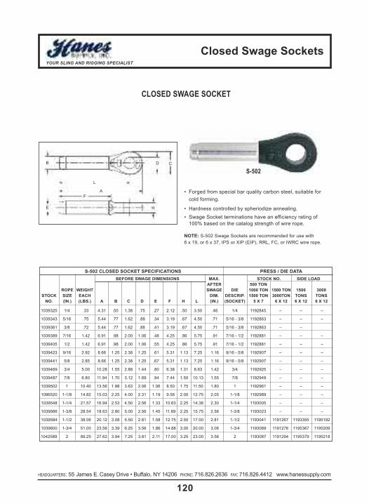
closed swage socketsYOUR SLING AND RIGGING SPECIALIST
120HEADQUARTERS: 55 James E. Casey Drive • Buffalo, NY 14206 PHONE: 716.826.2636 FAX: 716.826.4412 www.hanessupply.com HEADQUARTERS: 55 James E. Casey Drive • Buffalo, NY 14206 PHONE: 716.826.2636 FAX: 716.826.4412 www.hanessupply.com
CLOSED SWAGE SOCKET
• Forged from special bar quality carbon steel, suitable forcold forming.
• Hardness controlled by spheriodize annealing.• Swage Socket terminations have an efficiency rating of
100% based on the catalog strength of wire rope.
note: S-502 Swage Sockets are recommended for use with 6 x 19, or 6 x 37, IPS or XIP (EIP), RRL, FC, or IWRC wire rope.
s-502 closeD socket sPecIfIcatIons PRess / DIe DatabefoRe sWaGe DIMensIons MaX. stock no. sIDe loaD
afteR 500 tonRoPe WeIGHt sWaGe DIe 1000 ton 1500 ton 1500 3000
stock sIze eacH DIM. DescRIP. 1500 ton 3000ton tons tonsno. (In.) (lbs.) a b c D e f H l (In.) (socket) 5 X 7 6 X 12 6 X 12 6 X 12
1039325 1/4 .33 4.31 .50 1.38 .75 .27 2.12 .50 3.50 .46 1/4 1192845 – – –
1039343 5/16 .75 5.44 .77 1.62 .88 .34 3.19 .67 4.50 .71 5/16 - 3/8 1192863 – – –
1039361 3/8 .72 5.44 .77 1.62 .88 .41 3.19 .67 4.50 .71 5/16 - 3/8 1192863 – –
1039389 7/16 1.42 6.91 .98 2.00 1.06 .48 4.25 .86 5.75 .91 7/16 - 1/2 1192881 – – –
1039405 1/2 1.42 6.91 .98 2.00 1.06 .55 4.25 .86 5.75 .91 7/16 - 1/2 1192881 – – –
1039423 9/16 2.92 8.66 1.25 2.38 1.25 .61 5.31 1.13 7.25 1.16 9/16 - 5/8 1192907 – – –
1039441 5/8 2.85 8.66 1.25 2.38 1.25 .67 5.31 1.13 7.25 1.16 9/16 - 5/8 1192907 – – –
1039469 3/4 5.00 10.28 1.55 2.88 1.44 .80 6.38 1.31 8.63 1.42 3/4 1192925 – – –
1039487 7/8 6.80 11.94 1.70 3.12 1.69 .94 7.44 1.50 10.13 1.55 7/8 1192949 – – –
1039502 1 10.40 13.56 1.98 3.63 2.06 1.06 8.50 1.75 11.50 1.80 1 1192961 – – –
1096520 1-1/8 14.82 15.03 2.25 4.00 2.31 1.19 9.56 2.00 12.75 2.05 1-1/8 1192989 – – –
1039548 1-1/4 21.57 16.94 2.53 4.50 2.56 1.33 10.63 2.25 14.38 2.30 1-1/4 1193005 – – –
1039566 1-3/8 28.54 18.63 2.80 5.00 2.56 1.45 11.69 2.25 15.75 2.56 1-3/8 1193023 – – –
1039584 1-1/2 38.06 20.12 3.08 5.50 2.81 1.58 12.75 2.50 17.00 2.81 1-1/2 1193041 1191267 1193355 1195192
1039600 1-3/4 51.00 23.56 3.39 6.25 3.56 1.86 14.88 3.00 20.00 3.06 1-3/4 1193069 1191276 1195367 1195209
1042589 2 89.25 27.62 3.94 7.25 3.81 2.11 17.00 3.25 23.00 3.56 2 1193087 1191294 1195379 1195218
S-502
HE
FA
L
CDB

swage buttons/socket compoundYOUR SLING AND RIGGING SPECIALIST
121HEADQUARTERS: 55 James E. Casey Drive • Buffalo, NY 14206 PHONE: 716.826.2636 FAX: 716.826.4412 www.hanessupply.com
DIMensIons (In)RoPeIteM DIaMeteR a b c D e
1 SB 1/8 27/64 1/2 .141 3/8 39/642 SB 5/32 1/2 39/64 .172 7/16 23/323 SB 3/16 9/16 45/64 .203 1/2 27/324 SB 7/32 41/64 13/16 .234 9/16 31/325 SB 1/4 41/64 1-1/16 .296 9/16 1-13/646 SB 9/32 49/64 1-1/32 .313 11/16 1-13/647 SB 5/16 27/32 1-1/8 .358 3/4 1-21/648 SB 3/8 27/32 1-31/64 .421 3/4 1-11/169 SB 7/16 1-1/8 1-5/8 .484 1 1-15/16
10 SB 1/2 1-17/64 1-57/64 .547 1-1/8 2-11/6411 SB 9/16 1-13/32 2-1/64 .609 1-1/4 2-13/3212 SB 5/8 1-35/64 2-27/64 .672 1-3/8 2-57/6413 SB 3/4 1-11/16 2-47/64 .796 1-1/2 3-1/414 SB 7/8 1-31/32 3-17/64 .936 1-3/4 3-55/6415 SB 1 2-1/4 3-43/64 1.061 2 4-23/6416 SB 1-1/8 2-17/32 4-3/64 1.188 2-1/4 4-23/6417 SB 1-1/4 2-13/16 4-37/64 1.328 2-1/2 5-27/6418 SB 1-3/8 3-3/32 5-5/64 1.453 2-3/4 6-1/3219 SB 1-1/2 3-3/8 5-15/32 1.578 3 6-33/64
S-409 SWAGE BUTTONS
• Low carbon steel• Spherodize annealed• Quality controlled• Economical to use
A multi-purpose fitting for many swagingapplications. Manufactured from a specialanalysis high quality, low carbon steel, andlater heat treated. They are precisionmade with constant quality control checksthroughout all stages of manufacturing toassure the best in quality and perform-ance.
NOTE: Length is measured from outside end of terminal.
E
D
C
B
AbefoRe sWaGe
AFTER SWAGE
aMoUnt of WIRelock® ReQUIReDWIRe WIReRoPe WIRelock® RoPe WIRelock®
sIze ReQUIReD sIze ReQUIReD(In.) (cc) (In.) (cc)1/4 9 1-3/4 700
5/16 17 1-7/8 7003/8 17 2 1265
7/16 35 2-1/8 12651/2 35 2-1/4 1410
9/16 52 2-3/8 14105/8 52 2-1/2 18303/4 86 2-5/8 18307/8 125 2-3/4 22501 160 3 3160
1-1/8 210 3-1/4 37951-1/4 350 3-1/2 49201-3/8 350 3-3/4 59801-1/2 420 4 77301-5/8 495
WIRELOCK® - RESIN FOR SPELTER SOCKETS
• Ideal for on-site applications• Improved fatigue life• For use on 416 & 417 Spelter
Sockets only• 100% termination efficiency• Temperature operating range
from -65°F to +240°F• One Booster pack needed if
pouring temperature is 35°F to 48°F• Two Booster packs needed if
pouring temperature is 27°F to 35°F
W416-7 kIts boosteRkIt kIts stock Wt. eacH Pack
sIze PeR case no. (lbs.) stock no.100 CC 20 1039602 .62 1039603250 CC 12 1039604 1.25 1039605500 CC 12 1039606 2.54 10396071000 CC 12 1039608 4.59 10396092000 CC 12 1039610 9.00 1039611
aPPRoXIMate U.s. MeasUReMents250cc Kit 1 Cup500cc Kit 1 Pint1,000cc Kit 1 Quart
nato nUMbeRs100cc 8030-21-902-1823250cc 8030-21-902-1824500cc 8030-21-902-18251,000cc 8030-21-902-1826
Witnessed and tested by American Bureau of Shipping (ABS)
W416-7

swaged socketsYOUR SLING AND RIGGING SPECIALIST
122HEADQUARTERS: 55 James E. Casey Drive • Buffalo, NY 14206 PHONE: 716.826.2636 FAX: 716.826.4412 www.hanessupply.com HEADQUARTERS: 55 James E. Casey Drive • Buffalo, NY 14206 PHONE: 716.826.2636 FAX: 716.826.4412 www.hanessupply.com
SWAGED SOCKETS ASSEMBLIES
caPacItY (tons*)6X19 & 6X37
IWRcRoPe
DIa. lPs XIP
1/4 .588 .695/16 .916 1.053/8 1.3 1.5
7/16 1.778 2.041/2 2.3 2.66
9/16 2.9 3.365/8 3.58 4.123/4 5.12 5.887/8 6.92 7.961 8.98 10.34
1-1/8 11.3 13.1-1/4 13.88 15.981-3/8 16.7 19.21-1/2 19.78 22.81-3/4 26.6 30.6
2 34.4 39.62-1/4 43. 49.42-1/2 52.4 60.4
In mechanically swaged fittings, high pres-sure presses and precision dies causemetal of the socket to flow around wiresand strands to offer the ultimate in com-pactness and strength with minimumweight. Material is weldless, drop-forgedsteel.
Normally, only regular lay rope is used.Swaged assemblies are interchangeablewith *poured sockets up through 2" rope diameters. Assembly length is measuredfrom centerline of pins for both open andclosed sockets.When purchasing, indicate choice of end fittings by the suffixes “OS” or “CS” after the stock number, for open or closed typefittings. Pins and cotters are supplied asstandard on open fittings, but assembliesmay be specified without pins. Fittings are assembled in the same plane unlessspecified otherwise when ordered.
* These sockets are not interchangeable with zinc poured sockets.
oPen socket DIaMeteR (In) closeD socket DIaMeteR (In)
RoPe ls lsDIa. c D e f PIn as (aPPRoX.) c D e as (aPPRoX.)
1/4 11/16 5/16 1-1/2 1-3/8 .688 .438 4-7/16 1-7/16 .750 1/2 .438 3-15/165/16 13/16 13/32 1-3/4 1-5/8 .812 .688 5-15/16 1-11/16 .875 11/16 .688 5-1/83/8 13/16 13/32 1-3/4 1-5/8 .812 .688 5-15/16 1-11/16 .875 11/16 .688 5-1/8
7/16 1 1/2 2 2 1.00 .875 7-5/8 2 1.063 7/8 .875 6-5/81/2 1 1/2 2 2 1.00 .875 7-5/8 2 1.063 7/8 .875 6-5/89/16 1-1/4 5/8 2-1/4 2-1/2 1.19 1.125 9-3/16 2-1/2 1.250 1-1/8 1.125 8-5/16
5/8 1-1/4 5/8 2-1/4 2-1/2 1.19 1.125 9-3/16 2-1/2 1.250 1-1/8 1.125 8-5/163/4 1-1/2 3/4 2-3/4 3 1.38 1.375 11-1/4 3 1.438 1-5/16 1.375 9-15/167/8 1-3/4 15/16 3-1/4 3-3/8 1.63 1.50 13-1/8 3-1/2 1.688 1-1/2 1.50 11-5/8
1 2 1-1/32 3-3/4 4 2.00 1.75 15-1/16 4 2.063 1-3/4 1.75 13-3/161-1/8 2-1/4 1-3/16 4-1/4 4-1/2 2.25 2.00 16-15/16 4-1/2 2.313 2 2.00 14-11/161-1/4 2-1/2 1-3/16 4-3/4 5 2.50 2.25 18-5/8 5 2.563 2-1/4 2.25 16-1/2
1-3/8 2-1/2 1-5/16 5-1/4 5-1/4 2.50 2.50 20-1/2 5-1/4 2.563 2-1/4 2.50 18-1/81-1/2 3 1-7/16 5-3/4 5-3/4 2.75 2.75 22-5/16 5-1/2 2.813 2-1/2 2.75 19-9/161-3/4 3-1/2 1-11/16 6-3/4 7 3.50 3.00 26 6-3/4 3.563 3 3.00 23
2 4 1-13/16 8 8 3.75 3.50 30-1/8 7-3/4 3.813 3-1/4 3.50 26-7/162-1/4* 4-1/4 2-1/8 6-3/4 8-3/4 4.25 4.00 31-1/4 8-3/4 4.312 4 4.00 28-1/22-1/2* 4-1/4 2-1/8 6-3/4 8-3/4 4.25 4.40 33-3/8 8-3/4 4.312 4 4.40 30-1/4
Pins atRight Angles
500-R
Pins atRight Angles
502-R
Pins atRight Angles
503-R
PinsParallel500-P
PinsParallel502-P
PinsParallel503-P
os-os
cs-cs
os-cs
lenGtH

eye boltsYOUR SLING AND RIGGING SPECIALIST
123HEADQUARTERS: 55 James E. Casey Drive • Buffalo, NY 14206 PHONE: 716.826.2636 FAX: 716.826.4412 www.hanessupply.com
WARNING!
Important Safety Information – Read and Follow
Inspection/Maintenance safety
• Always inspect eye bolt before use.
• Never use eye bolt that shows signs of wear or damage.
• Never use eye bolt if eye or shank is bent or elongated.
• Always be sure threads on shank and receiving holesare clean.
• Never machine, grind, or cut eye bolt.
assembly safety
• Never exceed load limits specified in Table I.
• Never use regular nut eye bolts for angular lifts.
• Always use shoulder nut eye bolts (or machinery eye bolts) for angular lifts.
• For angular lifts, adjust working load as follows:
• Never undercut eye bolt to seat shoulder against the load.
• Always countersink receiving hole or use washers to seat shoulder.
• Always screw eye bolt down completely for proper seating.
• Always tighten nuts securely against the load.
• Use only if trained.• loads may slip or fall if proper eye bolt
assembly & lifting procedures are not used.• a falling load can seriously injure or kill.• Read, understand & follow all eye bolt safety
information & diagrams presented here.
foRGeD eYe boltWaRnInGs anD aPPlIcatIon
InstRUctIons
Regular Nut Eye BoltG-291
Shoulder Nut Eye BoltG-277
Machinery Eye Bolt
S-279 /M-279
DIRectIon of PUll aDJUsteD WoRkInG loaD45 degrees 30% of rated working load90 degrees 25% of rated working load
table I (In-lIne loaD)size (in.) Working load limit (lbs.)
1/4 6505/16 12003/8 15501/2 26005/8 52003/4 72007/8 106001 13300
1-1/4 210001-1/2 24000
• Thickness of spacersmust exceed this distance between thebottom of the load andthe last thread of theeye bolt.
• Place washers or spacers between nutand load so that whenthe nut is tightened securely, the shoulder is secured flush againstthe load surface.
• The threaded shankmust protrudethrough the loadsufficiently to allowfull engagement ofthe nut.
• If the eye bolt protrudes so farthrough the loadthat the nut cannotbe tightened se-curely against theload, use properlysized washers totake up the excessspace BETWEENTHE NUT AND THE LOAD.
Shoulder Nut Eye Bolt –Installation for Angular Loading

eye boltsYOUR SLING AND RIGGING SPECIALIST
124HEADQUARTERS: 55 James E. Casey Drive • Buffalo, NY 14206 PHONE: 716.826.2636 FAX: 716.826.4412 www.hanessupply.com HEADQUARTERS: 55 James E. Casey Drive • Buffalo, NY 14206 PHONE: 716.826.2636 FAX: 716.826.4412 www.hanessupply.com
RightMore thanone eye boltdia. ofthreads,only (1) nutrequired.
Do not reeve slingsfrom one eye bolt to an-other. This will alter theload & angle of loadingon the eye bolt.
After slings have been prop-erly attached to the eyebolts, apply force slowly.Watch the load carefully& be prepared to stopapplying force ifthe load startsbuckling.
Buckling may occur ifthe load is not stiff
enough to resist thecompressive forces
which result fromthe angular load-ing.
Resultant Load
Wrong
Tighten hex nut securelyagainst load
One eyebolt dia. ofthreads orless, usetwo (2)nuts.
Tighten hex nut securelyagainst load
TightenHex NutSecurelyAgainstLoad
One eye bolt dia. or less
2x Dia.(Min.)
Tap Depth:2.5 x Dia.
Right Right Wrong
IMPoRtant – ReaD anD UnDeRstanD tHese InstRUctIons befoRe UsInG eYe bolts.
Regular Nut & Shoulder Nut Eye Bolt – Installation for In-Line Loading
Operating Safety• Always inspect eye bolt before use.• Always lift load with a steady, even pull – do not jerk.• Always apply load to eye bolt in the plane of the eye,
not at an angle.
• Never exceed the capacity of the eyebolt – See Table I.• When using lifting slings of two or more legs, make sure
the loads in the legs are calculated using the angle fromthe vertical to the leg and properly size the shoulder nutor machinery eye bolt for the angular load.
Machinery Eye Bolt – Installation for In-Line & Angular LoadingThese eye bolts are primarily intended to be installed intotapped holes.
1. After the loads on the eye bolts have been calculated,select the proper size eye bolt for the job.For angular lifts, adjust working load as follows:
2. Drill and tap the load to the correct sizes to a minimumdepth of one-half the eye bolt size beyond the shanklength of the machinery eye bolt.
3. Thread the eye bolt into the load until the shoulder isflush and securely tightened against the load.
4. If the plane of the machinery eye bolt is not aligned withthe sling line, estimate the amount of unthreading rota-tion necessary to align the plane of the eye properly.
5. Remove the machinery eye bolt from the load and addshims (washers) of proper thickness to adjust the angleof the plane of the eye to match the sling line. Use TableII to estimate the required shim thickness for the amountof unthreading rotation required.
DIRectIon of PUll aDJUsteD WoRkInG loaD45 degrees 30% of rated working load90 degrees 25% of rated working load
Shim added to change eye alignment 90°
Min. tap depth isbasic shank lengthplus one-half thenominal eye boltdiameter.
table IIsHIM tHIckness ReQUIReD
eYe bolt sIze to cHanGe RotatIon 90°(In.) (In.)1/4 .0125
5/16 .01393/8 .01561/2 .01925/8 .02273/4 .02507/8 .02781 .0312
1-1/4 .03571-1/2 .0417

eye boltsYOUR SLING AND RIGGING SPECIALIST
125HEADQUARTERS: 55 James E. Casey Drive • Buffalo, NY 14206 PHONE: 716.826.2636 FAX: 716.826.4412 www.hanessupply.com
REGULAR NUT EYE BOLTS
• Recommended for straight line pull.• All Bolts Hot Dip galvanized after threading.• Furnished with standard Hot Dip galvanized hex nuts.• Forged Steel – Quenched and Tempered.• Crosby products meet or exceed all the requirements of ASMEB30.26 including identification, ductility, design factor, proof loadand temperature requirements. Importantly, Crosby products meetother critical performance requirements inluding fatigue life, impactproperties & material traceability, not addressed by ASME B30.26.
G-291
sHank WoRkInG WeIGHtDIaMeteR G-291 loaD PeR DIMensIons (In)& lenGtH stock no. lIMIt* 100
(In.) GalV. (lbs.) (lbs.) a b c D e f G H1/4 x 2 1043230 650 8.20 .25 .50 1.00 .25 1.50 2.00 3.06 .561/4 x 4 1043258 650 11.70 .25 .50 1.00 .25 2.50 4.00 5.06 .56
5/16 x 2-1/4 1043276 1200 13.30 .31 .62 1.25 .31 1.50 2.25 3.56 .695/16 x 4-1/4 1043294 1200 25.00 .31 .62 1.25 .31 2.50 4.25 5.56 .693/8 x 2-1/2 1043310 1550 23.30 .38 .75 1.50 .38 1.50 2.50 4.12 .883/8 x 4-1/2 1043338 1550 29.50 .38 .75 1.50 .38 2.50 4.50 6.12 .88
3/8 x 6 1043356 1550 35.20 .38 .75 1.50 .38 2.50 6.00 7.62 .881/2 x 3-1/4 1043374 2600 50.30 .50 1.00 2.00 .50 1.50 3.25 5.38 1.12
1/2 x 6 1043392 2600 66.10 .50 1.00 2.00 .50 3.00 6.00 8.12 1.121/2 x 8 1043418 2600 82.00 .50 1.00 2.00 .50 3.00 8.00 10.12 1.121/2 x 10 1043436 2600 88.00 .50 1.00 2.00 .50 3.00 10.00 12.12 1.121/2 x 12 1043454 2600 114.20 .50 1.00 2.00 .50 3.00 12.00 14.12 1.125/8 x 4 1043472 5200 103.10 .62 1.25 2.50 .62 2.00 4.00 6.69 1.445/8 x 6 1043490 5200 118.20 .62 1.25 2.50 .62 3.00 6.00 8.69 1.445/8 x 8 1043515 5200 135.10 .62 1.25 2.50 .62 3.00 8.00 10.69 1.445/8 x 10 1043533 5200 153.60 .62 1.25 2.50 .62 3.00 10.00 12.69 1.445/8 x 12 1043551 5200 167.10 .62 1.25 2.50 .62 4.00 12.00 14.69 1.44
3/4 x 4-1/2 1043579 7200 168.60 .75 1.50 3.00 .75 2.00 4.50 7.69 1.693/4 x 6 1043597 7200 184.50 .75 1.50 3.00 .75 3.00 6.00 9.19 1.693/4 x 8 1043613 7200 207.90 .75 1.50 3.00 .75 3.00 8.00 11.19 1.693/4 x 10 1043631 7200 235.00 .75 1.50 3.00 .75 3.00 10.00 13.19 1.693/4 x 12 1043659 7200 257.50 .75 1.50 3.00 .75 4.00 12.00 15.19 1.693/4 x 15 1043677 7200 298.00 .75 1.50 3.00 .75 5.00 15.00 18.19 1.697/8 x 5 1043695 10600 270.00 .88 1.75 3.50 .88 2.50 5.00 8.75 2.007/8 x 8 1043711 10600 308.00 .88 1.75 3.50 .88 4.00 8.00 11.75 2.007/8 x 12 1043739 10600 400.00 .88 1.75 3.50 .88 4.00 12.00 15.75 2.00
1 x 6 1043757 13300 421.00 1.00 2.00 4.00 1.00 3.00 6.00 10.31 2.311 x 9 1043775 13300 468.50 1.00 2.00 4.00 1.00 4.00 9.00 13.31 2.311 x 12 1043793 13300 540.00 1.00 2.00 4.00 1.00 4.00 12.00 16.31 2.311 x 18 1043819 13300 650.00 1.00 2.00 4.00 1.00 7.00 18.00 22.31 2.31
1-1/4 x 8 1043837 21000 750.00 1.25 2.50 5.00 1.25 4.00 8.00 13.38 2.881-1/4 x 12 1043855 21000 900.00 1.25 2.50 5.00 1.25 4.00 12.00 17.38 2.881-1/4 x 20 1043873 21000 1210.00 1.25 2.50 5.00 1.25 6.00 20.00 25.38 2.88
* Ultimate Load is 5 times Working Load Limit.
A
E
G
F H D
B C
! see aPPlIcatIon anDWaRnInG InfoRMatIon

eye boltsYOUR SLING AND RIGGING SPECIALIST
126HEADQUARTERS: 55 James E. Casey Drive • Buffalo, NY 14206 PHONE: 716.826.2636 FAX: 716.826.4412 www.hanessupply.com HEADQUARTERS: 55 James E. Casey Drive • Buffalo, NY 14206 PHONE: 716.826.2636 FAX: 716.826.4412 www.hanessupply.com
sHank WoRkInGDIaMeteR G-277 loaD WeIGHt DIMensIons (In)& lenGtH stock no. lIMIt* PeR 100
(In.) GalV. (lbs.) (lbs.) a b c D e f G H J1/4 x 2 1045014 650 6.60 .25 .50 .88 .19 1.50 2.00 2.94 .50 .471/4 x 4 1045032 650 9.10 .25 .50 .88 .19 2.50 4.00 4.94 .50 .47
5/16 x 2-1/4 1045050 1200 12.50 .31 .62 1.12 .25 1.50 2.25 3.50 .69 .565/16 x 4-1/4 1045078 1200 18.80 .31 .62 1.12 .25 2.50 4.25 5.50 .69 .563/8 x 2-1/2 1045096 1550 21.40 .38 .75 1.38 .31 1.50 2.50 3.97 .78 .663/8 x 4-1/2 1045112 1550 25.30 .38 .75 1.38 .31 2.50 4.50 5.97 .78 .661/2 x 3-1/4 1045130 2600 42.60 .50 1.00 1.75 .38 1.50 3.25 5.12 1.00 .91
1/2 x 6 1045158 2600 56.60 .50 1.00 1.75 .38 3.00 6.00 7.88 1.00 .915/8 x 4 1045176 5200 68.60 .62 1.25 2.25 .50 2.00 4.00 6.44 1.31 1.125/8 x 6 1045194 5200 102.40 .62 1.25 2.25 .50 3.00 6.00 8.44 1.31 1.12
3/4 x 4-1/2 1045210 7200 144.50 .75 1.50 2.75 .62 2.00 4.50 7.44 1.56 1.383/4 x 6 1045238 7200 167.50 .75 1.50 2.75 .62 3.00 6.00 8.94 1.56 1.387/8 x 5 1045256 10600 225.00 .88 1.75 3.25 .75 2.50 5.00 8.47 1.84 1.561 x 6 1045292 13300 366.60 1.00 2.00 3.75 .88 3.00 6.00 9.97 2.09 1.811 x 9 1045318 13300 422.50 1.00 2.00 3.75 .88 4.00 9.00 12.97 2.09 1.81
1-1/4 x 8 1045336 21000 650.00 1.25 2.50 4.50 1.00 4.00 8.00 12.72 2.47 2.281-1/4 x 12 1045354 21000 795.00 1.25 2.50 4.50 1.00 4.00 12.00 16.72 2.47 2.281-1/2 x 15 1045372 24000 1425.00 1.50 3.00 5.50 1.25 6.00 15.00 20.75 3.00 2.75
SHOULDER NUT EYE BOLTS
• Forged Steel• Hot Dip galvanized• Furnished with standard Hot Dip galvanized, heavy hex nuts
G-277
sHank WoRkInGDIaMeteR G-275 loaD WeIGHt DIMensIons (In)& lenGtH stock no. lIMIt* PeR 100
(In.) GalV. (lbs.) (lbs.) a b c D e f G H J
1/4 x 2 1046111 500 4.30 .25 1.50 2.00 2.50 2.94 .50 .88 .19 .475/16 x 2-1/4 1046139 800 12.50 .31 1.69 2.25 2.94 3.50 .63 1.13 .25 .563/8 x 2-1/2 1046157 1200 19.00 .38 1.88 2.50 3.28 3.97 .75 1.38 .31 .661/2 x 3-1/4 1046175 2200 37.50 .50 2.44 3.25 4.25 5.12 1.00 1.75 .38 .91
5/8 x 4 1046193 3500 75.00 .62 3.00 4.00 5.31 6.44 1.25 2.25 .50 1.12
*Ultimate Load is 5 times Working Load Limit.
• Forged Steel – Quenched and Tempered• Hot Dip galvanized
SCREW EYE BOLTSG-275
A
E
G
F HD
B C
J
A
E
GF
H
D
BC
J
! see aPPlIcatIon anDWaRnInG InfoRMatIon

eye boltsYOUR SLING AND RIGGING SPECIALIST
127HEADQUARTERS: 55 James E. Casey Drive • Buffalo, NY 14206 PHONE: 716.826.2636 FAX: 716.826.4412 www.hanessupply.com
SHOULDER TYPE MACHINE EYE BOLTS
• Forged • 1030 Carbon Steel• Self-Colored
tHReaD centeR aPPRoX.sIze sHank I.D. o.D. oVeRall of eYe to Wt. PeR RateD
stock Unc-2a lenGtH eYe eYe lenGtH sHoUlDeR 100 Pcs. caP.no. a b c D e f blanks* (lbs.) (lbs.)
14611 1/4 - 20 1 3/4 1-3/16 2-3/8 3/4 R14611 5.0 500
14621 5/16 - 18 1-1/8 7/8 1-7/16 2-13/16 15/16 R14621 9.6 900
14631 3/8 - 16 1-1/4 1 1-11/16 3-1/4 1-1/8 R14631 16.0 1,300
14638 7/16 - 14 1-3/8 1-3/32 1-13/16 3-9/16 1-1/4 R14638 24.2 1,800
14641 1/2 - 13 1-1/2 1-3/16 2-1/8 3-31/32 1-3/8 R14641 34.8 2,400
14650 9/16 - 12 1-3/4 1-3/8 2-9/16 4-3/4 1-21/32 R14650 47.0 3,200
14661 5/8 - 11 1-3/4 1-3/8 2-9/16 4-3/4 1-21/32 R14661 67.0 4,000
14672 3/4 - 10 2 1-1/2 2-13/16 5-1/4 1-13/16 R14682 100.0 5,000
14682 7/8 - 9 2-1/4 1-11/16 3-3/16 6 2-1/8 R14682 163.0 7,000
14702 1 - 8 2-1/2 1-13/16 3-9/16 6-5/8 2-5/16 R14702 222.0 9,000
14712 1-1/8 - 7 2-3/4 2 4-1/16 7-17/32 2-11/16 R14712 340.0 12,000
14723 1-1/4 - 7 3 2-13/16 4-7/16 8-7/32 2-15/16 R14723 444.0 15,000
14753 1-1/2 - 6 3-1/2 2-1/2 5-3/16 9-15/32 3-5/16 R14753 736.0 21,000
14770 1-3/4 - 5 3-3/4 2-7/8 6 10-13/16 4 R14770 1135.0 28,000
14780 2 - 4-1/2 4 3-1/4 6-7/8 11-7/8 4-3/8 R14780 1670.0 38,000
*Blanks have no rated capacity.
! see aPPlIcatIon anDWaRnInG InfoRMatIon

Hoist RingsYOUR SLING AND RIGGING SPECIALIST
128HEADQUARTERS: 55 James E. Casey Drive • Buffalo, NY 14206 PHONE: 716.826.2636 FAX: 716.826.4412 www.hanessupply.com HEADQUARTERS: 55 James E. Casey Drive • Buffalo, NY 14206 PHONE: 716.826.2636 FAX: 716.826.4412 www.hanessupply.com
RateD tHReaD stanDaRD U-baR lonG U-baRloaDs sIze PaRt PaRt toRQUe Wt.(lbs.) (In.) a c D e no. b f no. b f G H (ft/lb) (lbs)
600 1/4 - 20 0.43 0.71 3/8 0.54 46100 1.27 2.67 – – – 1.84 1.00 6 0.3800 5/16 - 18 0.43 0.71 3/8 0.29 46102 1.27 2.67 – – – 1.84 1.00 7 0.3800 5/16 - 18 0.43 0.71 3/8 0.54 46104 1.27 2.67 – – – 1.84 1.00 7 0.3
1,000 3/8 - 16 0.43 1.71 3/8 0.54 46106 1.27 2.67 – – – 1.84 1.00 12 0.32,000 7/16 - 14 0.70 0.93 1/2 1.07 46606 1.84 3.77 – – – 2.58 1.49 22 1.02,500 1/2 - 13 0.70 0.93 1/2 1.07 46602 1.84 3.77 – – – 2.58 1.49 28 1.02,000 7/16 - 14 0.88 1.22 3/4 0.78 46000 2.31 4.78 46638 4.25 6.72 3.52 1.99 22 2.62,500 1/2 - 13 0.88 1.22 3/4 0.78 46008 2.31 4.78 46644 4.25 6.72 3.52 1.99 28 2.62,500 1/2 - 13 0.88 1.22 3/4 1.03 46010 2.31 4.78 46646 4.25 6.72 3.52 1.99 28 2.62,500 1/2 - 13 0.88 1.22 3/4 1.28 46012 2.31 4.78 46648 4.25 6.72 3.52 1.99 28 2.64,000 5/8 - 11 0.88 1.22 3/4 0.78 46002 2.18 4.78 – – – 3.52 1.99 60 2.64,000 5/8 - 11 0.88 1.22 3/4 1.03 46004 2.18 4.78 46640 4.12 6.72 3.52 1.99 60 2.64,000 5/8 - 11 0.88 1.22 3/4 1.28 46006 2.18 4.78 46642 4.12 6.72 3.52 1.99 60 2.65,000 3/4 - 10 0.88 1.22 3/4 1.03 46014 2.06 4.78 46650 4.00 6.72 3.52 1.99 100 3.05,000 3/4 - 10 0.88 1.22 3/4 1.53 46018 2.06 4.78 46654 4.00 6.72 3.52 1.99 100 3.07,000 3/4 - 10 1.40 1.71 1 1.04 46204 3.06 6.52 46658 4.65 8.11 5.14 3.00 100 7.07,000 3/4 - 10 1.40 1.71 1 2.54 46206 3.06 6.52 46660 4.65 8.11 5.14 3.00 100 7.08,000 7/8 - 9 1.40 1.71 1 1.04 46202 2.93 6.52 46656 4.52 8.11 5.14 3.00 160 7.08,000 7/8 - 9 1.40 1.71 1 1.29 46203 2.93 6.52 46652 4.52 8.11 5.14 3.00 160 7.010,000 1 - 8 1.40 1.71 1 1.29 46210 2.81 6.52 46662 4.40 8.11 5.14 3.00 230 7.510,000 1 - 8 1.40 1.71 1 1.54 46212 2.81 6.52 46664 4.40 8.11 5.14 3.00 230 7.510,000 1 - 8 1.40 1.71 1 2.29 46214 2.81 6.52 46666 4.40 8.11 5.14 3.00 230 7.515,000 1-1/4 - 7 1.75 2.11 1-1/4 1.89 46802 4.12 8.73 – – – 6.50 3.76 470 14.020,000 1-3/8 - 6 2.00 2.36 1-1/2 2.64 46702 5.20 10.59 – – – 7.46 4.31 540 22.024,000 1-1/2 - 6 2.25 2.81 1-3/4 2.70 46404 6.41 12.47 – – – 8.55 4.87 800 34.024,000 1-3/4 - 5 2.25 2.81 1-3/4 2.70 46408 6.41 12.47 – – – 8.55 4.87 800 34.030,000 2 - 4-1/2 2.25 2.81 1-3/4 2.96 46400 5.91 12.47 – – – 8.55 4.87 800 36.050,000 2-1/2 - 8 3.00 4.09 2-1/4 4.00 47002 8.03 16.87 – – – 11.67 6.52 2100 88.050,000 2-1/2 - 4 3.00 4.09 2-1/4 4.00 47006 8.03 16.87 – – – 11.67 6.52 2100 88.075,000 3 - 4 3.75 5.27 2-3/4 4.20 47200 8.48 19.50 – – – 14.15 8.10 4300 166.0100,000 3-1/2 - 4 4.00 6.06 3-1/4 7.00 47402 9.28 22.09 – – – 15.90 8.60 5100 265.0250,000 6 - 4 6.00 14.00 5 9.00 47602 14.00 33.00 – – – 25.00 13.00 9900 790.0
ACTEK™ SWIVEL (SAFETY) HOIST RINGS
• Rated load from 400 lbs. to 125 tons.• Pivots 180°/Swivels 360°• Material: AISI 4140 aircraft quality• Finish: Black oxide per mil spec cadmium plated
• Safety factor: 5:1• 100% magnetic particle inspected• Certified heat treatment
UNC THREADS MetRIc tHReaDsSee following page
UNC THREADS

Hoist RingsYOUR SLING AND RIGGING SPECIALIST
129HEADQUARTERS: 55 James E. Casey Drive • Buffalo, NY 14206 PHONE: 716.826.2636 FAX: 716.826.4412 www.hanessupply.com
RateD stanDaRD U-baR lonG U-baRloaDs tHReaD PaRt PaRt toRQUe Wt.(kGs.) sIze a c D e no. b f no. b f G H (kGM.) (kGs.)
400 M8 x 1.25 11 18 10 13 46912 32 68 – – – 47 25 0.86 0.17500 M10 x 1.50 11 18 10 18 46916 30 68 – – – 47 25 1.5 0.17
1,050 M12 x 1.75 22 30 19 19 46924 60 121 47124 110 171 89 51 3.7 1.081,900 M16 x 2.00 22 30 19 29 46930 56 121 47130 106 171 89 51 8.4 1.122,150 M20 x 2.50 22 30 19 34 46936 52 121 47136 102 171 89 51 14 1.193,000 M20 x 2.50 36 43 25 32 46942 78 166 47142 118 206 131 76 14 3.034,200 M24 x 3.00 36 43 25 37 46948 74 166 47148 114 206 131 76 14 3.104,200 M30 x 3.50 36 43 25 58 – – – 46950 108 206 131 76 60 3.107,000 M30 x 3.50 45 54 32 42 46956 106 222 – – – 165 95 60 6.307,000 M30 x 3.50 45 54 32 62 46958 106 222 – – – 165 95 60 6.4011,000 M36 x 4.00 57 71 44 64 46966 166 317 – – – 217 124 100 15.5012,500 M42 x 4.50 57 71 44 82 46968 160 317 – – – 217 124 100 16.0013,500 M48 x 5.00 57 71 44 82 46970 154 317 – – – 217 124 100 16.8022,300 M64 x 6.00 76 103 57 101 46972 204 428 – – – 296 165 273 39.0031,500 M72 x 6.00 95 133 70 132 46988 220 495 – – – 359 206 559 74.0051,000 M90 x 6.00 102 153 83 177 46990 235 561 – – – 404 218 663 118.00
ACTEK™ SWIVEL (SAFETY) HOIST RINGS
• Rated load from 400 lbs. to 125 tons.• Pivots 180°/Swivels 360°• Material: AISI 4140 aircraft quality• Finish: Black oxide per mil spec cadmium plated
• Safety factor: 5:1• 100% magnetic particle inspected• Certified heat treatment
MetRIc tHReaDs Unc tHReaDsSee previous page
METRIC THREADS

lifting clampsYOUR SLING AND RIGGING SPECIALIST
130HEADQUARTERS: 55 James E. Casey Drive • Buffalo, NY 14206 PHONE: 716.826.2636 FAX: 716.826.4412 www.hanessupply.com HEADQUARTERS: 55 James E. Casey Drive • Buffalo, NY 14206 PHONE: 716.826.2636 FAX: 716.826.4412 www.hanessupply.com
“GXL” CLAMPS• Available in a 1/2, 1 and 2 ton capacity.• Exclusive feature is a patented wear indicator system. When any of cam’s straight line, convex teeth are flattened between unique wear indicator grooves, it is time to change the cam.
• Drop forged and heat treated components, with gripping surfaces of case hardened alloy steel.• Newly designed “Cam Engaging Lever” keeps the cam in contact with the plate. The tension arm and spring mechanism facilitate attaching and removing the clamp. These clamps will not lift plate when in the “lever open” position.
Warning: Never tamper with a clamp’s tension arm and spring mechanism during a lift.
SAC (SCREW-ADJUSTED CAM) PLATE CLAMPS• Recommended for turning plates from horizontal to vertical as well as through a 180O arc.• The convex, serrated cam swivels on a ball joint so that the area of cam engagement increases as load increases
• Drop forged body and shackle.• 100% proof tested with certificate of test attached to each clamp.
Note: Screw needs to be handtight only! Do not over tighten.
HORIZONTAL PLATE CLAMP• Dual springs hold cam on the work while the second clamp is placed• 100% proof tested with certificate of test attached to each clamp• Sold in pairs• One man can handle plates with this clamp
Cam positionunder no load.
Cam under load. Theheavier the load, thegreater the bite.
MERRILLMODEL NO
CATNO
UPC NO020418
GRIP RANGE(IN)
CLAMP WT(LBS)
WLL(TONS)
SAC-1 6421000 096396 0 - 1 6-1/4 1SAC-6 6421001 096402 0 - 2 14-1/4 3SAC-6 6421002 096419 0 - 3 40 6
CATNO
UPC NO020418
GRIP RANGE(IN)
CLAMP WT(LBS)
WLL(TONS)
6422012 187049 1/16 - 5/8 5.5 1/26422001 187687 1/16 - 3/4 8 16422002 187032 1/16 -7/8 10.5 2
MERRILLMODELNO
CATNO
UPCNO
020418WLL(TONS)
GRIPRANGE(IN)
WIDTH(IN)
CAMWIDTH(IN)
WTPER PAIR(LBS)
6H 6421701 096686 6 0 - 1-1/2 5 3/4 32

lifting clampsYOUR SLING AND RIGGING SPECIALIST
131HEADQUARTERS: 55 James E. Casey Drive • Buffalo, NY 14206 PHONE: 716.826.2636 FAX: 716.826.4412 www.hanessupply.com
IPHGZ horizontal lift-ing clamps are de-signed for the liftingand transfer in the hor-izontal position of steelplates, including thinplates that sag.
• Clamps have a latchwhich allows the oprator to position theclamp and move away from the loadbefore the lift begins.
• Suitable for working in conjunction withan angle bench, guillotine, round roller,etc.
IPUZ / UNIVERSAL VERTICAL LIFTING CLAMP
IPUZ vertical lifting clamps areused for lifting, turning (180°)and vertical transfer of steelplates & constructions.
• Hinged hoisting eye allows theuser to place and lift the loadfrom virtually any direction.
• All IPUZ clamps have latchesthat lock in both the open andclosed positions.
• IPUZ clamps with workingload limits greater than 12tons have special built-inhook-up devices to assistin the placement of theselarge-sized clamps.
IPHGZ / IPHGUZ HORIZONTAL LIFTING CLAMP
Wll JaW Wt. PeRoRDeR PeR Pce. oPenInG PIece
MoDel no. (tons) (In.) (lbs.)
0,75 - IPUZ 5051 0,75 0 - 5/8 40,75 - IPSUZ 5052 0,75 5/8 - 1-1/4 40,75 - IPWGUNZ 1601 0,75 0 - 3/4 4
1,5 - IPUZ 5053 1,5 0 - 3/4 171,5 - IPSUZ 5054 1,5 3/4 - 1-5/8 171,5 - IPWGUZ 5186 1,5 0 - 1-3/8 17
3 - IPUZ 5055 3,0 0 - 1 353 - IPSUZ 5056 3,0 1 - 2 36
4,5 - IPUZ 5057 4,5 0 - 1 354,5 - IPSUZ 5058 4,5 1 - 2 37
6 - IPUNZ 5139 6,0 0 - 1-1/4 506 - IPSUNZ 5140 6,0 1-1/4 - 2-1/2 519 - IPUNZ 5141 9,0 0 - 1-5/8 639 - IPSUNZ 5142 9,0 1-5/8 - 3-1/8 64
12 - IPUNZ 5078 12,0 0 - 2-1/8 12612 - IPSUNZ 5079 12,0 2-1/8 - 4-1/4 13016 - IPUNZ 5093 16,0 1/4 - 2-1/2 17416 - IPSUNZ 5094 16,0 2-1/2 - 5 203
22,5 - IPUNZ 5098 22,5 1/4 - 3-1/8 28122,5 - IPSUNZ 5099 22,5 3-1/8 - 6-1/8 288
30 - IPUNZ 5112 30,0 1/4 - 3-1/8 33730 - IPSUNZ 5113 30,0 3-1/8 - 6-1/8 364
Wll JaW Wt. PeRoRDeR PeR Pce. oPenInG PIece
MoDel no. (tons) (In.) (lbs.)0,75 - IPHGZ 5451 0,75 0 - 1 81,5 - IPHGZ 5452 1,5 0 - 1 16
3 - IPHGZ 5453 3,0 0 - 1-1/2 274,5 - IPHGZ 5454 4,5 0 - 1-1/2 464,5 - IPHGX1Z 3772 4,5 1/4 - 1-3/4 501,5 - IPHGUZ 5455 1,5 0 - 1 18
IPHGZ
Type IPHGZ has a fixed hoisting eye.Type IPHGUZ has a universal hoisting eye.
Type IPURZ has a cam segment and pivot made of stainless steel.

lifting clampsYOUR SLING AND RIGGING SPECIALIST
132HEADQUARTERS: 55 James E. Casey Drive • Buffalo, NY 14206 PHONE: 716.826.2636 FAX: 716.826.4412 www.hanessupply.com HEADQUARTERS: 55 James E. Casey Drive • Buffalo, NY 14206 PHONE: 716.826.2636 FAX: 716.826.4412 www.hanessupply.com
Wll@ JaW GRIP InsIDe0 - 15° aDJ. JaW sHackle aVG.VeRt. MIn-MaX aPeRtURe cRoWn to Wt.
MoDel (lbs.) (In.) (In.) sPaceR (In.) (lbs.)S5 6720 3-1/2 - 12 1 3-3/4 22.0
S5A 6720 3-1/2 - 12 1 4-1/8 30.4S6 11200 3-1/2 - 12 1 4-1/8 30.4
S6A 11200 3-1/2 - 12 1 4-1/8 33.5S11 22400 3-1/2 - 12 1 5-1/8 45.4
FIXED JAW ADJUSTABLE GIRDER CLAMPS
SWIVEL JAW ADJUSTABLE GIRDER CLAMPS
ADJUSTABLE RUNWAY BEAM TROLLEYS
Swivel Jaw Adjustable Girder Clamps incorporate the additionalbenefit of horizontal jaw adjustment. This enables the full lengthand maximum width of the swivel jaw to anchor evenly on a con-siderable surface area of the beam flange. Additional tools orwidth adjusting components are not required.
Wll@ JaW GRIP InsIDe0 - 15° aDJ. JaW sHackle aVG.VeRt. MIn-MaX aPeRtURe cRoWn to Wt.
MoDel (lbs.) (In.) (In.) sPaceR (In.) (lbs.)S1 4480 3 - 7-1/2 7/8 3-3/4 8.8S2 6720 3 - 7-1/2 7/8 3-3/4 11.3
S2A 6720 3 - 7-1/2 7/8 3-3/4 16.3S3 8960 6 - 10 7/8 3-9/10 22.9
S3X 11200 3 - 7-1/2 7/8 4-1/8 19.9S3A 11200 6 - 12 1-5/8 4-1/8 32.8S4S 13440 8 - 18 1-5/8 4-1/8 41.5S4A 22400 8 - 18 1-5/8 5-1/8 60.2S12 33600 8 - 18 2 5-7/8 118.4S14 33600 16 - 24 2-1/2 5-7/8 126.1
These Fixed Jaw Adjustable Girder Clamps are truly versatile in applica-tion and may be used for lifting, pulling or as an anchor point.• Designed specifically to provide maximum JAW GRIP ADJUSTMENT.• Engineered for practical use where mobility is essential.• Easily applied and do not require additional tools or width adjusting
components such as spacing washers.
Wll@ WIDtH to accoM- InsIDe0° aDJ. MoDate beaM sHackle aVG.
VeRt. MIn-MaX flanGe MaX. cRoWn to Wt.MoDel (lbs.) (In.) tHkns. (In.) sPaceR (In.) (lbs.)
B1 6720 3 - 8 1-1/8 4 60.6B2 13440 4 - 12 1-1/4 4 107.2B3 22400 4 - 12 1-1/2 5-1/8 158.7
"SUPERCLAMP" Adjustable Runway Beam Trolleys are of acknowl-edged and experienced design. The unique quality features of thisnew range of manual travelling gear are the Wheelguarding Anti-dropPlates, which are incorporated into the practical design of these trans-ferable and mobile securing attachments. To complement this range,reference is made to "SUPERCLAMP" Geared Runway Beam Trol-leys which allow additional ease of load conveyance.

bearing equipped swivelsYOUR SLING AND RIGGING SPECIALIST
133HEADQUARTERS: 55 James E. Casey Drive • Buffalo, NY 14206 PHONE: 716.826.2636 FAX: 716.826.4412 www.hanessupply.com
safe WeIGHtWoRkInG sWIVel WIRe RoPe eacH
loaD* tYPe nUMbeR sIze (lbs.)
3 S - 1 3 - S - 1 1/2 9.813 S - 2 3 - S - 2 1/2 9.633 S - 3 3 - S - 3 1/2 9.123 S - 4 3 - S - 4 1/2 9.003 S - 5 3 - S - 5 1/2 8.503 S - 6 3 - S - 6 1/2 9.325 S - 1 5 - S - 1 5/8 15.515 S - 2 5 - S - 2 5/8 13.695 S - 3 5 - S - 3 5/8 13.505 S - 4 5 - S - 4 5/8 12.335 S - 5 5 - S - 5 5/8 11.305 S - 6 5 - S - 6 5/8 14.24
8-1/2 S - 1 8-1/2 - S - 1 3/4 29.428-1/2 S - 2 8-1/2 - S - 2 3/4 26.168-1/2 S - 3 8-1/2 - S - 3 3/4 24.908-1/2 S - 4 8-1/2 - S - 4 3/4 29.008-1/2 S - 5 8-1/2 - S - 5 3/4 29.258-1/2 S - 6 8-1/2 - S - 6 3/4 32.00
10 S - 1 10 - S - 1 7/8 46.7510 S - 2 10 - S - 2 7/8 45.7510 S - 3 10 - S - 3 7/8 43.5010 S - 4 10 - S - 4 7/8 44.0010 S - 5 10 - S - 5 7/8 42.0010 S - 6 10 - S - 6 7/8 45.5015 S - 1 15 - S - 1 1 73.7515 S - 2 15 - S - 2 1 62.7515 S - 3 15 - S - 3 1 61.0015 S - 4 15 - S - 4 1 61.0015 S - 5 15 - S - 5 1 49.0015 S - 6 15 - S - 6 1 63.0025 S - 1 25 - S - 1 – 140.0025 S - 2 25 - S - 2 – 140.0025 S - 3 25 - S - 3 – 135.0025 S - 4 25 - S - 4 – 135.0025 S - 5 25 - S - 5 – 130.0025 S - 6 25 - S - 6 – 135.0035 S - 1 35 - S - 1 – 220.0035 S - 2 35 - S - 2 – 155.0035 S - 3 35 - S - 3 – 150.0035 S - 4 35 - S - 4 – 150.0035 S - 5 35 - S - 5 – 145.0035 S - 6 35 - S - 6 – 215.0045 S - 1 45 - S - 1 – 251.0045 S - 2 45 - S - 2 – 235.0045 S - 3 45 - S - 3 – 225.0045 S - 4 45 - S - 4 – 225.0045 S - 5 45 - S - 5 – 215.0045 S - 6 45 - S - 6 – 270.00
SWIVELSTIMKEN BEARING EQUIPPED – LOAD RATED
s-2JaW & JaW
s-4eYe & JaW
s-6eYe & Hook
s-1JaW & Hook
s-3JaW & eYe
s-5eYe & eYe
*Safe working load in metric tons.

swivelsYOUR SLING AND RIGGING SPECIALIST
134HEADQUARTERS: 55 James E. Casey Drive • Buffalo, NY 14206 PHONE: 716.826.2636 FAX: 716.826.4412 www.hanessupply.com HEADQUARTERS: 55 James E. Casey Drive • Buffalo, NY 14206 PHONE: 716.826.2636 FAX: 716.826.4412 www.hanessupply.com
safeWoRkInG DIMensIons (In) WeIGHt
sIze loaD eacH(In.) (lbs)* a b c D e R (lbs.)
1/4 850 1-1/4 11/16 3/4 7/16 15/16 2-1/4 .135/16 1250 1-5/8 13/16 1 1/2 1-1/8 2-23/32 .253/8 2250 2 15/16 1-1/4 3/4 1-1/2 3-7/16 .541/2 3600 2-1/2 1-5/16 1-1/2 7/8 1-7/8 4-1/4 1.125/8 5200 3 1-9/16 1-3/4 1-1/16 2-3/16 5-1/8 2.093/4 7200 3-1/2 1-3/4 2 1-1/4 2-5/8 5-25/32 3.09
REGULAR
safeWoRkInG DIMensIons (In) WeIGHt
sIze loaD eacH(In.) (lbs)* a b c k n P R (lbs.
1/4 850 1-1/4 11/16 3/4 15/32 7/8 1/4 2-5/8 .21
5/16 1250 1-5/8 13/16 1 1/2 7/8 5/16 2-15/16 .34
3/8 2250 2 15/16 1-1/4 5/8 1-1/16 3/8 3-5/8 .66
1/2 3600 2-1/2 1-5/16 1-1/2 3/4 1-5/16 1/2 4-1/2 1.34
5/8 5200 3 1-9/16 1-3/4 15/16 1-1/2 5/8 5-5/16 2.48
3/4 7200 3-1/2 1-3/4 2 1-1/8 1-3/4 3/4 6-1/16 3.887/8 10000 4 2-1/16 2-1/4 1-3/16 2-1/16 7/8 7 5.87
1 12500 4-1/2 2-5/16 2-1/2 1-3/4 2-13/16 1-1/8 8-9/16 9.84
1-1/4 18000 5-5/8 2-11/16 3-1/8 2-1/16 2-13/16 1-3/8 9-7/16 15.75
1-1/2 45200 7 4-3/16 4 2-7/8 4-7/16 2-1/4 14-3/4 54.75
*Ultimate Load is five times the Safe Working Load.
safeWoRkInG DIMensIons (In) WeIGHt
sIze loaD eacH(In.) (lbs)* a b c D R (lbs.)
1/4 850 1-1/4 11/16 3/4 1-1/16 2-15/16 .215/16 1250 1-5/8 13/16 1 1-1/4 3-9/16 .393/8 2250 2 15/16 1-1/4 1-1/2 4-5/16 .711/2 3600 2-1/2 1-5/16 1-1/2 2 5-7/16 1.325/8 5200 3 1-9/16 1-3/4 2-3/8 6-9/16 2.493/4 7200 3-1/2 1-3/4 2 2-5/8 7-3/16 4.027/8 10000 4 2-1/16 2-1/4 3-1/16 8-3/8 6.251 12500 4-1/2 2-5/16 2-1/2 3-1/2 9-5/8 8.95
1-1/4 18000 5-5/8 2-11/16 3-1/8 2-11/16 11-1/8 16.371-1/2 45200 7 4-3/16 4 4-3/16 17-1/8 45.79
JAW END
CHAIN
*Ultimate Load is five times the Safe Working Load.
*Ultimate Load is five times the Safe Working Load.
G-402ReGUlaR
QUencHeD& teMPeReD
G-403JaW enD
QUencHeD & teMPeReD
G-401cHaIn
QUencHeD &teMPeReD
AC
CA
B
D
R
SIZE
SIZE
P
K
CA
B
N
RSIZE
E
CA
B
D
RSIZE

snatch blocksYOUR SLING AND RIGGING SPECIALIST
135HEADQUARTERS: 55 James E. Casey Drive • Buffalo, NY 14206 PHONE: 716.826.2636 FAX: 716.826.4412 www.hanessupply.com
NEW IMPROVED LIGHT CHAMPION BY McKISSICK®
418w/Hook
419w/shackle
404tail board
• Forged alloy heat treated hooks.• Forged steel swivel tees, yokes and shackles.• Hook and shackle assemblies on 4-1/2” through 14”sizes can be interchanged.
• Can be furnished with bronze bushings or roller bearings.• Opening feature permits insertion of rope while block issuspended from gin-pole.
• 3” thru 18” 418 and 419 blocks have exclusive bolt retaining spring to assure no lost bolts.
• Can be furnished with SS-4055 hook latch.• Pressure lube fittings.• Fatigue rated.• 3” - 10” feature dual rated wireline sheaves.
stock no. WeIGHt eacHWIRe (lbs.) RePlaceMent
sHeaVe 481 419 404 RoPe WoRkInG 418 419 404 sHeaVeDIa. beaRInG WItH WItH taIl sIze loaD lIMIt* WItH WItH taIl stock(In.) coDe Hook sHackle boaRD (In.)‡ (tons) Hook sHackle boaRD no.
3** BB – 109091 – 5/16 - 3/8 2 – 5 – 4601473** BB 108038 109037† 102016 5/16 - 3/8 2 5 4 3 460147
4-1/2** BB 108065 109064 102025 3/8 - 1/2 4 12 12 7 20002326 BB 108127 109126 102098 5/8 - 3/4 8 27 28 15 4608156 RB 108154 109153 102114 5/8 - 3/4 8 27 28 15 4726888 BB 108225 109224 102169 5/8 - 3/4 8 33 34 21 4611648 RB 108252 109251 102187 5/8 - 3/4 8 33 34 21 473277
10 BB 108323 109322 102230 5/8 - 3/4 8 41 42 29 46180510 RB 108350 109359 102258 5/8 - 3/4 8 41 42 29 47377612 BB 169169 202961 178890 5/8 8 48 49 36 46227012 RB 199911 169347 178934 5/8 8 48 49 36 47414112 BB 108421 109420 102301 3/4 8 48 49 36 46228912 RB 108458 109457 102329 3/4 8 48 49 36 47415014 BB 194920 169356 – 5/8 8 55 56 – 46362514 RB 199948 167857 – 5/8 8 55 56 – 47476614 BB 108528 109527 – 3/4 8 55 56 – 46363414 RB 108546 109545 – 3/4 8 55 56 – 47477516 BB 199975 203041 – 3/4 15 130 135 – 410005616 RB 200008 203087 – 3/4 15 130 135 – 420002816 BB 108608 109607 – 7/8 15 130 135 – 410006516 RB 108626 109625 – 7/8 15 130 135 – 420003718 BB 200099 203130 – 7/8 15 150 155 – 46457118 RB 200151 203176 – 7/8 15 150 155 – 47579218 BB 108644 109643 – 1 15 150 155 – 410464018 RB 108662 109661 – 1 15 150 155 – 6000000
*Ultimate Load is 4 times the Working Load Limit.**Available in Bronze Bushed only. 3" and 4-1/2" have self-lubricating Bronze Bushing.†Fitted with 1-1/4" ID Swivel Eye.‡May be furnished in other rope sizes.

Wire RopesYOUR SLING AND RIGGING SPECIALIST
136HEADQUARTERS: 55 James E. Casey Drive • Buffalo, NY 14206 PHONE: 716.826.2636 FAX: 716.826.4412 www.hanessupply.com HEADQUARTERS: 55 James E. Casey Drive • Buffalo, NY 14206 PHONE: 716.826.2636 FAX: 716.826.4412 www.hanessupply.com
COMMONLY USED WIRE ROPE CROSS SECTIONS
6 x 19 classification
6 x 36 classification
Cross sections of rotation resistant rope constructions.
6 x 19 SealeIWRC
6 x 21 Filler WireFC
6 x 25 Filler WireIWRC
6 x 26 Warrington SealeIWRC
6 x 31 Warrington SealeIWRC
6 x 36 Seale Filler WireIWRC
6 x 36 Warrington SealeFC
6 x 31 Filler Wire SealeIWRC
6 x 41 Warrington SealeIWRC
6 x 41 Seale Filler WireIWRC
6 x 46 Seale Filler WireIWRC
6 x 49 Filler Wire SealeIWRC
3 x 19 Seale 8 x 19 SealeIWRC
8 x 25 Filler WireIWRC
8 x 17FC
19 x 7 19 x 19 Seale 35 x 7 35 x 19 Seale

General Purpose Wire RopeYOUR SLING AND RIGGING SPECIALIST
137HEADQUARTERS: 55 James E. Casey Drive • Buffalo, NY 14206 PHONE: 716.826.2636 FAX: 716.826.4412 www.hanessupply.com
6 x 7 Classification6 x 7 Classification Wire Ropesgive long service in operating con-ditions where ropes are draggedalong the ground or over rollers.Larger sheaves and drums (thanthose used for more flexible con-
structions) are required to avoid breakage from fa-tigue. 6 x 7 Classification Ropes contain 6 strandswith 3 through 14 wires, no more than 9 of which areoutside wires.Characteristics: Excellent abrasion resistance; lessbending fatigue resistance. Typical Applications:Dragging and and haulage in mines, inclined planesand tramways, sand lines. IWRC shown: fiber coreavailableOrder Guide: 6 x 7 classification wire ropes may beordered in diameters from 1/4" to 1-1/2"... bright orgalvanized... EEIP, EIP and IPS grades... fiber coreor IWRC... right or left lay, regular or lang lay.
6 x 19 Classification6 x 19 Classification ropes provide an excellent bal-ance between fatigue and wear resistance. Theygive excellent service with sheaves and drums ofmoderate size. 6 x 19 Classification ropes contain 6strands with 15 through 26 wires per strand, no morethan 12 of which are outside wires.
6 x 19 Seale Characteristics: Re-sistant to abrasion and crushing;medium fatigue resistance. Typi-cal Applications: Haulage rope,choker rope, rotary drilling line.IWRC shown: fiber core available6 x 21 Filler Wire Characteris-tics: Less abrasion resistance;more bending fatigue resistance.Typical Applications: Pull Ropes,load lines, backhaul ropes,draglines. IWRC shown; fibercore available6 x 25 Filler Wire Characteris-tics: Most flexible rope in classifi-cation; best balance of abrasionand fatigue resistance. TypicalApplications: Most widely used of all wire ropes - cranes hoists,skip hoists, haulage, mooringlines, conveyors, etc., IWRCshown; fiber core available6 x 26 Warrington Seale Char-
acteristics: Good balance of abrasion and fatigue re-sistance. Typical Applications: Boom hoists, loggingand tubing lines. IWRC shown, fiber core available
DIA(IN)
NOMINAL STRENGTH (TONS)* - BRIGHT OR DRAWN GALVANIZED† APPROXWT/FT (LBS)EEIP EIP IPS
IWRC FIBER CORE IWRC FIBER CORE IWRC FIBER CORE IWRC FIBER CORE1/4 3.59 3.17 3.27 2.90 2.84 2.64 0.10 0.0945/16 5.58 4.92 5.07 4.51 4.41 4.10 0.16 0.153/8 7.97 7.03 7.25 6.45 6.30 5.86 0.23 0.217/16 10.8 9.52 9.80 8.72 8.52 7.93 0.32 0.291/2 14.0 12.4 12.8 11.3 11.1 10.3 0.42 0.389/16 17.7 15.6 16.1 14.3 14.0 13.0 0.53 0.485/8 21.6 19.1 19.7 17.5 17.1 15.9 0.65 0.593/4 30.9 27.2 28.1 25.0 24.4 22.7 0.92 0.847/8 41.7 36.8 38.0 33.8 33.0 30.7 1.27 1.151 54.0 47.6 49.1 43.7 42.7 39.7 1.65 1.50
1-1/8 67.7 59.8 61.5 54.8 53.5 49.8 2.09 1.901-1/4 83.0 73.2 75.4 67.1 65.6 61.0 2.57 2.341-3/8 99.4 87.7 90.4 80.4 78.6 73.1 3.12 2.841-1/2 117.0 103.0 107.0 94.8 92.7 86.2 3.72 3.38
DIA(IN)
NOMINAL STRENGTH (TONS)* - BRIGHT OR DRAWN GALVANIZED† APPROXWT/FT (LBS)EEIP EIP IPS
IWRC FIBER CORE IWRC FIBER CORE IWRC FIBER CORE IWRC FIBER CORE1/4 – – 3.40 3.02 2.94 2.74 0.116 0.1055/16 – – 5.27 4.69 4.58 4.26 0.18 0.1643/8 – – 7.55 6.71 6.56 6.10 0.26 0.2367/16 11.2 9.90 10.2 9.09 8.89 8.27 0.35 0.321/2 14.6 12.9 13.3 11.8 11.5 10.7 0.46 0.429/16 18.5 16.2 16.8 14.9 14.5 13.5 0.59 0.535/8 22.7 20.0 20.6 18.3 17.9 16.7 0.72 0.663/4 32.4 28.6 29.4 26.2 25.6 23.8 1.04 0.957/8 43.8 38.6 39.8 35.4 34.6 32.2 1.42 1.291 57.5 50.0 51.7 46.0 44.9 41.8 1.85 1.68
1-1/8 71.5 63.0 65.0 57.9 56.5 52.6 2.34 2.131-1/4 87.9 77.5 79.9 71.0 69.4 64.6 2.89 2.631-3/8 106.0 93.0 96.0 85.4 83.5 77.7 3.50 3.181-1/2 125.0 111.0 114.0 101.0 98.9 92.0 4.16 3.781-58 145.0 129.0 132.0 118.0 115.0 107.0 4.88 4.441-3/4 168.0 149.0 153.0 136.0 133.0 124.0 5.67 5.151-7/8 191.0 169.0 174.0 155.0 152.0 141.0 6.50 5.912 218.0 192.0 198.0 176.0 172.0 160.0 7.39 6.72
2-1/8 – – 221.0 197.0 192.0 179.0 8.35 7.592-1/4 – – 247.0 220.0 215.0 200.0 9.36 8.512-3/8 – – 274.0 244.0 239.0 222.0 10.4 9.482-1/2 – – 302.0 269.0 262.0 244.0 11.6 10.52-5/8 – – 331.0 – 288.0 268.0 12.8 11.62-3/8 – – 361.0 – 314.0 292.0 14.0 12.7
* Acceptance strength is not less than 2-1/2% below the nominal strengths listed.† Galvanizing: For class A galvanized wire rope (EIP and IPS grades only), deduct 10% from the nominal strength shown.

General Purpose Wire RopeYOUR SLING AND RIGGING SPECIALIST
138HEADQUARTERS: 55 James E. Casey Drive • Buffalo, NY 14206 PHONE: 716.826.2636 FAX: 716.826.4412 www.hanessupply.com HEADQUARTERS: 55 James E. Casey Drive • Buffalo, NY 14206 PHONE: 716.826.2636 FAX: 716.826.4412 www.hanessupply.com
* Acceptance strength is not less than 2-1/2% below the nominal strengths listed.† Galvanizing: For class A galvanized wire rope (EIP and IPS grades only), deduct 10% from the nominal strength shown.
6 x 37 Classification6 x 37 classification ropes contain 6 strands with 27through 49 wires, no more than 18 of which are out-side wires. More flexible but less abrasion resistantthan the 6 X 19 classification. Each strand containsnumerous small diameter wires. As the number ofwires increases, flexibility increases.Order Guide: 6 x 37 classification wire ropes maybe ordered in diameters from 1/4" to 5"... bright orgalvanized... EEIP, EIP or IPS grades... IWRC orfiber core... right or left lay, regular lang lay.
6 x 31 Warrington Seal Char-acteristics: 12 outside wires.Slightly more flexible than 6 x 25rope with the same abrasion re-sistance. Typical Applications:
Overhead crane and mobile crane hoist ropes.IWRC shown; fiber core available
6 x 36 Warrington Seale Characteristics: 14 outsidewires. More fatigue resistance;but less abrasion resistancethan 6 x 25 rope. Typical Appli-
cations: Overhead crane and mobile crane hoistropes; winch lines; large diameter towing lines.IWRC shown; fiber core available
6 x 41 Warrington Seale Characteristics: 16 outsidewires. Good combination of fa-tigue and abrasion resistancefor operating ropes Typical Ap-
plications: Overhead crane and mobile crane hoistropes; shovel and dragline hoist ropes. IWRCshown; fiber core available
6 x 41 Seale Filler Wire Char-acteristics: Same characteristicsand applications as 6 x 41 War-rington Seale. IWRC shown;fiber core available
6 x x 49 Seale Warrington SealeCharacteristics: 16 outsidewires. Best fatigue resistanceand abrasion resistance in 6 x37 classification Typical Applica-
tions: Mooring, towing and anchor lines. IWRCshown; fiber core available
DIA(IN)
NOMINAL STRENGTH (TONS)* - BRIGHT OR DRAWN GALVANIZED† APPROXWT/FT (LBS)EEIP EIP IPS
IWRC FIBER CORE IWRC FIBER CORE IWRC FIBER CORE IWRC FIBER CORE
1/4 – – 3.40 3.02 2.94 2.74 0.116 0.1055/16 – – 5.27 4.69 4.58 4.26 0.18 0.1643/8 – – 7.55 6.71 6.56 6.10 0.26 0.2367/16 11.2 9.90 10.2 9.09 8.89 8.27 0.35 0.321/2 14.6 12.9 13.3 11.8 11.5 10.7 0.46 0.429/16 18.5 16.2 16.8 14.9 14.5 13.5 0.59 0.535/8 22.7 20.0 20.6 18.3 17.9 16.7 0.72 0.663/4 32.4 28.6 29.4 26.2 25.6 23.8 1.04 0.957/8 43.8 38.6 39.8 35.4 34.6 32.2 1.42 1.291 57.5 50.0 51.7 46.0 44.9 41.8 1.85 1.68
1-1/8 71.5 63.0 65.0 57.9 56.5 52.6 2.34 2.131-1/4 87.9 77.5 79.9 71.0 69.4 64.6 2.89 2.631-3/8 106.0 93.0 96.0 85.4 83.5 77.7 3.50 3.181-1/2 125.0 111.0 114.0 101.0 98.9 92.0 4.16 3.781-58 145.0 129.0 132.0 118.0 115.0 107.0 4.88 4.441-3/4 168.0 149.0 153.0 136.0 133.0 124.0 5.67 5.151-7/8 191.0 169.0 174.0 155.0 152.0 141.0 6.50 5.912 218.0 192.0 198.0 176.0 172.0 160.0 7.39 6.72
2-1/8 243.0 215.0 221.0 197.0 192.0 179.0 8.35 7.592-1/4 272.0 240.0 247.0 220.0 215.0 200.0 9.36 8.512-3/8 301.0 266.0 274.0 244.0 239.0 222.0 10.4 9.482-1/2 332.0 293.0 302.0 269.0 262.0 244.0 11.6 10.52-5/8 – – 331.0 – 288.0 268.0 12.8 11.62-3/4 – – 361.0 – 314.0 292.0 14.0 12.72-7/8 – – 392.0 – 341.0 268.0 15.3 13.93 – – 425.0 – 370.0 292.0 16.6 15.1

Wire RopeYOUR SLING AND RIGGING SPECIALIST
139HEADQUARTERS: 55 James E. Casey Drive • Buffalo, NY 14206 PHONE: 716.826.2636 FAX: 716.826.4412 www.hanessupply.com
In certain instances the use of rotation resistantwire rope is necessary to provide rotational sta-bility to the lifted load. In general, the use of thesespecialized wire ropes is limited to those situa-tions where it is impractical to:
1. Use a tag line.2. Relocate rope dead end.3. Increase sheave sizes.4. Eliminate "odd-part" reeving.5. Significantly reduce rope loading and rope
length.
Rotation resistant wire ropes have less of a ten-dency to unlay when loaded than do conventionalwire ropes. This results in improved rotational sta-bility to the lifted load within a safe working loadrange. Rotation resistant wire ropes are designedin such a way that the rotational force of the outerrope is partially counteracted by the rotationalforce of the inner rope when the rope is subjectedto a load.
The rated strengths of rotation resistant ropes areless than the conventional 6 x 19 and 6 x 36 Clas-sification wire ropes, and larger sheaves anddrums are required in order to achieve compara-ble fatigue life. Drum and sheave diametersshould be 34 to 36 times rope diameter for the 19x 7 and 35 x 7 rotation resistant ropes and 21 to27 times rope diameter for 8 x 19 rotation resist-ant ropes.
Rotation Resistant Ropes are available in a fullrange of sizes, grades and constructions:• Standard constructions for single-part and multi-
part lifting.• Special wire rope constructions for increased
service life in particularly demanding applica-tions – Dyform®-18 HSLR, Dyform® 34LR and35LS.
note:1.Swivels are not recommended for use with ro-
tation resistant ropes.2.Although B30 standards permit rotation resist-
ant ropes to be used under certain conditionsat design factors of 3.5:1, we recommend aminimum design factor of 5:1 & a design factorof 7:1 for extended rope life.
ROTATION RESISTANT WIRE ROPES
DYfoRM®-34lR & 35ls RotatIon ResIstance RoPeMIn. bReakInG foRce** aPPRoX.
(tons) Wt/ft (lbs) DIaMeteR 1960 2160
(MM) (In.) 34lR 35ls 34lR 34lR 35ls– 1/2 15.40 13.60 17.42 .54 .49
13 – 16.19 14.28 18.21 .57 .5114 – 18.88 16.52 21.13 .65 .60– 9/16 19.67 17.31 22.03 .69 .62
15 – 22.03 19.11 24.73 .77 .6916 5/8 25.18 21.69 28.21 .87 .7817 – 27.20 24.28 30.46 .94 .8718 – 30.80 27.09 34.62 1.07 .9719 3/4 34.51 30.91 38.67 1.20 1.1120 – 38.33 33.61 42.94 1.32 1.2121 – 43.28 37.43 48.45 1.49 1.3422 – 46.65 41.37 52.38 1.61 1.49– 7/8 47.21 41.59 53.06 1.65 1.51
23 – 50.69 44.74 56.88 1.75 1.6124 – 55.64 49.35 62.38 1.92 1.7725 – 60.59 52.94 67.89 2.10 1.91– 1 62.38 54.40 70.03 2.16 1.97
26 – 66.09 57.78 74.19 2.28 2.0828 – 75.99 66.99 85.20 2.63 2.41– 1-1/8 77.45 68.90 86.89 2.70 2.50
30 – 86.44 75.99 97.01 2.99 2.7432 1-1/4 98.13 85.99 110.16 3.39 3.1035 1-3/8 116.90 105.89 123.65 4.05 3.8238 1-1/2 138.26 120.27 147.25 4.87 4.35
Not recommended formultiple part lifting.
19 x 7Rotation Resistant
Can be used formultiple part lifting.
8 x 19Rotation Resistant
35ls
19 X 7 RotatIon ResIstant RoPenoMInal stRenGtH* aPPRoX.
DIa. (tons) Wt/ft(In.) eIP IPs (lbs)3/16 1.57 1.42 .0641/4 2.77 2.51 .113
5/16 4.30 3.90 .1773/8 6.15 5.59 .25
7/16 8.33 7.58 .351/2 10.8 9.85 .45
9/16 13.6 12.4 .585/8 16.8 15.3 .713/4 24.0 21.8 1.027/8 32.5 29.5 1.391 42.2 38.3 1.82
1-1/8 53.1 48.2 2.301-1/4 65.1 59.2 2.801-3/8 78.4 71.3 3.431-1/2 92.8 84.4 4.081-5/8 108.0 98.4 4.808 X 19 RotatIon ResIstant RoPe7/16 8.97 7.80 .361/2 11.7 10.2 .47
9/16 14.7 12.8 .605/8 18.1 15.7 .733/4 25.9 22.6 1.067/8 35.0 30.5 1.441 45.5 39.6 1.88
1-1/8 57.3 49.8 2.391-1/4 70.5 61.3 2.941-3/8 84.9 73.8 3.561-1/2 100.0 87.3 4.24
*Acceptance strength is not less than 2-1/2% below the nominal breaking strengths listed.
NOTE: These strengths apply only when a test is conductedwith both ends fixed. When in use, the strength of these ropes may be reduced if one end is free to rotate.
**Listed minimum breaking force is for 1960 & 2160 grade bright (ungalvanized) ropes. Inquire for a minimum breaking force of glavanized ropes.
†Other sizes available upon request.
Dyform® - 18HslRRotation Resistant
Strongest, most rotationresistant. For the mostdemanding hoisting
applications.
Dyform® - 34lR
For multi-part lifting.35% greater strength.
For demandingapplications wherehighest strength isnot mandatory.
DYfoRM®-18 HslRRotatIon ResIstant RoPe
noMInal aPPRoX.DIa. stRenGtH* Wt/ft(In.)† (tons) (lbs)
3/8 8.3 .277/16 11.2 .371/2 14.6 .51
9/16 18.5 .645/8 22.7 .793/4 32.4 1.17/8 43.8 1.51 57.5 2.0
1-1/8 71.5 2.51-1/4 87.9 3.1

Wire RopesYOUR SLING AND RIGGING SPECIALIST
140HEADQUARTERS: 55 James E. Casey Drive • Buffalo, NY 14206 PHONE: 716.826.2636 FAX: 716.826.4412 www.hanessupply.com HEADQUARTERS: 55 James E. Casey Drive • Buffalo, NY 14206 PHONE: 716.826.2636 FAX: 716.826.4412 www.hanessupply.com
Dyform®-6 The Dyforming process produces high den-sity wire rope made with compacted strands. Dyform®-6 is a six strand construction with an Inde-pendent Wire Rope Core (IWRC). It meets or exceedsstrength requirements of EEIPS rope. The compactstrand construction provides better flexibility, bending
life and crush resistance than standard 6-strand ropes. Compactingalso produces a smooth sur-face for reduced bearing pres-sure; and increases the steelarea by 100% for higher abra-sion resistance and lesssheave wear. Typical Applica-tions include: boom hoist, loadhoist and winch lines, holding,closing, crowd and retractlines, blast furnace skip hoistand bell operating ropes, orebridges and ore unloaders,s t r ipper, soak ing p i t , hotmetal, scrap yard, mobile andoverhead traveling cranes, hotbed conveyors, car haulage,and marine cargo falls.
DYfoRM®-6 noMInal aPPRoX.
stRenGtH* Wt/ft(tons) (lbs.)
DIa. fIbeR fIbeR(In.)† IWRc coRe IWRc coRe
3/8 8.8 – .31 –7/16 11.9 – .39 –1/2 15.3 – .49 –
9/16 19.3 – .63 –5/8 22.7 20.0 .78 .713/4 32.4 28.6 1.13 1.037/8 43.8 38.6 1.54 1.401 57.5 50.0 2.00 1.82
1-1/8 71.5 63.0 2.54 2.311-1/4 87.9 77.5 3.14 2.851-3/8 106.0 93.0 3.80 3.451-1/2 125.0 111.0 4.50 4.10
Constructex® is made of three differentstrand constructions: 7-wire, 24-wire and40-wire strands. The nine strands areclosed in operation and lightly swaged topostform the rope and give the strands atriangular shape. Compacting increases
strength and resistance to crushing. The smooth outsidesurface enhances abrasion and scrubbing resistance. Con-structex® can provide 1-1/2 to 2 times the service life ofother wire ropes in severely abusive applications. TypicalApplications include: tubing lines, logging lines, winch lines,boom hoists, scrap yard, mobile and overhead traveling
cranes, hot bed convey-ors, car haulage and ma-rine cargo falls.
HIGH PERFORMANCE WIRE ROPE
AIRCRAFT CABLE
GalVanIzeD staInless steel7 X 19MIn. MIn.
DIa. aPPRoX. Wt. bReakInG bReakInG(In.) 1000 ft/lbs. stRenGtH (lbs) stRenGtH (lbs.)
3/32 17. 1,000 9201/8 29. 2,000 1,760
5/32 45. 2,800 2,4003/16 65. 4,200 3,7007/32 86. 5,600 5,0001/4 110. 7,000 6,400
9/32 139. 8,000 7,8005/16 173. 9,800 9,0003/8 243. 14,400 12,000
7 x 19
constRUcteX® RoPenoMInal aPPRoX
DIa. stRenGtH* Wt/ft(In.)† (tons) (lbs)
5/8 25.5 .863/4 36.5 1.17/8 48.5 1.51 62.5 2.0
1-1/8 79.5 2.61-1/4 97.6 3.21-3/8 118.0 3.81-1/2 139.0 4.61-5/8 162.0 5.3
*Acceptance strength is notless than 2-1/2% below thenominal breaking strengths listed.
†Other sizes available upon request.
7 x 19
VInYl coateD GalVanIzeD aIRcRaft cableMIn.
coateD aPPRoX. bReakInGDIa. to Wt/ft stRenGtH(In.) (In.) constRUctIon (lbs.) (lbs.)
3/32 3/16 7 x 7 28 9201/8 3/16 7 x 7 39 1,7001/8 3/16 7 x 19 39 2,000
3/16 1/4 7 x 19 78 4,2001/4 5/16 7 x 19 125 7,0003/8 7/16 7 x 19 272 14,400
Aircraft Cable is pre-formed andmade in accordance with commericalspecifications. GAC to military andfederal specifications is available.
CARBON STEEL AIRCRAFT CABLEGalvanized cable has the higheststrength and greatest fatigue life ofthe materials offered. It has good tofair corrosion resistance in rural to in-dustrial atmosphere enviornments.This material is most widely used forsmall diameter cable. Tin over galva-nized cable offers greater corrosionresistance and reduced friction overpulleys.

Wire RopesYOUR SLING AND RIGGING SPECIALIST
141HEADQUARTERS: 55 James E. Casey Drive • Buffalo, NY 14206 PHONE: 716.826.2636 FAX: 716.826.4412 www.hanessupply.com
LEAST×RESIS
TANCE T
O
A
BRASIONØ
GREATESTLEAST×RESISTANCE TO BENDING FATIGUE
ØGREATEST
While there is a possibility, there is like-lihood that an application can be foundfor which there is a precisely suitablewire rope – one that can satisfy everyindicated requirement.
As with all engineering design prob-lems, feasible solutions demand com-promise to some degree. At times, itbecomes necessary to settle for lessthan optimum resistance to abrasion inorder to obtain maximum flexibility; thelatter being a more important require-ment for the given job. A typical exam-ple of this kind of trade-off would be inselecting a highly flexible rope on anoverhead crane. Conversely, in ahaulage installation, a rope with greaterresistance to abrasion would be cho-sen despite the fact that such ropes aremarkedly less flexible.
Two compelling factors that governmost decisions as to the selection of awire rope are: abrasion resistance, andresistance to bending fatigue. Strikinga proper balance with respect to thesetwo important characteristics demandsjudgment of a very high order. Agraphic presentation of just such com-parison of qualities between the mostwidely used rope constructions andothers is given by means of X-chart.
Referring to this chart when selecting arope, the mid-point (at the X) comesclosest to an even balance betweenabrasion resistance and resistance tobending fatigue. Reading up or downalong either leg of the X, the inverse re-lationship becomes more apparent asone quality increases and the other de-creases.
effect of sHeaVe sIze
Wire ropes are manufactured in a greatvariety of constructions to meet thevarying demands of wire rope usage.Where abrasion is an important factor,the rope must be made of a coarseconstruction containing relatively largewires. In other cases, the greatamount of bending to which the rope issubjected is more important. Here, amore flexible construction, containingmany relatively small wires, is required.In either case, however, if the rope op-erates over inadequate size sheaves,the severe bending stresses imposedwill cause the wires to break from fa-
tigue, even though actual wear is slight.The smaller the diameter of the sheave,the sooner these fatigue breaks willoccur and the shorter rope life becomes.
Another undesirable effect of smallsheaves is accelerated wear of both ropeand sheave groove. The pressure perunit area of rope on sheave groove for agiven load is inversely proportional to thesize of the sheave. In other words, thesmaller the sheave the greater the ropepressure per unit area on the groove.Both sheaves and rope life can obviouslybe prolonged by using the proper diame-ter sheave for the size and constructionof rope.
Sheave diameter can also influence ropestrength. When a wire rope is bent around
a sheave, there is a loss of effectivestrength due to the inability of the individual strands and wire to adjustthemselves entirely to their changed position. Tests show that rope strengtheff ic iency decreases to a marked degree as the sheave diameter is reduced with respect to the diameter ofthe rope.
Therefore, it is evident that a definite relationship exists between rope serv-ice and sheave size. As a guide to ropeusers, wire rope manufacturers haveestablished standards for various ropeconstructions. To secure the most eco-nomical service, it is important that thesuggested size of sheaves given belowbe used.
nU
Mb
eR o
f o
Uts
IDe
WIR
es P
eR s
tRa
nD
sUGGesteD MInIMUMconstRUctIon D/d* RatIo D/d*RatIo6 x 7 72 4219 x 7 or 18 x 7Rotation Resistant 51 346 x 19 Seale 51 346 x 27 H flattened strand 45 306 x 31 V flattened strand 45 306 x 21 filler wire 45 306 x 25 filler wire 39 266 x 31 Warrington Seale 39 266 x 36 Warrington Seale 35 238 x 19 Seale 41 278 x 25 filler wire 32 216 x 41 Warrington Seale 32 216 x 42 filler 21 14
The wire rope industry refers to this as the X-chart. It serves to illustrate theinverse relationship between abrasion resistance and resistance to bendingfatigue in a representative number of the most widely used wire ropes.
6
9
10
12
12
12
14
16
18
6 X 7
6 X 19 s
6 X 21 fW
flattenedstrand
6 X 25 fW
6 X 31 Ws
6 X 36 Ws
6 X 49 fWs
6 X 64 sfWs
PRoPeR sHeaVe anD DRUM sIzes
ABRASION AND BENDINGTHE "X CHART": ABRASION RESISTANCE VS. BENDING-FATIGUE RESISTANCE

142HEADQUARTERS: 55 James E. Casey Drive • Buffalo, NY 14206 PHONE: 716.826.2636 FAX: 716.826.4412 www.hanessupply.com HEADQUARTERS: 55 James E. Casey Drive • Buffalo, NY 14206 PHONE: 716.826.2636 FAX: 716.826.4412 www.hanessupply.com
Wire RopesYOUR SLING AND RIGGING SPECIALIST
noMInal stRenGtHIn tons of 2000 PoUnDs
aPPRoXIMate WeIGHtDIaMeteR eXtRa IMPRoVeD PeR foot (lbs.)
IMPRoVeD PloW steel(In.) PloW steelfIbeR coRe IWRc IWRc fIbeR coRe IWRc
3/16 1.55 1.67 – .059 .0651/4 2.74 2.94 3.40 .105 .116
5/16 4.26 4.58 5.27 .164 .183/8 6.10 6.56 7.55 .236 .26
7/16 8.27 8.89 10.2 .32 .351/2 10.7 11.5 13.3 .42 .46
9/16 13.5 14.5 16.8 .53 .595/8 16.7 17.9 20.6 .66 .723/4 23.8 25.6 29.4 .95 1.047/8 32.2 34.6 39.8 1.29 1.421 41.8 44.9 51.7 1.68 1.85
1-1/8 52.6 56.5 65.0 2.13 2.341-1/4 64.6 69.4 79.9 2.63 2.891-3/8 77.7 83.5 96. 3.18 3.501-1/2 92.0 98.9 114. 3.78 4.161-5/8 107. 115. 132. 4.44 4.881-3/4 124. 133. 153. 5.15 5.671-7/8 141. 152. 174. 5.91 6.50
2 160. 172. 198. 6.72 7.392-1/8 179. 192. 221. 7.59 8.352-1/4 200. 215. 247. 8.51 9.362-3/8 222. 239. 274. 9.48 10.42-1/2 244. 262. 302. 10.5 11.62-5/8 268. 288. 331. 11.6 12.82-3/4 292. 314. 361. 12.7 14.02-7/8 317. 341. 393. 13.9 15.3
3 – 370. 425. – 16.63-1/8 – 399. 458. – 18.03-1/4 – 429. 492. – 19.53-3/8 – 459. 529. – 21.03-1/2 – 491. 564. – 22.6
Available galvanized at 10% lower strengths, or in equivalent strengths on special request.
ABRASION RESISTANCE FATIGUE RESISTANCE
WIRE ROPENOMINAL STRENGTHS AND WEIGHTS – 6 X 19 CLASS – 6 X 36 CLASS
...DecReaseswith smaller Wires
...DecReaseswith fewer Wires
...IncReaseswith More Wires
...IncReaseswith larger Wires

Wire RopesYOUR SLING AND RIGGING SPECIALIST
143HEADQUARTERS: 55 James E. Casey Drive • Buffalo, NY 14206 PHONE: 716.826.2636 FAX: 716.826.4412 www.hanessupply.com
INSPECTION – THE KEY TO LONGER, SAFER WIRE ROPE USE
Any wire rope in use should be inspected on aregular basis. You have too much at stake inlives and equipment to ignore thorough exami-nation of the rope at prescribed intervals.
The purpose of inspection is to accurately esti-mate the service life and strength remaining ina rope so that maximum service can be hadwithin the limits of safety. Results of the in-spection should be recorded to provide a his-tory of rope performance on a particular job. Onmost jobs, wire rope must be replaced beforethere is a risk of failure. A rope broken in serv-ice can destroy machinery and curtail produc-tion. It can also kill.
Because of the great responsibility involved inensuring safe rigging on equipment, the manassigned to inspect should know wire rope andits operation thoroughly. Inspections should bemade regularly and the results recorded.
When inspecting the rope, the condition of thedrum, sheaves, guards, cable clamps and otherend fittings should be noted. The condition ofthese parts affects rope wear; any defects de-tected should be repaired.
To ensure rope soundness between inspec-tions, all workers should participate. The oper-ation can be most helpful by watching the ropesunder his control. If any accident involving theropes occurs, the operator should immediatelyshut down his equipment and report the acci-dent to his supervisor. The equipment shouldbe inspected before resuming operation.
The Occupational Safety and Health Act hasmade periodic inspection mandatory for mostwire rope applications.
Photo shows new gauge and worn sheave. This new gauge is de-signed with one-half the allowable oversize (see table). Using thenew gauge, when you do not see light, the sheave is OK. Whenyou do see light under the new gauge, the sheave should be re-placed.
noMInal RoPe alloWable RoPe one-Half alloWableDIaMeteR oVeRsIze RoPe oVeRsIze
0" - 3/4" +1/32" +1/64"13/16" - 1-1/8" +3/64" +3/128"1-3/16" - 1-1/2" +1/16" +1/32"1-9/16" - 2-1/4" +3/32" +3/64"
2-5/16" - & larger +1/8" +1/16"
JUST LOOKING AT THE ROPE IS NOT ENOUGHWhen an inspector takes a look at a rope, he may see sec-tions showing excessive wear. By flagging the rope, he canquickly determine where the rope is rubbing or contactingparts of the equipment, and then repair, replace or modifythe condition causing wear.
Inspections of sheaves is a relatively simple, yet very vitaltask. A sheave groove gauge, usually obtainable from a wirerope manufacturer, is used to check the grooves in a sheave.Hold the gauge perpendicular to the surface of the groove toobserve properly the groove size and contour, as in this illustration.

Wire RopesYOUR SLING AND RIGGING SPECIALIST
144HEADQUARTERS: 55 James E. Casey Drive • Buffalo, NY 14206 PHONE: 716.826.2636 FAX: 716.826.4412 www.hanessupply.com HEADQUARTERS: 55 James E. Casey Drive • Buffalo, NY 14206 PHONE: 716.826.2636 FAX: 716.826.4412 www.hanessupply.com
SHEAVES SHOULD BE CHECKED FOR:1. Correct groove diameter2. Roundness or contour to give proper support to the rope3. Small holes, cracks, uneven surfaces, or other defects that
might be detrimental to the rope4. Extreme deep wear
A sheave should also be checked to make sure it turns freely,is properly aligned, has no broken or cracked flanges, and hasbearings that work properly.
Drums should also be inspected for signs of wear that coulddamage rope. Plain-faced or smooth drums can developgrooves or impressions that prevent rope from winding prop-erly. Repair by resurfacing the face or replacing the lagging.
Scrubbing will occur if the rope tends to close wind. If the ten-dency is to open winding, the rope will encounter abnormalabuse as the second layer forces itself down between the openwraps of the first layer on the drum.
Operating with a smooth drum calls for special care. Be surethe rope is always tightly wound and thread laid on the firstlayer. Any loosening of the line is easily observed as the wind-ing will be bad and the rope will be coming off with a series of"bad spots."
Grooved drums should be examined for tight or corrugatedgrooves and for differences in depth or pitch that could damagethe second and subsequent layers. Worn grooves can developextremely sharp edges that shave away small particles of steelfrom the rope. Correct this condition by grinding or filing a ra-dius to replace the sharp edge.
Drum flanges, as well as the starter, filler and riser strips,should be checked. Excessive wear here often causes unnec-essary rope abuse at the change of layers and cross-overpoints.
Other places of contact such as rollers, scrub boards, guidesand end-attachments should also be inspected.
MEASURE THE WIDEST DIAMETERRopes and sheave grooves must be precisely fitted to eachother to get the most service out of your wire rope dollar. Makemeasurement of rope diameter a normal part of your inspec-tion program.
There's only one right way to measure rope diameter: use ma-chinist's calipers and be sure to measure the widest diameter.The drawings at the left compare the right way with the wrongway.
This method is not only useful for measuring the diameter of anew rope, but also for determining the amount of wear andcompression that has occurred while the rope has been in use.Accurate recording of this information is essential in helping todecide when to replace wire rope.
RIGHt WaY. Set the machinist's caliper to read thewidest diameter. Vernier scale reads to 1/128th of aninch.
WRonG WaY. This is the wrong way to measurewire rope diameter. Widest diameter is not beingread.

Wire RopesYOUR SLING AND RIGGING SPECIALIST
145HEADQUARTERS: 55 James E. Casey Drive • Buffalo, NY 14206 PHONE: 716.826.2636 FAX: 716.826.4412 www.hanessupply.com
COMMON WIRE ROPE ABUSESNeglect and abuse are the two chief enemies ofwire rope life. One costly form of neglect is lack ofproper field lubrication. Abuse takes many forms:improper reeling or unreeling, wrong size or wornsheaves, improper storage, and bad splicing are afew.
CONDITION OF MACHINERYWire rope performance depends upon the conditionof the equipment on which it operates; poorly main-tained equipment will usually result in reduced ropelife.
EFFECTS OF SHOCK-LOADING AND VIBRATIONThe destructive effects of jerking or shock-loadingare visually noticeable. Vibration has somewhat thesame effect, and is equally destructive. An individ-ual shock may be slight, but many rapidly repeatedslight shocks can have the effect of several largeshocks.
Vibration which occurs directly above a load is oftenunavoidable. "Whipping" of the section of rope im-mediately above the load is also common. In thesecases, rapid wire fatigue is possible. For reasons ofsafety, this section should be examined regularly.
Wire rope failure is usually cumulative. Each re-peated overstress brings the rope nearer to failure.Thus, a wire rope may become fatigued to a pointclose to failure under a heavy load, and actually failunder a much lighter load.
OVERSTRESSINGIn any hoisting operation, there should be no slackin the wire rope when the load is applied. Other-wise, the resulting stress will be excessive.
Overstressing can also be the result of too-rapid ac-celeration or deceleration. Wire rope will withstandconsiderable stress if the load is applied slowly. Aswith ordinary twine, a quick snap will cause over-stressing and breakage. This applies both whenstarting to lift a load, and when bringing it to a stop.
CORROSIONCorrosion can seriously shorten wire rope life, bothby metal loss & by formation of corrosion pits in thewires. These pits act as stress-concentration pointsin the wires in much the same manner as do nicks.
cRUsHInG. Because of loose winding on drum, rope was pulled in-between underlying wraps and crushed out of shape.
too sUDDen loaD Release. The sudden release of a load causedbirdcaging. Here individual strands open away from each other, dis-placing the core.
lack of lUbRIcatIon. Premature breakage of wires resulted from"locking" of strands, which was caused by insufficient lubrication.
InfReQUent InsPectIon. Neglect of periodical inspection left thisrope in service too long, resulting in considerable abrasion.
IMPRoPeR HanDlInG. Kink or "dog leg" was caused by improperhandling and/or installation. A kink causes excessive localized or spotabrasion.
continued...

Wire RopesYOUR SLING AND RIGGING SPECIALIST
146HEADQUARTERS: 55 James E. Casey Drive • Buffalo, NY 14206 PHONE: 716.826.2636 FAX: 716.826.4412 www.hanessupply.com HEADQUARTERS: 55 James E. Casey Drive • Buffalo, NY 14206 PHONE: 716.826.2636 FAX: 716.826.4412 www.hanessupply.com
Wire rope left on machines shut down forlong periods of time deteriorates rapidly. Topreserve the rope for future sue, it should beremoved, cleaned and thoroughly lubricated.
CAUSES OF CORROSION DAMAGEPitting, erosion and surface effects of manydifferent types can all result in corrosiondamage. Because they tend to increase cor-rosion, the following conditions should beconsidered and noted when applicable, dur-ing the ordering of wire rope: acid and alka-line solutions, gases, fumes, brine and saltair, sulphurous compounds, and high humid-ity and temperature. Lubricants are readilyavailable to reduce the severity of attack ofmost of these conditions.
EFFECTS OF SEVERE HEATWhere wire rope is subjected to severe heat(e.g., foundry cranes) it will not give the serv-ice expected because it will deteriorate morequickly.
Wire ropes exposed to hot-metal handling orother extreme heat sometimes require inde-pendent wire rope cores.
SHIFTING ROPES FROM ONE JOBTO ANOTHERSometimes an idle wire rope from one oper-ation is installed on another to keep the ropein continuous service. This extremely poorpractice is an expensive "economy."
Because wire rope tends to "set" to the con-ditions of its particular operating job, the dif-fering bends, abrasions and stresses of anew operation can produce premature fail-ure. Therefore, for a maximum life and effi-ciency, a rope should be used only on the jobfor which it has been specified.
MACHINERY OPERATIONSome operators are harder on their machin-ery than others and as a result they get shorterrope life. In certain instances, enough extrawork is done to more than offset the additionalwear-and-tear on equipment and wire rope.The operation may be more efficient from theproduction standpoint as a result, but those incharge of rope purchases should be madeaware of the probable reduction in rope lifeand increased rope costs.
ReVeRse benDInG Running this rope over one sheave and underanother caused fatigue breaks in wires.
eXcessIVe eXPosURe to eleMents. Too much exposure com-bined with surface wear and loss of lubrication caused corrosion andpitting.
too lonG In seRVIce. Repeated winding and overwinding of thisrope on a drum while it was under heavy stress caused the unusuallysevere wear shown.
UnDeRsIze sHeaVe GRooVes. Sheaves were too small, causingstrands to pinch. Wires then fail in the valley between the strands.
lack of knoWleDGe. Here's what occurs when a loop which hasbeen "pulled through" and tightened remains in service.
PooR WoRk PRoceDURes. Damage to strands and wires resultedfrom electric arcing.
WIRE ROPE ABUSE continued
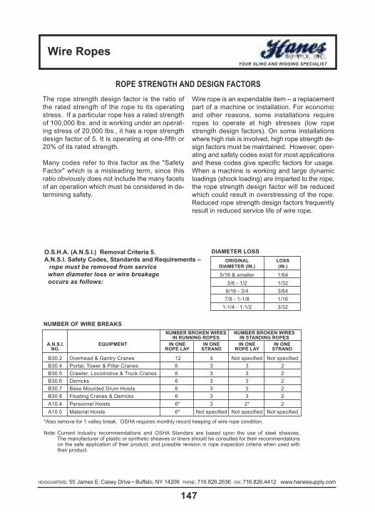
Wire RopesYOUR SLING AND RIGGING SPECIALIST
147HEADQUARTERS: 55 James E. Casey Drive • Buffalo, NY 14206 PHONE: 716.826.2636 FAX: 716.826.4412 www.hanessupply.com
The rope strength design factor is the ratio ofthe rated strength of the rope to its operatingstress. If a particular rope has a rated strengthof 100,000 lbs. and is working under an operat-ing stress of 20,000 lbs., it has a rope strengthdesign factor of 5. It is operating at one-fifth or20% of its rated strength.
Many codes refer to this factor as the "SafetyFactor" which is a misleading term, since thisratio obviously does not include the many facetsof an operation which must be considered in de-termining safety.
nUMbeR bRoken WIRes nUMbeR bRoken WIResIn RUnnInG RoPes In stanDInG RoPes
a.n.s.I. eQUIPMent In one In one In one In oneno. RoPe laY stRanD RoPe laY stRanD
B30.2 Overhead & Gantry Cranes 12 4 Not specified Not specifiedB30.4 Portal, Tower & Pillar Cranes 6 3 3 2B30.5 Crawler, Locomotive & Truck Cranes 6 3 3 2B30.6 Derricks 6 3 3 2B30.7 Base Mounted Drum Hoists 6 3 3 2B30.8 Floating Cranes & Derricks 6 3 3 2A10.4 Personnel Hoists 6* 3 2* 2A10.5 Material Hoists 6* Not specified Not specified Not specified
nUMbeR of WIRe bReaks
Wire rope is an expendable item – a replacementpart of a machine or installation. For economicand other reasons, some installations requireropes to operate at high stresses (low ropestrength design factors). On some installationswhere high risk is involved, high rope strength de-sign factors must be maintained. However, oper-ating and safety codes exist for most applicationsand these codes give specific factors for usage.When a machine is working and large dynamicloadings (shock loading) are imparted to the rope,the rope strength design factor will be reducedwhich could result in overstressing of the rope.Reduced rope strength design factors frequentlyresult in reduced service life of wire rope.
o.s.H.a. (a.n.s.I.) Removal criteria 5.a.n.s.I. safety codes, standards and Requirements –
rope must be removed from servicewhen diameter loss or wire breakageoccurs as follows:
oRIGInal lossDIaMeteR (In.) (In.)
5/16 & smaller 1/643/8 - 1/2 1/32
9/16 - 3/4 3/647/8 - 1-1/8 1/16
1-1/4 - 1-1/2 3/32
DIaMeteR loss
*Also remove for 1 valley break. OSHA requires monthly record keeping of wire rope condition.
Note: Current industry recommendations and OSHA Standars are based upon the use of steel sheaves. The manufacturer of plastic or synthetic sheaves or liners should be consulted for their recommendationson the safe application of their product, and possible revision in rope inspection criteria when used withtheir product.
ROPE STRENGTH AND DESIGN FACTORS

Wire RopesYOUR SLING AND RIGGING SPECIALIST
148HEADQUARTERS: 55 James E. Casey Drive • Buffalo, NY 14206 PHONE: 716.826.2636 FAX: 716.826.4412 www.hanessupply.com HEADQUARTERS: 55 James E. Casey Drive • Buffalo, NY 14206 PHONE: 716.826.2636 FAX: 716.826.4412 www.hanessupply.com
UNDERSTAND WHAT THE "LAYS" OF WIREROPE MEAN"Lay" of a wire rope is simply a description of the waywires and strands are placed during construction. Rightlay and left lay refer to the direction of strands. Rightlay means that the strands pass from left to right acrossthe rope. Left lay means just the opposite; strands passfrom right to left.
Regular lay and lang lay describe the way wires areplaced within each strand. Regular lay means that wiresin the strands are laid opposite in direction to the lay ofthe strands. Lang lay means that wires are laid in thesame direction as the lay of the strands.
Most of the wire rope used is right lay, regular lay. Thisspecification has the widest range of applications andmeets the requirements of most equipment. In fact,other lay specifications are considered exceptions andmust be requested when ordering.
HERE ARE SOME EXCEPTIONSLang lay is recommended for many excavating, con-struction, and mining applications, including draglines,hoist lines, dredgelines and other similar lines. Here'swhy. Lang lay ropes are more flexible than regular layropes. They also have greater wearing surface per wirethan regular lay ropes.
Where properly recommended, installed and used, langlay ropes can be used to greater advantage than regularlay ropes. However, lang lay ropes are more susceptible
ROPE STRENGTH AND DESIGN FACTORS
to the abuses of bending over small diameter sheaves,pinching in undersize sheave grooves, crushing whenwinding on drums, and failing due to excessive rotation.Left lay rope has greatest usage in oil fields on rod andtubing lines, blast hole rigs, and spudders where rotationof right lay rope would loosen couplings. The rotation ofa left lay rope tightens a standard coupling.
A wire rope is a piece of flexible, multi-wired, strandedmachinery made of many precision parts.
Usually a wire rope consists of a core member, aroundwhich a number of multi-wired strands are "laid" or he-lically bent. There are two general types of cores forwire rope – fiber cores and wire cores. The fiber coremay be made from natural or synthetic fibers. The wirecore can be an Independent Wire Core (IWRC), orStrand Core (SC).
The purpose of the core is to provide support and main-tain the position of the outer strands during operation.
Any number of multi-wired strands may be laid aroundthe core. The most popular arrangement is six strandsaround the core, as this combination gives the best bal-ance.
The number of wires per strand may vary from 3 to 91,with the majority or wire ropes falling into the 7-wire, 19-wire, or 36 wire strand categories.
RIGHt laY ReGUlaR laY
left laY ReGUlaR laY
RIGHt laY lanG laY
left laY lanG laY
LENGTH OF SERVICE DEPENDS ON HOW YOU TREAT YOUR WIRE ROPES.

basic lift engineeringYOUR SLING AND RIGGING SPECIALIST
149HEADQUARTERS: 55 James E. Casey Drive • Buffalo, NY 14206 PHONE: 716.826.2636 FAX: 716.826.4412 www.hanessupply.com
stRaIGHt oR VeRtIcal, attach-ment, is simply using a sling to connecta lifting hook to a load. Full rated liftingcapacity of the sling may be utilized,but must not be exceeded. Whenevera single sling is used in this manner, atagline should be used to prevent loadrotation which may cause damage tothe sling.
When two or more slings are attachedto the same lifting hook in straight orvertical manner, the total hitch be-comes, in effect, a lifting bridle, and theload is distributed among the individualslings.
cHokeR hitches reduce lifting capa-bility of a sling, since this method of rig-ging affects ability of the wire ropecomponents to adjust during the lift. Achoker is used when the load will notbe seriously damaged by the slingbody – or the sling damaged by theload, and when the lift requires thesling to snug up against the load.
The diameter of the bend where the slingcontacts the load should keep the pointof choke against the sling BODY – neveragainst a splice or the base of the eye.When a choke is used, the sling ratedcapacity must be adjusted downward tocompensate for loss of capability.
A choker hitch should be pulled tight be-fore a lift is made – NOT PULLEDDOWN DURING THE LIFT. It is alsodangerous to use only one choker hitchto lift a load which might shift or slide outof the choke.
basket hitches distribute a load be-tween the two legs of a sling – withinlimitations described below. Capacity ofa sling used in a basket is affected bythe bend, or curvature, where the slingbody comes in contact with the load –just as any sling is affected and limitedby bending action, as over a sheave.
EVERY LIFT USES 1 OF 3 BASIC HITCHES
CALCULATING THE LOAD ON EACH LEG OF A SLINGAs the horizontal angle between thelegs of a sling decreases, the loadon each leg increases. The effect isthe same whether a single sling isused as a basket, or two slings areused with each in a straight pull, aswith a 2-legged bridle.
Anytime pull is exerted at an angle on aleg – or legs – of a sling, the load perleg can be determined by using thedata in the table at right. Proceed asfollows to calculate this load – and determine the rated capacity requiredof the sling, or slings, needed for a lift.
1. First, divide the total load to be lifted by the number of legs to be used. This provides the load per leg if the lift were being made with all legs lifting vertically.
2. Determine the angle.
3. Then MULTIPLY the load per leg (as computed inNo. 1 above) by the Load Factor for the leg anglebeing used (from the table below) – to computethe ACTUAL LOAD on each leg for this lift andangle. THE ACTUAL LOAD MUST NOT EXCEEDTHE RATED SLING CAPACITY.
Thus, in drawing three (sling angle at 60°):1000 ÷ 2 = 500 (Load Per Leg if vertical lift)500 x 1.154 = 577 lbs. = ACTUAL LOAD on each leg at the 60° HORIZ angle being used.
In drawing four (sling angle of 45°):1000 ÷ 2 = 500 (Load Per Leg if a vertical lift)500 x 1.414 = 70 lbs. = ACTUAL LOAD on each leg at the 45° HORIZ angle being used.
leG anGle loaD(DeGRees) factoR
90° 1.00085° 1.00380° 1.01575° 1.03570° 1.06465° 1.10360° 1.15455° 1.22050° 1.30545° 1.41435° 1.56630° 2.000
stRaIGHtcHokeR
basket
loaD
loaDloaD
1000 LBS
500
LBS
.
500
LBS
.
1000 LBS 1000 LBS 1000 LBS
1000
LB
S
1000
LB
S
1000
LB
S
518
LBS
518 LBS
577
LBS
577 LBS
707 L
BS 707 LBS90° 75° 60° 45°
Rated Capacity AdjustmentFor Choker Hitches
ANGLEOF
CHOKEIN
DEGREES
PERCENTOF SLING
RATEDCAPACITY
APPLICABLE
120-18090-11960-8930-59
0-29
100%87%74%62%49%
When a choke is drawn down tight against a load,or a side pull is exerted resulting in an angle of lessthan 120°, an adjustment must be made for furtherreduction of the sling rated capacity.

basic lift engineeringYOUR SLING AND RIGGING SPECIALIST
150HEADQUARTERS: 55 James E. Casey Drive • Buffalo, NY 14206 PHONE: 716.826.2636 FAX: 716.826.4412 www.hanessupply.com HEADQUARTERS: 55 James E. Casey Drive • Buffalo, NY 14206 PHONE: 716.826.2636 FAX: 716.826.4412 www.hanessupply.com
effect of anGlesVarious sling manufacturers refer in theirspecification tables to leg angles of slingsduring lifts – since these angles have a di-rect relationship to lifting capability of asling. Regardless of how the sling anglemay be stated, or the method used to com-pute stress in a sling leg, the sling is thesame. Capacity does not change – butstresses on sling legs change with riggingangles.
Much misunderstanding results becausethe carrying capacity of a sling leg is re-duced by the rigging angle. What happensis that the operator is lifting the loadstraight up (vertical) while the legs arepulling at an angle, thereby causing a dis-advantage.
For quick figuring in the shop, a 60-degreeleg angle causes a loss in lifting capacityof 15%... a 45-degree angle reduces ca-pacity by 30%... and a 30-degree angle,50%. This rule of thumb is not 100% accu-rate, but is easy to remember and slightlyon the safe side.
It is always good practice, within limits, tokeep the sling leg angle as large as possi-ble. The length and width of the load slinglength, and available headroom are deter-mining factors in this sling angle.
It is neither economical nor good practice toexceed a 45-degree sling leg angle.
Angles less than 45 degrees not only buildup tension in the sling legs out of all propor-tion to the weight of the load, they also cre-ate a much greater "in-pull" on the ends ofthe load. This produces eccentrically loadedcolumn effect, as an engineer would de-scribe it – meaning simply that long, slenderobjects have a tendency to buckle. Anglesless than 45 degrees indicate some thoughtshould be given to the use of a lifting beamor other device in connection with the lift.
Studying typical sling charts readily revealsthat lifting capacities on slings are mislead-ing unless the sling angle is stated. Thesame sling that will handle 10 tons at an 85-degree leg angle will only handle 5 tons ifthis angle is decreased to 30 degrees.
GooD slInG PRactIceRegardless of what type of sling may be em-ployed, there are accepted good workingrules which will help increase useful sling life– as well as improve safety. These include:1. Use the proper sling for the lift. Whether
Twin-Path, Web, Chain, or Wire Rope, theproper sling is the one with the best com-bination of work and handling feature – ofthe proper length and rated capacity forthe situation.
selectInG a slInG
The following is presented as a guide onlyto help in selection of a sling for a lift.1. Determine the Load: The weight of the
load must be known. This is always thestarting point.
2. Decide the Hitch: Shape and bulk of theload must be accommodated as well asweight. Determine whether a straight at-tachment at some point on the load, achoker around the load, or some form ofbasket hitch will best control the loadduring the lift.
3. Adequacy of Lifting Device: The liftingdevice must have adequate capacity formaking the lift, and provide any maneu-verability required once the load ishoisted.
4. Room to Lift: Make certain the lifting de-vice has sufficient headroom to raise theload to the height required. Headroomwill affect the length of sling.
5. Length of Sling: By applying your deci-sion on the type of hitch to knowledge ofthe headroom offered by the lifting de-vice, the length of sling can be calcu-lated.
6. Use Rated Capacity Chart: Always dou-ble-check that the sling type and capacityyou choose, when rigged at the angle de-termined by the length of the sling, or thespecific type of hitch, will handle the load.
Attaching the sling and completing the liftshould be an orderly procedure without "sur-prises" when these steps have been fol-lowed. Two further precautions should benoted, however.
First, plan to protect both load and sling fromdamage at sharp corners, etc. Cornermax™and Synthetic Armor Wear Pads should beprovided at the lift site. A protective padshould be used anytime a sling passesaround a sharp corner.
Last – by no means unimportant by beinglast – every sling should be visually exam-ined from end to end BEFORE EVERY LIFT.It must always be kept in mind that the man-ufacturer's Rated Capacity applies only to anew sling in "unused" condition. A slingshould be carefully examined to determinethat it is in as nearly new condition as prac-ticable before each lift.
There are specific standards on the use andcare of slings in industries such as shippingand construction, and these provide someguidance for sling inspectors. Consensusstandards published as ANSI B30.9 are par-ticularly helpful.
ANSI Standard B30.9 specifies that a wirerope sling should be removed form serviceany time any of the following conditions aredetected:
1. Ten randomly distributed broken wires inone rope lay, or five broken wires in onestrand in one rope lay.
2. Kinking, crushing, bird caging or anyother damage resulting in distortion ofthe wire rope structure.
3. Evidence of heat damage.4. End attachments that are cracked, de-
formed, or worn.5. Hooks that have been opened more than
15% of the normal throat opening meas-ured at the narrowest point, or twistedmore than 10 degrees from the plane ofthe unbent hook.
6. Corrosion of the rope or end attach-ments.
It is apparent from the foregoing that in-spection of a wire rope sling to meet theseremoval criteria requires more than a ca-sual understanding of wire rope design andmanufacture, and the responsibility fordaily inspections must be in the hands oftrained personnel.
Most of the foregoing applies equally to anytype of sling and careful inspection by atrained inspector is necessary for safe slinguse. If you require training for any type ofsling inspection, contact Hanes Supply formore information.
2. Start and stop slowly. Crane hooksshould be raised slowly until the sling be-comes taut and the load is suspended.Lifting or lowering speed should be in-creased or decreased gradually. Suddenstarts or stops place heavier loads on asling – comparable to jamming thebrakes on a speeding automobile. A ruleof thumb: Shock loads can double thestress on a sling.
3. If possible, set the load on blocks.Pulling a sling from under a load causesabrasion and "curling" – making the slingharder to handle on the next lift, while re-ducing strength through loss of metal.
4. Sharp corners cut slings. Use protectorarcs, Cornermax™ and Synthetic ArmorWear Pads between sharp corners andthe sling body.
5. Store in a dry room. Moisture is a natu-ral enemy of wire rope – as are acidfumes and other caustic gases.
6. Avoid handling hot material or objects indirect contact with the sling. Strengthgoes down as temperature goes up!
7. Dropping casting, tools or heavy objectson slings, or running over them withtrucks, can cause damage. Always hangslings when not in use.
8. Use hooks properly. "Point loading" re-duces hook capacity. Pull should bestraight in the line of lift.

Wire RopesYOUR SLING AND RIGGING SPECIALIST
151HEADQUARTERS: 55 James E. Casey Drive • Buffalo, NY 14206 PHONE: 716.826.2636 FAX: 716.826.4412 www.hanessupply.com
block tWIstInGBlock twisting or "cabling" is one of themost frequently encountered wire ropeproblems in the construction field. Whenthis problem occurs, the wire rope is mostoften blamed, and other equally importantfactors in the operation are overlooked.
Personnel experienced with handling ofwire rope know that conventional wireropes will twist or unlay slightly, when aload is applied. In a reeved hoisting sys-tem, subjected to loading and unloadingsuch as a load hoisting line, this results inblock twisting and possibly distortion of thewire rope. Cabling of the block most fre-quently occurs as the load in the wire ropeis released, and the "falls" are in a loweredposition. Cabling may be considered as thetwisting of the block beyond one-half of arevolution (180° twisting) of the travelingblock. When this condition occurs, the op-erator shows good judgment in not makingadditional lifts, until the conditions causingthe problem are corrected.
The following machine and site conditionsshould be investigated for possible im-provement in block twisting.1. Reduced wire rope length. Longer rope
lengths cause more twisting than shortrope lengths. This applies particularly tothe amount of wire rope in the "falls."
2. Reduce the amount of load lifted. Heav-ily loaded ropes have more torque andtwist than lightly loaded ropes. This con-dition would also apply to the speed of
loading or "shock" loading, since this con-dition also causes higher wire rope load-ing.
3. Eliminate "odd-part" reeving, where thewire rope "dead-end" is on the travelingblock. Wire rope torque, from the applica-tion of load, is greatest at the rope dead-end.
4. Relocate the rope dead-end at the boom,in order to increase the separation be-tween the dead-end and the other ropeparts. This applies a stabilizing load di-rectly to the traveling block. The originalequipment manufacturer should be con-sulted before making this modification.
5. Increase sheave size. This increases theamount of separation between wire ropeparts and may improve the situation byapplying stabilizing loads and reducingthe amount of rope torque transmitted tothe traveling block.
6. Restrain the twisting block with a "tag"line. One or more of the foregoing sug-gestions may eliminate the problem with-out resorting to "specialized" wire ropewhich may not only be difficult to locatebut expensive as well.
The use of special "rotation resistant" wireropes will not likely be required unless theintended length of rope "falls" exceeds 100feet, or the length of the load hoisting lineexceeds 600 feet. In the event these latterconditions exist, the user should also antici-pate using a combination of the "rotation re-sistant" wire rope and the foregoing fieldsuggestions for the more severe problems.
PHYsIcal PRoPeRtIeselastIc PRoPeRtIes ofWIRe RoPeThe following discussion relates to con-ventional 6- or 8-strand ropes that have ei-ther fiber or steel cores; it is not applicableto rotation-resistant ropes since these con-stitute a separate case.Wire rope is an elastic member; it stretchesor elongates under load. This stretch derives from two sources:
1. constructional, and2. elastic.
In actuality, there may be a third source ofstretch – a result of the rope rotating on itsown axis. Such elongation, which mayoccur either as a result of using a swivel,or from the effect of a free-turning load, isbrought about by the unlaying of the ropestrands. Because the third source is a sub-ject that is beyond the scope of this publi-cation, discussion will be directed toconstructional and elastic stretch.
constRUctIonal stRetcHWhen a load is applied to wire rope, the helically-laid wires and strands act in a constricting manner thereby compressingthe core and bringing all the rope elementsinto closer contact. The result is a slight re-duction in diameter and an accompanyinglengthening of the rope.Constructional stretch is influenced by thefollowing factors:
1. type of core (fiber or steel),2. rope construction (6 x 7, 6 x 25 FW,
6 x 41 WS, 8 x 19 S, etc.),3. length of lay4. material.
Ropes with wire strand core (WSC) or independent wire rope core (IWRC) haveless constructional stretch than those withfiber core (FC). The reason for this is thefact that the steel cannot compress asmuch as the fiber core.Usually, constructional stretch will cease atan early stage in the rope's life. However,some fiber core ropes, if lightly loaded (asin the case of elevator ropes), may displaya degree of constructional stretch over aconsiderable portion of their life.A definite value for determining construc-tional stretch cannot be assigned since itis influenced by several factors. The fol-lowing table gives some idea of the ap-proximate stretch as a percentage of ropeunder load.
RoPe constRUctIon aPPRoX. stRetcH*
6 strand FC 1/2% - 3/4%6 strand IWRC 1/4% - 1/2%8 strand FC 3/4% - 1%
*Varies with the magnitude of the loading.
RoPe zeRo tHRoUGH 20% 21 to 65% classIfIcatIon loaDInG loaDInG*
6 x 7 with fiber core 11,700,000 13,000,0006 x 19 with fiber core 10,800,000 12,000,0006 x 36 with fiber core 9,900,000 11,000,0008 x 19 with fiber core 8,100,000 9,000,0006 x 19 with IWRC 13,500,000 15,000,0006 x 36 with IWRC 12,600,000 14,000,000
*Applicable to new rope, i.e., not previously loaded.
elastIc stRetcH
Elastic stretch results from recoverable deformation of the metal itself. Here, again, a quan-tity cannot be precisely calculated. However, the following equation can provide a reason-able approximation for a good many situations.
Change in load (lb.) x Length (ft.)Changes in length (ft.) =
Area (in.2) x Modulus of Elasticity (psi)
The modulus of elasticity is given below.
aPPRoXIMate MoDUlUs of elastIcItY(PoUnDs PeR sQUaRe IncH)

General InformationYOUR SLING AND RIGGING SPECIALIST
152HEADQUARTERS: 55 James E. Casey Drive • Buffalo, NY 14206 PHONE: 716.826.2636 FAX: 716.826.4412 www.hanessupply.com HEADQUARTERS: 55 James E. Casey Drive • Buffalo, NY 14206 PHONE: 716.826.2636 FAX: 716.826.4412 www.hanessupply.com
VaRYInG sHeaVe ReVolUtIons In a PaIR of tackle blocks
To raise a load one foot, the lower block must be raised one foot, and in accomplishingthis, each working rope must be shortened one foot.
In the example above, Ropes 1, 2, 3, etc., must be shortened one foot to raise the loadone foot. Assuming that the circumference of each sheave is one foot, Sheave No.1must make one revolution to shorten Rope No. 1; Sheave No. 2 must make one rev-olution to take up the one foot slack form Rope No. 1 and one additional revolution toshorten Rope No. 2; Sheave No. 3 must make two revolutions to take up the two feet ofslack from Ropes 1 and 2 and one additional revolution to shorten Rope No. 3, etc. foreach succeeding sheave.
Viz: Rope No. 1 must travel one foot on Sheave No. 1.Rope No. 2 must travel two feet on Sheave No. 2.Rope No. 3 must travel three feet on Sheave No. 3.Rope No. 4 must travel four feet on Sheave No. 4.Rope No. 5 must travel five feet on Sheave No. 5.
Therefore, all the sheaves in a set of blocks revolve at different rates of speed. Sheave No. 2 rotates twice as fast asNo. 1, Sheave No. 3 rotates three times as fast as No.1, Sheave No. 4 four times as fast as No. 1, etc. Consequentlythe sheaves nearest the lead line, rotating at higher rates of speed, wear out more rapidly.
All sheaves should be kept well lubricated when in operation to reduce friction and wear.
edges of the block shell.
To reeve by this method, the two blocks should beplaced so that the sheaves in the upper block are at rightangles to those in the lower one, as shown in the fol-lowing illustrations. Start reeving with the becket, orstanding end, of the rope.
It is good practice to use a shackleblock as the upper one of a pair and ahook block as the lower one. A shacklewould prevent any accidental disen-gagement of the block from its attach-ing point in the event of an unusualmovement of the attaching point orblock. The lower block having a hook ismore readily attached or detached fromthe load. See Figures 1 through 5.
In reeving a pair of tackle blocks, one of which has morethan two sheaves, the hoisting rope should lead fromone of the center sheaves of the upper block.
When so reeved, the hoisting strain comes on the cen-ter of the blocks and they are prevented from toppling,with consequent injury to the rope by cutting across the
THE REEVING OF TACKLE BLOCKS
fIGURe 1 fIGURe 2 fIGURe 3 fIGURe 4
fIGURe 5
DoUble anDDoUble
tRIPle anDDoUble
tRIPle anDtRIPle
QUaDRUPleanD tRIPle
sHeaVeno. 5
sHeaVeno. 1
sHeaVeno. 3
sHeaVeno. 4
sHeaVeno. 2

General InformationYOUR SLING AND RIGGING SPECIALIST
153HEADQUARTERS: 55 James E. Casey Drive • Buffalo, NY 14206 PHONE: 716.826.2636 FAX: 716.826.4412 www.hanessupply.com
RatIo foR RatIo foRnUMbeR bRonze antI-fRIctIon
of PaRts bUsHeD beaRInGof lIne sHeaVes sHeaVes
1 .96 .982 1.87 1.943 2.75 2.884 3.59 3.815 4.39 4.716 5.16 5.607 5.90 6.478 6.60 7.329 7.27 8.16
10 7.91 8.9811 8.52 9.7912 9.11 10.613 9.68 11.414 10.2 12.115 10.7 12.916 11.2 13.617 11.7 14.318 12.2 15.019 12.6 15.720 13.0 16.421 13.4 17.022 13.8 17.723 14.2 18.324 14.5 18.9
HOW TO FIGURE LINE PARTS
To help figure the number of parts of line to be used for agiven load or the line pull required for a given load, thefollowing ratio table is provided with examples of how touse it:
1PaRt
of lIne
2PaRts
of lIne
3PaRts
of lIne
4PaRts
of lIne
5PaRts
of lIne
USING THE RATIO TABLE RATIO FORMULA
example:To find the number of parts of line needed whenweight of load and single line pull is established.
Sample Problem:72,480 lbs. (load to be lifted)8,000 lbs. (single line pull) = 9.06 RATIO
Refer to ratio 9.06 in table or number nearest toit, then check column under heading "Numberof Parts of Line"... 12 parts of line to be used forthis load.
example:To find single line pull needed when weight ofload and number of parts of line are estab-lished.
Sample Problem:68,000 lbs. (load to be lifted)6.60 (ratio of 8 part line) = 10,300 lbs. (single line pull)
10,300 lbs. single line pull required to lift thisload on 8 parts of line.
TOTAL LOAD TO BE LIFTED= RATIO
SINGLE LINE PULL IN POUNDS

General InformationYOUR SLING AND RIGGING SPECIALIST
154HEADQUARTERS: 55 James E. Casey Drive • Buffalo, NY 14206 PHONE: 716.826.2636 FAX: 716.826.4412 www.hanessupply.com HEADQUARTERS: 55 James E. Casey Drive • Buffalo, NY 14206 PHONE: 716.826.2636 FAX: 716.826.4412 www.hanessupply.com
LOADS ON BLOCKS
The Rated Load Values for blocks shown in Crosby Group lit-erature are shown as "Working Loads," "Safe Working Load"and "Resultant Safe Working Load"; and all these terms aredefined as the maximum amount of total load that should beexerted on the block and its fitting, the fitting being a hook,shackle, eye, loop, etc.
It must be recognized that this total load value MAY BE DIF-FERENT than the weight being lifted or pulled by a hoistingor hauling system and, therefore, it is necessary to determinethe total load being imposed on each block in the system in
order to properly determine the rated capacity block to beused.
A single sheave block that is used to change direction of aload line can be subjected to total loads GREATLY DIFFER-ENT than the weight being lifted or pulled. The amount of totalload changes with the angle between the incoming and de-parting lines to the block.
The following chart indicates the factor that is multiplied bythe line pull to obtain the total load on the block:
anGle factoR anGle factoR anGle factoR
0° 2.00 60° 1.73 130° .8410° 1.99 70° 1.64 135° .7620° 1.97 80° 1.53 140° .6830° 1.93 90° 1.41 150° .5240° 1.87 100° 1.29 160° .3545° 1.84 110° 1.15 170° .1750° 1.81 120° 1.00 180° .00
example: A gin pole truck being used to lift a weight of 1,000 lbs.
There is no mechanical advantage to a single part load linesystem, so, whinch line pull is equal to 1,000 lbs. or the weightbeing lifted.
Total load on snatch block shown as A equals 1,000 lbs. timesangle factor for 50°.
Total load on A = 1,000 x 1.81 = 1,1810 lbs.
Total load on toggle block shown as B equals 1,000 lbs. timesangle factor for 135°.
Total load on B = 1,000 x .76 = 760 lbs.
total loaD
example: Hoisting system using a traveling block to lift a weightof 1,000 lbs.
The mechanical advantage at the traveling block C is 2 because2 parts of a load line support the 1,000 lbs. weight; so, the linepull equals the 1,000 lbs. divided by 2 or 500 lbs.
Total load on traveling block shown as C equals 500 lbs. timesangle factor for 0°.
Total Load on C = 500 x 2.00 = 1,000 lbs.
Total load on stationary block shown as D equals the dead endload of 500 lbs. plus the line pull of 500 lbs. times the angle fac-tor for 40°.
Total Load on E = 500 x .84 = 420 lbs.
Total load on block shown as F equals 500 lbs. times the anglefactor for 90°.
Total Load on F = 500 x 1.41 = 705 lbs.
lIne PUll lIne PUll
anGle
WIncHlInePUll
135°50°
a
b1000 lbs
1000 lbs
130°
50°
40°
ef
c
D
0°
General InformationYOUR SLING AND RIGGING SPECIALIST
155HEADQUARTERS: 55 James E. Casey Drive • Buffalo, NY 14206 PHONE: 716.826.2636 FAX: 716.826.4412 www.hanessupply.com
DEFINITIONS OF TERMS
abrasion: The mechanical wearing of surface resulting from frictional contact with materials or objects.
breaking strength: That total force (lbs. or kg.) at which the sling fails. The total weight strain whichcan be applied before failure. Usually at five times the rated capacity.
competent Person: A person designated for inspection who is trained, qualified by knowledge andpractical experience and the necessary instructions to enable the required test or examination to becarried out.
twin-Path® core: The load bering multiple fibers of polyester, aramids, or K-Spec™ which, whenwound into the seamless tubes, become the load bearing yarns of the sling. If other materials areused, follow the manufacturers recommendations.
twin-Path® cover: The seamless tubes, usually at least two separate and contrasting colors foreasier inspection that contain the cores. Covers may be of polyester, Covermax nylon, or aramidsdepending on the desired finished characteristics of the product.
elongation: The measurement of stretch, expressed as a percentage of the finished length.
fitting: A load bearing metal component which is fitted to the sling. Can be of steel, aluminum orother material that will sustain the rated capacity of the sling.
Hitch/Vertical: A method of attachment whereby the sling extends from the crane hook to theload in a straight connection.
Hitch/choker: The sling is passed around the load and back through itself and is connectedto the crane hook. The sling then tightens around the load when it is strained.
Hitch/basket: The sling is passed from the crane hook around the load and attached to thecrane hook.
length: The distance between bearing points of the sling.
Proof load test: A non-destructive load test usually to twice the rated capacity of the sling.
synthetic fiber: Man-made material used for the cover, the core and the thread of the Twin-Path®
sling products.
tattle-tails: Tell-Tails which extend past the tag area of Twin-Path® slings. Extension of the loadcore yarns. When the sling is stretched beyond its elastic limit, they shrink and eventually disappearunder the tag. Take out of service if less than 1/2" is exposed.
thread: The synthetic yarn which is used to sew the sling covers and tag and to provide the stitchwhich separates the individual load cores.
twin-Path®: A patented and trademarked product which is composed of two separate load cores andtwo contrasting color covers.

General InformationYOUR SLING AND RIGGING SPECIALIST
156HEADQUARTERS: 55 James E. Casey Drive • Buffalo, NY 14206 PHONE: 716.826.2636 FAX: 716.826.4412 www.hanessupply.com HEADQUARTERS: 55 James E. Casey Drive • Buffalo, NY 14206 PHONE: 716.826.2636 FAX: 716.826.4412 www.hanessupply.com
Rated load: The maximum recommended load that should be exerted on the item.The following terms are also used for the term Rated Load: "Working Load,""Working Load Limit," and "Resultant Working Load." All rated load values, unless noted otherwise, are for in-line pull with respect to the centerline of theitem.
Proof load: The average load to which an item may be subjected before visual deformationoccurs or a load that is applied in the performance of a proof test.
Proof test: A term designating a tensile test applied to the item for the sole purpose of detecting injurious defects in the material or manufacture.
Ultimate load: The average load at which the item is being tested fails or no longer supportsthe load.
shock load: A resulting load from the rapid change of movement, such as impacting or jerk-ing, or a static load. A Shock Load is generally significantly greater than thestatic load.
Design factor: An industry term denoting theoretical reserve capability. Usually computed dividing the catalog stated ultimate load by the catalog stated working load limitand generally expressed as a ratio, for example: 5 to 1.
DEFINITIONS OF TERMS
CAUTIONS OR WARNINGS
All ratings shown in this literature are based upon the items being new or "in as new" condition.Catalog ratings are considered to be the greatest load that should be applied to the item; therefore,any shock loading must be considered when selecting the item for use in a system.
The products shown in this literature are subject to wear, misuse, overloading, corrosion, deforma-tion, intentional alteration and other usage factors which may necessitate a reduction in the prod-uct's Rated Capacity or a reduction in its Design Factor. Therefore, it is recommended that allproducts be regularly inspected to determine their condition as a basis for deciding if the productmay continue to be used at the catalog assigned WL, a reduced WL, a reduced design factor, or re-moved from service.
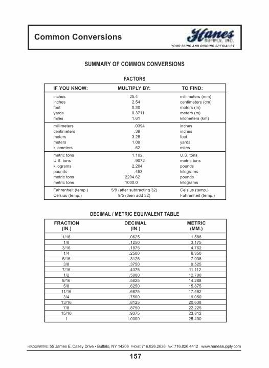
common conversionsYOUR SLING AND RIGGING SPECIALIST
157HEADQUARTERS: 55 James E. Casey Drive • Buffalo, NY 14206 PHONE: 716.826.2636 FAX: 716.826.4412 www.hanessupply.com
If YoU knoW: MUltIPlY bY: to fInD:inches 25.4 millimeters (mm)inches 2.54 centimeters (cm)feet 0.30 meters (m)yards 0.3711 meters (m)miles 1.61 kilometers (km)
millimeters .0394 inchescentimeters .39 inchesmeters 3.28 feetmeters 1.09 yardskilometers .62 miles
metric tons 1.102 U.S. tonsU.S. tons .9072 metric tonskilograms 2.204 poundspounds .453 kilogramsmetric tons 2204.62 poundsmetric tons 1000.0 kilograms
Fahrenheit (temp.) 5/9 (after subtracting 32) Celsius (temp.)Celsius (temp.) 9/5 (then add 32) Fahrenheit (temp.)
SUMMARY OF COMMON CONVERSIONS
FACTORS
fRactIon DecIMal MetRIc(In.) (In.) (MM.)1/16 .0625 1.5881/8 .1250 3.175
3/16 .1875 4.7621/4 .2500 6.350
5/16 .3125 7.9383/8 .3750 9.525
7/16 .4375 11.1121/2 .5000 12.700
9/16 .5625 14.2885/8 .6250 15.875
11/16 .6875 17.4623/4 .7500 19.050
13/16 .8125 20.6387/8 .8750 22.225
15/16 .9375 23.8121 1.0000 25.400
DECIMAL / METRIC EQUIVALENT TABLE

Lift EngineeringYOUR SLING AND RIGGING SPECIALIST
158HEADQUARTERS: 55 James E. Casey Drive • Buffalo, NY 14206 PHONE: 716.826.2636 FAX: 716.826.4412 www.hanessupply.com
LOAD ANGLE FACTORS
TENSION IN OVERHEAD HOISTS
OFF-SET CENTER OF GRAVITY (SHARE OF THE LOAD)
OFF-LEVEL LIFT POINTS
To find c (hypotenuse)Given: a2 + b2 = c2
Example: 42 + 32 = c2; 16 + 9 = c2; 25 = 5
L 15— = LAF (Load Angle Factor) Example: — = 1.5 (LAF)H 10
LTension in L = — x L's share of the loadH
15Tension in L = — x 5,000; 1.5 x 5,000 Ten. = 7,500 lbs.10
a
b
c
6Ten. in A = — x 3,000 Ten. in A = 9,000 lbs.2
(As load moves, tension changes)
Lift Point A
7 + 3 = 10, — = .7010
.70 x 10,000 = 7,000 lbs.
Inverse Proportion To Distance
Lift Point B
7 + 3 = 10, — = .3010
.30 x 10,000 = 3,000 lbs.
W x D2 x L1TL1 =(D2 x H1) + (D1 x H2)
W x D1 x L2TL2 =(D2 x H1) + (D1 x H2)
LEGENDW = Load WeightL1 = Length Leg 1L2 = Length Leg 2H1 = Vertical Height 1H2 = Vertical Height 2D1 = Horizontal Distance 1D2 = Horizontal Distance 2
5,000 lbs. 5,000 lbs.
LH
10,000 lbs.
H = 10' L = 15'
A B6' 6'2'
6,000 lbs.
A B
3' 7'
10,000 lbs.
L1
L2
H1
H2
D1 D2

Weights of MaterialYOUR SLING AND RIGGING SPECIALIST
159HEADQUARTERS: 55 James E. Casey Drive • Buffalo, NY 14206 PHONE: 716.826.2636 FAX: 716.826.4412 www.hanessupply.com
foRMUlas anD InfoRMatIon
H = Height W = Width l = Length d = diameter r = radius (1/2 dia.)p = 3.14 (rounded 3.15) [area of a square or rectangle = HW]
[Vol of cube = HWL] [Circumference of circle = pd] [area of a circle = pr2
or the approximate area of a circle = 80% of the dia2 (dia x dia x .80)]
MateRIals anD lIQUIDs – PoUnDs/cU. ft.
Aluminum 165 Granite, Solid 168Asbestos 153 Iron Casting 450Asphalt 81 Lead 710Brass 524 Limestone, Solid 163Brick, Soft 100 Lumber – Fir 32Brick, Medium 115 Lumber – Oak 62Brick, Hard 130 Lumber – RR Ties 50Bronze 534 Marble, Solid 160Coal 56 Oil, Motor 60Concrete, Reinforced 150 Paper 75Copper 556 Portland Cement, Loose 94Crushed Rock 95 Portland Cement, Set 183Diesel 52 River Sand 120Dry Earth, Loose 75 Rubber 94Dry Earth, Packed 95 Steel 490Gasoline 45 Water, Fresh 63Glass 161 Zinc 437
MateRIals – PoUnDs/sQ. ft.
Steel Plate Aluminum Plate1/8" 5 1/8" 1.751/4" 10 1/4" 3.501/2" 20 1/2" 7.003/4" 30 3/4" 10.501" 40 1" 14.00

Usa standardcrane Hand signals
YOUR SLING AND RIGGING SPECIALIST
160HEADQUARTERS: 55 James E. Casey Drive • Buffalo, NY 14206 PHONE: 716.826.2636 FAX: 716.826.4412 www.hanessupply.com
Use Main Hoist.Tap fist on head;then use regular signals.
Use Whipline.(Auxiliary Hoist).Tap elbow with onehand, then use regular signals.
Raise Boom. Armextended, fingersclosed, thumb point-ing upward.
Lower Boom. Armextended, fingersclosed, thumb pointing downward.
Travel. Arm extendedforward, hand openand slightly raised,make pushing motionindirection of travel.
Swing. Arm ex-tended, point with finger in direction of swing of boom.
Hoist. With forearmvertical, forefingerpointing up, movehand in small horizontal circle.
Lower. With arm ex-tended downward,forefinger pointingdown, move hand insmall horizontal circles.
Raise the Boom andLower the Load.With arm extended,thumb pointing up,flex fingers in and out as long as loadmovement is desired.
Lower the Boomand Raise the Load.With arm extended,thumb pointing down,flex fingers in and outas load movement isdesired.
Travel. (One Track).Lock the track on sideindicated by raisedfist. Travel oppositetrack in direction indi-cated by circular motion of other fist,rotated vertically infront of body. (Forcrawler cranes only).
Travel. (Both Tracks).Use both fists in frontof body, making a circular motion abouteach other, indicatingdirection of travel; forward or backward.(For crawler cranesonly.)
Extend Boom.(Telescoping Booms).Both fists in front ofbody with thumbspointing outward
Retract Boom.(TelescopingBooms). Both fistsin front of body withthumbs pointing toward each other.
Stop. Arm extended,palm down, hold position rigidly.
Emergency Stop.Arm extended, palmdown, move handrapidly right and left.
Bridge Travel. Armextended forward,hand open andslightly raised, makepushing motion in direction of travel.
Trolley Travel. Palmup, fingers closed,thumb pointing in direction of motion,jerk hand horizontally.
Extend Boom. (Telescoping Boom).One Hand Signal.One fist in front ofchest with thumb tap-ping chest.
Retract Boom. (Telescoping Boom).One Hand Signal.One fist in front ofchest, thumb pointingoutward and heel offist tapping chest.
Move Slowly. Useone hand to give anymotion signal andplace other hand motionless in front ofhand giving the motionsignal. (Hoist slowlyshown as example.)
Dog Everything.Clasp hands in frontof body.
Multiple Trolleys.Hold up one finger forblock marked "1" andtwo fingers for blockmarked "2". Regularsignals follow.
Magnet is Discon-nected. Crane Operator spreadsboth hands apartpalms up.
additional signals for bridge cranes

SIX LOCATIONS & THE WEB TO SERVICE YOUR NEEDS!BUFFALO, NY ROCHESTER, NY SYRACUSE, NY
ALBANY, NY WATERTOWN, NY NORTH & SOUTH CAROLINAOur Headquarters is located in Buffalo, New York 55 James E. Casey Drive • Buffalo, NY 14206
PHONE 716.826.2636 FAX 716.826.441222432 US Route 11 • Watertown, NY 13601 • PHONE 315.782.8247 • FAX 315.782.5709
20 Jetview Dr • Rochester, NY 14624 • PHONE 585.235.0160 • FAX 585.235.0229156 Railroad Avenue • Albany, NY 12205 • PHONE 518.438.0139 • FAX 518.438.5343
CHARLOTTE, NC 704.506.4744 CHARLESTON, SC 843.200.3757 MYRTLE BEACH, SC 843.458.0749Our web-site serves as a store and as an informative Rigging & Wire Rope resource
WWW.HANESSUPPLY.COM
VISIT OUR WEBSITE
WWW.HANESSUPPLY.COM•ON-LINE SHOPPING•PRODUCT UPDATES•TECHNICAL INFORMATION
HANES SUPPLY, INC.,CAN ALSO PROVIDE:
•ON-SITE SLING INSPECTIONS•RIGGING SAFETY TRAINING SEMINARS
CONTACT YOUR HANES SUPPLY REPRESENTATIVE FOR DETAILS!