Embed Size (px)
Citation preview

page 1
This guide will explain the usage of the XDP™ OTP Production Burner for SMPS. For brevity, the device will be referred to as
“XDP™ OTP Burner” throughout the document.


I want to express my thanks to you for being interested in our products and for
having confidence in MikroElektronika.
The primary aim of our company is to design and produce high quality electronic
products and to constantly improve the performance thereof in order to better
suit your needs.
To our valued customers
Nebojsa Matic
General Manager

page 4
page 5
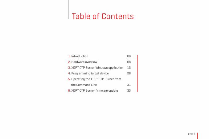
Table of Contents
1. Introduction 06
2. Hardware overview 08
3. XDP™ OTP Burner Windows application 13
4. Programming target device 28
5. Operating the XDP™ OTP Burner from
the Command Line 31
6. XDP™ OTP Burner firmware update 33

page 6
1. Introduction Supported devices
The XDP™ OTP Burner is a specialized tool for programming Infineon’s XDP™ Switching Mode Power Supply ICs (SMPS). This device is designed for two types of users: experts (engineers who conduct the initial configuration) and operators (production line employees who carry out the programming). Having four separate channels, the XDP™ OTP Burner can be used to program up to four SMPS ICs at once (enabling a single production line employee to program a large volume of target devices efficiently).
Infineon’s line of XDP™ Switching Mode Power Supply ICs represent the first all-in-one package solution that integrate a digital power controller with key peripherals. They enable higher energy efficiency, shorter development cycles, lower cost, and more flexibility. For more
information, see the page about XDP™ on
www.infineon.com/cms/en/product/promopages/digital-power
The XDP™ OTP Burner is able to program the following Target devices:
∫ DP2A-based: ICL8105, XDPL8105, IDP2105∫ DP2B-based: XDPL8220
The primary function of the XDP™ OTP Burner is to program target devices. In order to do so, it first needs to be configured by an expert user. The configuration consists of storing data, necessary for programming applied target device, to XDP™ OTP Burner’s internal memory (or, alternatively, onto an external MicroSD Card). This initial setup is performed through a Windows application or alternatively, from the Windows Command Line, using a separate application. After the setup, operators can use the XDP™ OTP Burner as a standalone device or together with the Windows application (or Command Line).
Operating principle
page 7
It’s important to note that the firmware on the target
device can be updated only once (OTP stands for One-
Time-Programmable). The full set of parameters can be
updated up to three times (device dependant).
MikroElektronika provides up to two hours (per purchased
device) of free technical support for the XDP™ OTP Burner
via Skype. This support relates chiefly to questions on how
to integrate the device into a production line.
Customer support
One-time programmable
The Windows application also features an option to generate log files which can be used to document the programming process.

page 8
USB port
9V power jack
MicroSD card slot
Signal LEDs
Ports for communicating
with target ICs (Channel 1, 2,
3 and 4)
Push buttons
2. Hardware overviewOnce configured, the XDP™ OTP Burner is a simple-to-use device whose user interface consists of the following:
∫ Two pushbuttons
∫ Seven signal LEDs
∫ Ports for communicating with target devices (Channel 1, 2, 3 and 4)
∫ USB port for connecting to a PC
∫ 9V DC power jack
∫ MicroSD card slot
page 9
USB port
9V power jack
MicroSD card slot
Signal LEDs
Ports for communicating
with target ICs (Channel 1, 2,
3 and 4)
Push buttons
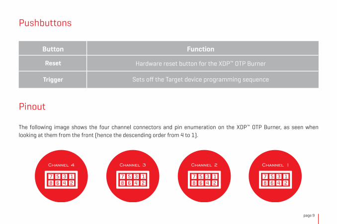
Pushbuttons
Pinout
Button Function
Reset Hardware reset button for the XDP™ OTP Burner
Sets off the Target device programming sequenceTrigger
The following image shows the four channel connectors and pin enumeration on the XDP™ OTP Burner, as seen when looking at them from the front (hence the descending order from 4 to 1).
page 10
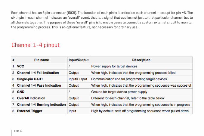
Channel 1-4 pinout
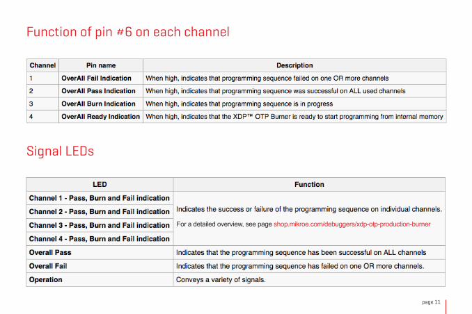
Each channel has an 8 pin connector (IDC8). The function of each pin is identical on each channel — except for pin #6. The sixth pin in each channel indicates an “overall” event, that is, a signal that applies not just to that particular channel, but to all channels together. The purpose of these “overall” pins is to enable users to connect a custom external circuit to monitor the programming process. This is an optional feature, not necessary for ordinary use.
page 11
Function of pin #6 on each channel
Signal LEDs
For a detailed overview, see page shop.mikroe.com/debuggers/xdp-otp-production-burner

page 12
Technical specifications
∫ USB Supply (safe side1): 5V max. 400mA
∫ DC Jack Supply (safe side1): 9V max. 800mA
∫ Safe and galvanic isolation from XDP OTP Burner board to low voltage side (USB and 9V DC Power Jack)
∫ Isolation Voltage 5000Vrms for 1 Min
∫ Maximum voltage swing output (unsafe side2) - Target 5 – 26V
∫ Operating voltage (unsafe side2) - Target 7.5V(typ.)
∫ Tolerance for Vout @7.5V ± 50mV
∫ Maximum ambiance temperature 40ºC
1 Safe side – Safe side of galvanic isolation from XDP board to low voltage side (USB)2 Unsafe side – Unsafe side of galvanic isolation from XDP board to programming connectors.

page 13
3. XDP™ OTP Burner Windows application
The XDP™ OTP Burner Windows application is necessary for preparing configuration that will be used to program target devices.shop.mikroe.com/debuggers/xdp-otp-production-burner
IMPORTANT NOTE: It is mandatory to pair Windows application version with appropriate XDP™ OTP Burner firmware (available on MikroE’s website). Any mismatch between application/firmware versions could cause compatibility issues and malfunctioning. Check the firmware section for instructions.
The XDP™ OTP Burner Windows application is used to make configuration setup, configure XDP™ OTP Burner device, program and monitor programing process of the Infineon SMPS devices.
To properly use the software, the XDP™ OTP Burner must be present and properly connected to a PC at all times. Users will have to connect the target devices to the XDP™ OTP Burner, and then connect the Burner to the PC with a USB cable. If more than one target device is connected, the OTP Burner device must be powered by an external (supplied with the product) 9V/2A power supply (supplied with the product). IDC8 cables and mechanical setup for connecting target devices to the Burner are NOT supplied in the packaging.
Additionally, while making a new configurations setup, one target device must be connected to programmer’s Channel 1 port.
Download Windows application overview
page 14
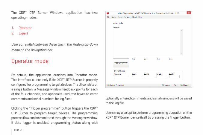
Operator mode
By default, the application launches into Operator mode. This interface is used only if the XDP™ OTP Burner is properly configured for programming target devices. The UI consists of a single button, a Message window, feedback points for each of the four channels, and optionally used text boxes to enter comments and serial numbers for log files.
Clicking the “Trigger programmer” button triggers the XDP™ OTP Burner to program target devices. The programming process flow can be monitored through the Messages window. If data logger is enabled, programming status along with
The XDP™ OTP Burner Windows application has two operating modes:
1. Operator
2. Expert
User can switch between these two in the Mode drop-down
menu on the navigation bar.
optionally entered comments and serial numbers will be saved to the log file.
Users may also opt to perform programming operation on the XDP™ OTP Burner device itself by pressing the Trigger button.
page 15
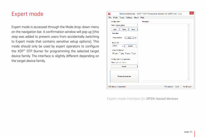
Expert mode
Expert mode interface for DP2A-based devices
Expert mode is accessed through the Mode drop-down menu on the navigation bar. A confirmation window will pop up (this step was added to prevent users from accidentally switching to Expert mode that contains sensitive setup options). This mode should only be used by expert operators to configure the XDP™ OTP Burner for programming the selected target device family. The interface is slightly different depending on the target device family.

page 16
By default, the expert mode brings up the interface for burning DP2B-based devices. To select a different target device family, use the Target drop-down menu on the navigation bar.
A single XDP™ OTP Burner configuration contains a
In either case, in Expert mode, users can:
∫ Prepare and examine configuration setup
∫ Check compatibility with target devices
∫ Configure XDP™ OTP Burner device
∫ Burn target devices and monitor the process
Expert mode interface for DP2B-based device
combination of firmware, patch and parameter data, as well as settings that guide the actual programming process (channel selection, baud rate, IDs comparison algorithm).
The available configuration options are different depending on the selected device family (DP2B-based or DP2A-based). The table below shows the differences.

page 17
Configuration setup for DP2B-based devices
In order to successfully set up a new configuration, Parameter, Patch and Firmware data must have “Before burn” ID values compatible with the target device. The IDs
that are required to match will have corresponding check box ticked in the upper right pane of the table interface. The table will also list “After burn” IDs for reference.
To make sure the ID values are properly compared, it is mandatory that users read ID values from target device as a first step (“Read Channel 1 IDs” button in the centre of the Interface).
The next step is to load Firmware, parameter, Patch (all or only needed) data from individual files. An configuration setup can contain either of the following individual updates or combinations:
∫ Firmware update
∫ Parameter update (which can be either partial or full)
∫ Patch
∫ Firmware and parameter update
∫ Parameter update and patch
The desired update combination is made by ticking checkboxes in the “Data Files” pane:

page 18
Once data files are loaded, the “Before burn” and “After burn” columns will be updated with appropriate values.
It’s also possible to manually input values for Device, FW, Customer and ROM IDs in the “Before burn” column and those values will be used for comparison.
Note the XXXX parameter value in the Before burn column [1 on left image]. This indicates that the config file includes a full set parameter update, making the Before burn parameter value irrelevant. The Before burn parameter ID
See image below and compare the values in the table with the image on the left:
1

page 19
is only important for partial parameter updates.
Optional ID values: Apart from the necessary FW, Patch, and Param values, the ID table contains few optional IDs (Device, Customer, ROM). To include these IDs into the list (for comparison purposes), users need to tick coresponding checkboxes in the Com column.
The procedure for preparing configuration setup for DP2A-based devices is simpler as it allows loading or updating only a full set of parameters. There is also no “Before burn” and “After burn” reference table. Expert users are expected to make sure beforehand that parameter files are adequate for the selected target devices.
Configuration setup for DP2A-based devices
Except described above, the rest of the procedure is the same for both types of target devices.
page 20
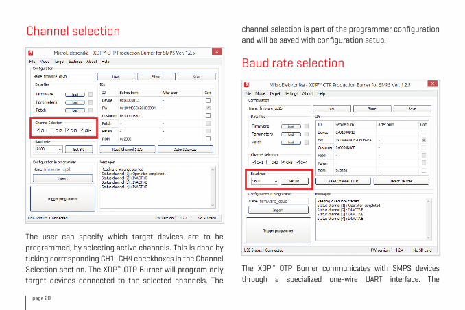
Channel selection
The user can specify which target devices are to be programmed, by selecting active channels. This is done by ticking corresponding CH1-CH4 checkboxes in the Channel Selection section. The XDP™ OTP Burner will program only target devices connected to the selected channels. The
The XDP™ OTP Burner communicates with SMPS devices through a specialized one-wire UART interface. The
Baud rate selection
channel selection is part of the programmer configuration and will be saved with configuration setup.

page 21
communication speed is determined by selected baud rate parameter value. Higher baud rate value shortens the time it takes to complete the communication/operation sequence, but it also makes the communication more sensitive to external interference (noise from surrounding cables, for example). These settings are used during operations of programming, reading IDs or detecting connected target devices.
Baud rate settings are part of XDP™ OTP Burner configuration and will be saved with the configuration setup.
Additionally, the baud rate can be updated at any time by selecting the appropriate value from the drop down list and clicking the “Set BR” button to store the value to the XDP™ OTP Burner.
It is important to understand that, with the option above, the baud rate can be changed at any time without storing the whole configuration to the XDP™ OTP Burner.
This means that current baud rate settings can be different than settings saved as part of the configuration setup.Read Channel 1 IDs and Detect Devices operations are always using current baud rate settings.
Handling the configuration setup: Load, Import, Save and Store Operations
To make a new configuration setup, users can fill in all
configuration fields, or load an existing configuration
setup and only change selected values in the Configuration
section.
An existing configuration setup can be loaded in the Windows application by clicking the Load (1) or Import (4) buttons. The Load operation enables the user to open an existing configuration setup from a file with “.cfg” extension, while the Import operation reads the configuration setup currently stored in the XDP™ OTP Burner device. In both cases, application fields in the Configuration section will be filled with corresponding values fetched. Once loaded/imported, the configuration setup can optionally be modified.
Target device programming operation is always using the baud rate setting saved as part of the configuration setup.

page 22
With all configuration values set, the configuration setup can be saved to a file by clicking the Save (3) button.
In order to properly configure the XDP™ OTP Burner, the selected configuration setup must be stored to XDP™ OTP Burner device by clicking the Store (2) button. Only after a successful execution of this operation, the XDP™ OTP
Burner device will be ready to program target devices. Optionally, to finally verify the stored configuration, users can execute the Import operation and check the loaded configuration values.
NOTE: The Name field in the Configuration pane indicates the name of the currently loaded or new configuration
31 2
4

page 23
Read Channel 1 IDs and Detect Devices Operations
Both operations fetch the full target device ID set with the
following difference.
Detect Devices operation will read the ID values from all 4
channels and display them in a separate (pop-up) window.
This is commonly used to identify connected target
devices, determine if the connected target devices have
expected IDs before programming, or to verify ID values
after programming.
Read Channel 1 IDs operation will read only ID values from
the target device connected to channel 1. This operation
is always performed as a first step when preparing new
configuration setup.
setup, while the same field in the “Configuration in Programmer” sections indicates the name of the configuration currently stored in the XDP™ OTP Burner device. These two fields do not need to match necessarily, except in two cases: (1) if the Import operation is used to load the configuration setup; or (2) if the user wants to save/store the new configuration setup using the same name as the one already stored. Although recommended to be part of, configuration name does not necessarily correspond to configuration (“.cfg”) file name.

page 24
The XDP™ OTP Burner Windows application has a data logger feature. When enabled, all data logs are saved to file(s) in CSV format (CSV file), viewable
from any standard spreadsheet program such as Excel or Google Sheets. The logged data is slightly different depending on the target device family.
The following table lists and describes all data fields of a log entry and their availability within specific target device families:
Logging the programming sequence

page 25
Here is a preview of a log file sample, viewed in Excel:
page 26
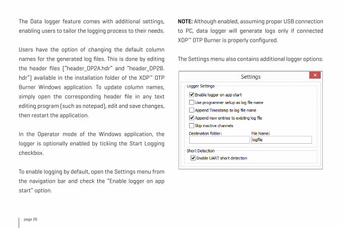
The Data logger feature comes with additional settings,
enabling users to tailor the logging process to their needs.
Users have the option of changing the default column
names for the generated log files. This is done by editing
the header files (“header_DP2A.hdr” and “header_DP2B.
hdr”) available in the installation folder of the XDP™ OTP
Burner Windows application. To update column names,
simply open the corresponding header file in any text
editing program (such as notepad), edit and save changes,
then restart the application.
In the Operator mode of the Windows application, the
logger is optionally enabled by ticking the Start Logging
checkbox.
To enable logging by default, open the Settings menu from
the navigation bar and check the “Enable logger on app
start” option.
NOTE: Although enabled, assuming proper USB connection
to PC, data logger will generate logs only if connected
XDP™ OTP Burner is properly configured.
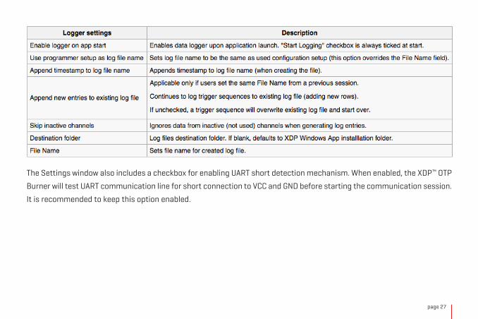
The Settings menu also contains additional logger options:
page 27
The Settings window also includes a checkbox for enabling UART short detection mechanism. When enabled, the XDP™ OTP
Burner will test UART communication line for short connection to VCC and GND before starting the communication session.
It is recommended to keep this option enabled.
page 28
4. Programming target devicesOnce the XDP™ OTP Burner is properly configured, the target devices are programmed either by:
∫ Clicking the “Trigger programmer” button in the XDP™ OTP Burner Windows application’s Expert or Operator mode
∫ Pressing the trigger button on the XDP™ OTP Burner device
Standalone mode
For programming SMPS devices, XDP™ OTP Burner can be used without the Windows application, in Standalone mode. In
this mode, target devices can only be programmed by pressing the trigger button on the XDP™ OTP Burner device. With
Windows application not being used, programming status is displayed on the XDP™ OTP Burner device signal LEDs. Thus,
users need to understand the behavior of signal LEDs and the feedback messages they convey.
page 29
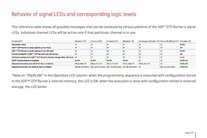
Behavior of signal LEDs and corresponding logic levels
This reference table shows all possible messages that can be conveyed by various patterns of the XDP™ OTP Burner’s signal
LEDs. Individual channel LEDs will be active only if that particular channel is in use.
*Note on “ON/BLINK” in the Operation LED column: when the programming sequence is executed with configuration stored
in the XDP™ OTP Burner’s internal memory, the LED is ON; when the execution is done with configuration stored in external
storage, the LED blinks.

page 30
Using the XDP™ OTP Burner’s external storage (MicroSD)
The programming sequence can also be executed with
configuration stored in the external MicroSD card.
MicroSD card must be formatted with FAT32 file system.
To load the configuration setup to an microSD card, simply
copy the configuration (“.cfg”) file to previously formatted
card — just a single file, without additional files or folders.
Single configuration file must be located in the root folder
of the microSD card.
Whenever a properly formatted MicroSD card with a valid
configuration file is inserted into the slot, it will take
precedence over the configuration stored inside the XDP™
OTP Burner’s internal memory. Thus, target devices will be
programmed with the configuration stored on the MicroSD
card.
page 31
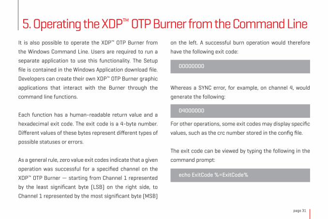
on the left. A successful burn operation would therefore
have the following exit code:
Whereas a SYNC error, for example, on channel 4, would
generate the following:
For other operations, some exit codes may display specific
values, such as the crc number stored in the config file.
The exit code can be viewed by typing the following in the
command prompt:
It is also possible to operate the XDP™ OTP Burner from
the Windows Command Line. Users are required to run a
separate application to use this functionality. The Setup
file is contained in the Windows Application download file.
Developers can create their own XDP™ OTP Burner graphic
applications that interact with the Burner through the
command line functions.
Each function has a human-readable return value and a
hexadecimal exit code. The exit code is a 4-byte number.
Different values of these bytes represent different types of
possible statuses or errors.
As a general rule, zero value exit codes indicate that a given
operation was successful for a specified channel on the
XDP™ OTP Burner — starting from Channel 1 represented
by the least significant byte (LSB) on the right side, to
Channel 1 represented by the most significant byte (MSB)
5. Operating the XDP™ OTP Burner from the Command Line
00000000
04000000
echo ExitCode %=ExitCode%
page 32
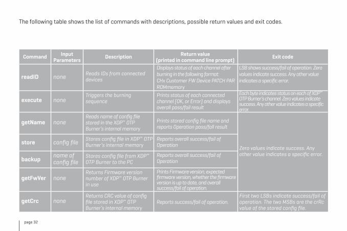
The following table shows the list of commands with descriptions, possible return values and exit codes.
Command InputParameters
Description Return value(printed in command line prompt)
Exit code
readID none
none
none
config file
name of config file
none
none
Reads IDs from connected devices
Triggers the burning sequence
Stores config file in XDP™ OTP Burner’s internal memory
Stores config file from XDP™ OTP Burner to the PC
Returns Firmware version number of XDP™ OTP Burner in use
Returns CRC value of config file stored in XDP™ OTP Burner’s internal memory
Reads name of config file stored in the XDP™ OTP Burner’s internal memory
Prints status of each connected channel (OK, or Error) and displays overall pass/fail result
Prints Firmware version, expected firmware version, whether the firmware version is up to date, and overall success/fail of operation.
Prints stored config file name and reports Operation pass/fall result
Reports overall success/fail of Operation
Reports overall success/fail of Operation
Reports success/fail of operation.
Displays status of each channel after burning in the following format: CHx Customer FW Device PATCH PAR ROMmemory
LSB shows success/fail of operation. Zero values indicate success. Any other value indicates a specific error.
Each byte indicates status on each of XDP™ OTP Burner’s channel. Zero values indicate success. Any other value indicates a specific error.
execute
getName
store
backup
getFwVer
getCrc
Zero values indicate success. Any other value indicates a specific error.
First two LSBs indicate success/fail of operation. The two MSBs are the crRc value of the stored config file.

page 33
6. XDP™ OTP Burner firmware update
The XDP™ OTP Burner comes pre-programmed with
MikroElektronika’s USB-HID Bootloader. This feature
enables firmware updates over the USB. A Windows
application called mikroBootloader is required to complete
the process. For instructions on how to change the
firmware using the mikroBootloader app, refer to
docs.mikroe.com/mikrobootloader
The currently installed firmware version of the XDP™ OTP
Burner device can be read by connecting the device to the
PC, and launching the Windows application. The firmware
version is listed in the bottom right corner of the user
interface. Alternatively, the firmware version can b e r ead
from the Command line by using the “GetFwVer” command.
The firmware updates are available upon request
www.mikroe.com/visitor_contacts*Refers to the firmware for the XDP™ OTP Burner itself, not to be
confused with the firmware for target devices mentioned earlier.


page 35
Important Safety Instructions and Legal NotesPlease read and understand the user manual and the following safety warnings. The direct connection of the open and unprotected board to a power supply poses a severe risk of electric shock. Extra caution must be exercised when handling the exposed conductor, terminals of components or charged capacitors (even after disconnection) as high voltages may present there or at other points across the board.
The XDP™ OTP programmer may only be handled in an electromagnetically controlled environment without significant sources of noise or radio frequency fields, and by persons with sufficient electrical engineering training and experience wearing suitable personal protective equipment such as eye protection. The customer assumes all responsibility and liability for its correct handling and/or use of the XDP™ OTP programmer and undertakes to indemnify and hold MikroElektronika harmless from any third party claim in connection with or arising out of the use and/or handling of the board by the customer.
Every prepared setup needs to be evaluated and the results need to be documented by the user before using this setup. In case of malfunctions, it is necessary to supply device setup and results along with RMA.
The final setup needs to be tested according to all relevant normative requirements.
This means that the following actions are mandatory:1. Every combination of parameter sets/configurations needs to be fully evaluated by a technical expert. Make sure that the combination of parameters used matches your application’s
needs. It is the customer’s responsibility to make sure that the chosen parameters meet all requirements, including safety-related requirements.2. Before using a parameter set, make sure that the system –including any programming/ OTP burning hardware – is fully tested and working as expected.3. Every parameter set is only valid for the dedicated evaluated hardware configuration, including PCB, Layout, used topology and all used electronic components (e.g. MOSFET, Transformer, ...)4. This product must be used with external 9V DC power supply which came in original package with XDP™ OTP Production Burner for SMPS.5. All 4 channels should be connected or covered (if not used) in order to avoid accidental interference from the external environment.
Specifications written in this Document are believed to be accurate but are not guaranteed to be entirely free of error. The information in this Document is subject to change for functional or performance improvements without notice. Please make sure you are reading the latest edition which is always hosted on docs.mikroe.com. While the information herein is assumed to be accurate, MikroElektronika assumes no responsibility for any errors or omissions. MikroElektronika makes and you receive no warranties or conditions, express, implied or statutory. MikroElektronika specifically disclaims any implied warranty of merchantability or fitness for a particular purpose.
Note: the certification for isolation requirements is only valid for the XDP™ OTP Production Burner for SMPS (without application cable and application connector).Note: The user has to cover the whole application board including the cable and connector with a housing fulfilling isolation Class II requirements.Note: At some frequencies of Radiated RF emissions (130-188MHz range) degradation of performance could occur in terms of loss of connection with personal computer or laptop or delays in software execution. In this case, the XDP™ OTP Production Burner should be removed from the source of disturbances.Note: At some frequencies of Conducted RF emissions (10-30MHz range) degradation of performance could occur in terms of loss of connection with PC/Laptop or delays in software execution. In this case device should be reset with pressing the reset button. In case that issues occur frequently XDP™ OTP Production Burner should be removed from the source of disturbances.

page 36
Designed by
MikroElektronika Ltd.
www.mikroe.com
If you want to learn more about our products, please visit our website at www.mikroe.comIf you are experiencing some problems with any of our products or just need additional information, please place your ticket at www.helpdesk.mikroe.comIf you have any questions, comments or business proposals, do not hesitate to contact us at [email protected]
XDP™ OTP Production Burner for SMPS
XDP™ OTP Production Burnerfor SMPS - Manual
3500000138538