Embed Size (px)
Citation preview

This document is controlled by the originating SCE T&D organization. When downloaded and printed,
this document becomes UNCONTROLLED, and users should check with the originator to ensure that
they have the latest version. This applies to the remainder of the document

This document is controlled by the originating SCE T&D organization. When downloaded and printed,
this document becomes UNCONTROLLED, and users should check with the originator to ensure that
they have the latest version. This applies to the remainder of the document
Transmission & Distribution Electric System Planning
Document No. 1
Version No. 9
INTERCONNECTION HANDBOOK Effective Date 12/13/2018
Approved by:
Original Signed by
12/13/2018
Garry Chinn, Senior Engineering Manager Electric System Planning Date
Transmission & Distribution Electric System Planning
Document No. 1
Version No. 9
INTERCONNECTION HANDBOOK Effective Date 12/13/2018
P a g e i
CONTENTS
Introduction and Summary of Technical Requirements ....................................................................... 1
Introduction ......................................................................................................................................... 1
1.1.1 Purpose of Interconnection Handbook ................................................................................................. 1
1.1.2 Conformity ............................................................................................................................................ 3
1.1.3 Requirements are Subject to Change .................................................................................................... 3
1.1.4 Applicability ........................................................................................................................................... 3

Transmission & Distribution Electric System Planning
Document No. 1
Version No. 9
INTERCONNECTION HANDBOOK Effective Date 12/13/2018
P a g e 1
INTRODUCTION AND SUMMARY OF TECHNICAL REQUIREMENTS
Southern California Edison Company’s (SCE) Interconnection Handbook (Handbook) is broken up into
three distinct parts based on the customer project type that are being connected, planned to be connected,
or facility additions and modifications to existing customer facilities interconnected to the SCE's electric
system.
The three parts of the handbook address:
Generator Interconnections;
Transmission Interconnections, and
End-User Facility Interconnections
Collectively these types of interconnections are referred to in the Handbook as “Interconnected Facility
(INTFAC).”
There is a fourth section in the Interconnection Handbook that addresses how SCE will work towards a
solution to mitigate any adverse impact on affected systems using the CAISO tariff.
The Handbook specifies what is necessary for facilities to interconnect to SCE's electric system
(Requirements), or locations where SCE is the operating agent, which shall be referred to as “SCE’s
electric system”. These Requirements provide for safe and reliable operation of SCE's electric system.
As a Transmission Owner (TO), SCE is required to provide and maintain a Handbook to guide entities
that need to interconnect to SCE’s electric system. Please note that generators directly connecting to SCE
transmission facilities must also adhere to the California Independent System Operator’s generation
interconnection procedures. This is because these facilities are under CASIO operational control and they
perform the Transmission Operator (TOP) function for them.
Link to CAISO Fifth Replacement FERC Electric Tariff:
http://www.caiso.com/rules/Pages/Regulatory/Default.aspx
Introduction
1.1.1 Purpose of Interconnection Handbook The Handbook was written to provide SCE’s customers an overview of the Requirements to
address interconnection requests, and to support compliance with NERC Reliability Standard,
FAC-001-3, and Facility Connection Requirements. It also provides a means to facilitate
communication of technical information to SCE regarding the INTFAC, and are not meant to be
used as a design specification for the INTFAC.
SCE’s Requirements do not cover all aspects of the necessary technical criteria applicable to an
INTFAC project, and the final design of facility connections to the SCE’s electric system will be
subject to SCE review and approval on a case-by-case basis.
Transmission & Distribution Electric System Planning
Document No. 1
Version No. 9
INTERCONNECTION HANDBOOK Effective Date 12/13/2018
P a g e 2
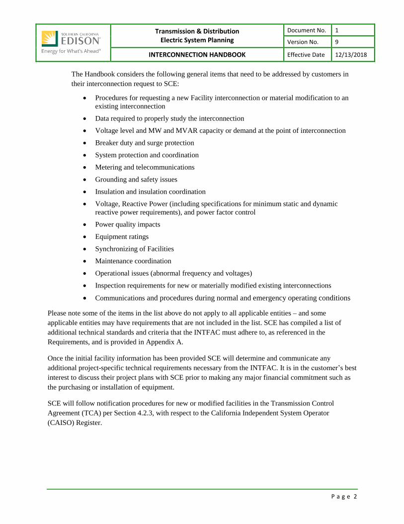
The Handbook considers the following general items that need to be addressed by customers in
their interconnection request to SCE:
Procedures for requesting a new Facility interconnection or material modification to an
existing interconnection
Data required to properly study the interconnection
Voltage level and MW and MVAR capacity or demand at the point of interconnection
Breaker duty and surge protection
System protection and coordination
Metering and telecommunications
Grounding and safety issues
Insulation and insulation coordination
Voltage, Reactive Power (including specifications for minimum static and dynamic
reactive power requirements), and power factor control
Power quality impacts
Equipment ratings
Synchronizing of Facilities
Maintenance coordination
Operational issues (abnormal frequency and voltages)
Inspection requirements for new or materially modified existing interconnections
Communications and procedures during normal and emergency operating conditions
Please note some of the items in the list above do not apply to all applicable entities – and some
applicable entities may have requirements that are not included in the list. SCE has compiled a list of
additional technical standards and criteria that the INTFAC must adhere to, as referenced in the
Requirements, and is provided in Appendix A.
Once the initial facility information has been provided SCE will determine and communicate any
additional project-specific technical requirements necessary from the INTFAC. It is in the customer’s best
interest to discuss their project plans with SCE prior to making any major financial commitment such as
the purchasing or installation of equipment.
SCE will follow notification procedures for new or modified facilities in the Transmission Control
Agreement (TCA) per Section 4.2.3, with respect to the California Independent System Operator
(CAISO) Register.

Transmission & Distribution Electric System Planning
Document No. 1
Version No. 9
INTERCONNECTION HANDBOOK Effective Date 12/13/2018
P a g e 3
In addition, customers may also inquire about SCE’s interconnection procedures and for notification of
new or modified generation, transmission, and end-user facilities from the following contact:
Contact Mailing Address
Manager, Grid Interconnection & Contract Development
P.O. Box 800
2244 Walnut Grove Avenue
Rosemead, California 91770
1.1.2 Conformity The INTFAC shall comply with all applicable NERC Reliability Standards, WECC Reliability
Criteria and Guidelines, along with any WECC, SCE and CAISO system planning and
performance guidelines for its facilities. SCE will not assume any responsibility for complying
with mandatory reliability standards for such facilities and offers no opinion whether the
Interconnection Customer must register with NERC pursuant to Section 215 of the Federal Power
Act. If required to register with NERC, the INTFAC shall be responsible for complying with all
Applicable Reliability Standards for its facilities.
The INTFAC is responsible for conforming to applicable:
Federal Energy Regulatory Commission (FERC) Rules, Regulations, and Orders
North American Electric Reliability Corporation (NERC) Standards
Western Electricity Coordinating Council (WECC) Regional Criteria, Policies, and
Guidelines
California Independent System Operator (CAISO) Planning Standards
SCE Reliability Criteria, as well as good engineering and utility practice.
1.1.3 Requirements are Subject to Change These Requirements are subject to change. INTFACs have the responsibility to ensure that they
comply with the most recent version of the Interconnection Requirements. The current version
may be accessed at SCE's internet site, https://www.sce.com/. Each page of the Handbook
displays its effective date in the upper right hand corner.
1.1.4 Applicability Upon execution of an Interconnection Agreement per the appropriate tariff, the INTFAC should
make reference to this document in its entirety during the construction process.

Transmission & Distribution Electric System Planning
Document No. 1
Version No. 9
INTERCONNECTION HANDBOOK Effective Date 12/13/2018
This document is controlled by the originating SCE T&D organization. When downloaded and printed, this document becomes UNCONTROLLED,
and users should check with the originator to ensure that they have the latest version. This applies to the remainder of the document.
Transmission & Distribution Electric System Planning
Document No. 1
Version No. 9
INTERCONNECTION HANDBOOK Effective Date 12/13/2018
P a g e i
CONTENTS
Section 1 Generator Interconnection Overview ............................................................................... 1
Section 2 Parallel Systems ............................................................................................................... 2
Parallel Operation ................................................................................................................................ 2
Need for Protective Devices ................................................................................................................ 2
Hazards ................................................................................................................................................ 2
Islanding ............................................................................................................................................... 3
UPS ....................................................................................................................................................... 3
Section 3 Protection Requirements ................................................................................................. 4
Category 1: Voltage Over 34.5 kV ....................................................................................................... 5
3.1.1 Specific Requirements for Category 1 ................................................................................................... 9
3.1.2 Protective relays which perform the following functions ..................................................................... 9
Category 2: Total Generation 200 kVA and Above, Voltage at 34.5 kV or Below ............................. 11
3.2.1 The Producer shall provide adequate protective devices ................................................................... 14
3.2.2 Protection devices which may be required to satisfy the above Requirements ................................. 15
3.2.3 Other protection devices for Category 2 Generation .......................................................................... 16
3.2.4 Exemption For Installing Phase Over-current Protective Devices ....................................................... 16
Category 3: Total Generation Less Than 200 kVA, in Voltage at 34.5kV & Below ............................. 17
Breaker Duty and Surge Protection ................................................................................................... 21
3.4.1 SCE Duty Analysis ................................................................................................................................ 21
3.4.2 Customer Owned Duty/Surge Protection Equipment ......................................................................... 22
Underfrequency Relays ...................................................................................................................... 22
Section 4 Miscellaneous Requirements: ........................................................................................ 23
Power System Stabilizers (PSS) .......................................................................................................... 23
Governor “Droop” Shall Be Set At 5% ................................................................................................ 23
Wind Turbine Generating Facilities ................................................................................................... 23
4.3.1 Wind Turbine Set-Back Criteria ........................................................................................................... 23
4.3.2 Generator Electric Grid Fault Ride-Through Capability and Power Factor Criteria ............................. 24
Reclosing Circuit Breakers and Hot Line Reclose Blocking ................................................................ 24
Unbalanced Currents ......................................................................................................................... 25
Sub-Synchronous Interaction Evaluations ......................................................................................... 25
4.6.1 Sub-Synchronous Resonance Studies .................................................................................................. 25
4.6.2 Sub-Synchronous Control Interaction Studies .................................................................................... 25
Voltage Control .................................................................................................................................. 26
Insulation Coordination ..................................................................................................................... 26
Ratings ............................................................................................................................................... 27
4.9.1 Facility Ratings ..................................................................................................................................... 27
4.9.2 Ratings Provided by Equipment Manufacturers ................................................................................. 27
4.9.3 Rating Practice ..................................................................................................................................... 27

Transmission & Distribution Electric System Planning
Document No. 1
Version No. 9
INTERCONNECTION HANDBOOK Effective Date 12/13/2018
P a g e ii
4.9.4 Ambient Conditions ............................................................................................................................. 27
4.9.5 Transmission Lines .............................................................................................................................. 27
4.9.6 Overhead Conductors ......................................................................................................................... 27
4.9.7 Underground Cable ............................................................................................................................. 28
4.9.8 Series and Shunt Compensation Devices ............................................................................................ 28
4.9.9 Terminal Equipment ............................................................................................................................ 28
4.9.10 Transformer Bays ................................................................................................................................ 28
4.9.11 Transformer Normal Ratings ............................................................................................................... 28
4.9.12 Transformer Emergency Ratings ......................................................................................................... 28
4.9.13 Parallel Operation of Transformers ..................................................................................................... 29
4.9.14 Relays Protective Devices .................................................................................................................... 29
4.9.15 Path Ratings ......................................................................................................................................... 29
Synchronizing of Facilities .................................................................................................................. 29
Maintenance Coordination and Inspection ....................................................................................... 29
Abnormal Frequency and Voltages .................................................................................................... 30
4.12.1 Joint Reliability Procedures ................................................................................................................. 30
4.12.2 Voltage and Reactive Flows ................................................................................................................. 30
4.12.3 Transfer Limits Under Outage and Abnormal System Conditions ....................................................... 30
Communications and Procedures ...................................................................................................... 30
4.13.1 Use of Communication System ........................................................................................................... 30
4.13.2 Remedial Action Schemes Communication Equipment Requirements .............................................. 30
4.13.3 Critical System Voltage Operation ...................................................................................................... 30
Section 5 General Operating Requirements: .................................................................................. 31
Generating Facility Records and Data ................................................................................................ 32
SCE ..................................................................................................................................................... 32
Operating Data and Records the Producer Must Provide SCE Upon Request .................................. 34
Calibration of Producer Owned Protective Apparatus ...................................................................... 34
Disconnecting Service to a Generation Facility ................................................................................. 35
Voltage Variations .............................................................................................................................. 35
VAR Correction ................................................................................................................................... 36
5.7.1 Interconnection ................................................................................................................................... 36
5.7.2 Subtransmission System ...................................................................................................................... 36
Voltage Regulation/Reactive Power Supply Requirements ............................................................... 37
5.8.1 Reactive Power Equipment – Induction Generators (in aggregate) .................................................... 37
5.8.2 Reactive Power Supply Requirements - Synchronous Generators ...................................................... 38
5.8.3 Reactive Power Supply Requirements - Inverter Systems .................................................................. 39
5.8.4 Voltage and Reactive Control .............................................................................................................. 39
Ride Through Requirements .............................................................................................................. 39
Off Nominal Frequency and Voltage Ride Through ........................................................................... 39
Off Nominal Frequency ...................................................................................................................... 40
5.11.1 Category 1 ........................................................................................................................................... 40
Transmission & Distribution Electric System Planning
Document No. 1
Version No. 9
INTERCONNECTION HANDBOOK Effective Date 12/13/2018
P a g e iii
5.11.2 Category 2 ........................................................................................................................................... 40
5.11.3 Category 3 ........................................................................................................................................... 40
Voltage Ride-Through ........................................................................................................................ 40
5.12.1 Category 1 ........................................................................................................................................... 40
5.12.2 Category 2 ........................................................................................................................................... 40
5.12.3 Category 3 ........................................................................................................................................... 40
5.12.4 Inverter-Based Category 2 and 3 ......................................................................................................... 41
Voltage Imbalance and Abnormal Voltage or Current Waveforms (harmonics)............................... 41
5.13.1 Voltage Imbalance ............................................................................................................................... 41
5.13.2 Harmonics ........................................................................................................................................... 42
5.13.3 Disconnection ...................................................................................................................................... 42
5.13.4 Photovoltaic Inverter Systems ............................................................................................................ 42
Isolating Equipment Requirements and Switching & Tagging Rules ................................................. 42
5.14.1 Applicable to Generation Facilities connecting to voltages > 34.5KV ................................................. 42
5.14.2 Applicable to Generation Facilities connecting to voltages ≤ 34.5KV ................................................. 43
Grounding Circuits and Substations .................................................................................................. 44
5.15.1 Nominal Voltage and Grounding ......................................................................................................... 44
5.15.2 Grounding Grid Studies shall be conducted in the following situations: ............................................ 45
5.15.3 Ground Mats ....................................................................................................................................... 45
5.15.4 Substation Grounding ......................................................................................................................... 46
Non-SCE Pole Grounding ................................................................................................................... 46
Section 6 Revenue Metering Requirements ................................................................................... 48
General Information .......................................................................................................................... 48
Retail Service ...................................................................................................................................... 48
Revenue Metering Requirements for Generators ............................................................................. 48
6.3.1 General Information ............................................................................................................................ 48
Location/Ownership of CAISO Metering Equipment ......................................................................... 50
Section 7 Telemetering Requirements (Hardware) ......................................................................... 51
Telemetering Requirements .............................................................................................................. 51
Total Generation 1MVA Nameplate or More .................................................................................... 51
7.2.1 The following specifications are to be used as informational guidelines to facilitate the Centralized Telemetry Method installation at the Generation Facility: ................................................................. 51
7.2.2 The following specifications are to be used as informational guidelines to facilitate the RTU installation at the Generation Facility: ................................................................................................ 52
Exemption for Cold-Iron and Emergency-Backup Generators .......................................................... 57
7.3.1 Cold-Ironing is the action of providing shore-side electrical power to a ship at berth while its on-board generator(s) are shut down. ..................................................................................................... 57
7.3.2 Emergency-Backup Generation (EBG) is customer-owned generation utilized when disruption of utility power has occurred or is imminent. ......................................................................................... 57
Section 8 Telecommunications Requirements ................................................................................ 58
General Description ........................................................................................................................... 58

Transmission & Distribution Electric System Planning
Document No. 1
Version No. 9
INTERCONNECTION HANDBOOK Effective Date 12/13/2018
P a g e iv
Fiber Optic Cable and Communications Paths: ................................................................................. 58
Space Requirements .......................................................................................................................... 59
HVAC Requirements .......................................................................................................................... 60
Power And Grounding Requirements ................................................................................................ 60
Telemetry and Leased T1 Line: .......................................................................................................... 61
Miscellaneous: ................................................................................................................................... 61
Section 9 Property Requirements .................................................................................................. 63
Right of Way Requirements ............................................................................................................... 63
Transmission Line Crossing Policy ...................................................................................................... 63
Infrastructure Property Requirements .............................................................................................. 63
Section 10 Generator Sharing Breaker and a Half ............................................................................. 65
Summary ............................................................................................................................................ 65
Section 11 Smart Inverters .............................................................................................................. 66
TABLES
Table 5.1: Typical Communication Requirements Per Generating Facility Size.......................................................... 32 Table 5.2: Typical Required Generating Facility Records and Data ............................................................................ 33 Table 5.3: Required Test Intervals for Protective Devices .......................................................................................... 35 Table 5.4: Electric System Jurisdiction and Tap-setting Specification ........................................................................ 36 Table 5.5: Power Factor Criteria ................................................................................................................................. 37 Table 5.6: Off Nominal Frequency Limits .................................................................................................................... 40 Table 5.7: Generator Frequency and Voltage Protective Relay Settings .................................................................... 41 Table 7a: Telemetry Requirements ............................................................................................................................ 54
FIGURES
Figure 3a: Typical Synchronous Parallel Generation with Assumed SCE Owned Protection (> 34.5 kV) ..................... 6 Figure 3b: Typical Induction Parallel Generation with Assumed SCE Owned Protection (>34.5 kV) ............................ 7 Figure 3c: Typical Parallel Generation Utilizing Inverter Technology Assumed SCE Owned Protection ( >34.5 kV) .... 8 Figure 3d: Typical Synchronous Parallel Generation with Assumed Producer Owned Protection (> 200 kVA, < 34.5
kV) ........................................................................................................................................................... 12 Figure 3e: Typical Induction Parallel Generation with Assumed Producer Owned Protection (> 200 kVA, < 34.5
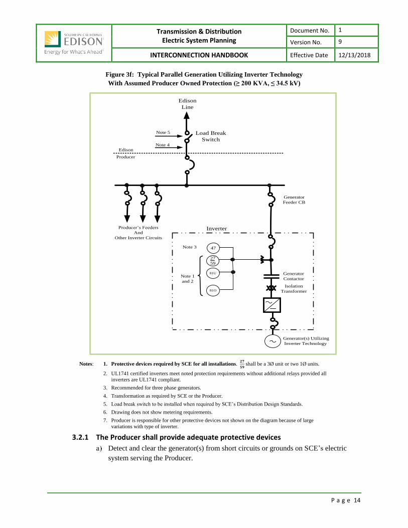
kV) ........................................................................................................................................................... 13 Figure 3f: Typical Parallel Generation Utilizing Inverter Technology With Assumed Producer Owned Protection (≥
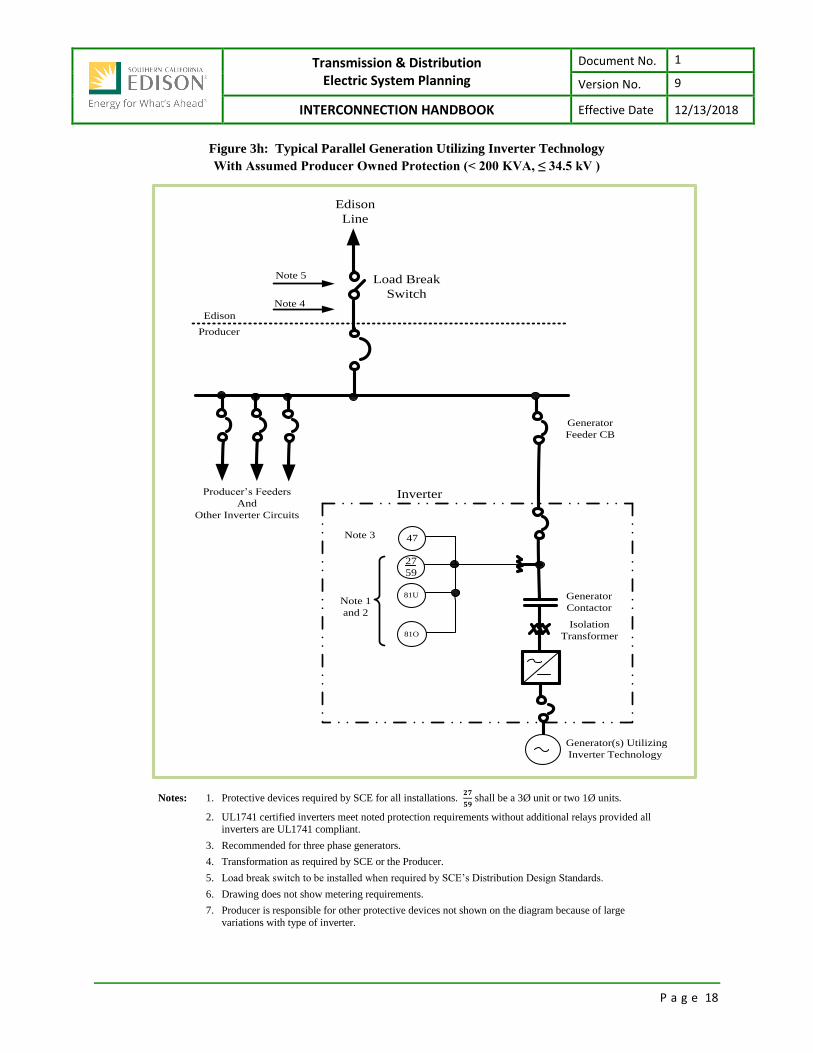
200 KVA, ≤ 34.5 kV) ................................................................................................................................. 14 Figure 3g: Typical Parallel Generation Under 200 kVA ............................................................................................... 17 Figure 3h: Typical Parallel Generation Utilizing Inverter Technology With Assumed Producer Owned Protection (<
200 KVA, ≤ 34.5 kV ) ................................................................................................................................ 18 Figure 3i: Typical Relay/Contactor Arrangement Under 200 kVA .............................................................................. 20 Figure 5a: Typical Isolating Disconnect Device Configuration .................................................................................... 44 Figure 6a: Typical Metering Installation for a Generating Facility .............................................................................. 49 Figure 6b: Location/Ownership of CAISO Metering Equipment for a Generating Facility ......................................... 50

Transmission & Distribution Electric System Planning
Document No. 1
Version No. 9
INTERCONNECTION HANDBOOK Effective Date 12/13/2018
P a g e v
Figure 7a: Typical Remote Terminal Unit (RTU) Installation 1MVA ≤ Total Generation ≤ 10MVA interconnected to
an SCE Substation or Total Generation ≥ 10MVA .................................................................................. 55 Figure 7b: Typical Centralized Telemetry Method (CTM) Installation 1MVA ≤ Total Generation < 10MVA
interconnected to an SCE (34.5 kV or below) Distribution Circuit .......................................................... 56
Transmission & Distribution Electric System Planning
Document No. 1
Version No. 9
INTERCONNECTION HANDBOOK Effective Date 12/13/2018
P a g e 1
SECTION 1 GENERATOR INTERCONNECTION OVERVIEW The Generator Interconnection Section specifies what is necessary for generation facilities to interconnect
to SCE's electric system, and gives customers an overview of the Requirements to address interconnection
requests. It also provides a means to facilitate the communication of technical information to SCE
regarding the generation facilities interconnecting to SCE's electric system.
Throughout this section the term “Producer” shall refer to the owner, its agents, or the operator of
facilities being interconnected to SCE’s electric system that includes performing the functions of
supplying energy and a service (exclusive of basic energy and transmission services) to support the
reliable operation of the transmission system.
All Producers with generation connected to SCE’s electrical system, regardless of voltage or
classification, are required to adhere to SCE’s Generation Modeling Data Requirements.
SCE’s Generation Modeling Requirements can be found at “Link”
Transmission & Distribution Electric System Planning
Document No. 1
Version No. 9
INTERCONNECTION HANDBOOK Effective Date 12/13/2018
P a g e 2
SECTION 2 PARALLEL SYSTEMS These Requirements apply to interconnecting generating facilities that intend to operate in parallel with
SCE’s electric system, and, in some instances, ultimately deliver power to the CAISO grid (directly to the
transmission system, or via SCE’s Distribution system).
Subject to FERC, California Public Utilities Commission (CPUC) regulations, and SCE approval, a
Producer may elect to operate a generator facility in parallel with SCE or as a separate system with the
capability of non-parallel load transfer between the two independent electrical systems. Induction
generators, and some systems using inverter devices, must be operated in parallel to produce energy.
Synchronous generators may be operated either in parallel or as a separate system. However, please note
that the Requirements provided in this document are applicable to interconnecting generators intending to
operate in parallel.
Parallel Operation A parallel operation is one in which the Producer's generating facilities operated connected to SCE’s
electric system. A consequence of such parallel operation is that the parallel generator becomes a part of
SCE’s electric system, and must, therefore, be considered in planning the protection of SCE’s electric
system. To be allowed to operate in parallel with the electric grid, the generating facility must meet the
technical specification as outlined in the relevant section of this document.
Need for Protective Devices Prudent electrical practices require that certain protective devices (relays, circuit breakers, etc.) must be
installed at any location where a Producer desires to operate its generating facilities in parallel with the
SCE system. The purpose of these devices is to isolate faults from the Electrical Grid and promptly
disconnect the Producer's generating equipment from the SCE system when faults or abnormal operation
jeopardize the reliable operation of equipment or the safety of personnel. Other modifications to
electrical system configuration or protective relays may also be required in order to accommodate parallel
generation. SCE assumes no responsibility for determining protective equipment needed to protect
Producer’s facilities.
Hazards SCE’s transmission and distribution lines are subject to a variety of natural and man-made hazards.
Among these are lightning, earthquakes, wind, animals, automobiles, mischief, fire, and human error.
Producer’s electric systems are subject to these same hazards but not nearly to the same degree because
SCE’s electric system has greater exposure to these hazards.
The electric problems that can result from these hazards are principally short circuits, grounded
conductors, and broken conductors. These fault conditions require that damaged equipment be de-
energized as soon as possible to ensure public safety and continued operation of the remainder of SCE’s
electric system.
Where SCE controls the only source of supply to a given transmission or distribution line, it has the sole
responsibility to install protective equipment to detect faulted equipment or other operating abnormalities
and to isolate the problem from the remainder of SCE’s electric system. A non-SCE generating facility

Transmission & Distribution Electric System Planning
Document No. 1
Version No. 9
INTERCONNECTION HANDBOOK Effective Date 12/13/2018
P a g e 3
connected to and operated in parallel with an SCE line represents another source of power to energize the
line. Accordingly, SCE requires that such facilities also have adequate protective devices installed to
react to abnormal electric system conditions and isolate from SCE’s electric system.
Islanding Generating facilities operating in parallel with SCE’s electric system must also be equipped to detect
another condition referred to as "unintentional islanding." Islanding is the abnormal operating condition
where a portion of SCE's electric system and loads become isolated from the remainder of SCE’s electric
system while still connected to and receiving energy from generating facilities within an electrical island.
When unintentional islanding occurs, all generating facilities within the electrical island must be
disconnected to prevent continued operation.
The protective devices and other Requirements identified in Section 3 are intended to provide protection
against hazards, such as those noted above, by ensuring that parallel generating facilities are disconnected
when abnormal operating conditions occur. The following sections reflect the fact that these
Requirements are typically minimal for small installations, but increase in scope and/or complexity as the
size of the generation installation increases. SCE may require voltage and frequency protective functions
or relays to detect islanding and shut down generation during periods of islanding.
UPS Uninterruptible Power Supply (UPS) systems will be classified as either a separate or a parallel system
depending on the following criteria. If such UPS systems are not capable of transfer of electric power
from the emergency source to SCE’s electric system, they will be classified as a separate system
generating facility. If such UPS systems are capable of transfer of power, they must meet the
Requirements for parallel generation.

Transmission & Distribution Electric System Planning
Document No. 1
Version No. 9
INTERCONNECTION HANDBOOK Effective Date 12/13/2018
P a g e 4
SECTION 3 PROTECTION REQUIREMENTS
Protective devices (relays, circuit breakers, synchronizing equipment, etc.) must be installed for the
protection of SCE’s electric system as required by SCE. Generally, the protective devices may differ with
the relative electrical capacity of the installation. The larger the installation, the greater the effect it may
have on SCE’s electric system. For instance, a manual disconnecting device must be provided by the
Producer, but the form of this device will vary with the service voltage and generating facility capacity.
While some protection requirements can be standardized, the detailed protection design highly depends
on the Producer’s generator size, type and characteristics, number of generators, interconnection line
characteristics (i.e., voltage, impedance, and ampacity), as well as the existing protection equipment and
configuration of SCE’s surrounding electric system. Fault duty, existing relay schemes, stability
requirements, and other considerations may impact the selection of protection systems. Consequently,
identical generation facilities connected at different locations in SCE’s electric system can have widely
varying protection requirements and costs. The varying protection requirements will be used to define the
corresponding Telecommunications requirements, (See Section 8.)
For voltage classes 200 kV and above, primary relay protection for network transmission circuits will be
designed to clear transmission line faults within a maximum of 6 cycles. Project stability studies may
indicate that faster clearing times are necessary. To ensure the reliability of the electric system, protective
relays, and associated equipment require periodic maintenance/replacement. Typically the frequency of
transmission line relay replacement does not exceed once every fifteen (15) years, but equipment failure,
availability of replacement parts, system changes, or other factors may alter the relay system replacement
schedule. If equipment does fail, that may impact the reliability of the electric system and it shall be
replaced according to the Interconnection Agreement.
For Generation interconnections utilizing a sub-transmission line interconnection at voltage 66 and 115
kV or transmission line at 220 kV and 500 kV, Producers shall utilize Protection Requirements as defined
in this Interconnection Handbook Part 3 Transmission Interconnection Requirements Section 2.
Categories: SCE’s Requirements identify three different categories for Producer generating facilities
connecting to the SCE electric system each with distinctive protection Requirements. These categories
are:
1. Interconnection voltage above 34.5 kV
2. 200 kVA and above capacity, interconnection voltage 34.5 kV or below
3. Less than 200 kVA capacity, interconnection voltage 34.5 kV or below
Aggregation: Where multiple generating facilities (with a single owner) are allowed to connect to SCE’s
electric system through a single point of interconnection, the interconnection is said to have aggregated
generating facilities. The appropriate category of aggregated generating facilities is calculated by
summing the KVA ratings of the multiple generators.
Disclaimer: The categories above have been established for convenience and are based on
urban/suburban circuits with normal load density. The final decision as to the specific requirements for
Transmission & Distribution Electric System Planning
Document No. 1
Version No. 9
INTERCONNECTION HANDBOOK Effective Date 12/13/2018
P a g e 5
each installation will be made by SCE depending on several factors that could include Producer load
magnitude, the magnitude of other load connected to that circuit/system, available short circuit duty
contribution, and other conditions SCE deems prudent.
The Protection Requirements of the above three categories are described in Sections 3.1 to 3.3. These
sections include Figures 3a through 3i which illustrate typical installations for protection equipment. The
following is a legend of device numbers referred to in these figures:
Legend
Protective Device Numbers and Description
4 Master Contactor
25 Synchronizing or Synchronism Check
27 Under-voltage
32 Power Direction
40 Loss of Field Detection
46 Current Balance
47 Voltage Phase Sequence
50 Breaker Failure
51 Time Over-current
51G Ground Time Over-current
51N Neutral Time Over-current
51V Voltage Restrained/Controlled Time Over-current
59 Over-voltage
59G Over-voltage Type Ground Detector
67V Voltage Restrained/Controlled Directional Time Over-current
78 Loss of Synchronism (Out-of-Step)
79 Reclosing Relay
81O Over-frequency
81U Under-frequency
87 Current Differential
87L Transmission Line Differential
NOTE: For additional information on device numbers, refer to ANSI C37.2.
Category 1: Voltage Over 34.5 kV This Category is limited to generating facilities interconnecting at a single point with interconnection
voltage above 34.5 kV. This requirement applies to all interconnections to the CAISO Controlled Grid,
and to interconnections to SCE owned and operated facilities above 34.5 kV.
Typical Installations
Figures 3a, 3b and 3c show typical installations with the SCE interface.

Transmission & Distribution Electric System Planning
Document No. 1
Version No. 9
INTERCONNECTION HANDBOOK Effective Date 12/13/2018
P a g e 6
Figure 3a: Typical Synchronous Parallel Generation with
Assumed SCE Owned Protection (> 34.5 kV)
Feeders
Edison
Producer
Edison
Line
Syn
Gen
Syn
Gen
Note 3
59G
25
81U
81O
32
78
67V
Note 2
Edison
Producer
Note 2
Note 1
47
79
27
59
5151N
Notes: 1 Producer’s main breaker or switch.
2. Transformation, if required, may be by SCE or the Producer.
3. Relay operates on two different phase-to-phase voltages.
Not all Producer-side protective relaying is shown.

Transmission & Distribution Electric System Planning
Document No. 1
Version No. 9
INTERCONNECTION HANDBOOK Effective Date 12/13/2018
P a g e 7
Figure 3b: Typical Induction Parallel Generation with
Assumed SCE Owned Protection (>34.5 kV)
Feeders
Edison
Producer
Edison
Line
Ind
Gen
Ind
Gen
Note 327
59
59G
47
79
25
81U
81O32
Note 2
Edison
Producer
Note 2
Note 15151N
Note 4Note 4
Notes: 1. Producer’s main breaker or switch.
2. Transformation, if required, may be by SCE or the Producer.
3. Relay operates on two different phase-to-phase voltages.
4. See Section 5.8.
Not all Producer-side protective relaying is shown.
For induction generation interconnection facilities, the Producer is responsible for installing the
appropriate VAR supporting equipment at its facility to maintain unity power factor at the point of
interconnection.
Transmission & Distribution Electric System Planning
Document No. 1
Version No. 9
INTERCONNECTION HANDBOOK Effective Date 12/13/2018
P a g e 8
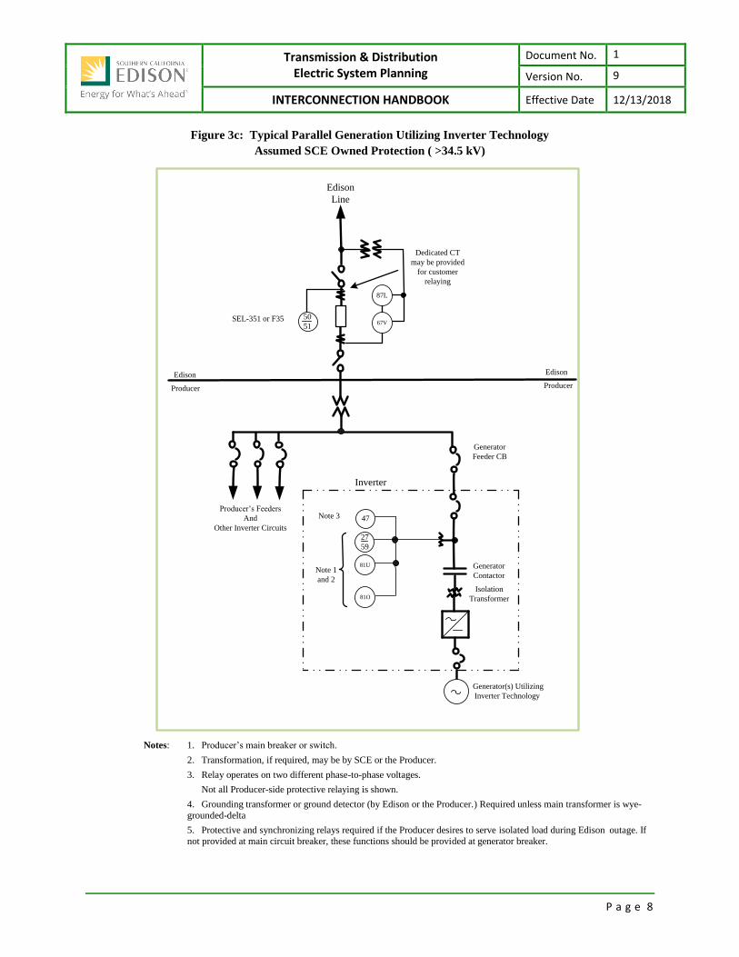
Figure 3c: Typical Parallel Generation Utilizing Inverter Technology
Assumed SCE Owned Protection ( >34.5 kV)
Edison
Producer
Edison
Line
87L
67V
Edison
Producer
Producer’s Feeders
And
Other Inverter Circuits
47
27
59
81U
81O
Note 3
Note 1
and 2
Generator
Contactor
Inverter
Generator
Feeder CB
Generator(s) Utilizing
Inverter Technology
Isolation
Transformer
50
51SEL-351 or F35
Dedicated CT
may be provided
for customer
relaying
Notes: 1. Producer’s main breaker or switch.
2. Transformation, if required, may be by SCE or the Producer.
3. Relay operates on two different phase-to-phase voltages.
Not all Producer-side protective relaying is shown.
4. Grounding transformer or ground detector (by Edison or the Producer.) Required unless main transformer is wye-
grounded-delta
5. Protective and synchronizing relays required if the Producer desires to serve isolated load during Edison outage. If
not provided at main circuit breaker, these functions should be provided at generator breaker.
Transmission & Distribution Electric System Planning
Document No. 1
Version No. 9
INTERCONNECTION HANDBOOK Effective Date 12/13/2018
P a g e 9
3.1.1 Specific Requirements for Category 1
Typically SCE-owned and controlled circuit breaker to isolate generation facilities
during SCE’s electric system disturbances.
Producer-owned and controlled circuit breaker or disconnect switch (as required –
refer to Section 5.14 Isolating Equipment Requirements and Switching & Tagging
Rules) at the main to disconnect for Producer system trouble. If desired, SCE may
permit the Producer to trip and/or close the SCE breaker by remote control. If
synchronizing is to be done with SCE, SCE will install synchronizing supervision
relays and telecommunications as required.
Producer to provide synchronizing relays or equipment at the main, generator, and
other breakers as appropriate. Either induction starting, automatic synchronizing, or
manual synchronizing supervised by a synchronizing relay must be provided by the
Producer.
Induction starting will be permitted only where the inrush will not exceed SCE
prescribed limits. Producer shall never attempt to parallel its system with SCE’s
electric system when the Producer's synchronizing facilities are malfunctioning or
inoperative. Manual synchronizing without a supervising relay is not permitted.
Automatic synchronizing may be required for synchronous generators which
contribute short circuit current exceeding 5 (%) percent of the pre-existing short
circuit current at the point of interconnection with SCE’s distribution system.
Protection related telecommunications may be required as determined by SCE
Protection Engineering.
3.1.2 Protective relays which perform the following functions
Short Circuit Protection (Devices 51V or 67V, 51N or 59G)
The designated relays will detect faults on the SCE electric system to which the
Producer's generating facility is connected. Generally, the phase relays are voltage
restrained overcurrent type or impedance torque controlled overcurrent type.
Occasionally, pilot relays or transferred tripping relays may be required. In ground
fault protection, a directional overcurrent relay or ground fault voltage detector may
be used. A grounding transformer may be required to avoid dangerous overvoltages
which could occur during accidental isolation of the line from the main system while
the generator is in operation. Adequate grounding can be provided either by the use
of a wye-grounded-delta main power transformer or by installing an appropriate
grounding transformer. To limit the effects of such grounding on SCE’s ground relay
sensitivity, SCE may require that the grounding impedance be limited to the highest
value suitable for neutral stabilization. Devices 51V or 67V are normally omitted for
induction generator installations because of the absence of sustained fault currents
from these generators.

Transmission & Distribution Electric System Planning
Document No. 1
Version No. 9
INTERCONNECTION HANDBOOK Effective Date 12/13/2018
P a g e 10
Islanding Protection (Devices 27/59, 81-O, 81-U)
During the course of fault clearing or due to accident, equipment malfunction, or
malicious mischief, it is possible for a SCE circuit/system to become separated from
the main system, leaving customers on the circuit supplied from the Producer's
generator. In order to protect customers from abnormal voltage or frequency
excursions under these conditions, and to facilitate rapid restoration of normal
service, relays for islanding protection are required. Generally, these relays will
provide over and under frequency functions and three phase over- and under-voltage
functions with instantaneous overvoltage tripping. For generating facilities
aggregating 10 MW and greater, SCE may elect to use a voltage phase comparison
system (Telesync) for islanding protection while retaining the voltage and frequency
relays for backup.
Breaker Closing/Reclosing Control (Devices 25, 47/79)
It is important that the closing of the SCE circuit breaker be controlled so that it can
only be closed when it is safe to do so. Inadvertent closing of the circuit breaker
could result in paralleling out of synchronism or energizing of de-energized facilities,
and hazardous conditions could result. The required logic for manual closing of the
SCE breaker is:
The line side of the breaker is energized with proper voltage and phase
sequence, the load side of the breaker is de-energized and the Producer's
main breaker (or generator breaker) is open, or
Synchronism check across the breaker is satisfactory which, in most cases,
indicates that either the breaker bypass switch is closed or interconnection
with the Producer already exists elsewhere.
In order to provide the best continuity of service to the Producer, automatic reclosing
of the SCE breaker subsequent to fault clearing is engineered into the control
circuitry. If the trouble is permanent, the breaker will trip again and lockout. No
further reclosing will take place until the breaker has been reclosed manually. The
required conditions for automatic reclosing are the same as for manual closing.
Where provision is made for closing of the SCE circuit breaker by the Producer, the
required conditions for closing will be the same as for manual closing by SCE. The
Producer's closing control will enable SCE's synchronizing relay to close the breaker.
Loss of Synchronism (Device 78)
Operation of the Producer's synchronous generator out of synchronism with SCE
may cause large voltage fluctuations to SCE's customers and may cause severe
damage to the generator. If SCE determines that the relative capacities of its system
and of the Producer's generating facility are such that this situation is likely to occur
or for those installations which have experienced such voltage fluctuations, specific
relays for detection of loss-of-synchronism (out-of-step) will be required.

Transmission & Distribution Electric System Planning
Document No. 1
Version No. 9
INTERCONNECTION HANDBOOK Effective Date 12/13/2018
P a g e 11
Category 2: Total Generation 200 kVA and Above, Voltage at 34.5 kV or Below All installations in this Category require SCE review of the protective functions to be provided by the
Producer. Refer to Figures 3d, 3e and 3f for typical installations. Producers must ensure their compliance
to SCE’s telemetering Requirements as stated in Section 7 of these Requirements.

Transmission & Distribution Electric System Planning
Document No. 1
Version No. 9
INTERCONNECTION HANDBOOK Effective Date 12/13/2018
P a g e 12
Figure 3d: Typical Synchronous Parallel Generation with
Assumed Producer Owned Protection (> 200 kVA, < 34.5 kV)
Feeders
Edison Line
Note 2
81O81U
67V 78
Note 1
2527
59
Edison
Producer
Edison
Producer
51N
47* * * * *
*
51
Note 3
32*
Note 4
47
25*
Gen
87
46
40
27
59
51V
Notes: 1. Transformation (as required) by SCE or the Producer.
2. Grounding transformer or ground detector is required to be supplied by SCE unless the main transformer
is wye-grounded-delta. (See 3.2.3.d for requirements)
3. Protective and synchronizing relays required if the Producer desires to serve isolated load during SCE outage. If not provided at main circuit breaker, these functions should be provided at generator breaker.
4. Two phase-to-phase connected or three phase-to-neutral connected relays required.
"*" Indicates devices required by SCE. Others are shown as conventional practice.
Transmission & Distribution Electric System Planning
Document No. 1
Version No. 9
INTERCONNECTION HANDBOOK Effective Date 12/13/2018
P a g e 13
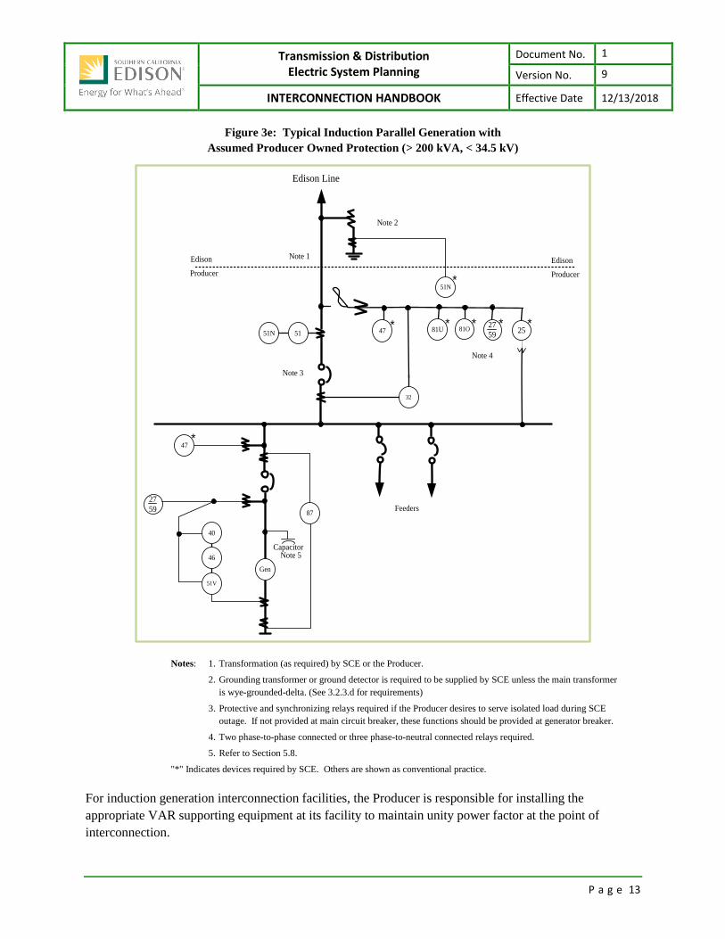
Figure 3e: Typical Induction Parallel Generation with
Assumed Producer Owned Protection (> 200 kVA, < 34.5 kV)
Feeders
Edison Line
Note 2
81O81U
32
Note 1
2527
5947
* * * * *51
Note 3
Note 4
47
Gen
87
46
40
27
59
51V
Note 5Capacitor
*
51N
51N*
Edison
Producer
Edison
Producer
Notes: 1. Transformation (as required) by SCE or the Producer.
2. Grounding transformer or ground detector is required to be supplied by SCE unless the main transformer
is wye-grounded-delta. (See 3.2.3.d for requirements)
3. Protective and synchronizing relays required if the Producer desires to serve isolated load during SCE
outage. If not provided at main circuit breaker, these functions should be provided at generator breaker.
4. Two phase-to-phase connected or three phase-to-neutral connected relays required.
5. Refer to Section 5.8.
"*" Indicates devices required by SCE. Others are shown as conventional practice.
For induction generation interconnection facilities, the Producer is responsible for installing the
appropriate VAR supporting equipment at its facility to maintain unity power factor at the point of
interconnection.
Transmission & Distribution Electric System Planning
Document No. 1
Version No. 9
INTERCONNECTION HANDBOOK Effective Date 12/13/2018
P a g e 14
Figure 3f: Typical Parallel Generation Utilizing Inverter Technology
With Assumed Producer Owned Protection (≥ 200 KVA, ≤ 34.5 kV)
Producer’s Feeders
And
Other Inverter Circuits
47
27
59
81U
81O
Edison
Producer
Note 3
Note 1
and 2
Generator
Contactor
Inverter
Generator
Feeder CB
Edison
Line
Generator(s) Utilizing
Inverter Technology
Isolation
Transformer
Load Break
SwitchNote 4
Note 5
Notes: 1. Protective devices required by SCE for all installations. 𝟐𝟕
𝟓𝟗 shall be a 3Ø unit or two 1Ø units.
2. UL1741 certified inverters meet noted protection requirements without additional relays provided all
inverters are UL1741 compliant.
3. Recommended for three phase generators.
4. Transformation as required by SCE or the Producer.
5. Load break switch to be installed when required by SCE’s Distribution Design Standards.
6. Drawing does not show metering requirements.
7. Producer is responsible for other protective devices not shown on the diagram because of large
variations with type of inverter.
3.2.1 The Producer shall provide adequate protective devices
Detect and clear the generator(s) from short circuits or grounds on SCE’s electric
system serving the Producer.

Transmission & Distribution Electric System Planning
Document No. 1
Version No. 9
INTERCONNECTION HANDBOOK Effective Date 12/13/2018
P a g e 15
Detect the voltage and frequency changes that can occur if the SCE electric system
serving the Producer is disconnected from the main system, and clear the Producer's
generating facilities from the islanded system.
Prevent reparalleling the Producer's generation, after an incident of trouble, unless the
SCE service voltage has been of normal magnitude and frequency continuously for a
pre-determined period of time (typically five minutes).
3.2.2 Protection devices which may be required to satisfy the above Requirements
Phase over-current trip devices (Device 51, 51V, or 67V)
In most cases these will have to be voltage-restrained or voltage-controlled over-
current relays in order to provide coordination with SCE relays.
Residual over-current or over-voltage relays to trip for ground faults on the SCE
electric system (Devices 51N or 59G)
The required type of device (51N or 59G) depends on the characteristic of SCE's
interconnecting system. Contact SCE for information for a specific location.
Under/over voltage relays (Device 27/59)
Two over/under voltage relays measuring different phase-to-phase voltages or three
over/under voltage relays each measuring a phase-to-neutral voltage is required. A
single multiphase over/under voltage relay is acceptable if it has separate voltage
measurement elements for each phase or phase pair. Under voltage relays should be
adjustable from 75-90% of nominal voltage and have time delay to prevent
unnecessary tripping on external faults. Over voltage relays should be adjustable
from 110-120% of nominal voltage and be instantaneous or a combination of
instantaneous and time delayed. Setting changes with temperature variation should
not exceed +2 volts over the expected temperature range.
Under/over frequency relays (Device 81-O or 81-U)
The under-frequency relay should be adjustable per the applicable standards (e.g.
CAISO, NERC, and IEEE) requirements and regional requirements (WECC).
Setting change with temperature variation over the expected range, or voltage
variation over +10%, should not exceed +0.05 Hz.
Phase sequence under-voltage relay (Device 47/27)
To permit paralleling only when SCE voltage and phase sequence are normal.
Automatic Separation: In some cases, protective devices supplied with the
generating equipment will meet some or all of these Requirements, provided that it is
acceptable to trip the generator whenever the SCE source is lost. If the Producer
desires to automatically separate from SCE and commence isolated operation upon
loss of the SCE source, additional devices will be necessary to effect the separation.
Large Generators: In specific installations, particularly with large generators (over
10,000 kVA), SCE may require specific additional protection functions such as loss

Transmission & Distribution Electric System Planning
Document No. 1
Version No. 9
INTERCONNECTION HANDBOOK Effective Date 12/13/2018
P a g e 16
of excitation, loss of synchronism and over-excitation protection, if these conditions
would have an impact on SCE’s electric system.
3.2.3 Other protection devices for Category 2 Generation
Utility Quality Relays: Depending on the size of the generating facility and the size
of the distribution or subtransmission system to which it is connected, SCE may
require the Producer to utilize "utility quality" protective relays. Such relays have
more stringent tolerances and more widely published characteristics than "industrial
quality" relays and have the ability to coordinate protective settings with utility
settings. This Requirement will be invoked only if the generating facility is large
enough to require close coordination with SCE relays. In general, installations
aggregating less than 1,000 kVA will not be subject to this Requirement.
Relay Operation Recorders: All protective devices supplied to satisfy the
Requirements in Category 2 generating facilities shall be equipped with operation
indicators (targets) or shall be connected to an annunciator or event recorder so that it
will be possible to determine, after the fact, which devices caused a particular trip.
Relay Testing: All protective devices supplied to satisfy the Requirements in this
Category shall be tested by qualified personnel prior to SCE approving parallel
operation, and at intervals at least as frequent as those used by SCE for the relays
protecting the line(s) serving the Producer. Special tests may also be requested by
SCE to investigate apparent missed operations. Each routine or special test shall
include both a calibration check and an actual trip of the circuit breaker from the
device being tested. For each test a report shall be prepared and sent to SCE listing
the tests made and the "as found" and "as left" settings/calibration values.
Four-wire Multi-grounded Neutral Distribution Circuits: In projects where the
Producer is served from an SCE four-wire multi-grounded neutral distribution circuit,
adequate grounding must be provided to ensure neutral stability during accidental
isolation of the line from the main system. This is necessary to avoid dangerous
over-voltages on other customers served from phase-to-neutral connected distribution
transformers. Adequate grounding can be provided either by the use of a wye-delta
main power transformer or by installing an appropriate grounding transformer. In
order to limit the effects of such grounding on SCE's ground relay sensitivity, SCE
may require that the grounding impedance be limited to the highest value suitable for
neutral stabilization.
3.2.4 Exemption For Installing Phase Over-current Protective Devices Where induction generators or static inverters are employed rather than synchronous machines,
the phase over-current protective devices required by SCE generally will be waived since these
generation sources will not deliver sustained over-currents. All other specified protective devices
are required.

Transmission & Distribution Electric System Planning
Document No. 1
Version No. 9
INTERCONNECTION HANDBOOK Effective Date 12/13/2018
P a g e 17
Category 3: Total Generation Less Than 200 kVA, in Voltage at 34.5kV & Below The following Requirements for small generating facilities are based on an assumed low density of
parallel generation on the serving circuit. Other Requirements may be imposed should the density exceed
a tolerable limit. Refer to Figure 3g and Figure 3h.
Figure 3g: Typical Parallel Generation Under 200 kVA
Producer’s Feeders
And
Other Branch Circuits
47
27
59
81U
81O Gen
Note 3
Note 1
and 2
Generator
Contactor
Generator
Feeder CB
Edison Line
Note 2 M
M
Notes: 1. Protective devices required by SCE for all installations. Other protective devices for
generator not shown because of large variations with type of generator.
2. Self-contained metering is typical.
3. Required for three phase generators.
Transmission & Distribution Electric System Planning
Document No. 1
Version No. 9
INTERCONNECTION HANDBOOK Effective Date 12/13/2018
P a g e 18
Figure 3h: Typical Parallel Generation Utilizing Inverter Technology
With Assumed Producer Owned Protection (< 200 KVA, ≤ 34.5 kV )
Producer’s Feeders
And
Other Inverter Circuits
47
27
59
81U
81O
Edison
Producer
Note 3
Note 1
and 2
Generator
Contactor
Inverter
Generator
Feeder CB
Edison
Line
Generator(s) Utilizing
Inverter Technology
Isolation
Transformer
Load Break
SwitchNote 4
Note 5
Notes: 1. Protective devices required by SCE for all installations. 𝟐𝟕
𝟓𝟗 shall be a 3Ø unit or two 1Ø units.
2. UL1741 certified inverters meet noted protection requirements without additional relays provided all inverters are UL1741 compliant.
3. Recommended for three phase generators.
4. Transformation as required by SCE or the Producer.
5. Load break switch to be installed when required by SCE’s Distribution Design Standards.
6. Drawing does not show metering requirements.
7. Producer is responsible for other protective devices not shown on the diagram because of large
variations with type of inverter.

Transmission & Distribution Electric System Planning
Document No. 1
Version No. 9
INTERCONNECTION HANDBOOK Effective Date 12/13/2018
P a g e 19
Line Voltage Relay or Contactor: Producer generator controls are to be equipped
with a line voltage relay or contactor which will prevent the generator from being
connected to a de-energized or single-phased (if normally three-phase) source. This
relay is to disconnect the generator from a de-energized utility line and prevent its
reconnection until the line has been re-energized by SCE and has maintained nominal
voltage and frequency continuously for a pre-determined period of time (typically five
minutes).
Relays to Detect Islanding: Producer generators are to be equipped with over/under
frequency and over/under voltage relays for islanding detection. These relays must
meet the specifications listed in Section 3.2.2, paragraphs (c) and (d). The relays
may be arranged to de-energize the contactor as shown in Figure 3f. The Producer
generator islanding protection must be able to detect an islanded condition and cease
to energize SCE’s distribution system within two seconds. Other requirements may
be imposed on those installations unable to meet this requirement.
Fault Detection: The Producer shall provide adequate protective relays to detect and
clear the generator(s) from short circuits or grounds on SCE’s electric system serving
the Producer.
Four-wire Multi-grounded Neutral Distribution Circuits: In projects where the
Producer is served from an SCE four-wire multi-grounded neutral distribution circuit,
adequate grounding must be provided to ensure neutral stability during accidental
isolation of the line from the main system.

Transmission & Distribution Electric System Planning
Document No. 1
Version No. 9
INTERCONNECTION HANDBOOK Effective Date 12/13/2018
P a g e 20
Figure 3i: Typical Relay/Contactor Arrangement Under 200 kVA
This drawing is intended to show the relay/contactor arrangement only. Other over-current
or switching devices may be required by local authorities.
Generator &
Controls
L1 L2 L3
Note 2
T1
T2
47
47 81 2759
4
2759
81
Note 1
Note 1
Note 147
Notes: 1. Contacts closed with normal voltage, frequency and phase sequence.
2. Control transformers as required to match relay/contactor voltage to supply voltage.
Arrangement shown is for three phase system. For single phase omit L3, T1, Dev. 47.

Transmission & Distribution Electric System Planning
Document No. 1
Version No. 9
INTERCONNECTION HANDBOOK Effective Date 12/13/2018
P a g e 21
Dedicated Distribution Transformer: SCE may require the Producer to be served
through a dedicated distribution transformer which serves no other customers. The
purpose of the dedicated transformer is to confine any voltage fluctuations or
harmonics produced by the generators to the Producer's own system.
Harmonic Requirements for Inverters: See “Voltage Imbalance and Abnormal
Voltage or Current Waveforms” Section 5.10.
SCE Telecommunications: Typically not required for protective purposes in
Category 3 generating facilities except as required to coordinate with SCE’s
protective relays.
Exception to Protection Devices: Producers generating facilities may, as an
alternative to the Requirements specified in this Category 3 generating facility
section above, utilize an approved inverter/interface device meeting applicable safety
and performance standards established by the National Electrical Code, the Institute
of Electrical and Electronics Engineers (“IEEE”), and accredited testing laboratories
such as Underwriters Laboratories (“UL”). These Requirements include, but are not
limited to, the provisions of IEEE Standard 929, IEEE Standard 1547, and UL
Standard 1741.
Breaker Duty and Surge Protection
3.4.1 SCE Duty Analysis The recognized standard for circuit breakers rated on a symmetrical current basis is IEEE
Standard C37.010-1999(R2005), "IEEE Application Guide for AC High-Voltage Circuit Breakers
Rated on a Symmetrical Current Basis," and ANSI/IEEE Standard C37.5 for circuit breakers
rated on a total current basis. SCE will review breaker duty and surge protection to identify any
additions required to maintain an acceptable level of SCE system availability, reliability,
equipment insulation margins, and safety. Also, the management of increasing short-circuit duty
of the transmission system involves selecting the alternative that provides the best balance
between cost and capability. System arrangements must be designed so that the interrupting
capability of available equipment is not exceeded.
When studies of planned future system arrangements indicate that the short-circuit duty will reach
the capability of existing breakers, consideration should be given to the following factors:
Methods of limiting duty to the circuit breaker capability, or less:
1. De-looping or rearranging transmission lines at substations;
2. Split bus arrangements.
Magnitude of short circuit duty.
The effect of future projects on the duty.
Increasing the interrupting capability of equipment.
The ability of a particular breaker to interrupt short circuits considering applicable
operating experience and prior test data.
Transmission & Distribution Electric System Planning
Document No. 1
Version No. 9
INTERCONNECTION HANDBOOK Effective Date 12/13/2018
P a g e 22
Please note that SCE performs an annual short circuit duty analysis, which may include
reevaluation of the facility breakers.
3.4.2 Customer Owned Duty/Surge Protection Equipment In compliance with Good Utility Practice and, if applicable, the Requirements of SCE’s
Interconnection Handbook, the Producer shall provide, install, own, and maintain relays, circuit
breakers and all other devices necessary to remove any fault contribution of the generation
facility to any short circuit occurring on SCE’s electric system not otherwise isolated by SCE’s
equipment, such that the removal of the fault contribution shall be coordinated with the protective
requirements of SCE’s electric system. Such protective equipment shall include, but not limited
to, a disconnecting device and a fault current-interrupting device located between the generation
facility and the SCE electric system at a site selected upon mutual agreement (not to be
unreasonably withheld, conditioned or delayed) of the Parties. The Producer shall be responsible
for protection of the generation facility and other equipment from such conditions as negative
sequence currents, over- or under-frequency, sudden load rejection, over- or under-voltage, and
generator loss-of-field. The Producer shall be solely responsible to disconnect their facility if
conditions on SCE’s electric system are impacted by the generation facility.
Underfrequency Relays For voltage classes 161 kV and above, it is essential that the underfrequency protection of generating
units and any other manual or automatic actions are coordinated with underfrequency load shedding relay
settings. For further information, please refer to Section 3.2.2.d.
Since the facilities of SCE’s electric system may be vital to the secure operation of the Interconnection,
CAISO/SCE shall make every effort to remain connected to the Interconnection. However, if the system
or control area determines that it is endangered by remaining interconnected, it may take such action as it
deems necessary to protect the system.
Intentional tripping of tie lines due to underfrequency is permitted at the discretion of SCE’s electric
system, providing that the separation frequency is no higher than 57.9 Hz with a one second time delay.
While acknowledging the right to trip tie lines at 57.9 Hz, the preference is that intentional tripping not be
implemented.

Transmission & Distribution Electric System Planning
Document No. 1
Version No. 9
INTERCONNECTION HANDBOOK Effective Date 12/13/2018
P a g e 23
SECTION 4 MISCELLANEOUS REQUIREMENTS:
Power System Stabilizers (PSS) All new Producers' synchronous generators, larger than 30 MVA and interconnecting at a voltage 60 kV
or higher are required to install PSS with a suitable excitation system, unless an exemption has been
obtained from WECC. Suitable excitation systems are defined in the WECC report; "Criteria to
Determine Excitation System Suitability for PSS," dated December 1992.
Unless an exemption has been received from the WECC, all new generators are assumed suitable for PSS,
and must abide by the following Requirements:
The generator excitation system must be equipped with a power system stabilizer
(PSS). The PSS improves stability in the electrical system when system power
disturbances occur.
The PSS equipment must be approved by SCE prior to installation and operation.
The PSS must be calibrated and operated in accordance with WECC standard
procedures for calibration, testing, and operation of PSS equipment.
Calibration and test reports must be submitted to SCE for review and approval. The
generating facility shall not be considered operational until calibration of the PSS has
been performed to SCE's satisfaction.
The PSS shall be properly maintained and in service when the generator is on line for
power production.
In addition to the foregoing Requirements, Producers must conform to all applicable current or
future WECC Criteria. Specific to PSS, these Criteria currently include “WECC Power System
Stabilizer Design and Performance Criteria,” approved by the Technical Operations
Subcommittee, September 15, 2003.
Governor “Droop” Shall Be Set At 5% All new Producers’ generators having suitable systems must comply with the WECC minimum operating
reliability criteria for governor droop.
These Requirements are necessary to provide an equitable and coordinated system response to
load/generation imbalances. Governor droop shall be set at 5%. Governors shall not be operated with
excessive dead-bands, and governors shall not be blocked unless required by regulatory mandates.
Wind Turbine Generating Facilities
4.3.1 Wind Turbine Set-Back Criteria
The Producer shall locate its wind-driven generating unit such that it does not
encroach onto SCE transmission right of way or edge of any electric operating
property.
The Producer shall be responsible for performing its appropriate grounding
requirements for its wind-driven generating units.

Transmission & Distribution Electric System Planning
Document No. 1
Version No. 9
INTERCONNECTION HANDBOOK Effective Date 12/13/2018
P a g e 24
4.3.2 Generator Electric Grid Fault Ride-Through Capability and Power Factor Criteria SCE currently supports a Low Voltage Ride-Through1 Criterion that the WECC has adopted to
ensure continued reliable service. The Criteria are summarized as follows:
Generator is to remain in-service during system faults (three phase faults with normal
clearing and single-line-to-ground with delayed clearing) unless clearing the fault
effectively disconnects the generator from the system.
During the transient period, the generator is required to remain in-service for the low
voltage and frequency excursions specified in WECC Disturbance-Performance
Table of “Allowable Effects on Other Systems” as applied to load bus constraint.
These performance criteria are applied to the generator interconnection point, not the
generator terminals.
Generators may be tripped after the fault period if this action is intended as part of a
Remedial Action Scheme.
This Standard will not apply to individual units or to a site where the sum of the
installed capabilities of all machines is less than 10MVA, unless it can be proven that
reliability concerns exist.
The performance criterion of this Standard may be satisfied with performance of the
generators or by installing equipment to satisfy the performance criteria.
The performance criterion of this Standard applies to any generation independent of
the interconnected voltage level.
No exemption from this Standard will be given because of minor impact to the interconnected
system. This criterion also applies to existing generators that go through any refurbishments or
any replacements.
Reclosing Circuit Breakers and Hot Line Reclose Blocking Because most short circuits on overhead lines are of a temporary nature, it is SCE's practice to reclose the
circuit breakers on such lines within a few seconds after they have automatically tripped. This practice
improves continuity of service to all SCE's customers. The protective relays specified by SCE for parallel
generation interfaces are intended to disconnect the generating facilities from faulty or isolated lines before
reclosing occurs. Should the Producer desire additional protection against the possibility that reclosing might
occur with his generator still connected to the line (a potentially damaging occurrence for synchronous
generators), SCE can provide, at the Producer’s expense, "Hot Line Reclose Blocking" at the necessary points
on its system. Transfer trip protection may be required to facilitate restoration of service to SCE’s customers.
SCE's preference is to avoid such equipment because of the possible adverse effects on service continuity and
the problems of moving or rearranging the equipment to accommodate system changes. Costs for installing,
maintaining, and/or rearranging such equipment will be borne by the Producer(s) requesting the equipment.
1 Ride-through - A generating plant remaining connected and continuing to generate current after a voltage or
frequency disturbance.

Transmission & Distribution Electric System Planning
Document No. 1
Version No. 9
INTERCONNECTION HANDBOOK Effective Date 12/13/2018
P a g e 25
Unbalanced Currents Producers with three-phase generators should be aware that certain conditions in the utility system may
cause negative sequence currents to flow in the generator. It is the sole responsibility of the Producer to
protect its equipment from excessive negative sequence currents.
Sub-Synchronous Interaction Evaluations Generators interconnected within electrical proximity of series capacitor banks on the transmission
system or Flexible Current Transmission Systems (FACTS) are susceptible to Sub-Synchronous
Interaction (SSI) conditions which must be evaluated. Sub-Synchronous Interaction evaluations include
Sub-Synchronous Resonance (SSR) and Subsynchronous Torsional Interactions (SSTI) for conventional
generation units, and Subsynchronous Control Instability (SSCI) for inverter based generators using
power electronic devices (e.g. Solar PV and Wind Turbines).
A study must be performed to evaluate the SSI between generating facilities and the transmission system
for projects interconnecting in close electrical proximity of series capacitor banks on the transmission
system or FACTS devices to ensure that the Generator Project does not damage SCE’s control systems.
The SSI study may require that the IC provide a detailed PSCAD model of its Generating Facility and
associated control systems, along with the manufacturer representative's contact information. The study
will identify any mitigation(s) that will be required prior to initial synchronization of the Generating
Facility. The study and the proposed mitigation(s) shall be at the expense of the IC.
The Interconnection Customer is 100% responsible for the cost associated with SSI studies and
mitigations. It is the IC’s responsibility to select, purchase, and install turbine/inverter based generators
that are compatible with the series compensation in the area and the FACTS devices.
4.6.1 Sub-Synchronous Resonance Studies SSR occurs when the network natural frequencies (below fundamental frequencies) coincide with
the turbine-generator torsional-mode frequencies causing the turbine-generator to stress that may
result in shaft failure. The turbine-generator and the system may interact with SSR into two main
ways: Torsional Interaction (TI) and Torque Amplification (TA). In order to evaluate a potential
SSR condition on a new generator installation near series compensated lines or FACTS devices a
screening study needs to be conducted to identify any TA or TI impact on the series
compensation level or FACTS devices controls. If a case is identified by the initial screening
process (Frequency Scanning Study) a more detailed time domain study is required to quantify
the potential damage and provide with mitigation measures.
4.6.2 Sub-Synchronous Control Interaction Studies SSCI risk occurs on zero-crossing reactance when going from negative (capacitive) to positive
(inductive) reactance. In order to evaluate a potential SSCI condition on a new generator
installation near series compensated lines or FACTS devices a screening is performed through
impedance scans looking out into the system from the inverter based plant, with the plant
disconnected. If a case is identified by the initial screening process, a more detailed study is
required to quantify the potential damage and provide with mitigation measures.
Transmission & Distribution Electric System Planning
Document No. 1
Version No. 9
INTERCONNECTION HANDBOOK Effective Date 12/13/2018
P a g e 26
Voltage Control Generating units 10 MVA and larger shall be equipped with automatic voltage control equipment. All
generating units with automatic voltage control equipment shall normally be operated in voltage control
mode. These generating units shall not be operated in other control modes (e.g., constant power factor
control) unless authorized to do so by the balancing authority. The control mode of generating units shall
be accurately represented in operating studies.
All new Producers' synchronous generators, regardless of size and interconnecting at a voltage 55kV or
higher, must abide by the following Requirements:
The synchronous generator shall have an excitation system with a continuously acting
Voltage Control equipment.
The Voltage Control equipment must be approved by SCE prior to installation and
operation.
The Voltage Control equipment must be calibrated and operated in accordance with
WECC standard procedures for calibration, testing, and operation of Voltage Control
equipment.
Calibration and test reports must be submitted to SCE for review and approval. The
generating facility shall not be considered operational until calibration of the Voltage
Control has been performed to SCE's satisfaction.
The Voltage Control equipment shall be properly maintained and in service when the
generator is on line for power production.
Automatic voltage control equipment on generating units, synchronous condensers, and Flexible
Alternating Current Transmission System (FACTS) shall be kept in service to the maximum extent
possible with outages coordinated to minimize the number out of service at any one time. Such voltage
control equipment shall operate at voltages specified by either the
California Independent System Operator (CAISO) for generators directly connected
to SCE owned portions of the Bulk Electric System; or
SCE for generators connected to SCE’s Local Distribution System, which are
facilities not under CASIO operational control.
Insulation Coordination Insulation coordination is the selection of insulation strength and practice of correlating insulation levels
of equipment and circuits with the characteristics of surge-protective devices such that the insulation is
protected from excessive overvoltages. Insulation coordination must be done properly to ensure electrical
system reliability and personnel safety.
The Producer shall be responsible for an insulation coordination study to determine appropriate surge
arrester class and rating on the generating facility’s equipment. In addition, the Producer is responsible for
the proper selection of substation equipment and their arrangements from an insulation coordination
standpoint.

Transmission & Distribution Electric System Planning
Document No. 1
Version No. 9
INTERCONNECTION HANDBOOK Effective Date 12/13/2018
P a g e 27
Basic Surge Level (BSLs), surge arrester, conductor spacing and gap application, substation and
transmission line insulation strength, protection, and shielding shall be documented and submitted for
evaluation as part of the interconnection plan.
Ratings
4.9.1 Facility Ratings The ratings of facilities are the responsibility of the owner of those facilities. Ratings of facilities
must conform to current NERC Reliability Standard governing Facility Ratings.
4.9.2 Ratings Provided by Equipment Manufacturers Equipment installed on SCE’s electric system is rated according to the manufacturer’s nameplate
or certifications, and ANSI/IEEE standards. The manufacturer’s nameplate rating is the normal
rating of the equipment. ANSI/IEEE standards may allow for emergency overloads above the
normal rating under specified conditions and often according to an engineering calculation.
Emergency loading may impact the service life of the equipment. In some cases the manufacturer
has certified equipment for operation at different normal or emergency loads based on site-
specific operation conditions. Older technology equipment is rated according to the standards
under which it was built unless the manufacturer, ANSI/IEEE standards, or SCE’s determination
indicates that a reduced rating is prudent or an increase rating is justified.
4.9.3 Rating Practice The normal and emergency ratings of transmission lines or the transformation facilities shall
equal the least rated component in the path of power flow.
4.9.4 Ambient Conditions Since SCE’s territory is in a year-round moderate climate, SCE does not establish equipment
ratings based on seasonal temperatures. That is, SCE standard ratings for normal and emergency
ratings are the same throughout the year and reflect summer ambient temperatures coincident
with ANSI/IEEE standards, i.e., 40°C (104°F). However, in some cases SCE may calculate site-
specific ratings that consider the local ambient conditions based on ANSI/IEEE rating methods.
4.9.5 Transmission Lines The transmission circuit rating is determined according to the least rated component in the path of
power flow. This comprises of the transmission line conductor/cable, the series devices in the
line, the allowable current that will not cause the conductors to sag below allowable clearance
limits, the allowable current that will not cause the cables to operate above the designed
temperature limit, and the termination equipment.
4.9.6 Overhead Conductors The transmission line conductor ratings are calculated in accordance with latest applicable
version of the ANSI/IEEE 738 For Aluminum Conductor Steel Reinforced (ACSR) conductor the
normal conductor rating allows a total temperature of 90°C and the emergency rating allows
135°C. Similarly, for aluminum and copper conductors SCE permits 85°C and 130°C. For
Aluminum Conductor Steel Supported (ACSS), SCE base the normal rating at 120°C, and 200°C
Transmission & Distribution Electric System Planning
Document No. 1
Version No. 9
INTERCONNECTION HANDBOOK Effective Date 12/13/2018
P a g e 28
for the emergency rating. Higher or lower temperature limits may be permitted as appropriate
depending on engineering justification.
4.9.7 Underground Cable The transmission line cable ratings are calculated in accordance with IEC 60287. For cross-linked
polyethylene (XLE) insulated cable, the normal cable rating allows a total temperature of 90°C
and the emergency rating allows 105°C for 4 hours. Higher or lower temperature limits may be
permitted as appropriate depending on engineering justification and/or component tested data.
4.9.8 Series and Shunt Compensation Devices Series capacitor and reactors are only permitted to be loaded to ANSI/IEEE limits or as specified
by the manufacturer. VAR compensators shall be rated according to the ANSI/IEEE standards
where applicable and according to the manufacturer’s limitations. These ratings are reported to
CAISO Transmission Register. Shunt capacitors and reactors are not in the path of power flow so
they are not directly a “limiting component.” However, their reactive power capacity is reported
to CAISO Transmission Register.
4.9.9 Terminal Equipment Terminal equipment comprises: circuit breakers, disconnect switches, jumpers, drops, conductors,
buses, and wave-traps, i.e., all equipment in the path of power flow that might limit the capacity
of the transmission line or transformer bank to which it is connected. The normal and emergency
ampere rating for each termination device is reported to CAISO in its Transmission Register.
4.9.10 Transformer Bays The rating of a transformer bay is determined by the least rated device in the path of power flow.
This comprises ratings of the transformer, the transformer leads, the termination equipment, and
reduced parallel capacity where applicable. The transformer rating is compared to the termination
equipment ratings and lead conductors to establish the final transformation rating based on the
least rated component..
4.9.11 Transformer Normal Ratings The “normal” rating is the transformer’s highest continuous nameplate rating with all of its
cooling equipment operating. The only exception is when a special “load capability study” has
been performed showing that a specific transformer is capable of higher than nameplate loading
and for which the test data or calculations are available.
4.9.12 Transformer Emergency Ratings A transformer’s emergency rating is arrived at by one of two methods. First, if no overload tests
are available then a 10% overload is allowed. Second, if a factory heat-run or a load capability
study has been performed, the emergency rating may be as high as 20% above normal as revealed
by the test. For transformers on the transmission system, i.e., primary voltage of 500 kV, the short
term load limit (STELL) is 1-hour and the allowed duration of the long term emergency load limit
(LTELL) is 24-hours. For transformers with primary voltage of 161 kV to 220 kV, the short term
load limit (STELL) is 1-hour and the allowed duration of the long term emergency load loading
limit (LTELL) is thirty days.

Transmission & Distribution Electric System Planning
Document No. 1
Version No. 9
INTERCONNECTION HANDBOOK Effective Date 12/13/2018
P a g e 29
4.9.13 Parallel Operation of Transformers When two or more transformers are operated in parallel, consideration is given to load split due to
their relative impedances such that full parallel capacity is not usually realized. The permissible
parallel loading is calculated according to ANSI/IEEE standards.
4.9.14 Relays Protective Devices In cases where protection systems constitute a loading limit on a facility, this limit is the rating
for that facility. These limiting factors are reported to the CAISO Transmission Register and are
so noted as to the specific reason, e.g., “limited to 725A by relay setting.”
4.9.15 Path Ratings As stated in Section 2 of the WECC Procedures for Project Rating Review, new facilities and
facility modifications should not adversely impact accepted or existing ratings regardless of
whether the facility is being rated. New or modified facilities can include transmission lines,
generating plants, substations, series capacitor stations, remedial action schemes or any other
facilities affecting the capacity or use of the interconnected electric system.
Synchronizing of Facilities Testing and synchronizing of a generation facility may be required depending on SCE’s electric system
conditions, ownership or policy, and will be determined based on facility operating parameters. Such
procedures should provide for alternative action to be taken if lack of information or loss of
communication channels would affect synchronization.
Appropriate operating procedures and equipment designs are needed to guard against out-of-sync closure
or uncontrolled energization. (Note: SCE’s transmission lines utilize ACB phase rotation, which is
different than the national standard phase rotation). The Producer is responsible to know and follow all
applicable regulations, industry guidelines, safety requirements, and accepted practice for the design,
operation and maintenance of the facility.
Synchronizing locations shall be determined ahead of time; required procedures shall be in place and be
coordinated with SCE. SCE and the Producer shall mutually agree and select the initial synchronization
date. The initial synchronization date shall mean the date upon which a facility is initially synchronized to
the SCE’s electric system and upon which trial operation begins.
For additional technical information regarding the synchronizing of generators refer to Section 3
Protection Requirements.
Maintenance Coordination and Inspection The security and reliability of the interconnected power system depends upon periodic inspection and
adequate maintenance of the generation facility and associated equipment, including but not limited to
control equipment, communication equipment, relaying equipment and other system facilities. Entities
and coordinated groups of entities shall follow CAISO procedures and are responsible for disseminating
information on scheduled outages and for coordinating scheduled outages of major facilities which affect
the security and reliability of the interconnected power system.

Transmission & Distribution Electric System Planning
Document No. 1
Version No. 9
INTERCONNECTION HANDBOOK Effective Date 12/13/2018
P a g e 30
Abnormal Frequency and Voltages
4.12.1 Joint Reliability Procedures Where specific transmission issues have been identified, those entities affected by and those
entities contributing to the problem shall develop joint procedures for maintaining reliability.
4.12.2 Voltage and Reactive Flows CAISO shall coordinate the control of voltage levels and reactive flows during normal and
Emergency Conditions. All operating entities shall assist with the CAISO’s coordination efforts.
4.12.3 Transfer Limits Under Outage and Abnormal System Conditions In addition to establishing total transfer capability limits under normal system conditions,
transmission providers and balancing authority shall establish total transfer capability limits for
facility outages and any other conditions such as unusual loads and resource patterns or power
flows that affect the transfer capability limits.
Communications and Procedures
4.13.1 Use of Communication System It is essential to establish and maintain communications with the SCE Grid Control Center
(GCC), the Alternate Grid Control Center (AGCC) or a jurisdictional Switching Center should a
temporarily attended station or area of jurisdiction become involved in a case of system trouble. It
is equally important that communication services be kept clear of nonessential use during times of
system trouble to facilitate system restoration or other emergency operations.
4.13.2 Remedial Action Schemes Communication Equipment Requirements Generation facilities will require the necessary communication equipment for the implementation
of Remedial Action Schemes (RAS). This equipment provides line monitoring and high-speed
communications between the Generation Facility breaker and the central control facility, utilizing
applicable protocols. RASs may also be applied to generators that may be required to trip in order
to relieve congestion on SCE’s electric system. Thus, allowing a RAS to incorporate
disconnection into automatic control algorithms under contingency conditions, as needed.
RASs are fully redundant systems. The following paragraph is an excerpt from the WECC
Remedial Action Scheme Design Guide that specifies the Philosophy and General Design Criteria
for RAS redundancy. “Redundancy is intended to allow removing one scheme following a failure
or for maintenance while keeping full scheme capability in service with a separate scheme.
Redundancy requirements cover all aspects of the scheme design including detection , arming,
power, supplies, telecommunications facilities and equipment, logic controllers (when
applicable), and RAS trip/close circuits.”
Excerpt from: WECC Remedial Action Scheme Design Guide (11/28/2006)
4.13.3 Critical System Voltage Operation Voltage control during abnormal system configurations requires close attention with
consideration given to what operations will be necessary following loss of the next component.
Voltages approaching 10% above or below the normal value are considered critical with rate of
change being of principal importance.

Transmission & Distribution Electric System Planning
Document No. 1
Version No. 9
INTERCONNECTION HANDBOOK Effective Date 12/13/2018
P a g e 31
SECTION 5 GENERAL OPERATING REQUIREMENTS: System Operating Bulletins: Generator facilities connecting into SCE’s electric
system may be subject to operating requirements established by SCE, the CAISO or
both. SCE’s general operating Requirements are discussed in the sections below.
SCE may also require additional operating Requirements specific to a generator
facility. If so, these Requirements will be documented in SCE’s System Operating
Bulletins (SOB), Substation Standard Instructions (SSI), and/or interconnection and
power purchase agreements. SCE’s SOBs and/or SSIs specific to a generator facility,
and any subsequent revisions, will be provided by SCE to the Producer as they are
made available.
Producer’s Responsibility: It is the Producer’s responsibility to comply with
applicable operating requirements. Operating procedures are subject to change as
system conditions and system needs change. Therefore it is advisable for the
Producer to regularly monitor operating procedures that apply to its generating
facilities. The CAISO publishes its operating procedures on its internet site, but it is
prudent for the Producer to contact the CAISO for specific Requirements.
Quality of Service: The interconnection of the generator facility’s equipment with
SCE’s electric system shall not cause any reduction in the quality of service being
provided to SCE's customers. If complaints result from operation of the generator
facility, such equipment shall be disconnected until the problem is resolved.
SCE Circuits: generator facilities are not permitted to energize any de-energized
SCE circuit.
Operate Prudently: The Producer will be required to operate its facility in accordance
with prudent electrical practices.
Protection in Service: The generating facility shall be operated with all of required
protective apparatus in service whenever the generating facility is connected to, or is
operated in parallel with, the SCE electric system. Redundant protective devices may
be provided at the Producer’s expense if the generator is to be operated in parallel
during routine testing of or failure of a protective device. Any deviation for brief
periods of emergency may only be by agreement of SCE and is not to be interpreted
as permission for subsequent incidents.
Added Facilities Documentation: The Producer may not commence parallel
operation of generator(s) until final written approval has been given by SCE. As part
of the approval process, the Producer shall provide, prior to the commencement of
parallel operation, all documents required by SCE to establish the value of any
facilities installed by the Producer and deeded to SCE for use as added facilities.
SCE reserves the right to inspect the Producer's facility and witness testing of any
equipment or devices associated with the interconnection.
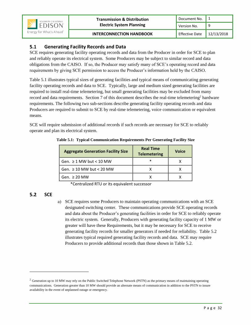
Transmission & Distribution Electric System Planning
Document No. 1
Version No. 9
INTERCONNECTION HANDBOOK Effective Date 12/13/2018
P a g e 32
Generating Facility Records and Data SCE requires generating facility operating records and data from the Producer in order for SCE to plan
and reliably operate its electrical system. Some Producers may be subject to similar record and data
obligations from the CAISO. If so, the Producer may satisfy many of SCE’s operating record and data
requirements by giving SCE permission to access the Producer’s information held by the CAISO.
Table 5.1 illustrates typical sizes of generating facilities and typical means of communicating generating
facility operating records and data to SCE. Typically, large and medium sized generating facilities are
required to install real-time telemetering, but small generating facilities may be excluded from many
record and data requirements. Section 7 of this document describes the real-time telemetering2 hardware
requirements. The following two sub-sections describe generating facility operating records and data
Producers are required to submit to SCE by real-time telemetering, voice communication or equivalent
means.
SCE will require submission of additional records if such records are necessary for SCE to reliably
operate and plan its electrical system.
Table 5.1: Typical Communication Requirements Per Generating Facility Size
Aggregate Generation Facility Size Real Time
Telemetering Voice
Gen. ≥ 1 MW but < 10 MW * X
Gen. ≥ 10 MW but < 20 MW X X
Gen. ≥ 20 MW X X
*Centralized RTU or its equivalent successor
SCE
SCE requires some Producers to maintain operating communications with an SCE
designated switching center. These communications provide SCE operating records
and data about the Producer’s generating facilities in order for SCE to reliably operate
its electric system. Generally, Producers with generating facility capacity of 1 MW or
greater will have these Requirements, but it may be necessary for SCE to receive
generating facility records for smaller generators if needed for reliability. Table 5.2
illustrates typical required generating facility records and data. SCE may require
Producers to provide additional records than those shown in Table 5.2.
2 Generation up to 10 MW may rely on the Public Switched Telephone Network (PSTN) as the primary means of maintaining operating
communications. Generation greater than 10 MW should provide an alternate means of communication in addition to the PSTN to insure
availability in the event of unplanned outage or emergency.

Transmission & Distribution Electric System Planning
Document No. 1
Version No. 9
INTERCONNECTION HANDBOOK Effective Date 12/13/2018
P a g e 33
Table 5.2: Typical Required Generating Facility Records and Data
Generation Facility
Record
Typical Size of Aggregate
Generation3 Facility
Delivery Date or Primary
Communication Mode
Delivery Location
1 System Parallel Operation Or Separation
> 200 kW Timely by Voice Designated SCE Switching Center
2 Scheduled And Unscheduled Outages
> 200 kW Scheduled Outages
Outage Duration Adv. Notice
< 1 day 24 Hours
1 day or more 1 Week
Major overhaul 6 Months
Unscheduled Outages
Timely
Communication Mode
Voice
Designated SCE Switching Center
3 Levels Of Real And Reactive Power
1 MW Real-time Telemetering SCADA
4 Equipment Clearance 10 MW Timely by Voice Designated SCE Switching Center
5 Interruption event > 200 kW Timely after event by Voice Designated SCE Switching Center
6 Gen. Circuit Breaker Status 10 MW Real-time Telemetering SCADA
7 Gen. on/off Status 10 MW Real-time Telemetering SCADA
8 Generator Terminal Voltage 10 MW Real-time Telemetering SCADA
An interruption event is said to occur on an interconnection circuit when its closed
energized circuit breaker has opened or trips and interrupts powerflow to/from SCE
facilities. After experiencing an event, the Producer is required to submit the
following event information to their Designated Switching Center in order for SCE to
assess relay operations and system integrity.
Date and time of trips by the interconnection circuit breaker
Generation facility status at time of incident (real & reactive power
generation)
Relay operation indicator (target) operations
Oscillograph or Sequence of Event recorder records.
3 Aggregate generation is the total nameplate capacity of generating facilities at the generation site being interconnected or the total generation
under one SCE account.

Transmission & Distribution Electric System Planning
Document No. 1
Version No. 9
INTERCONNECTION HANDBOOK Effective Date 12/13/2018
P a g e 34
Operating Data and Records the Producer Must Provide SCE Upon Request
The Producer will be required to keep a daily operations log (records) for the
generating facility which must include levels of operating voltage, relay operations,
information on maintenance outages, maintenance performed, availability, and circuit
breaker trip operations requiring a manual reset. Producers with the necessary
metering4 will be required to log fuel consumption, cogeneration fuel efficiency
kilowatts, kilovars, and kilowatt-hours generated and settings or adjustments of the
generator control equipment and protective devices, and any significant events related
to the operation of the generating facility, including but not limited to real and reactive
power production; changes in operating status and protective apparatus operations;
and any unusual conditions found during inspections. Changes in settings shall also
be logged for Producer's generator(s) if it is "block-loaded" to a specific kW capacity.
SCE, after giving written notice to the Producer, shall have the right to review and
obtain copies of metering records and operations and maintenance logs of the
generating facility.
If a Producer's generating facility has a Nameplate Rating greater than one (1)
megawatt, SCE may require the Producer to report to a designated SCE Switching
Center twice a day at agreed upon times for:
the current day's operation,
the hourly readings in kW of capacity delivered, and
the energy in kWh delivered since the last report.
Calibration of Producer Owned Protective Apparatus The Producer must test the protective apparatus it owns on a routine basis in order to provide correct
calibration and operation of the devices. Required test intervals of these protective apparatus have been
established as shown in Table 5.3.
These test intervals are based on the nominal system voltage at the point of interconnection to SCE. SCE
may require the Producer, at the Producer's expense, to demonstrate to SCE's satisfaction the correct
calibration and operation of the Producer's protective apparatus at any time SCE reasonably believes that
the Producer's protective apparatus may impair the SCE electric system integrity.
4 Generators operating under the FERC QF status have additional metering installed.

Transmission & Distribution Electric System Planning
Document No. 1
Version No. 9
INTERCONNECTION HANDBOOK Effective Date 12/13/2018
P a g e 35
Table 5.3: Required Test Intervals for Protective Devices
Interconnection Voltage Test Interval Delivery Location
1 >200 kV Every two years1 mail to:
Manager, Grid Contracts, P.O. Box 800, 2244 Walnut Grove Avenue, Rosemead, California 91770
2 55 - 200 kV Every four years1 mail to: Same
3 less than 55 kV Every eight years2 mail to: Same
4 Frequency relays
(all voltage levels)
Electromechanical:
Electronic:
Every
two years
four years
mail to: Same
1 The test interval may be extended by 2 years for self-monitoring microprocessor relays
provided with failure alarms, e.g. from four years to six years.
Disconnecting Service to a Generation Facility Applicable agreements and tariffs may state criteria for disconnection of generating facilities which are
interconnected to SCE’s electric system. In general, generating facilities may be curtailed or
disconnected if SCE determines that their operation creates a threat to personnel or the electric system.
Voltage Variations
Voltage Regulation: Operation of the Producer's generating facility shall not
adversely affect the voltage regulation of that portion of SCE’s electric system to
which it is connected. Adequate voltage control shall be provided by the Producer to
minimize voltage regulation on SCE’s electric system caused by changing generator-
loading conditions. The step-up transformer ratio must be chosen such that the
Producer can meet its voltage regulation obligations over the expected range of SCE
system voltages. Step-up transformers must be equipped with no-load taps which
provide +5% adjustment of the transformer ratio in 2.5% steps.
Exception: The tap Requirement will be waived if the Producer submits a study to
SCE which demonstrates to SCE's satisfaction that the Producer can meet its voltage
regulation obligations over the expected range of system voltages specified by SCE.
Generator voltage schedule and transformer tap settings will be specified by SCE, as
necessary, or the CAISO to ensure proper coordination of voltages and regulator
action. It is the Producer’s responsibility to ensure voltage-VAR schedule
compliance. Table 5.4 below identifies whether SCE or the CAISO specifies these
schedules.

Transmission & Distribution Electric System Planning
Document No. 1
Version No. 9
INTERCONNECTION HANDBOOK Effective Date 12/13/2018
P a g e 36
Table 5.4: Electric System Jurisdiction and Tap-setting Specification
Generating Facility Connected to:
CAISO Controlled Transmission System
SCE Controlled Subtransmission or Distribution
Voltage Schedule Specified by CAISO Specified by SCE, as needed
Transformer Tap Settings
Specified by SCE +5% in 2.5% steps
Specified by SCE +5% in 2.5% steps
Transmission Voltages: Expected transmission system operating voltages range
from 160 to 164 kV for 161 kV nominal voltage, 220 to 242 kV for 220 kV nominal
voltage, and 520 to 540 kV for 500 kV nominal voltage. Voltage regulation at a
given location on the transmission system must follow the CAISO and SCE voltage
schedules.
Distribution and Subtransmission Voltages: In order to supply and maintain
proper voltages for SCE's customers as required by the CPUC, SCE's primary
distribution voltages (2.4 to 34.5 kV) and subtransmission voltages (55 to 115 kV)
may fluctuate by as much as +5% from the nominal values (e.g., 12 kV +5%; 34.5
kV +5%; etc.). SCE uses various voltage regulation techniques to raise or lower
primary distribution and subtransmission voltages in order to maintain the customer's
service voltage at the desired level. Producers interconnected at primary distribution
or subtransmission voltage levels must be able to withstand such voltage changes and
to respond with proper power factor adjustment in order not to oppose or interfere
with SCE's or the CAISO’s voltage regulation processes.
VAR Correction VAR correction will normally be planned for light load, heavy load and for system normal and
contingency conditions. This is to be accomplished by providing transmission system VAR correction to
minimize VAR flow and to maintain proper voltage levels. The planning of transmission system VAR
requirements should consider the installation of shunt capacitors, shunt reactors and tertiary shunt
reactors, synchronous condensers, FACTS and transformer tap changers. The guidelines for reactive
planning are as follows:
5.7.1 Interconnection SCE shall not be obligated to supply or absorb reactive power for the generator facility when it
interferes with operation of SCE’s electric system, limits the use of SCE interconnections, or
requires the use of generating equipment that would not otherwise be required.
5.7.2 Subtransmission System VAR correction will normally be planned for connection to 55 kV through 160 kV buses to
correct for large customer VAR deficit, subtransmission line VAR deficit, and transformer A-
Bank VAR losses, the objective being zero VAR flow at the high side of the A-Banks with VAR
flow toward the transmission system on the high side of the A-Banks, if required. Adequate VAR

Transmission & Distribution Electric System Planning
Document No. 1
Version No. 9
INTERCONNECTION HANDBOOK Effective Date 12/13/2018
P a g e 37
correction shall be provided for maximum coincident customer loads (one-in-five year heat storm
conditions), after adjusting for dependable local generation and loss of the largest local bypass
generator.
Voltage Regulation/Reactive Power Supply Requirements Operating entities shall ensure that reactive reserves are adequate to maintain minimum acceptable
voltage limits under facility outage conditions. Reactive reserves required for acceptable response to
contingencies shall be automatically applied when contingencies occur. Operation of static and dynamic
reactive devices shall be coordinated such that static devices are switched in or out of service so that the
maximum reactive reserves are maintained on generators, synchronous condensers and other dynamic
reactive devices.
To ensure secure and reliable operation of the interconnected power system, reactive supply and reactive
generation shall be properly controlled and adequate reactive reserves shall be provided. If power factor
correction equipment is necessary, it may be installed by the Producer at the facility, or by SCE at SCE's
facilities at the Producer’s expense.
Generator VAR schedules, as needed, will be specified by SCE or the CAISO to ensure proper
coordination of voltages. It is the Producer’s responsibility to ensure voltage-VAR schedule compliance.
If power factor correction equipment is necessary, it must be installed by the Producer at its facility at the
Producer’s expense to ensure the power factor at the point of interconnection meets the criteria in Table
5.5.
Note that the generator power factor capability for WDAT service is likely to require equipment capable
of operating over the range of 0.9 lag to 0.95 lead in order to meet the Tariff Point of Delivery
requirements.
Table 5.5: Power Factor Criteria
Generating Facility Connected to:
CAISO Controlled Transmission System SCE Controlled Distribution System*
Power Factor
Synchronous: Generator has the capability of 0.95
lagging to 0.95 leading
Synchronous: Generator has the capability of 0.95 lagging to
0.95 leading at POI
Asynchronous (FERC Order 827): 0.95 lagging to 0.95 leading at high side of
generating station
Asynchronous (FERC Order 827): 0.95 lagging to 0.95 leading at high side of
generating station
* For Rule 21 projects, reference the Rule 21 tariff for power factor requirements.
5.8.1 Reactive Power Equipment – Induction Generators (in aggregate)
5.8.1.1 Facility Reactive Power Equipment Design
Producers shall provide for the supply of its reactive requirements, including appropriate
reactive reserves, and its share of the reactive requirements to support power transfers on

Transmission & Distribution Electric System Planning
Document No. 1
Version No. 9
INTERCONNECTION HANDBOOK Effective Date 12/13/2018
P a g e 38
interconnecting transmission circuits as they relate to their generator facilities.
Reactive power equipment utilized at a generator facility to meet SCE’s Requirements
must be designed to minimize the exposure of SCE's customers, SCE's electric system,
and the electric facilities of others (i.e., other facilities and utilities in the vicinity) to:
severe overvoltages that could result from self-excitation of induction generators,
transients that result from switching of shunt capacitors,
voltage regulation problems associated with switching of inductive and capacitive
devices.
unacceptable harmonics or voltage waveforms, which may include the effect of
power electronic switching, and
Voltage flicker exceeding SCE Voltage Flicker limits as indicated in SCE
Subtransmission Planning Criteria and Guidelines Figure 2-7 “VOLTAGE
FLUCTUATION DESIGN LIMITS”.
5.8.1.2 Facility Reactive Power Equipment Design - provide variable source
The reactive power equipment utilized at a generator facility to meet SCE’s
Requirements must be designed to provide a variable source of reactive power (either
continuously variable or switched in discrete steps). For discrete step changes, the size of
any discrete step change in reactive output shall be limited by the following criteria:
the maximum allowable voltage rise or drop (measured at the point of interconnection
with SCE’s electric system) associated with a step change in the output of a generator
facility’s reactive power equipment must be less than or equal to 1%; and
the maximum allowable deviation from a generator facility’s reactive power schedule
(measured at the point of interconnection with the SCE system) must be less than or
equal to 10% of the generator facility’s maximum (boost) reactive capability.
5.8.2 Reactive Power Supply Requirements - Synchronous Generators Producers connected to SCE’s electric system and utilizing synchronous generators are required
to generate or supply reactive power so that the generating facility does not impose any additional
reactive power demand upon SCE other than the demand of loads within the facility. The
Producer will not be permitted to deliver excess reactive power to SCE under normal operating
conditions unless otherwise agreed to by SCE. Under emergency operating conditions, the
Producer is permitted to deliver excess reactive power to SCE to ensure voltage schedule
compliance.
Producers connected to the subtransmission system or bulk power system (above 34.5 kV) must
have the voltage regulation equipment and generator reactive power capability to maintain a
voltage schedule or reactive power schedule prescribed by SCE or, if applicable, the CAISO.
Generators must be capable of operation over the power factor ranges designated in Table 5.5.

Transmission & Distribution Electric System Planning
Document No. 1
Version No. 9
INTERCONNECTION HANDBOOK Effective Date 12/13/2018
P a g e 39
5.8.3 Reactive Power Supply Requirements - Inverter Systems Forced-commutated inverters must meet SCE’s reactive power supply Requirements of
synchronous generators in 5.8.2. Line commutated inverters must be corrected to satisfy SCE’s
reactive power supply Requirements of induction generators in 5.8.1.
Inverters must also meet SCE’s harmonic load limits based on the latest IEEE Standard 519. For
further information on the assessment and mitigation of harmonics due to inverters, refer to “SCE
Subtransmission Planning Criteria and Guidelines, Appendix C, HARMONIC LOAD LIMITS,
APPLICATION OF IEEE STANDARD 519-1992 TO SUBTRANSMISSION PLANNING”.
5.8.3.1 IEEE and UL Standards for Inverter Systems 200 kVA or Less
Inverter systems which conform to the recommended practices in IEEE Standard 929-19
and which have been tested and approved for conformance to UL Subject 1741, are
considered to have met all SCE’s reactive power supply Requirements.
5.8.4 Voltage and Reactive Control
5.8.4.1 Coordination
Operating entities shall coordinate the use of voltage control equipment to maintain
transmission voltages and reactive flows at optimum levels for system stability within the
operating range of electrical equipment. Operating strategies for distribution capacitors
and other reactive control equipment shall be coordinated with transmission system
requirements.
5.8.4.2 Transmission Lines
Not Applicable to Generation.
5.8.4.3 Switchable Devices
Not Applicable to Generation.
Ride Through Requirements The CAISO is responsible for frequency control and therefore SCE can assume no responsibility for
damage that occurs due to off nominal frequency operation. It is possible that the electrical network
including SCE’s electric system may operate outside of the limits stated above. It is the responsibility of
all Producers connected to SCE’s electric system to install equipment to protect against damage to
Producer owned equipment from off-nominal frequency operation.
Generators that are required to use under-frequency detection for islanding must coordinate frequency
threshold settings to ensure conformance with SCE's abnormal frequency operation plan.
SCE’s Requirements identify three different categories for Producer generating facilities connecting to the
SCE electric system each with distinctive protection Requirements. These categories are:
Off Nominal Frequency and Voltage Ride Through Category 1: Voltage class 34.5 kV and below
Category 2: All BES voltage classes
Category 3: class every other generator not covered by IEEE 1547 or PRC-024-2

Transmission & Distribution Electric System Planning
Document No. 1
Version No. 9
INTERCONNECTION HANDBOOK Effective Date 12/13/2018
P a g e 40
Off Nominal Frequency
5.11.1 Category 1 Producer’s generating facilities connecting at 34.5 kV and below are required to comply with
IEEE 1547 and/or Rule 21 frequency ride through requirements as applicable.
5.11.2 Category 2 Producer’s generating facilities interconnecting to SCE’s Bulk Electric System shall set off
nominal Frequency Protective Relay settings to meet the NERC Reliability Standard PRC-024-2.
5.11.3 Category 3 Producer’s generating facilities that protect for off-nominal frequency operation shall set off
nominal Frequency Protective Relay settings to meet at a minimum the time frames in Table 5.6.
Table 5.6: Off Nominal Frequency Limits
Under Frequency Limit Over Frequency Limit Minimum Time
> 59.4 Hz < 60.6 Hz continuous operating range
< 59.4 Hz > 60.6 Hz 3 minutes
< 58.4 Hz > 61.6 Hz 30 seconds
< 57.8 Hz N/A 7.5 seconds
< 57.3 Hz N/A 45 cycles
< 57.0 Hz ≥ 61.7 Hz may trip instantaneously if required to protect equipment from damage
Frequency relay settings must not allow less stringent operation of the generating facility than
specified in the shown in Table 5.6, unless agreed to in writing by SCE and coordinated with
SCE's abnormal frequency operation plan.
Voltage Ride-Through
5.12.1 Category 1 Producer’s generating facilities connecting at 34.5 kV and below are required to comply with
IEEE 1547 and/or Rule 21 voltage ride through requirements as applicable.
5.12.2 Category 2 Producer’s generating facilities interconnecting to SCE’s Bulk Electric System shall set voltage
Protective Relay settings to meet the NERC Reliability Standard PRC-024-2.
5.12.3 Category 3 Producer’s generating facilities shall set voltage Protective Relay settings to meet at a minimum
the time frames in Table 5.7.
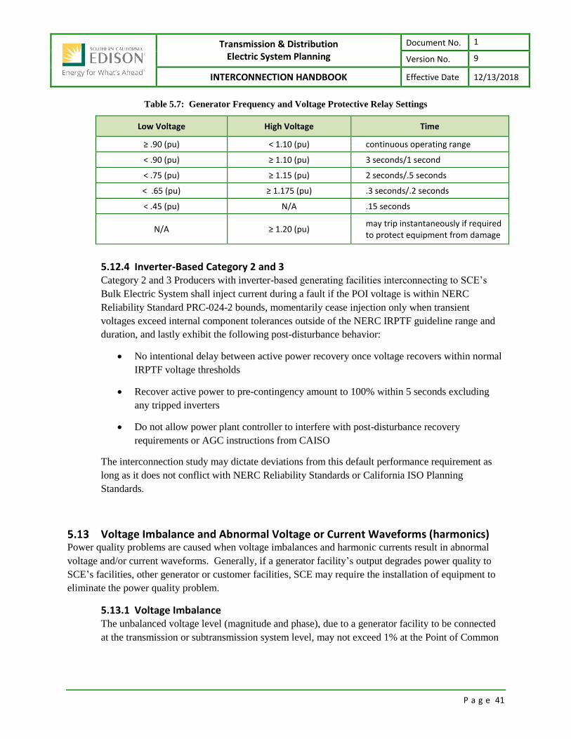
Transmission & Distribution Electric System Planning
Document No. 1
Version No. 9
INTERCONNECTION HANDBOOK Effective Date 12/13/2018
P a g e 41
Table 5.7: Generator Frequency and Voltage Protective Relay Settings
Low Voltage High Voltage Time
≥ .90 (pu) < 1.10 (pu) continuous operating range
< .90 (pu) ≥ 1.10 (pu) 3 seconds/1 second
< .75 (pu) ≥ 1.15 (pu) 2 seconds/.5 seconds
< .65 (pu) ≥ 1.175 (pu) .3 seconds/.2 seconds
< .45 (pu) N/A .15 seconds
N/A ≥ 1.20 (pu) may trip instantaneously if required to protect equipment from damage
5.12.4 Inverter-Based Category 2 and 3 Category 2 and 3 Producers with inverter-based generating facilities interconnecting to SCE’s
Bulk Electric System shall inject current during a fault if the POI voltage is within NERC
Reliability Standard PRC-024-2 bounds, momentarily cease injection only when transient
voltages exceed internal component tolerances outside of the NERC IRPTF guideline range and
duration, and lastly exhibit the following post-disturbance behavior:
No intentional delay between active power recovery once voltage recovers within normal
IRPTF voltage thresholds
Recover active power to pre-contingency amount to 100% within 5 seconds excluding
any tripped inverters
Do not allow power plant controller to interfere with post-disturbance recovery
requirements or AGC instructions from CAISO
The interconnection study may dictate deviations from this default performance requirement as
long as it does not conflict with NERC Reliability Standards or California ISO Planning
Standards.
Voltage Imbalance and Abnormal Voltage or Current Waveforms (harmonics) Power quality problems are caused when voltage imbalances and harmonic currents result in abnormal
voltage and/or current waveforms. Generally, if a generator facility’s output degrades power quality to
SCE’s facilities, other generator or customer facilities, SCE may require the installation of equipment to
eliminate the power quality problem.
5.13.1 Voltage Imbalance The unbalanced voltage level (magnitude and phase), due to a generator facility to be connected
at the transmission or subtransmission system level, may not exceed 1% at the Point of Common

Transmission & Distribution Electric System Planning
Document No. 1
Version No. 9
INTERCONNECTION HANDBOOK Effective Date 12/13/2018
P a g e 42
Connection5 (PCC), under steady state system conditions. Under certain conditions (contingency
conditions), SCE may allow higher levels of voltage imbalance if justified after a study conducted
by SCE. In any event, the unbalanced voltage level created by a generator facility shall not
exceed 1.5%.
It is the responsibility of Producers, with a generator facility connected to SCE’s electric system
to install adequate mitigation devices to protect their own equipment from damage that maybe
caused by voltage imbalance condition.
5.13.2 Harmonics Generator facilities s are required to limit harmonic voltage and current distortion produced by
static power converters or similar equipment in accordance to good engineering practice used at
their facility to comply with the limits set by the current IEEE Standards.
5.13.3 Disconnection SCE may disconnect any generator facility until the Requirements within this section of the
Interconnection Handbook are met.
5.13.4 Photovoltaic Inverter Systems Photovoltaic inverter systems which conform to the recommended practices in IEEE Standard
929-2000 and which have been tested and approved for conformance to UL Subject 1741 are
considered to have met SCE’s Requirements for voltage imbalance and abnormal waveforms.
Isolating Equipment Requirements and Switching & Tagging Rules
5.14.1 Applicable to Generation Facilities connecting to voltages > 34.5KV An isolating device must be installed and specific inter-company rules must be in place to ensure
the safety of SCE personnel. The isolating device isolates the Generation Facility from the SCE
Electric System and prevents inadvertent energization of the generation tie-line while personnel
are performing maintenance and/or repair work on the Interconnection Facilities.
5.14.1.1 Manual Disconnects
The isolating disconnect shall be placed in the LINE disconnect position on the high side
of the Producer’s generation tie-line. A separate GROUND disconnect shall also be
incorporated and placed in the line position on the high side of the Producer’s generation
tie-line.
For 220 kV and below, the disconnects must be 3-phase, gang-operated disconnects with
a common operating handle. For 500 kV, each phase must be equipped with a disconnect
having its own operating handle.
5 The PCC will generally be at the location of the revenue meter or the point of ownership change in the electrical system between SCE and the
Producer. For customers served by dedicated facilities, the location of the PCC will be determined by mutual agreement between the Producer
and SCE.

Transmission & Distribution Electric System Planning
Document No. 1
Version No. 9
INTERCONNECTION HANDBOOK Effective Date 12/13/2018
P a g e 43
The operating handle of the LINE disconnect/disconnects must include a provision for
locking the disconnect control handle/handles in the open positions. The operating
handle of the GROUND disconnect/disconnects must include a provision for locking the
disconnect control handle/handles in the closed positions.
For manual LINE disconnects, the device must:
1. Provide unrestricted, 24-hour access to SCE personnel.
2. Allow visible6 verification that separation has been accomplished.
3. Be capable of being locked in the open position.
4. Be clearly labeled with permanent signage.
5.14.1.2 Switching and Tagging Rules
SCE and Producer shall provide the other Party a copy of its switching and tagging rules
that are applicable to the other Party’s activities. In accordance with SCE’s switching
and tagging rules, the Producer shall allow SCE to place its locks on the Producer’s
Interconnection Facilities, as may be required (specifically disconnect switches and/or
circuit breakers on the Producer’s terminus of the generation tie-line). The locking
feature of disconnects may be utilized by either party when inter-company clearances are
issued on the generation tie-line.
5.14.2 Applicable to Generation Facilities connecting to voltages ≤ 34.5KV The producer shall furnish and install a ganged, manually-operated isolating device near the Point
Of Change of Ownership (POCO) (when SCE and applicant electrical systems connect also
referred to as the Point of Common Coupling (PCC)) to isolate the Generating Facility from
SCE’s Electric System. See Figure 5a.
The device must:
1. Allow visible7 verification that separation has been accomplished.
2. Include marking or signage that clearly indicates open and closed positions.
3. Be capable of being reached quickly and conveniently 24 hours a day by SCE
personnel.
4. Be capable of being locked in the open position.
5. Be clearly labeled with permanent signage.
6 Visible means a visible break when the disconnect is in the open position. Here, visible verification should allow for visual inspection of the
device. Typically, this switch should not be enclosed inside of a building or structure.
7 Visible means a visible break; when the disconnect is in the open position, there is a visible separation between the contacts, and the separation
may be observed without disassembling the device. Typically, this switch contains visible blades inside an enclosure.

Transmission & Distribution Electric System Planning
Document No. 1
Version No. 9
INTERCONNECTION HANDBOOK Effective Date 12/13/2018
P a g e 44
Figure 5a: Typical Isolating Disconnect Device Configuration
Isolating Disc
Point of Change of Ownership
Ground Disc
SCE Customer
Grounding Circuits and Substations The Producers shall follow practices outlined in IEEE 80 “IEEE Guide for Safety in AC Substation
Grounding.” Substation grounding is necessary to protect personnel and property against dangerous
voltage potentials and currents during both normal and abnormal conditions of operation. Also, it
provides a path to ground for the discharge of lightning strikes, a path to ground for the neutral currents of
grounded neutral circuits and apparatus, the facilities for relaying to clear ground faults, the stability of
circuit potentials with respect to ground and a means of discharging current-carrying equipment to be
handled by personnel.
Reason for Substation Grounding
Substation grounding practices are outlined in IEEE 80 “IEEE Guide for Safety in AC Substation
Grounding.”
According to IEEE 80 – 2000 a safe ground grid design has the following two objectives:
“To provide means to carry electric currents into the earth under normal and fault
conditions without exceeding any operating and equipment limits or adversely affecting
continuity of service.” (IEEE 80 – 2000)
“To ensure that a person in the vicinity of grounded facilities is not exposed to the danger
of critical electric shock.” (IEEE 80 – 2000)
“People often assumed that any grounded object can be safely touched. A low substation ground
resistance is not, in itself, a guarantee of safety. There is no simple relation between the resistance of
the ground system as a whole and the maximum shock current to which a person might be exposed.
Therefore, a substation of relatively low ground resistance may be dangerous, while another substation
with very high resistance may be safe or can be made safe with careful design.” (IEEE 80 – 2000)
Each substation ground grid is a unique design. The conditions at the site: soil type, soil resistivity, fault
current, clearing time, size of the substation, and other grounds all factor into the design.
5.15.1 Nominal Voltage and Grounding SCE's most common primary distribution voltages are 4, 12 and 16 kV depending on the
geographic area. Other voltages are also used in specific areas. Subtransmission voltages are
nominally 66 kV to 115 kV. Transmission system voltages are nominally 161 kV, 220 kV, and

Transmission & Distribution Electric System Planning
Document No. 1
Version No. 9
INTERCONNECTION HANDBOOK Effective Date 12/13/2018
P a g e 45
500 kV. The majority of the 4, 12, and 16 kV circuits are effectively grounded, but some are
operated with high impedance grounding. A substantial number of the effectively grounded
circuits are used for four-wire distribution (phase to neutral connected loads). SCE will provide
the Producer necessary information on the specific circuit serving their generator facility for
proper grounding.
5.15.2 Grounding Grid Studies shall be conducted in the following situations: Grounding calculations will be required for each new substation, and at existing substations,
when the ground grid is altered or when major additions are made at a substation. A review of
existing substation ground grids will be conducted by Engineering in the following situations,
especially if triggered by interconnection requests – these shall be considered in queue order:
Short Circuit Duty Changes
1. Circuit breaker replacement for short-circuit duty reasons
2. Addition of transmission or subtransmission line to a substation
3. System changes causing a substantial change in the substation phase-to-ground short-
circuit duty
4. Addition or replacement of a transformer at a substation
5. Addition of new generation causing a substantial change in the substation phase-to-
ground short-circuit duty
System Protection Changes
1. Changes in system protection that significantly increases the clearing time for ground
faults.
Grounding Source Changes
1. Grounding of ungrounded wye winding of a transformer
2. Addition or major change of ground source at a substation
Substation Changes
1. Alterations to substation fences including additions, movement, and attachments to
other fences. The removal of vegetation that blocks access to a substation fence is
considered a fence alteration.
2. Alterations to substation ground grids that change their size or increase the effective
substation ground grid impedance.
3. Sale or lease of substation property for other uses.
A grounding review should be conducted any time a grounding problem is reasonably
suspected.
5.15.3 Ground Mats If the generator facility and SCE substation ground mats are tied together, all cables may be
landed without any protection. However, if the generator facility and SCE substation ground
mats are not tied together, all cables shall have protection at both ends. The design of cable
protection, if any, on circuits used for protective relaying purposes shall be such that the
operation of the protective relaying is not hampered when the cable protection operates or fails.

Transmission & Distribution Electric System Planning
Document No. 1
Version No. 9
INTERCONNECTION HANDBOOK Effective Date 12/13/2018
P a g e 46
All generator facility ground mats shall be designed in accordance with good engineering practice
and judgment. Presently the recognized standard for grounding is IEEE 80 "IEEE Guide For
Safety in AC Substation Grounding." All ground mat designs should meet or exceed the
requirements listed in this standard. If local governmental requirements are more stringent,
building codes for example, they shall prevail. All Producers shall perform appropriate tests,
including soil resistivity tests, to demonstrate that their ground grid design meets the standard for
their generator facilities interconnected to SCE’s electric system. Mats shall be tested at regular
intervals to ensure their effectiveness.
Grounding studies shall be performed with industry-recognized software to determine if generator
facility and SCE ground grids should be separate or tied together. This study will determine the
maximum safe fault current for the ground grid design. It is suggested that the grid be designed
for the maximum fault currents expected over the life of the facility.
If for any reason the worst-case fault current exceeds the design maximum fault current value due
to changes in the Producer's facility or changes on the SCE system, the Producer shall conduct
new grounding studies. Any changes required to meet safety limits and protect equipment shall
be borne by the Producer.
The Producer is responsible to ensure that the Ground Potential Rise (GPR) of the generator
facility's or interconnected mat does not negatively affect nearby structures or buildings. The cost
of mitigation for GPR and other grounding problems shall be borne by the Producer. If it is
elected to install separate ground grids for SCE and the generation facility, the Producer shall be
responsible to mitigate any transfer voltages and GPR that occur to SCE's grid due to faults on the
generation facility.
Any ground grid design, which results in a GPR that exceeds 3,000 volts RMS for the worst-case
fault or has a calculated or measured ground grid resistance in excess of 1 ohm, will require
special approval by SCE.
5.15.4 Substation Grounding The Producer shall follow practices outlined in IEEE 80 “IEEE Guide for Safety in AC
Substation Grounding.” Substation grounding is necessary to protect personnel and property
against dangerous potentials and currents during both normal and abnormal conditions of
operation. Also, it provides a path to ground for the discharge of lightning strikes, a path to
ground for the neutral currents of grounded neutral circuits and apparatus, the facilities for
relaying to clear ground faults, the stability of circuit potentials with respect to ground and a
means of discharging current-carrying parts to be handled by personnel.
Non-SCE Pole Grounding The Producer shall follow SCE Construction, Operation, and Maintenance requirements. The last
Producer -owned structure before the point of interconnection which connects the Producer’s generation
facility to SCE’s electric system shall be designed and constructed to meet SCE grounding requirements.
Generation facilities that will require SCE’s crews to climb in order to construct, operate, or maintain

Transmission & Distribution Electric System Planning
Document No. 1
Version No. 9
INTERCONNECTION HANDBOOK Effective Date 12/13/2018
P a g e 47
SCE facilities shall be built to meet SCE all standards and specifications. Constructing to SCE
specifications will ensure that SCE crews can perform work in accordance with internal safety practices
identified within SCE's Accident Prevention Manual. This manual stipulates the proper training and
equipment to safely climb and work. Examples of safety related requirements that:
Climbing Steps
Belt-Off Locations
Grounding Locations
Required PPE
Jumper Cable Ownership
Grounding bolts and bases are the same as step bolts and bases. If SCE personnel will be or could be
performing work on a non-SCE owned pole connecting a generator facility directly to SCE’s electric
system a dead-end structure adhering to SCE’s Construction, Operation, and Maintenance standards, is
required on that line in close proximity to the generation facility.
Please note that these requirements are for poles only. Non-steel or ungrounded poles will have; project-
specific grounding requirements as determined by SCE.
Transmission & Distribution Electric System Planning
Document No. 1
Version No. 9
INTERCONNECTION HANDBOOK Effective Date 12/13/2018
P a g e 48
SECTION 6 REVENUE METERING REQUIREMENTS
General Information Revenue metering is required to measure the energy and capacity delivered and consumed by a
Producer’s station load. While functionally similar, there are varying Requirements for Producers
depending on the nature and purpose of their generating facility and varying rules established by the
authorities having jurisdiction over a Producer and SCE. Metering Requirements for Producers taking
service under a FERC tariff, and retail service under CPUC regulations are set forth in Section 6.2.
In general, all CAISO revenue metering and associated equipment used to measure a generator’s energy,
and capacity output, shall be provided, owned, and maintained at the Producer's expense.
Retail Service The retail metering requirements for retail service will be owned, operated, and maintained by SCE under
SCE’s Electrical Service Requirements (ESR) and in accordance with SCE approved tariffs.
Revenue Metering Requirements for Generators
6.3.1 General Information In order to measure energy and capacity delivered and scheduled with the CAISO, a Producer
shall install all necessary meters, routers, telecommunications, and associated equipment to
comply with the metering standards and requirements of the CAISO Tariff and Metering
Protocol. As required by the CAISO Tariff, a Producer’s metering facilities shall be certified by
the CAISO. Further, retail service will be measured using an SCE owned meter including SCE
owned metering PT’s and CT’s. However, a producer may install the required CAISO metering in
tandem with the SCE owned metering. Figure 6a shows a typical SCE metering installation for a
generating facility without departing load and Figure 6b also shows a typical CAISO customer
owned meter and SCE owned meter in tandem on the customers’ side of the fence and an SCE
metering installation for SCE retail billing purposes on SCE property of a generating facility with
departing load.

Transmission & Distribution Electric System Planning
Document No. 1
Version No. 9
INTERCONNECTION HANDBOOK Effective Date 12/13/2018
P a g e 49
Figure 6a: Typical Metering Installation for a Generating Facility
Typical metering configuration for Generators taking service under the CAISO Tariff without CAISO metering installed
on Producer’s side of the interconnection with no departing load showing placement of SCE metering at M-1 or M-2,
respectively.
M-2
M-1
Station Load
Edison
Producer
Edison
Producer
M1 – SCE Billing Meter
M2 – SCE Billing Meter in an ESR Compliant Meter Cubicle

Transmission & Distribution Electric System Planning
Document No. 1
Version No. 9
INTERCONNECTION HANDBOOK Effective Date 12/13/2018
P a g e 50
Location/Ownership of CAISO Metering Equipment
Applicable to Metering Installed on a Producer’s Side of Interconnection
A Producer shall, at its expense, install, own, and maintain all CAISO metering equipment, including
metering CTs/PTs, meters, routers, and telecommunication’s equipment providing such equipment is
installed on its assets and located on its side of the point of interconnection with SCE (Figure 6b).
Figure 6b: Location/Ownership of CAISO Metering Equipment for a Generating Facility
Typical metering configuration for Generators taking service under the CAISO Tariff with CAISO metering
installed on Producer’s side of the interconnection with no departing load showing placement of SCE
metering at M-1 or M-2, respectively.
Station Load
M-1 ISO
M-2ISO
Edison
Producer
Edison
Producer
M1 – SCE Billing Meter
M2 – SCE Billing Meter in an ESR Compliant Meter Cubicle
If a Producer elects Direct Access service pursuant to SCE’s Rule 22, it must comply with Rule 22
metering requirements for retail billing.
Transmission & Distribution Electric System Planning
Document No. 1
Version No. 9
INTERCONNECTION HANDBOOK Effective Date 12/13/2018
P a g e 51
SECTION 7 TELEMETERING REQUIREMENTS (HARDWARE)
Telemetering Requirements
Applicable to Generation, Transmission, and End-User Facilities
For a high degree of service reliability under normal and emergency operation, it is essential that the
INTFAC have adequate and reliable telecommunication facilities.
The INTFAC shall specify the following at the point of connection: the requested voltage level,
MW/MVAR capacity, and/or demand.
Applicable to Generation Facilities
Producers with generating facilities 1 MVA nameplate or larger will require telemetering equipment and
telecommunications at Producer's expense. For projects equal to or greater than 1 MVA but less than 10
MVA, real time SCADA telemetry of watts and vars only are required for total generation and customer
load. For projects greater than 10 MVA, the telemetering equipment must transmit at minimum generator
unit gross MW and MVAR, generator status, generator circuit breaker status, and generator terminal
voltage. In addition, real time telemetering of project net MW and MVAR is required.
Wind generation facilities equal to or greater than 1MVA nameplate will require real-time monitoring in
most cases. It is the Producer’s responsibility to comply with any CAISO telemetry requirements. These
telemetry requirements apply to non-exporting-for-sale as well as exporting-for-sale generating facilities;
refer to SCE System Operating Bulletin 510 for exemptions to certain non-exporting-for-sale generating
facilities.
For generating facilities utilizing photovoltaic inverter-based technology, the nameplate rating is the total
aggregate AC nameplate rating of the inverter unit(s). For generating facilities utilizing non-photovoltaic
inverter-based technology (i.e. Fuel Cell, Energy Storage, etc.), the total aggregate nameplate rating is
either the AC nameplate rating of the inverter unit(s) or the total aggregate nameplate rating of the
generator/generating unit(s), as determined by SCE to be the limiting component.
Total Generation 1MVA Nameplate or More
Applicable to Generation Facilities
The following is a list of requirements for the installation of Real-Time telemetry at the producers
generating facility. Unless otherwise specified, all the facilities listed below are to be provided by the
Producer.
7.2.1 The following specifications are to be used as informational guidelines to facilitate the Centralized Telemetry Method installation at the Generation Facility: The following apply to a generating facility with 1MVA ≤ Total Generation < 10MVA
interconnected to an SCE (34.5 kV or below) Distribution Circuit. Customer will purchase and
install equipment for the Centralized Telemetry Method (CTM) (See Figure 8 for typical
installation configuration). The purpose of the CTM is to collect customer facility and generation
information for use on the SCE SCADA system to determine system loading, assist in Grid

Transmission & Distribution Electric System Planning
Document No. 1
Version No. 9
INTERCONNECTION HANDBOOK Effective Date 12/13/2018
P a g e 52
operation, and collect historical data. SCE will provide/approve acceptable solutions for
connection to the CTM and program the CTM equipment as necessary. Customer will own,
maintain, repair, replace, and upgrade and bring all required telemetry to the CTM.
A NEMA 4 enclosure or equivalent for the CTM equipment is required. Other
enclosures or mounting shall be evaluated on a case by case basis. The location
should be reasonably close to the origin of telemetering signals or data concentrator.
A control room or relay house is acceptable as long as the temperature range is within
0C to 70C.
Provide a 120 VAC 15 Amp power source to the CTM cabinet for CTM power.
Provide data communication cables for virtual I/O points directly to the CTM cabinet
for termination. Typical data communication cables will be Industrial RS-485 Cables
such as Belden 3108A or equivalent. A 4 foot coil is to be left at the CTM location
and will be terminated by SCE inside the CTM cabinet.
Communication between the producer’s Data Concentrator and the CTM shall be
ModBus RTU, 16-bit integer, 9600 baud, 8 bits, 1 stop, no parity.
Provide Broadband internet service with a Static IP address.
Local Network configuration and ISP must support an IPsec VPN connection
between the CTM and SCE.
Specific Network requirements shall be evaluated on a case by case basis.
7.2.2 The following specifications are to be used as informational guidelines to facilitate the RTU installation at the Generation Facility: The following apply to a generating facility with 1MVA ≤ Total Generation ≤ 10MVA
interconnected to an SCE Substation or Total Generation ≥ 10MVA. The following is a list of
Requirements for the installation of a Real-Time Remote Terminal Unit (RTU) or equivalent
device at the Producer's generating facility. See Figure 7a and Figure 7b for installation
configuration. Unless otherwise specified, all the facilities listed below are to be provided by the
Producer.
At the customer’s expense, SCE will purchase, configure, install, and commission the RTU. The
size and point count of the RTU is determined based on the generation nameplate capacity as well
as the number of data points to be monitored. SCE will own, operate, maintain, repair, control,
alter, replace, and upgrade the RTU. The purpose of the RTU is to collect and concentrate
customer facility and generation information for use on the SCE SCADA system to determine
system loading, assist in Grid operation, and collect historical data.
An interior location suitable for floor or wall mounting the RTU is required. The
location should be reasonably close to the origin of telemetering signals or data
concentrator. A control room or relay house is acceptable as long as the temperature
range is within 0C to 70C. The HVAC requirements for fiber optic terminal
equipment are more stringent than what is required for RTU equipment. Therefore,
the requirements in this Section 7 will match those of Section 8: Telecommunications
Transmission & Distribution Electric System Planning
Document No. 1
Version No. 9
INTERCONNECTION HANDBOOK Effective Date 12/13/2018
P a g e 53
Requirements, whenever line protection or RAS specifies the use of fiber optic
communications and its terminal equipment.
Cable access can be either through the top or bottom of the RTU cabinet.
Floor space for standard 8 foot tall, 19” free-standing rack (PREFERRED).
Wall space for a single door cabinet 24 inches wide by 20 inches deep by 30
inches high. The wall mount cabinet weighs 125 pounds and is mounted
with a ½ inch bolt through mounting tabs at each corner.
Provide a 120 VAC 15 Amp convenience power source to the RTU cabinet. This
source will utilize a dedicated breaker labeled “SCE-RTU”. A 4 foot coil is to be left
at the RTU location and will be terminated by SCE inside the RTU cabinet.
Station DC power 10A @ 48VDC or 5A @ 125VDC (not shared with other
equipment) run to the RTU cabinet for RTU power. The voltage to be supplied to
the RTU shall be communicated to SCE PSC in order for SCE to procure the
appropriate RTU. The circuit breaker shall label “SCE-RTU”. If DC power is not
available, a 120 VAC circuit may be used as long as this circuit is sourced from an
Uninterruptible Power System with a minimum of 4 hour backup.
One stranded AWG #8 conductor will be connected to station ground and run to the
RTU cabinet by the customer.
The customer will run all data signal cables for physical I/O points to the RTU
cabinet or to a near-by (6 feet or less) interface cabinet for termination. Data cables
must be shielded with shield grounded at RTU end only. Twisted-pair stranded wire
between AWG#16 and AWG#22 or twisted-pair solid wire between AWG#18 and
AWG#24 may be used. Cables containing 6, 12, 25 and 32 pairs are typical. A 10
foot coil is to be left at the RTU location and will be terminated by SCE inside the
RTU cabinet.
All analog quantities will be represented by a + / – 1 milliamp or a 4 to 20 milliamp
current loop. The current loop may be shared as long as there are no grounds and it is
not driven beyond the manufacturers specified limits. Physical status points will be
presented by a dry contact available at the interface cabinet. All status points will
utilize the Normally Open contacts of the customer provided isolation relay. The
RTU will provide the contact wetting voltage.
The customer shall provide data communication cables for virtual I/O points directly
to the RTU cabinet for termination. Typical data communication cables include
standard CAT V (Ethernet) cables, Industrial Ethernet Cable, or Industrial RS-485
Cables such as Belden 3108A or equivalent.
Communication between the customer data concentrator and the Edison RTU shall be
ModBus RTU, 9600 baud, 8 bits, 1 stop, no parity. Other data communication
protocols shall be evaluated on a case by case basis.
Specific Telemetry Requirements identified in Table 7a.

Transmission & Distribution Electric System Planning
Document No. 1
Version No. 9
INTERCONNECTION HANDBOOK Effective Date 12/13/2018
P a g e 54
Table 7a: Telemetry Requirements
GENERATOR SIZE AND TYPE DATA ACQUISITION REQUIREMENT
GF with aggregate generation < 1 MVA No remote telemetry is required
Non-Wind GF interconnected at ≤ 33kV with
1 MVA ≤ aggregate generation ≤ 10 MVA
Real-time (SCADA) telemetry required for total generation. Customer load data may be required and shall be evaluated on a case by case basis
Watts VARs
Voltage
Wind GF ≥ 1 MVA
Real-time (SCADA) telemetry required for total project
Watts Voltage
VARs Entire Project CB Status8
GF with an aggregate plant ≥ 10 MVA
Real-time (SCADA) telemetry required for 2 of the following 3 parameters:
Total Gross Generation
Customer Load
Net flow to/from utility interface
Plus the following:
Watts Volts (Generator Bus)
VARs Interface CB Status9
Amps
Any single generating unit ≥ 10 MVA
Real-time (SCADA) telemetry required for each individual generating unit:
Watts Volts (Generator Bus)
VARs Unit CB Status10
Amps
Switchyards ≥ 55KV
Real-time (SCADA) telemetry required for:
Bus Voltage Line MVARs
Line MW Switchyard CB Status11
SCE’s Grid Control Center (GCC) on a site-to-site basis may deem other status,
protection alarms, or controls necessary. All ratings are based on the Gross
Nameplate Rating.
ITBI ITS Network & Telecom Services Grid Projects will determine communications
from the RTU to EMS.
The RTU cabinet can be delivered to the customer premises for mounting and
conveniences to the customer.
24-hour access to the RTU for maintenance by SCE’s Power System Controls
technicians.
8 All CB statuses contained in the entire projects
9 The customer’s high side main breaker status
10 Individual Generating Unit CB Status
11 Entire switchyard CB status

Transmission & Distribution Electric System Planning
Document No. 1
Version No. 9
INTERCONNECTION HANDBOOK Effective Date 12/13/2018
P a g e 55
Figure 7a: Typical Remote Terminal Unit (RTU) Installation
1MVA ≤ Total Generation ≤ 10MVA interconnected to an SCE Substation or
Total Generation ≥ 10MVA
`
MFM
Gen to
DAS
MFM
Gen to
DASGen
#2
Gen
#1
Produce
r Load
Produce
r Load
To Edison
Edison
Producer
Edison
Producer
SCE
RTU
RACK
SWITCHYARD/
GENERATION
CB AND RELAY
STATUSES
CUSTOMER DATA
CONCENTRATOR /
SCADA
(e.g. RTAC, ORION, DCS)
GENERATION
(ANALOG) DATA
SERIAL COPPER
CUSTOMER
EQUIPMENT
SCE
EQUIPMENT
SCE
GRID
CONTROL
SCE
TELECOM (TYP. MODBUS)
125VDC (PREFERRED)
120VAC UPS (ALTERNATE)
STATION GROUND REQUIRED
OR

Transmission & Distribution Electric System Planning
Document No. 1
Version No. 9
INTERCONNECTION HANDBOOK Effective Date 12/13/2018
P a g e 56
*For generation 1 MVA or more.
Figure 7b: Typical Centralized Telemetry Method (CTM) Installation
1MVA ≤ Total Generation < 10MVA interconnected to an SCE (34.5 kV or below) Distribution Circuit
MFM
Gen to
DAS
MFM
Gen to
DASGen #2Gen #1
Producer
Load
Producer
Load
To Edison
Edison
Producer
Edison
Producer
Edison
RTU
CB STATUS
CUSTOMER
DATA
CONCENTRATOR
LAN
GENERATION
DATA
CTMROUTER/
MODEMROUTER/
MODEMINTERNET
RS-485
VPN
CUSTOMER
EQUIPMENT
SCE
EQUIPMENT

Transmission & Distribution Electric System Planning
Document No. 1
Version No. 9
INTERCONNECTION HANDBOOK Effective Date 12/13/2018
P a g e 57
Exemption for Cold-Iron and Emergency-Backup Generators Note: These types of generators are not operated in parallel to SCE’s electric system except for short
times (typically only several minutes or less) while performing a “soft-transfer” of customer load between
the generator and SCE’s electric system. As such, the telemetry requirements of this section do not apply
to Cold-Iron or Emergency-Backup generators that have selected “Isolated Operation” or “Momentary
Parallel” operation.
7.3.1 Cold-Ironing is the action of providing shore-side electrical power to a ship at berth while its on-board generator(s) are shut down.
Cold-Iron generator is a generator on board a ship which has the capability of Cold-
Ironing.
The initial process of Cold-Ironing involves paralleling the ship's electrical system to
SCE’s electric system for a short duration while the ship's electrical load is
transferred between the ship's generator and shore power. A Cold-Iron generator does
not parallel to SCE’s electric system beyond the initial transferring process.
7.3.2 Emergency-Backup Generation (EBG) is customer-owned generation utilized when disruption of utility power has occurred or is imminent.
When utilized, following a disruption, the customer would first disconnect from
SCE’s electric system prior to starting up the EBG.
When utilized prior to a disruption of utility power, the EBG would be started and
loaded to carry the entire customer load, and then the customer would disconnect
from SCE’s electric system.
Upon resumption of utility power, the customer would first connect to SCE’s electric
system and then unload the EBG.

Transmission & Distribution Electric System Planning
Document No. 1
Version No. 9
INTERCONNECTION HANDBOOK Effective Date 12/13/2018
P a g e 58
SECTION 8 TELECOMMUNICATIONS REQUIREMENTS
General Description The following requirements are to be used as guidelines for typical Telecommunications equipment
installation at an INTFAC. Specific design and installation details are addressed during final
engineering for each specific INTFAC.
SCE’s telecommunications facilities support line clearing in the event of faults f the INTFAC’s gen-
tie, Supervisory Control and Data Acquisition (SCADA) at the INTFAC’s generator (See Section 7),
and, if required, a Remedial Action Scheme. As noted in Section 3, the selection of protection
devices depends on the INTFAC’s generator size and type, number of generators, the composition of
the existing protection equipment and the power line characteristics (i.e., voltage, impedance, and
ampacity) of its gen-tie and the surrounding area. Identical INTFACs connected at different locations
in SCE’s electric system can have widely varying protection requirements and attendant
telecommunication costs. For INTFACs connecting at ≥ 200 kV and above, the primary protection
relays are designed to isolate the faulted transmission line within six (6) cycles. Voltage classes as
low as 66 kV may have similar time clearing requirement if studies show an electrically faulted
transmission line will have severe network impacts if not electrically separated from the grid as
quickly as possible. SCE selectshigh speed relays for these situations.
ISCE uses fiber optic (FO) cable for communications between these relays because it is:
1. Fast (speed of light);
2. Resilient (not subject to atmospheric or other interference);
3. Reliable (consistent latency);
4. Available as carrier grade terminal equipment (integral redundancies, design
margins, maintenance support); and
5. A best utility practice.
6. Non-conductive (when using All-Dielectric Self-Supporting cable)
Intermittent and indeterminate communications methods, such as a leased T1 circuits, radios using
unlicensed frequencies, and cellular or satellite paths, defeat the purpose of the relays and are not
used at SCE with line current differential relays.
The FO cables used to support line protection can also carry the communications for the SCADA and
RAS data. If FO cable is not required for line protection or RAS, a leased T1 circuit will be used for
telemetering to a dedicated RTU (SCADA). See Section 8.6.
Fiber Optic Cable and Communications Paths: The INTFAC will install the main and diverse FO cables from its facility to SCE designated points
just outside of the SCE interconnection substation, from which SCE will extend the FO cables into
the substation. A minimum of eight (8) strands within each FO cable will be provided to SCE for its
exclusive use. SCE follows the WECC Applicable Reliability Standards for space diversity between
the INTFAC’s main and diverse FO cables. SCE’s implementation is the following:

Transmission & Distribution Electric System Planning
Document No. 1
Version No. 9
INTERCONNECTION HANDBOOK Effective Date 12/13/2018
P a g e 59
1. Main and a diverse FO cables (i.e. redundant) on two separate paths (i.e. diverse) and
spaced such that a single credible event cannot sever both cables. Equipment diversity
and redundancy is also required. Options within the right-of-way include:
Main path: OPGW or underbuilt FO cable on the gen-tie poles and for the
Diverse path: Underground FO cable in the right-of-way; or
Main and diverse (two) direct buried FO cables separated by ≥ 25 feet; or
Main and diverse (two) FO cables in conduits separated by ≥ 10 feet and fully
encased in concrete.
OPGW and underbuilt FO cables are not considered diverse for SCE line protection.
Fiber Optic Cable at Aggregation (Collector) Substations
1. If the INTFAC will be connecting to a non SCE aggregation substation (commonly
known as a collector substation) that in turn is connected to an SCE substation, the
INTFAC is responsible for providing the telecommunication equipment and
communications paths between the collector sub and the INTFAC necessary for line
protection and RAS participation. The INTFAC is responsible for confirming its
telecommunications plan of service meets the WECC Applicable Reliability Standards.
An INTFAC that interconnects to a collector substation:
Is responsible for the telecom for its line protection between the INTFAC and its
collector substation, including any lightwave, channel banks, or related equipment.
Is responsible for transport of any RTU data from the INTFAC to the SCE terminal
equipment at the collector substation.
May elect to install FO cables and equipment that meet WECC’s diversity
requirement. Sufficient space and facilities must also be provided at both locations
(collector substation and INTFAC) to install appropriate equipment to support the
RAS.
The provisions of this Handbook for space diversity apply on the INTFAC’s side of
the collector sub.
Space Requirements SCE shall design, operate, and maintain certain telecommunications terminal equipment at the
INTFAC to support line protection, telemetering (SCADA), equipment protection, and RAS
communications applicable to the project. Refer to the respective sections for Protection and
Telemetering for their space requirements.
The INTFAC shall provide sufficient floor space within a secure building for SCE to install
and operate one 8 foot high x 19 inch communication equipment rack(s) (EIA-310-D) for each
of the fiber optic cables (corresponding to Protection requirements for one or two FO cables).

Transmission & Distribution Electric System Planning
Document No. 1
Version No. 9
INTERCONNECTION HANDBOOK Effective Date 12/13/2018
P a g e 60
The INTFAC shall provide a working clearance of 49.5" (measured from the center of the rack) in
front and behind the equipment rack(s) for the safety of installation and maintenance personnel. The
working clearance specified provides a 36” unobstructed space for ladders and/or test equipment
carts. Additionally, SCE considers telecommunications equipment racks to contain “live electrical
equipment,” which is consistent with the 36” working clearance specified in the National Electric
Code.
SCE shall secure the equipment rack using the floor angles using only with ½”-13 stainless steel
hardware. If the floor of the equipment room is concrete, Hilti HDI 1/2 “drop-in” anchors shall be
used. If the floor is steel plate (1/2 inch thick or more), then the rack mounting holes will be drilled
and tapped for the rack mounting hardware. The SCE RTU and communications equipment rack(s)
shall be no further apart than 100 feet.
HVAC Requirements The INTFAC shall provide and maintain suitable environmental controls in the equipment room,
including an HVAC system to minimize dust, maintain a temperature of 30° C or less, and 5-95%
non-condensing relative humidity.
The HVAC requirements for fiber optic terminal equipment are more stringent than what is required
for RTU equipment. Therefore, whenever line protection or RAS specifies the use of fiber optic
communications and its terminal equipment, the requirements of Section 7: Telemetering
Requirements (Hardware) will match those in this Section 8.
Power And Grounding Requirements The INTFAC shall provide a connection point to station ground within ten (10) feet of the SCE
communication equipment rack(s). SCE will provide and install cabling from the equipment rack(s)
to the designated station ground termination to protect the communications equipment and service
personnel.
The INTFAC shall provide two 10 Amp dedicated branch circuits from the 125 VDC station power to
support each required telecommunications equipment rack. The dedicated source breakers shall be
labeled “SCE-Telecom A” and “SCE-Telecom B.” If DC power is not available, two 15 amp 120
VAC circuits may be used as long as the circuits are sourced from an Uninterruptible Power System
(UPS) with a minimum of a 4 hour backup. The power source shall not be shared with other
equipment.
The INTFAC shall provide a 120 VAC 15 Amp convenience power source adjacent to the
telecommunications equipment rack(s). As this source will be utilized for tools and test equipment by
installation and maintenance personnel, UPS is not required. The INTFAC shall provide ample
lighting for the safety of installation and maintenance personnel.
For RTU power and grounding requirements, refer to Section 7.
Transmission & Distribution Electric System Planning
Document No. 1
Version No. 9
INTERCONNECTION HANDBOOK Effective Date 12/13/2018
P a g e 61
Telemetry and Leased T1 Line: If the INTFAC requires a dedicated RTU but does need fiber optic cables for line protection or RAS
(typical for INTFACs ≥10 MW but < 20 MW), the INTFAC shall:
1. Arrange with the local carrier to provide a T1 circuit from the INTFAC location to
a SCE designated SCE service center or similar facility;
2. Designate to the local carrier that SCE is authorized to report trouble and to initiate
repairs with the local carrier on the INTFAC’s behalf in the event of an interruption
of service on the communication circuit;
3. Incur the monthly cost of the leased T1;
4. Provide high-voltage protection for the local carrier’s communications.
5. Provide conduit, raceway, copper cable, fiber optic cable as necessary for SCE to
extend the leased circuit from the Local Exchange Carrier MPOE (Minimum Point
of Entry or “demark”) to the SCE communications equipment described in Item 6
below. The SCE equipment rack(s) shall be no more than 100 feet from the MPOE;
6. Provide conduit and/or raceway, and copper cable or fiber optic cable to extend a
communications circuit from the RTU to communications equipment and the leased
T1 communications circuit in the event the SCE RTU is not located within the same
facilityT as the communications equipment,. SCE’s RTU and communications
equipment shall be no further apart than 100 feet.
7. Provide (1) communications rack described in Section 8.3 above; or (2) sufficient
wall space for a 36” x 36” x ¾” plywood backboard for leased or other related
circuit termination. The plywood shall be clear of obstructions from adjacent
equipment and painted with fire resistant gray semi-gloss enamel (Dunn-Edwards
DE-1073, New Hope Gray or equivalent).
Miscellaneous: 1. While SCE may discuss telecommunication connection preferences of the
INTFAC, ultimately, SCE has final decision regarding the selection of
telecommunication connection equipment. The telecommunication connection
equipment must fit within the operating requirements, design parameters, and
communications network architecture of the entire SCE telecommunications
network.
2. TINTFACS may share fiber optic cables for their gen-tie line protection and RAS
provided each INTFAC abides by the provisions on this Handbook.
3. Use of SCE telecommunications infrastructure (including microwave facilities and
fiber optic cables) by an INTFAC is not an option.
4. Leased T1, radio using unlicensed frequencies, cellular, and satellite are not
acceptable options at SCE for high speed relays supporting transmissions lines.
Transmission & Distribution Electric System Planning
Document No. 1
Version No. 9
INTERCONNECTION HANDBOOK Effective Date 12/13/2018
P a g e 62
5. SCE telecommunications terminal equipment, being electronic devices, will be
periodically refreshed, i.e. replaced, sometime after installation. The time until
refresh depends on a number of factors, including its operating environment, repair
history, and manufacturer support. A refresh typically occurs around 10 years, but
could be as early as 5 years or as long as 15 years after installation. The
interconnection customer should anticipate for these refreshes to be considered
Capital Additions under the terms of the interconnection agreement, with the
associated cost being the responsibility of the interconnection customer.
6. The INTFAC shall provide access for SCE employees and approved contractors for
planned maintenance and service restoration 24 hours a day, 7 days a week after the
communication equipment is installed and in operation.

Transmission & Distribution Electric System Planning
Document No. 1
Version No. 9
INTERCONNECTION HANDBOOK Effective Date 12/13/2018
P a g e 63
SECTION 9 PROPERTY REQUIREMENTS
Right of Way Requirements The Producer must acquire the necessary Rights of Way requirements for their interconnection or
transmission line, along with the Access requirements to the point of interconnection with SCE’s
facilities. The use of SCE Rights of Ways and/or property shall not be included in any
interconnection proposals.
Transmission Line Crossing Policy A “proposed “Interconnection Transmission line, or Rights of Way Access, crossing SCE
Transmission line or Access easements or fee owned property must be submitted to SCE Real
Properties organization for a separate review request and approval. For your reference, below are
SCE’s Transmission Crossing Policy guidelines:
A new non-SCE owned transmission line of equal or lower voltage shall not be allowed the
superior position and will cross under the existing SCE Facilities and/or the new facilities
proposed prior to the new line, including facilities needed for queued-or-clustered--ahead
generation.
A new non-SCE owned transmission line, triggered by a generator facility, with higher
voltage may be allowed the superior position than an SCE line if it adheres to G.O. 9512
Grade “A” self-supporting Dead-end construction, and has a minimum of double insulator
strings on both sides. SCE will regain the superior position if its lower voltage facilities are
upgraded and are of equal or higher voltage than the non-SCE owned transmission line.
Note: This will apply to all voltages.
A new non-SCE owned transmission line of higher voltage may be allowed the superior
position if it crosses a multiple SCE circuit corridor (two circuits or more). However, this
type of crossing needs to be reviewed, and approved by SCE, on a case-by-case basis.
A new non-SCE owned transmission line, regardless of voltage, shall not be allowed the
superior position if it crosses a circuit which terminates at a current or former nuclear power
plant switchyard.
Infrastructure Property Requirements Substation: The following approximate land requirements are needed for typical interconnection
facilities (SCE owned substation) on the customer’s property:
66kV Tap: 80 ft. by 80 ft.
66kV Loop: 135 ft. by 105 ft.
12 General Order No. 95. (G.O. 95) the “Rules for Overhead Line Construction” established by the California Public Utilities Commission
is minimum requirements for designing and constructing overhead and underground electrical facilities. In some cases SCE Practices and
Standards may be more stringent. The INTFAC must adhere to the appropriate requirements.

Transmission & Distribution Electric System Planning
Document No. 1
Version No. 9
INTERCONNECTION HANDBOOK Effective Date 12/13/2018
P a g e 64
115kV Tap: 115 ft. by 110 ft.
115kV Loop: 170 ft. by 140 ft.
These land requirements assume customer is installing and owning the transformer, the property
requirements to support the transformer are not included.
Minimum substation land requirements are subject to change according to engineering studies and
interaction with SCE is required for final determination. The dimensions above include a required 10
ft. easement bordering the interconnection facility under the assumption that the customer owns the
transformer and the land needed for the incoming line(s) is not included.
Transmission & Distribution Electric System Planning
Document No. 1
Version No. 9
INTERCONNECTION HANDBOOK Effective Date 12/13/2018
P a g e 65
SECTION 10 GENERATOR SHARING BREAKER AND A HALF
Summary Generation13 interconnections to SCE’s 500, 220, 115, 66kV switchracks may share the same
breaker-and-a-half (BAAH) position under the following conditions:
The remaining switchrack facilities are not overloaded when a bus side breaker is lost
Loss of both generation and/or energy storage projects sharing the breaker and a half position
do not exceed the CAISO’s 1,150 MW N-1 and 1,400 N-2 tripping limitations
No system performance issues result from both generation and/or energy storage projects
sharing the same BAAH position
No SCE load is part of the configuration when both bus side breakers are lost
13 Generation refers to Generators or Energy Storage Projects
Transmission & Distribution Electric System Planning
Document No. 1
Version No. 9
INTERCONNECTION HANDBOOK Effective Date 12/13/2018
P a g e 66
SECTION 11 SMART INVERTERS Applicability: Generators interconnecting below 50 kV shall follow the Rule 21 requirements for
Autonomous Functionalities listed below:
1. Autonomous Functionalities
Anti-Islanding Protection
Low/High Voltage Ride Through (L/HVRT)
Low/High Frequency Ride Through (L/HFRT)
Dynamic Volt/Var Operations
Ramp Rates
Fixed Power Factor
Reconnect by “Soft-Start” Methods
I-DER System Parameters and Monitored Points
For smart invertors connecting to voltages greater than 50 kV, the INTFAC will coordinate with SCE.

Transmission & Distribution Electric System Planning
Document No. 1
Version No. 9
INTERCONNECTION HANDBOOK Effective Date 12/13/2018
This document is controlled by the originating SCE T&D organization. When downloaded and printed, this document becomes UNCONTROLLED, and users should check with the originator to ensure that they have the latest version. This applies to the remainder of the document.

Transmission & Distribution Electric System Planning
Document No. 1
Version No. 9
INTERCONNECTION HANDBOOK Effective Date 12/13/2018
P a g e i
CONTENTS
Section 1 Method of Service / End User Facility Interconnection Overview ...................................... 1
Section 2 Protection Requirements ................................................................................................. 2
Breaker Duty and Surge Protection ..................................................................................................... 2
2.1.1 SCE Duty Analysis .................................................................................................................................. 2
2.1.2 Customer Owned Duty/Surge Protection Equipment ........................................................................... 3
Section 3 Miscellaneous Requirements: .......................................................................................... 4
Overhead & Underground Facilities Requirements ............................................................................. 4
Automatic Voltage Regulators (AVR) ................................................................................................... 4
Underfrequency Relays ........................................................................................................................ 4
Insulation Coordination ....................................................................................................................... 4
Ratings ................................................................................................................................................. 5
3.5.1 Facility Ratings ....................................................................................................................................... 5
3.5.2 Ratings Provided by Equipment Manufacturers ................................................................................... 5
3.5.3 Rating Practice ....................................................................................................................................... 5
3.5.4 Ambient Conditions ............................................................................................................................... 5
3.5.5 Transmission Lines ................................................................................................................................ 5
3.5.6 Overhead Conductors ........................................................................................................................... 5
3.5.7 Underground Cable ............................................................................................................................... 6
3.5.8 Series and Shunt Compensation Devices .............................................................................................. 6
3.5.9 Terminal Equipment .............................................................................................................................. 6
3.5.10 Transformer Bays .................................................................................................................................. 6
3.5.11 Transformer Normal Ratings ................................................................................................................. 6
3.5.12 Transformer Emergency Ratings ........................................................................................................... 6
3.5.13 Parallel Operation of Transformers ....................................................................................................... 7
3.5.14 Relay Protective Setting Limits .............................................................................................................. 7
3.5.15 Path Ratings ........................................................................................................................................... 7
Synchronizing of Facilities .................................................................................................................... 7
Maintenance Coordination and Inspection ......................................................................................... 7
Abnormal Frequency and Voltages ...................................................................................................... 8
3.8.1 Joint Reliability Procedures ................................................................................................................... 8
3.8.2 Voltage and Reactive Flows ................................................................................................................... 8
3.8.3 Transfer Limits Under Outage and Abnormal System Conditions ......................................................... 8
Communications and Procedures ........................................................................................................ 8
3.9.1 Use of Communication System ............................................................................................................. 8
3.9.2 Remedial Action Schemes Communication Equipment Requirements ................................................ 8
3.9.3 Critical System Voltage Operation ........................................................................................................ 9
Section 4 General Operating Requirements: .................................................................................. 10
VAR Correction ................................................................................................................................... 11
4.1.1 Interconnection ................................................................................................................................... 11

Transmission & Distribution Electric System Planning
Document No. 1
Version No. 9
INTERCONNECTION HANDBOOK Effective Date 12/13/2018
P a g e ii
4.1.2 Subtransmission System ...................................................................................................................... 11
Voltage Regulation/Reactive Power Supply Requirements ............................................................... 11
4.2.1 Facility Reactive Power Equipment Design ......................................................................................... 11
4.2.2 Facility Reactive Power Equipment Design - provide variable source ................................................. 12
4.2.3 Voltage and Reactive Control .............................................................................................................. 12
Voltage Imbalance and Abnormal Voltage or Current Waveforms (harmonics)............................... 13
4.3.1 Voltage Imbalance ............................................................................................................................... 13
4.3.2 Harmonics ........................................................................................................................................... 13
4.3.3 Disconnection ...................................................................................................................................... 13
4.3.4 Photovoltaic Inverter Systems ............................................................................................................ 13
Grounding Circuits and Substations .................................................................................................. 13
4.4.1 Nominal Voltage and Grounding ......................................................................................................... 14
4.4.2 Grounding Grid Studies shall be conducted in the following situations: ............................................ 14
4.4.3 Ground Mats ....................................................................................................................................... 15
4.4.4 Substation Grounding ......................................................................................................................... 16
Non-SCE Pole Grounding ................................................................................................................... 16
Section 5 Revenue Metering Requirements ................................................................................... 17
General Information .......................................................................................................................... 17
5.1.1 Retail Service ....................................................................................................................................... 17
Section 6 Telemetering Requirements (Hardware) ......................................................................... 18
Telemetering Requirements .............................................................................................................. 18
Exemption for Cold-Iron and Emergency-Backup Generators .......................................................... 18
Section 7 Telecommunications Requirements ................................................................................ 19
General Description ........................................................................................................................... 19
Fiber Optic Communications Paths: .................................................................................................. 19
Space Requirements .......................................................................................................................... 19
HVAC Requirements .......................................................................................................................... 20
Power And Grounding Requirements ................................................................................................ 20
Telemetry and Leased T1 Line: .......................................................................................................... 21
Miscellaneous: ................................................................................................................................... 21
Section 8 Property Requirements .................................................................................................. 22
Transmission Line Crossing Policy ...................................................................................................... 22
Infrastructure Property Requirements .............................................................................................. 22

Transmission & Distribution Electric System Planning
Document No. 1
Version No. 9
INTERCONNECTION HANDBOOK Effective Date 12/13/2018
P a g e 1
SECTION 1 METHOD OF SERVICE / END USER FACILITY INTERCONNECTION OVERVIEW
The Method of Service specifies what is necessary to interconnect a customer end user Facility to SCE's
electric system, and provides these customers with an overview of the Requirements to address
interconnection requests. It also provides a means to facilitate the communication of technical
information to SCE regarding the end user Facilities interconnecting to SCE's electric system.

Transmission & Distribution Electric System Planning
Document No. 1
Version No. 9
INTERCONNECTION HANDBOOK Effective Date 12/13/2018
P a g e 2
SECTION 2 PROTECTION REQUIREMENTS Protective devices (relays, circuit breakers, synchronizing equipment, etc.) must be installed for the
protection of SCE’s electric system as required by SCE. Generally, the protective devices may differ with
the relative electrical capacity of the installation. The larger the installation, the greater the effect it may
have on SCE’s electric system.
While some protection requirements can be standardized, the detailed protection design highly depends
on the type and characteristics of the customer’s end user Facility (i.e., voltage, impedance, and
ampacity), as well as the existing protection equipment and configuration of SCE’s surrounding electric
system. Fault duty, existing relay schemes, stability requirements, and other considerations may impact
the selection of protection systems. Consequently, identical end user Facilities connected at different
locations in SCE’s electric system can have widely varying protection requirements and costs. The
varying protection requirements will be used to define the corresponding Telecommunications
requirements, (See Section 7.)
For voltage classes 200 kV and above, primary relay protection for network transmission circuits will be
designed to clear transmission line faults within a maximum of 6 cycles. Project stability studies may
indicate that faster clearing times are necessary. To ensure the reliability of the electric system, protective
relays, and associated equipment require periodic replacement. Typically the frequency of transmission
line relay replacement does not exceed once every fifteen (15) years, but equipment failure, availability of
replacement parts, system changes, or other factors may alter the relay system replacement schedule. If
equipment does fail, it shall be replaced according to the Interconnection Agreement.
For MOS interconnections utilizing a sub-transmission line interconnection at voltage 66 and 115 kV or
transmission line at 220 kV and 500 kV, customers shall utilize Protection Requirements as defined in
this Interconnection Handbook Part 3 Transmission Interconnection Requirements Section 2.
Breaker Duty and Surge Protection
2.1.1 SCE Duty Analysis The recognized standard for circuit breakers rated on a symmetrical current basis is IEEE
Standard C37.010-1999(R2005), "IEEE Application Guide for AC High-Voltage Circuit Breakers
Rated on a Symmetrical Current Basis," and ANSI/IEEE Standard C37.5 for circuit breakers
rated on a total current basis. SCE will review breaker duty and surge protection to identify any
additions required to maintain an acceptable level of SCE system availability, reliability,
equipment insulation margins, and safety. Also, the management of increasing short-circuit duty
of the transmission system involves selecting the alternative that provides the best balance
between cost and capability. System arrangements must be designed so that the interrupting
capability of available equipment is not exceeded.
When studies of planned future system arrangements indicate that the short-circuit duty will reach
the capability of existing breakers, consideration should be given to the following factors:

Transmission & Distribution Electric System Planning
Document No. 1
Version No. 9
INTERCONNECTION HANDBOOK Effective Date 12/13/2018
P a g e 3
a) Methods of limiting duty to the circuit breaker capability, or less:
De-looping or rearranging transmission lines at substations;
Split bus arrangements.
b) Magnitude of short circuit duty.
c) The effect of future projects on the duty.
d) Increasing the interrupting capability of equipment.
e) The ability of a particular breaker to interrupt short circuits considering applicable
operating experience and prior test data.
Please note that SCE performs an annual short circuit duty analysis, which may include
reevaluation of the facility breakers.
2.1.2 Customer Owned Duty/Surge Protection Equipment In compliance with Good Utility Practice and, if applicable, the Requirements of SCE’s
Interconnection Handbook, the owner shall provide, install, own, and maintain relays, circuit
breakers and all other devices necessary to remove any fault contribution of its end-user Facilities
to any short circuit occurring on SCE’s electric system not otherwise isolated by SCE’s
equipment, such that the removal of the fault contribution shall be coordinated with the protective
requirements of SCE’s electric system. Such protective equipment shall include, but not limited
to, a disconnecting device and a fault current-interrupting device located between the customer’s
end-user Facilities and the SCE electric system at a site selected upon mutual agreement (not to
be unreasonably withheld, conditioned or delayed) of the Parties. The owner shall be responsible
for protection of the end-user Facilities and other equipment from such conditions as negative
sequence currents, over- or under-frequency, sudden load rejection, over- or under-voltage, and
generator loss-of-field. The owner shall be solely responsible to disconnect their facility if
conditions on SCE’s electric system are impacted by the customer’s end-user Facilities.
Transmission & Distribution Electric System Planning
Document No. 1
Version No. 9
INTERCONNECTION HANDBOOK Effective Date 12/13/2018
P a g e 4
SECTION 3 MISCELLANEOUS REQUIREMENTS:
Overhead & Underground Facilities Requirements The customer shall ensure that its overhead facilities are constructed to a minimum of General Order 95
Rules for Overhead Electric Line Construction standards when facilities are built within California and
to National Electric Safety Code standards when facilities are built outside of California. The customer
shall ensure that its underground facilities are constructed to a minimum of General Order 128 Rules for
Construction of Underground Electric Supply and Communication Systems when facilities are built
within California and to National Electric Safety Code standards when facilities are built outside of
California. Where facilities are intended to be owned by SCE, additional design requirements apply and
must be consistent with SCE’s design standards.
Automatic Voltage Regulators (AVR) Automatic voltage control equipment on end user Facilities, synchronous condensers, and Flexible
Alternating Current Transmission System (FACTS) shall be kept in service to the maximum extent
possible with outages coordinated to minimize the number out of service at any one time. Such voltage
control equipment shall operate at voltages specified by the balancing authority operator which is the
California Independent System Operator (CAISO).
Underfrequency Relays Since the facilities of SCE’s electric system may be vital to the secure operation of the Interconnection,
the CAISO and SCE shall make every effort to remain connected to the Interconnection. However, if the
system or control area determines that it is endangered by remaining interconnected, it may take such
action as it deems necessary to protect the system.
Intentional tripping of tie lines due to underfrequency is permitted at the discretion of SCE’s electric
system, providing that the separation frequency is no higher than 57.9 Hz with a one-second time delay.
While acknowledging the right to trip tie lines at 57.9 Hz, the preference is that intentional tripping not be
implemented.
Insulation Coordination Insulation coordination is the selection of insulation strength and practice of correlating insulation levels
of equipment and circuits with the characteristics of surge-protective devices such that the insulation is
protected from excessive overvoltages. Insulation coordination must be done properly to ensure electrical
system reliability and personnel safety.
The customer shall be responsible for an insulation coordination study to determine appropriate surge
arrester class and rating on the end user Facilities equipment. In addition, the customer is responsible for
the proper selection of substation equipment and their arrangements from an insulation coordination
standpoint.
Basic Surge Level (BSLs), surge arrester, conductor spacing and gap application, substation and
transmission line insulation strength, protection, and shielding shall be documented and submitted for
evaluation as part of the interconnection plan.

Transmission & Distribution Electric System Planning
Document No. 1
Version No. 9
INTERCONNECTION HANDBOOK Effective Date 12/13/2018
P a g e 5
Ratings
3.5.1 Facility Ratings The ratings of facilities are the responsibility of the owner of those facilities. Ratings of facilities
must conform to NERC Standard governing Facility Ratings.
3.5.2 Ratings Provided by Equipment Manufacturers Equipment installed on SCE’s electric system is rated according to the manufacturer’s nameplate
or certifications, and ANSI/IEEE standards. The manufacturer’s nameplate rating is the normal
rating of the equipment. ANSI/IEEE standards may allow for emergency overloads above the
normal rating under specified conditions and often according to an engineering calculation.
Emergency loading may impact the service life of the equipment. In some cases the manufacturer
has certified equipment for operation at different normal or emergency loads based on site-
specific operation conditions. Older technology equipment is rated according to the standards
under which it was built unless the manufacturer, ANSI/IEEE standards, or SCE’s determination
indicates that a reduced rating is prudent or an increase rating is justified.
3.5.3 Rating Practice The normal and emergency ratings of transmission lines or the transformation facilities shall
equal the least rated component in the path of power flow.
3.5.4 Ambient Conditions Since SCE’s territory is in a year-round moderate climate, SCE does not establish equipment
ratings based on seasonal temperatures. That is, SCE standard ratings for normal and emergency
ratings are the same throughout the year and reflect summer ambient temperatures coincident
with ANSI/IEEE standards, i.e., 40°C (104°F). However, in some cases SCE may calculate site-
specific ratings that consider the local ambient conditions based on ANSI/IEEE rating methods.
3.5.5 Transmission Lines The transmission circuit rating is determined according to the least rated component in the path of
power flow. This comprises of the transmission line conductor/cable, the series devices in the
line, the allowable current that will not cause the conductors to sag below allowable clearance
limits, the allowable current that will not cause the cables to operate above the designed
temperature limit, and the termination equipment.
3.5.6 Overhead Conductors The transmission line conductor ratings are calculated in accordance with ANSI/IEEE 738-1993.
For Aluminum Conductor Steel Reinforced (ACSR) conductor the normal conductor rating
allows a total temperature of 90°C and the emergency rating allows 135°C. Similarly, for
aluminum and copper conductors SCE permits 85°C and 130°C. For Aluminum Conductor Steel
Supported (ACSS), SCE base the normal rating at 120°C, and 200°C for the emergency rating.
Higher or lower temperature limits may be permitted as appropriate depending on engineering
justification.
Transmission & Distribution Electric System Planning
Document No. 1
Version No. 9
INTERCONNECTION HANDBOOK Effective Date 12/13/2018
P a g e 6
3.5.7 Underground Cable The transmission line cable ratings are calculated in accordance with IEC 60287. For cross-linked
polyethylene (XLE) insulated cable, the normal cable rating allows a total temperature of 90°C
and the emergency rating allows 105°C for 4 hours. Higher or lower temperature limits may be
permitted as appropriate depending on engineering justification and/or component tested data.
3.5.8 Series and Shunt Compensation Devices Series capacitor and reactors are only permitted to be loaded to ANSI/IEEE limits or as specified
by the manufacturer. VAR compensators shall be rated according to the ANSI/IEEE standards
where applicable and according to the manufacturer’s limitations. These ratings are reported to
CAISO Transmission Register. Shunt capacitors and reactors are not in the path of power flow so
they are not directly a “limiting component.” However, their reactive power capacity is reported
to CAISO Transmission Register.
3.5.9 Terminal Equipment Terminal equipment comprises: circuit breakers, disconnect switches, jumpers, drops, conductors,
buses, and wave-traps, i.e., all equipment in the path of power flow that might limit the capacity
of the transmission line or transformer bank to which it is connected. The normal and emergency
ampere rating for each termination device is reported to CAISO in its Transmission Register.
3.5.10 Transformer Bays The rating of a transformer bay is determined by the least rated device in the path of power flow.
This comprises ratings of the transformer, the transformer leads, the termination equipment, and
reduced parallel capacity where applicable. The transformer rating is compared to the termination
equipment ratings and lead conductors to establish the final transformation rating based on the
least rated component. All of the above ratings are reported to the CAISO Transmission Register.
3.5.11 Transformer Normal Ratings The “normal” rating is the transformer’s highest continuous nameplate rating with all of its
cooling equipment operating. The only exception is when a special “load capability study” has
been performed showing that a specific transformer is capable of higher than nameplate loading
and for which the test data or calculations are available.
3.5.12 Transformer Emergency Ratings A transformer’s emergency rating is arrived at by one of two methods. First, if no overload tests
are available then a 10% overload is allowed. Second, if a factory heat-run or a load capability
study has been performed, the emergency rating may be as high as 20% above normal as revealed
by the test. For transformers on the transmission system, i.e., primary voltage of 500 kV, the
allowed duration of the emergency loading is 24-hours. For transformers with primary voltage of
161 kV to 220 kV, the allowed duration is thirty days.
Transmission & Distribution Electric System Planning
Document No. 1
Version No. 9
INTERCONNECTION HANDBOOK Effective Date 12/13/2018
P a g e 7
3.5.13 Parallel Operation of Transformers When two or more transformers are operated in parallel, consideration is given to load split due to
their relative impedances such that full parallel capacity is not usually realized. The permissible
parallel loading is calculated according to ANSI/IEEE standards.
3.5.14 Relay Protective Setting Limits In cases where protection systems constitute a loading limit on a facility, this limit is the rating
for that facility. These limiting factors are reported to the CAISO Transmission Register and are
so noted as to the specific reason, e.g., “limited to 725A by relay setting.”
3.5.15 Path Ratings As stated in Section 2 of the WECC Procedures for Project Rating Review, new facilities and
facility modifications should not adversely impact accepted or existing ratings regardless of
whether the facility is being rated. New or modified facilities can include transmission lines, end
user Facilities, substations, series capacitor stations, remedial action schemes or any other
facilities affecting the capacity or use of the interconnected electric system.
Synchronizing of Facilities Testing and synchronizing of a customer’s end user Facility may be required depending on SCE’s electric
system conditions, ownership or policy, and will be determined based on facility operating parameters.
Such procedures should provide for alternative action to be taken if lack of information or loss of
communication channels would affect synchronization.
Appropriate operating procedures and equipment designs are needed to guard against out-of-sync closure
or uncontrolled energization. (Note: SCE’s transmission lines utilize ACB phase rotation, which is
different than the national standard phase rotation). The owner of the end user Facilities is responsible to
know and follow all applicable regulations, industry guidelines, safety requirements, and accepted
practice for the design, operation and maintenance of their facility.
Synchronizing locations shall be determined ahead of time; required procedures shall be in place and be
coordinated with SCE. SCE and the owner of the end user Facility shall mutually agree and select the
initial synchronization date. The initial synchronization date shall mean the date upon which a facility is
initially synchronized to the SCE transmission system and upon which trial operation begins.
Maintenance Coordination and Inspection The security and reliability of the interconnected power system depends upon periodic inspection and
adequate maintenance of the customer’s end user Facilities and associated equipment, including but not
limited to control equipment, communication equipment, relaying equipment and other system facilities.
Entities and coordinated groups of entities shall follow CAISO procedures and are responsible for
disseminating information on scheduled outages and for coordinating scheduled outages of major
facilities which affect the security and reliability of the interconnected power system.
Transmission & Distribution Electric System Planning
Document No. 1
Version No. 9
INTERCONNECTION HANDBOOK Effective Date 12/13/2018
P a g e 8
Abnormal Frequency and Voltages
3.8.1 Joint Reliability Procedures Where specific transmission issues have been identified, those entities affected by and those
entities contributing to the problem shall develop joint procedures for maintaining reliability.
3.8.2 Voltage and Reactive Flows CAISO shall coordinate the control of voltage levels and reactive flows during normal and
emergency conditions on the CAISO controlled system. All operating entities shall assist with the
CAISO’s coordination efforts.
3.8.3 Transfer Limits Under Outage and Abnormal System Conditions In addition to establishing total transfer capability limits under normal system conditions,
transmission providers and balancing authority shall establish total transfer capability limits for
facility outages and any other conditions such as unusual loads and resource patterns or power
flows that affect the transfer capability limits.
Communications and Procedures
3.9.1 Use of Communication System It is essential to establish and maintain communications with the SCE Grid Control Center
(GCC), the Alternate Grid Control Center (AGCC) or a jurisdictional Switching Center should a
temporarily attended station or area of jurisdiction become involved in a case of system trouble. It
is equally important that communication services be kept clear of nonessential use during times of
system trouble to facilitate system restoration or other emergency operations.
3.9.2 Remedial Action Schemes Communication Equipment Requirements Customer end use Facilities will require the necessary communication equipment for the
implementation of Remedial Action Schemes (RAS). This equipment provides line monitoring
and high-speed communications between customer’s breaker and the central control facility,
utilizing applicable protocols. RASs may also be applied to end user Facilities that may be
required to trip in order to relieve congestion on transmission facilities. Thus, allowing a RAS to
incorporate disconnection into automatic control algorithms under contingency conditions, as
needed.
RASs are fully redundant systems. The following paragraph is an excerpt from the WECC
Remedial Action Scheme Design Guide that specifies the Philosophy and General Design Criteria
for RAS redundancy.
“Redundancy is intended to allow removing one scheme following a failure or for
maintenance while keeping full scheme capability in service with a separate scheme.
Redundancy requirements cover all aspects of the scheme design including detection ,
arming, power, supplies, telecommunications facilities and equipment, logic controllers
(when applicable), and RAS trip/close circuits.”
Excerpt from: WECC Remedial Action Scheme Design Guide (11/28/2006)
Transmission & Distribution Electric System Planning
Document No. 1
Version No. 9
INTERCONNECTION HANDBOOK Effective Date 12/13/2018
P a g e 9
3.9.3 Critical System Voltage Operation Voltage control during abnormal system configurations requires close attention with
consideration given to what operations will be necessary following loss of the next component.
Voltages approaching 10% above or below the normal value are considered critical with rate of
change being of principal importance.

Transmission & Distribution Electric System Planning
Document No. 1
Version No. 9
INTERCONNECTION HANDBOOK Effective Date 12/13/2018
P a g e 10
SECTION 4 GENERAL OPERATING REQUIREMENTS: a) System Operating Bulletins: An end user Facility connecting into SCE’s electric
system may be subject to operating requirements established by SCE, the CAISO or
both. SCE’s general operating Requirements are discussed in the sections below.
SCE may also require additional operating Requirements specific to an end user
Facility. If so, these Requirements will be documented in SCE’s System Operating
Bulletins (SOB), Substation Standard Instructions (SSI), and/or interconnection and
power purchase agreements. SCE’s SOBs and/or SSIs specific to the end user
Facility and any subsequent revisions will be provided by SCE to the customer as
they are made available.
b) Responsibility for the Owner of an end user Facility: The owner of an end user
Facility is responsible for complying with all applicable operating requirements.
Operating procedures are subject to change as system conditions and system needs
change. Therefore, it is advisable for the customer to regularly monitor operating
procedures that apply to its end user Facility. The CAISO publishes its operating
procedures on its internet site, but it is prudent for the customer to contact the CAISO
for specific Requirements.
c) Quality of Service: The interconnection of the customer’s equipment with SCE’s
electric system shall not cause any reduction in the quality of service being provided
to SCE's customers. If complaints result from operation of the customer’s end use
Facility, such equipment shall be disconnected until the problem is resolved.
d) SCE Circuits: Only SCE is permitted to energize any de-energized an SCE circuit.
e) Operate Prudently: The owner of an end user Facility will be required to operate its
facility in accordance with prudent electrical practices.
f) Protection in Service: An end user Facility shall be operated with all of required
protective apparatus in service whenever the end user Facility is connected to, or is
operated in parallel with, the SCE electric system. Redundant protective devices may
be provided at the customer’s discretion. Any deviation for brief periods of
emergency may only be by agreement of SCE and is not to be interpreted as
permission for subsequent incidents.
g) Added Facilities Documentation: The customer may not commence parallel
operation of its end user Facility until final written approval has been given by SCE.
As part of the approval process, the customer shall provide, prior to the
commencement of parallel operation, all documents required by SCE to establish the
value of any facilities installed by the customer and deeded to SCE for use as added
facilities. SCE reserves the right to inspect the customer's end user Facility and
witness testing of any equipment or devices associated with the interconnection.

Transmission & Distribution Electric System Planning
Document No. 1
Version No. 9
INTERCONNECTION HANDBOOK Effective Date 12/13/2018
P a g e 11
VAR Correction VAR correction will normally be planned for light load, heavy load and for system normal and
contingency conditions. This is to be accomplished by providing transmission system VAR correction to
minimize VAR flow and to maintain proper voltage levels. The planning of transmission system VAR
requirements should consider the installation of shunt capacitors, shunt reactors and tertiary shunt
reactors, synchronous condensers, FACTS and transformer tap changers. The guidelines for reactive
planning are as follows:
4.1.1 Interconnection Interconnection with other utilities will normally be designed with the capability of maintaining
near-zero VAR exchange between systems. Entities interconnecting their electric system with
SCE’s electric system shall endeavor to supply the reactive power required on their own system,
except as otherwise mutually agreed. SCE shall not be obligated to supply or absorb reactive
power for the customer’s end user Facility when it interferes with operation of the SCE electric
system, limits the use of SCE interconnections, or requires the use of generating equipment that
would not otherwise be required.
4.1.2 Subtransmission System VAR correction will normally be planned for connection to 55 kV through 160 kV buses to
correct for large customer VAR deficit, subtransmission line VAR deficit, and transformer A-
Bank VAR losses, the objective being zero VAR flow at the high side of the A-Banks with VAR
flow toward the transmission system on the high side of the A-Banks, if required. Adequate VAR
correction shall be provided for maximum coincident customer loads (one-in-five year heat storm
conditions), after adjusting for dependable local generation and loss of the largest local bypass
generator.
Voltage Regulation/Reactive Power Supply Requirements Operating entities shall ensure that reactive reserves are adequate to maintain minimum acceptable
voltage limits under facility outage conditions. Reactive reserves required for acceptable response to
contingencies shall be automatically applied when contingencies occur. Operation of static and dynamic
reactive devices shall be coordinated such that static devices are switched in or out of service so that the
maximum reactive reserves are maintained on generators, synchronous condensers and other dynamic
reactive devices.
To ensure secure and reliable operation of the interconnected power system, reactive supply and reactive
generation shall be properly controlled and adequate reactive reserves shall be provided. If power factor
correction equipment is necessary, it may be installed by the customer at its end use Facility, or by SCE at
SCE's facilities at the customer’s expense.
4.2.1 Facility Reactive Power Equipment Design Customers shall provide for the supply of its reactive requirements, including appropriate reactive
reserves, and its share of the reactive requirements to support power transfers on interconnecting
transmission circuits.

Transmission & Distribution Electric System Planning
Document No. 1
Version No. 9
INTERCONNECTION HANDBOOK Effective Date 12/13/2018
P a g e 12
The reactive power equipment utilized by the interconnecting customer to meet SCE’s
Requirements must be designed to minimize the exposure of SCE's customers, SCE's electric
system, and the electric facilities of others (i.e., other facilities and utilities in the vicinity) to:
a) severe overvoltages that could result from self-excitation of induction generators,
b) transients that result from switching of shunt capacitors,
c) voltage regulation problems associated with switching of inductive and capacitive
devices.
d) unacceptable harmonics or voltage waveforms, which may include the effect of
power electronic switching, and
e) voltage flicker exceeding SCE Voltage Flicker limits as indicated in SCE
Transmission Planning Criteria and Guidelines Figure 4-1 “VOLTAGE
FLUCTUATION DESIGN LIMITS”.
4.2.2 Facility Reactive Power Equipment Design - provide variable source The reactive power equipment utilized by the interconnecting customer to meet SCE’s
Requirements must be designed to provide a variable source of reactive power (either
continuously variable or switched in discrete steps). For discrete step changes, the size of any
discrete step change in reactive output shall be limited by the following criteria:
a) the maximum allowable voltage rise or drop (measured at the point of
interconnection with SCE’s electric system) associated with a step change in the
output of the customer’s reactive power equipment must be less than or equal to 1%;
and
b) the maximum allowable deviation from the customer’s reactive power schedule
(measured at the point of interconnection with the SCE system) must be less than or
equal to 10% of the customer’s maximum (boost) reactive capability.
4.2.3 Voltage and Reactive Control
4.2.3.1 Coordination
Operating entities shall coordinate the use of voltage control equipment to maintain
transmission voltages and reactive flows at optimum levels for system stability within the
operating range of electrical equipment. Operating strategies for distribution capacitors
and other reactive control equipment shall be coordinated with transmission system
requirements.
4.2.3.2 Transmission Lines
Although transmission lines should be kept in service as much as possible, during over-
voltage system conditions a customer’s transmission line(s) may be subject to removal
from operation as a means to mitigate voltage problems in the local area. SCE will notify
CAISO when removing such facilities from and returning them back to service.

Transmission & Distribution Electric System Planning
Document No. 1
Version No. 9
INTERCONNECTION HANDBOOK Effective Date 12/13/2018
P a g e 13
4.2.3.3 Switchable Devices
Devices frequently switched to regulate transmission voltage and reactive flow shall be
switchable without de-energizing other facilities.
Voltage Imbalance and Abnormal Voltage or Current Waveforms (harmonics) Power quality problems are caused when voltage imbalances and harmonic currents result in abnormal
voltage and/or current waveforms. Generally, if an end user Facility degrades power quality to other SCE
customer facilities or SCE’s own facilities, SCE may require the owner of that end user Facility to install
equipment to eliminate the power quality problem.
4.3.1 Voltage Imbalance The unbalanced voltage level (magnitude and phase), due to a customer’s end use Facility
connected to SCE at the transmission or subtransmission system level, may not exceed 1% at the
Point of Common Connection1 (PCC), under steady state system conditions. Under certain
conditions (contingency conditions), SCE may allow higher levels of voltage imbalance if
justified after a study conducted by SCE. In any event, the unbalanced voltage level created by a
customer’s end use Facility shall not exceed 1.5%.
It is the responsibility of the owner of an end use Facility, connected to SCE’s electric system, to
install the adequate mitigation devices to protect their own equipment from damage that maybe
caused by voltage imbalance condition.
4.3.2 Harmonics Customers interconnecting to SCE’s electric system are required to limit harmonic voltage and
current distortion produced by static power converters or similar equipment in accordance to
good engineering practice used at their facility to comply with the limits set by the current IEEE
Standards.
4.3.3 Disconnection SCE may disconnect any Facility connected to its system until the above Requirements are met.
4.3.4 Photovoltaic Inverter Systems Photovoltaic inverter systems which conform to the recommended practices in IEEE Standard
929-1999 and which have been tested and approved for conformance to UL Subject 1741 are
considered to have met SCE’s Requirements for voltage imbalance and abnormal waveforms.
Grounding Circuits and Substations A customer interconnecting its end user Facility to SCE’s system shall follow practices outlined in IEEE
80 “IEEE Guide for Safety in AC Substation Grounding.” Substation grounding is necessary to protect
personnel and property against dangerous voltage potentials and currents during both normal and
1 The PCC will generally be at the location of the revenue meter or the point of ownership change in the electrical system between SCE and the
Producer. For customers served by dedicated facilities, the location of the PCC will be determined by mutual agreement between the Producer
and SCE.

Transmission & Distribution Electric System Planning
Document No. 1
Version No. 9
INTERCONNECTION HANDBOOK Effective Date 12/13/2018
P a g e 14
abnormal conditions of operation. Also, it provides a path to ground for the discharge of lightning strikes,
a path to ground for the neutral currents of grounded neutral circuits and apparatus, the facilities for
relaying to clear ground faults, the stability of circuit potentials with respect to ground and a means of
discharging current-carrying equipment to be handled by personnel.
Reason for Substation Grounding
Substation grounding practices are outlined in IEEE 80 “IEEE Guide for Safety in AC Substation
Grounding.”
According to IEEE 80 – 2000 a safe ground grid design has the following two objectives:
“To provide means to carry electric currents into the earth under normal and fault conditions
without exceeding any operating and equipment limits or adversely affecting continuity of
service.” (IEEE 80 – 2000)
“To ensure that a person in the vicinity of grounded facilities is not exposed to the danger of
critical electric shock.” (IEEE 80 – 2000)
“People often assumed that any grounded object can be safely touched. A low substation ground
resistance is not, in itself, a guarantee of safety. There is no simple relation between the resistance of the
ground system as a whole and the maximum shock current to which a person might be exposed.
Therefore, a substation of relatively low ground resistance may be dangerous, while another substation
with very high resistance may be safe or can be made safe with careful design.” (IEEE 80 – 2000)
Each substation ground grid is a unique design. The conditions at the site: soil type, soil resistivity, fault
current, clearing time, size of the substation, and other grounds all factor into the design.
4.4.1 Nominal Voltage and Grounding SCE's most common primary distribution voltages are 4, 12 and 16 kV depending on the
geographic area. Other voltages are also used in specific areas. Subtransmission voltages are
nominally 66 kV to 115 kV. Transmission system voltages are nominally 161 kV, 220 kV, and
500 kV. The majority of the 4, 12, and 16 kV circuits are effectively grounded, but some are
operated with high impedance grounding. A substantial number of the effectively grounded
circuits are used for four-wire distribution (phase to neutral connected loads). SCE will provide
the customer necessary information on the specific circuit serving its end user Facility for proper
grounding.
4.4.2 Grounding Grid Studies shall be conducted in the following situations: Grounding calculations will be required for each new substation, and at existing substations,
when the ground grid is altered or when major additions are made at a substation. A review of
existing substation ground grids will be conducted by Engineering in the following situations,
especially if triggered by interconnection requests – these shall be considered in queue order:
Short Circuit Duty Changes
Circuit breaker replacement for short-circuit duty reasons
Addition of transmission or subtransmission line to a substation
System changes causing a substantial change in the substation phase-to-ground
short-circuit duty

Transmission & Distribution Electric System Planning
Document No. 1
Version No. 9
INTERCONNECTION HANDBOOK Effective Date 12/13/2018
P a g e 15
Addition or replacement of a transformer at a substation
Addition of new generation causing a substantial change in the substation phase-to-
ground short-circuit duty
System Protection Changes
Changes in system protection that significantly increases the clearing time for ground
faults.
Grounding Source Changes
Grounding of ungrounded wye winding of a transformer
Addition or major change of ground source at a substation
Substation Changes
Alterations to substation fences including additions, movement, and attachments to
other fences. The removal of vegetation that blocks access to a substation fence is
considered a fence alteration.
Alterations to substation ground grids that change their size or increase the effective
substation ground grid impedance.
Sale or lease of substation property for other uses.
A grounding review should be conducted any time a grounding problem is reasonably
suspected.
4.4.3 Ground Mats If the customer’s end user Facility and SCE substation ground mats are tied together, all cables
may be landed without any protection. If the customer’s end user Facility and SCE substation
ground mats are not tied together, all cables shall have protection at both ends. The design of
cable protection, if any, on circuits used for protective relaying purposes shall be such that the
operation of the protective relaying is not hampered when the cable protection operates or fails.
All ground mats shall be designed in accordance with good engineering practice and judgment.
Presently, the recognized standard for grounding is IEEE 80 "IEEE Guide For Safety in AC
Substation Grounding." All ground mat designs should meet or exceed the requirements listed in
this standard. If local governmental requirements are more stringent, building codes for example,
they shall prevail. All customers shall perform appropriate tests, including soil resistivity tests, to
demonstrate that their ground grid design meets the standard. Mats shall be tested at regular
intervals to ensure their effectiveness.
Grounding studies shall be performed with industry-recognized software to determine if customer
and SCE ground grids should be separate or tied together. This study will determine the
maximum safe fault current for the ground grid design. It is suggested that the grid be designed
for the maximum fault currents expected over the life of the facility.
If for any reason the worst-case fault current exceeds the design maximum fault current value due
to changes in the customer's end user Facility or changes on the SCE system, the customer shall
conduct new grounding studies. Any changes required to meet safety limits and protect
equipment shall be borne by the customer.

Transmission & Distribution Electric System Planning
Document No. 1
Version No. 9
INTERCONNECTION HANDBOOK Effective Date 12/13/2018
P a g e 16
The customer is responsible to ensure that the GPR (Ground Potential Rise) of its or
interconnected mat does not negatively affect nearby structures or buildings. The cost of
mitigation for GPR and other grounding problems shall be borne by the customer. If it is elected
to install separate ground grids for SCE and the customer, the facility shall be responsible to
mitigate any transfer voltages and GPR that occur to SCE's grid due to faults on the customer’s
end user Facility.
Any ground grid design, which results in a GPR that exceeds 3,000 volts RMS for the worst-case
fault or has a calculated or measured ground grid resistance in excess of 1 ohm, will require
special approval by SCE.
4.4.4 Substation Grounding A customer connecting and end user Facility to SCE’s system shall follow practices outlined in
IEEE 80 “IEEE Guide for Safety in AC Substation Grounding.” Substation grounding is
necessary to protect personnel and property against dangerous potentials and currents during both
normal and abnormal conditions of operation. Also, it provides a path to ground for the discharge
of lightning strikes, a path to ground for the neutral currents of grounded neutral circuits and
apparatus, the facilities for relaying to clear ground faults, the stability of circuit potentials with
respect to ground and a means of discharging current-carrying parts to be handled by personnel.
Non-SCE Pole Grounding A customer connecting its end user Facility to SCE’s system shall follow SCE Construction, Operation,
and Maintenance requirements. The last customer-owned structure shall be designed and constructed to
meet SCE grounding requirements.
Customer facilities that will require SCE’s crews to climb in order to construction, operate, or maintain
SCE facilities shall be constructed so as to meet SCE standards and specifications. Constructing to SCE
specifications will ensure that SCE crews can safely perform and complete the jobs at hand in accordance
with SCE's Accident Prevention Manual that stipulate the proper training and equipment to safely climb
and work. Examples of safety related requirements that:
Climbing Steps
Belt-Off Locations
Grounding Locations
Required PPE
Jumper Cable Ownership
Grounding bolts and bases are the same as step bolts and bases. If there is the potential need to have SCE
personnel work on non-SCE owned poles connecting the customer’s end user Facility directly to SCE’s
electric system a dead-end structure adhering to SCE’s Construction, Operation, and Maintenance
standards, is required..
Please note that these requirements are for poles only. Non-steel or ungrounded poles will have; project-
specific grounding requirements as determined by SCE.

Transmission & Distribution Electric System Planning
Document No. 1
Version No. 9
INTERCONNECTION HANDBOOK Effective Date 12/13/2018
P a g e 17
SECTION 5 REVENUE METERING REQUIREMENTS
General Information Revenue metering is required to measure the energy and capacity delivered and consumed by a customer.
While functionally similar, there are varying Requirements for customers depending on the nature and
purpose of their end user Facility along with varying rules established by the authorities having
jurisdiction over both SCE and the customer. Metering Requirements for customers taking service under
a FERC tariff, and retail service under CPUC regulations are set forth in Section 6.2.
In general, all CAISO revenue metering and associated equipment used to measure load shall be
provided, owned, and maintained at the customer's expense.
5.1.1 Retail Service The retail metering requirements for retail service will be owned, operated, and maintained by
SCE under SCE’s Electrical Service Requirements (ESR) and in accordance with SCE approved
tariffs.

Transmission & Distribution Electric System Planning
Document No. 1
Version No. 9
INTERCONNECTION HANDBOOK Effective Date 12/13/2018
P a g e 18
SECTION 6 TELEMETERING REQUIREMENTS (HARDWARE)
Telemetering Requirements For a high degree of service reliability under normal and emergency operation, it is essential that the
customer’s end user Facility have adequate and reliable telecommunication facilities.
The customer shall specify the following at the point of connection: the requested voltage level,
MW/MVAR capacity, and/or demand.
Exemption for Cold-Iron and Emergency-Backup Generators Note: These types of generators are not operated in parallel to SCE’s electric system except for short
times (typically only several minutes) while performing a “soft-transfer” of customer load between the
generator and SCE’s electric system. As such, the telemetry requirements of this section do not apply to
Cold-Iron or Emergency-Backup generators.
6.2.1 Cold-Ironing is the action of providing shore-side electrical power to a ship at berth
while its on-board generator(s) are shut down.
a) Cold-Iron generator is a generator on board a ship which has the capability of Cold-
Ironing.
b) The initial process of Cold-Ironing involves paralleling the ship's electrical system to
SCE’s electric system for a short duration while the ship's electrical load is
transferred between the ship's generator and shore power. A Cold-Iron generator does
not parallel to SCE’s electric system beyond the initial transferring process.
6.2.2 Emergency-Backup Generation (EBG) is customer-owned generation utilized when
disruption of utility power has occurred or is imminent.
a) When utilized, following a disruption, the customer would first disconnect from
SCE’s electric system prior to starting up the EBG.
b) When utilized prior to a disruption of utility power, the EBG would be started and
loaded to carry the entire customer load, and then the customer would disconnect
from SCE’s electric system.
c) Upon resumption of utility power, the customer would first connect to SCE’s electric
system and then unload the EBG.

Transmission & Distribution Electric System Planning
Document No. 1
Version No. 9
INTERCONNECTION HANDBOOK Effective Date 12/13/2018
P a g e 19
SECTION 7 TELECOMMUNICATIONS REQUIREMENTS
General Description The following Requirements are for typical Telecommunications equipment installation at a customer’s
end user Facility connecting to SCE’s system. Specific design and installation details are addressed
during final engineering for each specific Point of Interconnection.
The telecommunications facilities to support line protection at a customer’s end user Facility connecting
to SCE’s system depend on its specific protection needs and the existing telecommunications
infrastructure in the area. Fiber optic (FO) communications matched with protective relays are used on
transmission power lines for fast clearing. For voltage classes 200 kV and above, primary relay protection
for network transmission circuits will be designed to clear transmission line faults within a maximum of 6
cycles.
As noted in Section 3, the selection of protection devices is dependent on the characteristics (i.e., voltage,
impedance, and ampacity) of customer’s end user Facility and the surrounding area. Identical customer
end user Facilities connected at different locations in SCE’s electric system can have widely varying
protection requirements and attendant telecommunication costs.
In cases where a second FO telecommunication is required, for protection relay coordination or to support
a RAS, the second FO path must comply with WECC guidelines governing diverse routing. The
customer will construct the communications path(s) between its end user Facility and the point of
interconnection. Primary path can be provided with a FO cable at the end user Facility or as OPGW (fiber
Optical Ground Wire). Diverse routing will be required for secondary path. Telemetering data (SCADA)
and line protection control signals will be transported on these paths.
If FO is not required for line protection or RAS, a leased T1 circuit may be used for telemetering
(SCADA). See Section 8.6.
Fiber Optic Communications Paths: The customer will build the FO paths from the communication room at its end user Facility to the point of
interconnection with SCE. The customer’s OPGW or FO may serve as one path. If a diverse route is
required, the customer may elect to install FO cable in an underground conduit to serve as the diverse
route.
SCE shall design, operate, and maintain certain telecommunications terminal equipment at the point of
interconnection to support line protection, telemetering (SCADA), equipment protection, and RAS
communications applicable to the project.
Space Requirements The customer shall provide sufficient floor space within a secure building for SCE to install and operate
up to two 8’ x 19” wide communication equipment (EIA-310-D) racks. These racks shall contain
telecommunication equipment to support SCADA, equipment protection, and RAS communications
applicable to the project. SCE recommends separating the communications equipment into two racks
when diverse protection and/or RAS circuits are required.

Transmission & Distribution Electric System Planning
Document No. 1
Version No. 9
INTERCONNECTION HANDBOOK Effective Date 12/13/2018
P a g e 20
The customer shall provide sufficient wall space adjacent to the SCE communication equipment rack(s)
for a 36” x 36” x ¾” plywood backboard for leased or other related circuit termination. The plywood
shall be clear of obstructions from adjacent equipment and painted with fire resistant gray semi-gloss
enamel (Dunn-Edwards DE-1073, New Hope Gray or equivalent).
The customer shall provide a working clearance of 49.5" (measured from the center of the rack) in front
and behind the equipment rack(s) for the safety of installation and maintenance personnel. The working
clearance specified provides a 36” unobstructed space for ladders and/or test equipment carts.
Additionally, SCE considers telecommunications equipment racks to contain “live electrical equipment,”
which is consistent with the 36” working clearance specified in the National Electric Code.
SCE shall secure the equipment rack using the floor angles using only with ½”-13 stainless steel
hardware. If the floor of the equipment room is concrete, Hilti HDI 1/2 “drop-in” anchors shall be used.
HVAC Requirements The customer shall provide and maintain suitable environmental controls in the equipment room,
including an HVAC system to minimize dust, maintain a temperature of 30° C or less, and 5-95% non-
condensing relative humidity.
The HVAC requirements for fiber optic terminal equipment are more stringent than what is required for
RTU equipment. Therefore, whenever line protection or RAS specifies the use of fiber optic
communications and its terminal equipment, the requirements of Section 7: Telemetering Requirements
(Hardware) will match those in this Section 8.
NOTE: Environmental controls for microwave terminal equipment (when applicable) are generally more
stringent than fiber optic terminal equipment.
Power And Grounding Requirements The customer shall provide a connection point to station ground within ten (10) feet of the SCE
communication equipment rack(s). SCE will provide and install cabling from the equipment rack(s) to
the designated station ground termination to protect the communications equipment and service
personnel.
The customer shall provide two 10 Amp dedicated branch circuits from the 125 VDC station power to
support the telecommunications equipment rack(s). The dedicated source breakers shall be labeled “SCE-
Telecom A” and “SCE-Telecom B.” If DC power is not available, two 15 amp 120 VAC circuits may be
used as long as the circuits are sourced from an Uninterruptible Power System with a minimum of 4 hour
backup. The power source shall not be shared with other equipment.
The customer shall provide a 120 VAC 15 Amp convenience power source adjacent to the
telecommunications equipment rack(s). As this source will be utilized for tools and test equipment by
installation and maintenance personnel, UPS is not required. The customer shall provide ample lighting
for the safety of installation and maintenance personnel.
For RTU power and grounding requirements, refer to Section 7.
Transmission & Distribution Electric System Planning
Document No. 1
Version No. 9
INTERCONNECTION HANDBOOK Effective Date 12/13/2018
P a g e 21
Telemetry and Leased T1 Line: For projects requiring only a leased T1 circuit for RTU communications, the customer shall:
a) Arrange with the local carrier to provide a T1 circuit from the customer’s end user
Facility to the nearest SCE service center or similar facility;
b) Provide conduit, raceway, copper cable, fiber optic cable as necessary for SCE to
extend the leased circuit from the Local Exchange Carrier MPOE (Minimum Point of
Entry or “demark”) to the SCE communications equipment rack(s). The SCE
equipment rack(s) shall be no more than 100’ from the MPOE;
c) Incur the monthly cost of the leased T1; Provide conduit, raceway, copper cable,
fiber optic cable to extend the RTU circuit from the communications equipment to
the RTU or from a leased T1 communications circuit in the event the SCE RTU is
not located within the same facility;
The SCE RTU and communications equipment rack(s) shall be no further apart than 100'.
Miscellaneous: While SCE may discuss telecommunication connection preferences of the customer’s end user
Facility, ultimately, SCE has final discretion regarding the selection of telecommunication
connection equipment. The telecommunication connection must fit within the operating
requirements, design parameters, and communications network architecture of the entire SCE
telecommunications network.
Because the use of microwave requires detailed engineering evaluation not performed within
Interconnection Studies, the use of microwave as an option for the second diverse communications
route to support protection of the customer’s end user Facility will only be considered as part of
final engineering and design.
The use of other telecommunications such as satellite communication requires detailed
engineering evaluation not performed within Interconnection Studies. As such, use of other
telecommunications will only be considered as part of final engineering and design.
After the communication equipment is installed and in operation, the customer shall provide 24 hours a
day, 7 days a week accesses to SCE employees and approved contractors for planned maintenance and
service restoration.
Transmission & Distribution Electric System Planning
Document No. 1
Version No. 9
INTERCONNECTION HANDBOOK Effective Date 12/13/2018
P a g e 22
SECTION 8 PROPERTY REQUIREMENTS The customer must acquire the necessary Rights of Way requirements for their end use Facility along
with the Access requirements to the point of interconnection with SCE’s facilities. The use of SCE
Rights of Ways and/or property shall not be included in any interconnection proposals.
Transmission Line Crossing Policy The Interconnection Transmission line or Access Rights of Way that are proposed to cross SCE
Transmission line or Access easements or fee owned property must be submitted to SCE Real Properties
organization for a separate review request and approval. For your reference, below are SCE’s
Transmission Crossing Policy guidelines:
A new customer transmission line of equal or lower voltage shall not be allowed the superior
position and will cross under the existing SCE Facilities and/or the new facilities proposed prior to
the new line.
A new customer transmission line, triggered by a customer’s end user Facility, with higher voltage
may be allowed the superior position with G.O. 952 Grade “A” self-supporting Dead-end
construction with minimum of double insulator strings on both sides. This will apply to all
voltages. SCE will regain the superior position should SCE lower voltage facilities be upgraded in
the future of equal or higher voltage than the customer’s end user facilities.
A new customer transmission line of higher voltage may be allowed the superior position if it is
crossing a SCE multiple circuits corridor (two circuits or more), but this type of crossing will need
to be reviewed on a case-by-case basis.
A new customer transmission line, regardless of voltage, shall not be allowed the superior position
if it is crossing a circuit which terminates at the switchyard for a nuclear power plant.
Infrastructure Property Requirements Substation: The following approximate land requirements are needed for typical interconnection facilities
(SCE owned substation) on the customer’s property:
SCE owned Transformers:
o 66kV Tap: 105 ft. by 115 ft.
o 66kV Loop: 135 ft. by 160 ft.
o 115kV Tap: 115 ft. by 130 ft.
o 115kV Loop: 170 ft. by 205 ft.
2 General Order No. 95. (G.O. 95) the “Rules for Overhead Line Construction” established by the California Public Utilities Commission is
minimum requirements for designing and constructing overhead and underground electrical facilities. In some cases SCE Practices and
Standards may be more stringent. The interconnecting customer must adhere to the appropriate requirements.

Transmission & Distribution Electric System Planning
Document No. 1
Version No. 9
INTERCONNECTION HANDBOOK Effective Date 12/13/2018
P a g e 23
Customer owned Transformers:
o 66kV Tap: 80 ft. by 80 ft.
o 66kV Loop: 135 ft. by 105 ft.
o 115kV Tap: 115 ft. by 110 ft.
o 115kV Loop: 170 ft. by 140 ft.
Minimum substation land requirements are subject to change according to engineering studies and
interaction with SCE is required for final determination. The dimensions above include a required 10 ft.
easement bordering the interconnection facility under the assumption that the customer owns the
transformer and the land needed for the incoming line(s) is not included.

Transmission & Distribution Electric System Planning
Document No. 1
Version No. 9
INTERCONNECTION HANDBOOK Effective Date 12/13/2018
This document is controlled by the originating SCE T&D organization. When downloaded and printed, this document becomes UNCONTROLLED,
and users should check with the originator to ensure that they have the latest version. This applies to the remainder of the document.

Transmission & Distribution Electric System Planning
Document No. 1
Version No. 9
INTERCONNECTION HANDBOOK Effective Date 12/13/2018
P a g e i
CONTENTS
Section 1 Transmission Interconnection Overview ........................................................................... 1
Section 2 Protection Requirements ................................................................................................. 2
Category 1: Voltage 66 and 115 kV ..................................................................................................... 3
Category 2: Voltage 220 kV ................................................................................................................. 4
Category 3: Voltage 500 kV ................................................................................................................. 4
Breaker Duty and Surge Protection ..................................................................................................... 5
2.4.1 SCE Duty Analysis .................................................................................................................................. 5
2.4.2 Customer Owned Duty/Surge Protection Equipment ........................................................................... 6
Section 3 Miscellaneous Requirements: .......................................................................................... 7
Transmission Facilities Requirements .................................................................................................. 7
Sub-Synchronous Interaction Evaluations ........................................................................................... 7
3.2.1 Sub-Synchronous Resonance Studies .................................................................................................... 7
3.2.2 Sub-Synchronous Control Interaction Studies ...................................................................................... 8
Automatic Voltage Regulators (AVR) ................................................................................................... 8
Underfrequency Relays ........................................................................................................................ 8
Insulation Coordination ....................................................................................................................... 8
Ratings ................................................................................................................................................. 8
3.6.1 Facility Ratings ....................................................................................................................................... 8
3.6.2 Ratings Provided by Equipment Manufacturers ................................................................................... 9
3.6.3 Rating Practice ....................................................................................................................................... 9
3.6.4 Ambient Conditions ............................................................................................................................... 9
3.6.5 Transmission Lines ................................................................................................................................ 9
3.6.6 Overhead Conductors ........................................................................................................................... 9
3.6.7 Underground Cable ............................................................................................................................... 9
3.6.8 Series and Shunt Compensation Devices ............................................................................................ 10
3.6.9 Terminal Equipment ............................................................................................................................ 10
3.6.10 Transformer Bays ................................................................................................................................ 10
3.6.11 Transformer Normal Ratings ............................................................................................................... 10
3.6.12 Transformer Emergency Ratings ......................................................................................................... 10
3.6.13 Parallel Operation of Transformers ..................................................................................................... 10
3.6.14 Relays Protective Devices .................................................................................................................... 10
3.6.15 Path Ratings ......................................................................................................................................... 11
Synchronizing of Facilities .................................................................................................................. 11
Maintenance Coordination and Inspection ....................................................................................... 11
Abnormal Frequency and Voltages .................................................................................................... 11
3.9.1 Joint Reliability Procedures ................................................................................................................. 11
3.9.2 Voltage and Reactive Flows ................................................................................................................. 11
3.9.3 Transfer Limits Under Outage and Abnormal System Conditions ....................................................... 11
Communications and Procedures ...................................................................................................... 12
Transmission & Distribution Electric System Planning
Document No. 1
Version No. 9
INTERCONNECTION HANDBOOK Effective Date 12/13/2018
P a g e ii
3.10.1 Use of Communication System ........................................................................................................... 12
3.10.2 Remedial Action Schemes Communication Equipment Requirements .............................................. 12
3.10.3 Excerpt from: WECC Remedial Action Scheme Design Guide (11/28/2006) ....................................... 12
3.10.4 Critical System Voltage Operation ...................................................................................................... 12
Section 4 General Operating Requirements: .................................................................................. 13
VAR Correction ................................................................................................................................... 13
4.1.1 Interconnection ................................................................................................................................... 14
4.1.2 Subtransmission System ...................................................................................................................... 14
Voltage Regulation/Reactive Power Supply Requirements ............................................................... 14
4.2.1 Reactive Power Equipment – Induction Generators (in aggregate) .................................................... 14
4.2.2 Voltage and Reactive Control .............................................................................................................. 15
Voltage Imbalance and Abnormal Voltage or Current Waveforms (harmonics)............................... 16
4.3.1 Voltage Imbalance ............................................................................................................................... 16
4.3.2 Harmonics ........................................................................................................................................... 16
4.3.3 Disconnection ...................................................................................................................................... 16
Grounding Circuits and Substations .................................................................................................. 16
4.4.1 Nominal Voltage and Grounding ......................................................................................................... 17
4.4.2 Grounding Grid Studies shall be conducted in the following situations: ............................................ 17
4.4.3 Ground Mats ....................................................................................................................................... 18
4.4.4 Substation Grounding ......................................................................................................................... 19
Non-SCE Pole Grounding ................................................................................................................... 19
Section 5 Telemetering Requirements (Hardware) ......................................................................... 20
Telemetering Requirements .............................................................................................................. 20
Section 6 Telecommunications Requirements ................................................................................ 21
General Description ........................................................................................................................... 21
Fiber Optic Communications Paths: .................................................................................................. 21
Space Requirements .......................................................................................................................... 21
HVAC Requirements .......................................................................................................................... 22
Power And Grounding Requirements ................................................................................................ 22
Telemetry and Leased T1 Line: .......................................................................................................... 23
Miscellaneous: ................................................................................................................................... 23
Section 7 Property Requirements .................................................................................................. 24
Right of Way Requirements ............................................................................................................... 24
Transmission Line Crossing Policy ...................................................................................................... 24
Infrastructure Property Requirements .............................................................................................. 24

Transmission & Distribution
Electric System Planning
Document No. 1
Version No. 9
INTERCONNECTION HANDBOOK Effective Date 12/13/2018
P a g e 1
SECTION 1 TRANSMISSION INTERCONNECTION OVERVIEW
The Transmission Interconnection Section specifies what is necessary to interconnect non-SCE owned
Transmission Facilities to SCE's electric system, and provides these customers with an overview of the
Requirements to address interconnection requests. It also provides a means to facilitate the
communication of technical information to SCE regarding the generation facilities interconnecting to
SCE's electric system.

Transmission & Distribution
Electric System Planning
Document No. 1
Version No. 9
INTERCONNECTION HANDBOOK Effective Date 12/13/2018
P a g e 2
SECTION 2 PROTECTION REQUIREMENTS Protective devices (relays, circuit breakers, synchronizing equipment, etc.) must be installed for the
protection of SCE’s electric system as required by SCE. Generally, the protective devices may differ with
the relative electrical capacity of the installation. The larger the installation, the greater the effect it may
have on SCE’s electric system.
While some protection requirements can be standardized, the detailed protection design highly depends
on the type and characteristics of the interconnecting Transmission Facilities, (i.e., voltage, impedance,
and ampacity), and the existing protection equipment and configuration of SCE’s electric system in the
vicinity of the point of interconnection. Fault duty, existing relay schemes, stability requirements, and
other considerations may impact the selection of protection systems. Consequently, identical transmission
interconnection customers connected at different locations in SCE’s electric system can have widely
varying protection requirements and costs. The varying protection requirements will be used to define the
corresponding Telecommunications requirements, (See Section 6.)
For voltage classes 200 kV and above, primary relay protection for network transmission circuits will be
designed to clear transmission line faults within a maximum of 6 cycles. Project stability studies may
indicate that faster clearing times are necessary. To ensure the reliability of the electric system, protective
relays, and associated equipment require periodic replacement. Typically the frequency of transmission
line relay replacement does not exceed once every fifteen (15) years, but equipment failure, availability of
replacement parts, system changes, or other factors may alter the relay system replacement schedule.
Protection Categories: SCE classifies Transmission Facilities connecting to SCE electric system into
three distinct categories each having their own distinctive protection requirements.
The categories are:
Interconnection voltage 66 and 115 kV
Interconnection voltage 220 kV
Interconnection voltage 500 kV Protection requirements of these categories are
described in Sections 2.1 to 2.3.
Disclaimer: These Protection Categories were established for convenience, and are based on
urban/suburban circuits with normal load density. The final decision as to the specific requirements for
each installation will be made by SCE.
The following is a legend of device numbers referred to in Sections 2.1 through 2.3:
Transmission & Distribution
Electric System Planning
Document No. 1
Version No. 9
INTERCONNECTION HANDBOOK Effective Date 12/13/2018
P a g e 3
Legend
Protective Device Numbers and Description
4 Master Contactor
21 Distance/Impedance
25 Synchronizing or Synchronism Check
27 Under-voltage
32 Power Direction
40 Loss of Field Detection
46 Current Balance
47 Voltage Phase Sequence
50 Breaker Failure
51 Time Over-current
51G Ground Time Over-current
51N Neutral Time Over-current
51V Voltage Restrained/Controlled Time Over-current
59 Over-voltage
59G Over-voltage Type Ground Detector
67V Voltage Restrained/Controlled Directional Time Over-current
78 Loss of Synchronism (Out-of-Step)
79 Reclosing Relay
810 Over-frequency
81U Under-frequency
87 Current Differential
NOTE: For additional information on device numbers, refer to ANSI C37.2.
Category 1: Voltage 66 and 115 kV
2-terminal or 3-terminal lines: Dual pilot
Source substation (SCE):
(1) Primary relay that provides communication based high-speed protection (87L); backup Phase distance
(21) or directional phase overcurrent (67) and directional ground overcurrent (67G) protection. Example
SEL-311L
(1) Duplicate relay that provides communication based high-speed protection (87L); backup Phase
distance (21) or directional phase overcurrent (67) and directional ground overcurrent (67G) protection.
Example L90
(2) Fiber interface and two redundant and diverse digital communication path

Transmission & Distribution
Electric System Planning
Document No. 1
Version No. 9
INTERCONNECTION HANDBOOK Effective Date 12/13/2018
P a g e 4
Interconnection substation: (looking towards the line)
(1) Primary relay that provides communication based high-speed protection (87L); backup Phase distance
(21) or directional phase overcurrent (67) and directional ground overcurrent (67G) protection. Example
SEL-311L
(1) Duplicate relay that provides communication based high-speed protection (87L); backup Phase
distance (21) or directional phase overcurrent (67) and directional ground overcurrent (67G) protection.
Example L90
(2) Fiber interface and two redundant and diverse digital communication path
Category 2: Voltage 220 kV
2-terminal line: Dual pilot
Source substation (SCE):
(1) Primary relay that provides communication based high-speed protection (87L); backup Phase distance
(21) or directional phase overcurrent (67) and directional ground overcurrent (67G) protection. Example
SEL-311L
(1) Duplicate relay that provides communication based high-speed protection (87L); backup Phase
distance (21) or directional phase overcurrent (67) and directional ground overcurrent (67G) protection.
Example L90
(2) Fiber interface and two redundant and diverse digital communication path
Interconnection substation: (looking towards the line)
(1) Primary relay that provides communication based high-speed protection (87L); backup Phase distance
(21) or directional phase overcurrent (67) and directional ground overcurrent (67G) protection. Example
SEL-311L
(1) Duplicate relay that provides communication based high-speed protection (87L); backup Phase
distance (21) or directional phase overcurrent (67) and directional ground overcurrent (67G) protection.
Example L90
(2) Fiber interface and two redundant and diverse digital communication path
Category 3: Voltage 500 kV
Source substation (SCE):
(2) Communication based high-speed relays that provides high-speed protection (87L or POTT); backup
Phase distance (21) or directional phase overcurrent (67) and directional ground overcurrent (67G)
protection. Example L90, SEL-411L

Transmission & Distribution
Electric System Planning
Document No. 1
Version No. 9
INTERCONNECTION HANDBOOK Effective Date 12/13/2018
P a g e 5
(1) Communication based high speed relay that provides Permissive Overeaching Transfer Trip Scheme
(POTT) and Direct Transfer Trip (DTT); backup Phase distance (21) or directional phase overcurrent (67)
and directional ground overcurrent (67G) protection. Example SEL-421
(2) Direct Transfer Trip Relays. Example RFL-9745’s
(3) Fiber interfaces and two redundant and diverse digital communication paths.
Interconnection substation: (looking towards the line)
(2) Communication based high-speed relays that provides high-speed protection (87L or POTT); backup
Phase distance (21) or directional phase overcurrent (67) and directional ground overcurrent (67G)
protection. Example L90, SEL-411L
(1) Communication based high speed relay that provides Permissive Overeaching Transfer Trip Scheme
(POTT) and Direct Transfer Trip (DTT); backup Phase distance (21) or directional phase overcurrent (67)
and directional ground overcurrent (67G) protection. Example SEL-421
(2) Direct Transfer Trip Relays. Example RFL-9745’s
(3) Fiber interfaces and two redundant and diverse digital communication paths.
Breaker Duty and Surge Protection
2.4.1 SCE Duty Analysis The recognized standard for circuit breakers rated on a symmetrical current basis is IEEE
Standard C37.010-1999(R2005), "IEEE Application Guide for AC High-Voltage Circuit Breakers
Rated on a Symmetrical Current Basis," and ANSI/IEEE Standard C37.5 for circuit breakers
rated on a total current basis. SCE will review breaker duty and surge protection to identify any
additions required to maintain an acceptable level of SCE system availability, reliability,
equipment insulation margins, and safety. Also, the management of increasing short-circuit duty
of the transmission system involves selecting the alternative that provides the best balance
between cost and capability. System arrangements must be designed so that the interrupting
capability of available equipment is not exceeded.
When studies of planned future system arrangements indicate that the short-circuit duty will reach
the capability of existing breakers, consideration should be given to the following factors:
Methods of limiting duty to the circuit breaker capability, or less:
1. De-looping or rearranging transmission lines at substations;
2. Split bus arrangements.
a) Magnitude of short circuit duty.
b) The effect of future projects on the duty.
c) Increasing the interrupting capability of equipment.

Transmission & Distribution
Electric System Planning
Document No. 1
Version No. 9
INTERCONNECTION HANDBOOK Effective Date 12/13/2018
P a g e 6
d) The ability of a particular breaker to interrupt short circuits considering applicable
operating experience and prior test data.
Please note that SCE performs an annual short circuit duty analysis, which may include
reevaluation of the facility breakers.
2.4.2 Customer Owned Duty/Surge Protection Equipment In compliance with Good Utility Practice and, if applicable, the Requirements within the
Handbook, the owner of the Transmission Facilities being interconnected shall provide, install,
own, and maintain relays, circuit breakers and all other devices necessary to remove any fault
contribution those facilities may have related to any short circuit occurring on SCE’s electric
system, not otherwise isolated by SCE’s equipment, such that the removal of the fault
contribution shall be coordinated with the protective requirements of SCE’s electric system. Such
protective equipment shall include, but not limited to, a disconnecting device and a fault current-
interrupting device located between the customer’s Transmission Facilities and SCE electric
system at a site selected upon mutual agreement (not to be unreasonably withheld, conditioned or
delayed) of the Parties. The owner of the Transmission Facilities shall be responsible for
protection of their equipment and other equipment from such conditions as negative sequence
currents, over- or under-frequency, sudden load rejection, over- or under-voltage, and generator
loss-of-field. The interconnecting Transmission Facilities owner shall be solely responsible to
disconnect their facility if conditions on SCE’s electric system are impacted by them.

Transmission & Distribution
Electric System Planning
Document No. 1
Version No. 9
INTERCONNECTION HANDBOOK Effective Date 12/13/2018
P a g e 7
SECTION 3 MISCELLANEOUS REQUIREMENTS:
Transmission Facilities Requirements The customer shall ensure that its transmission facilities are constructed to a minimum of General Order
95 Rules for Overhead Electric Line Construction standards when facilities are built within California
and to National Electric Safety Code standards when facilities are built outside of California. The
customer shall ensure that its underground transmission facilities are constructed to a minimum of
General Order 128 Rules for Construction of Underground Electric Supply and Communication
Systems when facilities are built within California and to National Electric Safety Code standards when
facilities are built outside of California. Where facilities are intended to be owned by SCE, additional
design requirements apply and must be consistent with SCE’s design standards
Sub-Synchronous Interaction Evaluations Transmission lines with series capacitors or Flexible Current Transmission Systems (FACTS)
interconnected within electrical proximity of generating facilities are susceptible to Sub-Synchronous
Interaction (SSI) conditions which must be evaluated. Sub-Synchronous Interaction evaluations include
Sub-Synchronous Resonance (SSR) and Subsynchronous Torsional Interactions (SSTI) for conventional
generation units, and Subsynchronous Control Instability (SSCI) for inverter based generators using
power electronic devices (e.g. Solar PV and Wind Turbines).
A study must be performed to evaluate the SSI between transmission lines with series capacitor banks
and/or FACTS devises projects interconnecting in close electrical proximity of generating facilities to
ensure that the transmission projects does not damage SCE’s control systems. The SSI study may require
that the IC provide a detailed PSCAD model of its series capacitor banks and/or FACTS and associated
control systems, along with the manufacturer representative's contact information. The study will identify
any mitigation(s) that will be required prior to initial energization of the transmission project. The study
and the proposed mitigation(s) shall be at the expense of the IC.
The Interconnection Customer is 100% responsible for the cost associated with SSI studies and
mitigations. It is the IC’s responsibility to select, purchase, and install equipment that are compatible with
the existing system.
3.2.1 Sub-Synchronous Resonance Studies SSR occurs when the network natural frequencies (below fundamental frequencies) coincide with
the turbine-generator torsional-mode frequencies causing the turbine-generator to stress that may
result in shaft failure. The turbine-generator and the system may interact with SSR into two main
ways: Torsional Interaction (TI) and Torque Amplification (TA). In order to evaluate a potential
SSR condition on a new series capacitors and / or FACTS devises installation near generation
facilities a screening study needs to be conducted to identify any TA or TI impact on the series
compensation level or FACTS devices controls. If a case is identified by the initial screening
process (Frequency Scanning Study) a more detailed time domain study is required to quantify
the potential damage and provide with mitigation measures.

Transmission & Distribution
Electric System Planning
Document No. 1
Version No. 9
INTERCONNECTION HANDBOOK Effective Date 12/13/2018
P a g e 8
3.2.2 Sub-Synchronous Control Interaction Studies SSCI risk occurs on zero-crossing reactance when going from negative (capacitive) to positive
(inductive) reactance. In order to evaluate a potential SSCI condition on a new series capacitors and /
or FACTS devises installation near generation facilities a screening is performed through impedance
scans looking out into the system from the inverter based plant, with the plant disconnected. If a case
is identified by the initial screening process, a more detailed study is required to quantify the
potential damage and provide with mitigation measures.
Automatic Voltage Regulators (AVR) Automatic voltage control equipment, synchronous condensers, and Flexible Alternating Current
Transmission System (FACTS) shall be kept in service to the maximum extent possible with outages
coordinated to minimize the number out of service at any one time. Such voltage control equipment shall
operate at voltages specified by the California Independent System Operator (CAISO).
Underfrequency Relays Since the facilities of SCE’s electric system may be vital to the secure operation of the Interconnection,
CAISO and SCE shall make every effort to remain connected to the Interconnection. However, if the system
or control area determines that it is endangered by remaining interconnected, it may take such action as it
deems necessary to protect the system.
Intentional tripping of tie lines due to underfrequency is permitted at the discretion of SCE’s electric system,
providing that the separation frequency is no higher than 57.9 Hz with a one-second time delay. While
acknowledging the right to trip tie lines at 57.9 Hz, the preference is that intentional tripping not be
implemented.
Insulation Coordination Insulation coordination is the selection of insulation strength and practice of correlating insulation levels of
equipment and circuits with the characteristics of surge-protective devices such that the insulation is
protected from excessive overvoltages. Insulation coordination must be done properly to ensure electrical
system reliability and personnel safety.
The customer shall be responsible for an insulation coordination study to determine appropriate surge
arrester class and rating on their Transmission Facilities interconnecting into SCE’s system. In addition, the
customer is responsible for the proper selection of substation equipment and their arrangements from an
insulation coordination standpoint.
Basic Surge Level (BSLs), surge arrester, conductor spacing and gap application, substation and transmission
line insulation strength, protection, and shielding shall be documented and submitted for evaluation as part of
the interconnection plan.
Ratings
3.6.1 Facility Ratings The ratings of facilities are the responsibility of the owner of those facilities. Ratings of facilities
must conform to the current NERC Reliability Standard governing Facility Ratings.

Transmission & Distribution
Electric System Planning
Document No. 1
Version No. 9
INTERCONNECTION HANDBOOK Effective Date 12/13/2018
P a g e 9
3.6.2 Ratings Provided by Equipment Manufacturers Equipment installed on SCE’s electric system is rated according to the manufacturer’s nameplate or
certifications, and ANSI/IEEE standards. The manufacturer’s nameplate rating is the normal rating
of the equipment. ANSI/IEEE standards may allow for emergency overloads above the normal rating
under specified conditions and often according to an engineering calculation. Emergency loading
may impact the service life of the equipment. In some cases the manufacturer has certified
equipment for operation at different normal or emergency loads based on site-specific operation
conditions. Older technology equipment is rated according to the standards under which it was built
unless the manufacturer, ANSI/IEEE standards, or SCE’s determination indicates that a reduced
rating is prudent or an increase rating is justified.
3.6.3 Rating Practice The normal and emergency ratings of transmission lines or the transformation facilities shall equal
the least rated component in the path of power flow.
3.6.4 Ambient Conditions Since SCE’s territory is in a year-round moderate climate, SCE does not establish equipment ratings
based on seasonal temperatures. That is, SCE standard ratings for normal and emergency ratings are
the same throughout the year and reflect summer ambient temperatures coincident with ANSI/IEEE
standards, i.e., 40°C (104°F). However, in some cases SCE may calculate site-specific ratings that
consider the local ambient conditions based on ANSI/IEEE rating methods.
3.6.5 Transmission Lines The transmission circuit rating is determined according to the least rated component in the path of
power flow. This comprises of the transmission line conductor/cable, the series devices in the line,
the allowable current that will not cause the conductors to sag below allowable clearance limits, the
allowable current that will not cause the cables to operate above the designed temperature limit, and
the termination equipment.
3.6.6 Overhead Conductors The transmission line conductor ratings are calculated in accordance with ANSI/IEEE 738-1993. For
Aluminum Conductor Steel Reinforced (ACSR) conductor the normal conductor rating allows a total
temperature of 90°C and the emergency rating allows 135°C. Similarly, for aluminum and copper
conductors SCE permits 85°C and 130°C. For Aluminum Conductor Steel Supported (ACSS), SCE
base the normal rating at 120°C, and 200°C for the emergency rating. Higher or lower temperature
limits may be permitted as appropriate depending on engineering justification.
3.6.7 Underground Cable The transmission line cable ratings are calculated in accordance with IEC 60287. For cross-linked
polyethylene (XLE) insulated cable, the normal cable rating allows a total temperature of 90°C and
the emergency rating allows 105°C for 4 hours. Higher or lower temperature limits may be permitted
as appropriate depending on engineering justification and/or component tested data.

Transmission & Distribution
Electric System Planning
Document No. 1
Version No. 9
INTERCONNECTION HANDBOOK Effective Date 12/13/2018
P a g e 10
3.6.8 Series and Shunt Compensation Devices Series capacitor and reactors are only permitted to be loaded to ANSI/IEEE limits or as specified by
the manufacturer. VAR compensators shall be rated according to the ANSI/IEEE standards where
applicable and according to the manufacturer’s limitations. These ratings are reported to CAISO
Transmission Register. Shunt capacitors and reactors are not in the path of power flow so they are
not directly a “limiting component.” However, their reactive power capacity is reported to CAISO
Transmission Register.
3.6.9 Terminal Equipment Terminal equipment comprises: circuit breakers, disconnect switches, jumpers, drops, conductors,
buses, and wave-traps, i.e., all equipment in the path of power flow that might limit the capacity of
the transmission line or transformer bank to which it is connected. The normal and emergency
ampere rating for each termination device is reported to CAISO in its Transmission Register.
3.6.10 Transformer Bays The rating of a transformer bay is determined by the least rated device in the path of power flow.
This comprises ratings of the transformer, the transformer leads, the termination equipment, and
reduced parallel capacity where applicable. The transformer rating is compared to the termination
equipment ratings and lead conductors to establish the final transformation rating based on the least
rated component. All of the above ratings are reported to the CAISO Transmission Register.
3.6.11 Transformer Normal Ratings The “normal” rating is the transformer’s highest continuous nameplate rating with all of its cooling
equipment operating. The only exception is when a special “load capability study” has been
performed showing that a specific transformer is capable of higher than nameplate loading and for
which the test data or calculations are available.
3.6.12 Transformer Emergency Ratings A transformer’s emergency rating is arrived at by one of two methods. First, if no overload tests are
available then a 10% overload is allowed. Second, if a factory heat-run or a load capability study has
been performed, the emergency rating may be as high as 20% above normal as revealed by the test.
For transformers on the transmission system, i.e., primary voltage of 500 kV, the allowed duration of
the emergency loading is 24-hours. For transformers with primary voltage of 161 kV to 220 kV, the
allowed duration is thirty days.
3.6.13 Parallel Operation of Transformers When two or more transformers are operated in parallel, consideration is given to load split due to
their relative impedances such that full parallel capacity is not usually realized. The permissible
parallel loading is calculated according to ANSI/IEEE standards.
3.6.14 Relays Protective Devices In cases where protection systems constitute a loading limit on a facility, this limit is the rating for
that facility. These limiting factors are reported to the CAISO Transmission Register and are so
noted as to the specific reason, e.g., “limited to 725A by relay setting.”

Transmission & Distribution
Electric System Planning
Document No. 1
Version No. 9
INTERCONNECTION HANDBOOK Effective Date 12/13/2018
P a g e 11
3.6.15 Path Ratings As stated in Section 2 of the WECC Procedures for Project Rating Review, new facilities and facility
modifications should not adversely impact accepted or existing ratings regardless of whether the
facility is being rated. New or modified facilities can include transmission lines, generating plants,
substations, series capacitor stations, remedial action schemes or any other facilities affecting the
capacity or use of the interconnected electric system.
Synchronizing of Facilities Testing and synchronizing of a customer’s Transmission Facilities may be required depending on SCE’s
electric system conditions, ownership or policy, and will be determined based on facility operating
parameters. Such procedures should provide for alternative action to be taken if lack of information or loss of
communication channels would affect synchronization.
Appropriate operating procedures and equipment designs are needed to guard against out-of-sync closure or
uncontrolled energization. (Note: SCE’s transmission lines utilize ACB phase rotation, which is different
than the national standard phase rotation). The owner of the Transmission Facilities is responsible to know
and follow all applicable regulations, industry guidelines, safety requirements, and accepted practice for the
design, operation and maintenance of the facility.
Synchronizing locations shall be determined ahead of time; required procedures shall be in place and be
coordinated with SCE. SCE and the owner of the Transmission Facilities shall mutually agree and select the
initial synchronization date. The initial synchronization date shall mean the date upon which a facility is
initially synchronized to SCE’s electric system and upon which trial operation begins.
Maintenance Coordination and Inspection The security and reliability of the interconnected power system depends upon periodic inspection and
adequate maintenance of the customer’s Transmission Facilities and associated equipment, including but not
limited to control equipment, communication equipment, relaying equipment and other system facilities.
Entities and coordinated groups of entities shall follow CAISO procedures and are responsible for
disseminating information on scheduled outages and for coordinating scheduled outages of major facilities
which affect the security and reliability of the interconnected power system.
Abnormal Frequency and Voltages
3.9.1 Joint Reliability Procedures Where specific transmission issues have been identified, those entities affected by and those entities
contributing to the problem shall develop joint procedures for maintaining reliability.
3.9.2 Voltage and Reactive Flows CAISO shall coordinate the control of voltage levels and reactive flows during normal and
Emergency Conditions. All operating entities shall assist with the CAISO’s coordination efforts.
3.9.3 Transfer Limits Under Outage and Abnormal System Conditions In addition to establishing total transfer capability limits under normal system conditions,
transmission providers and balancing authority shall establish total transfer capability limits for
facility outages and any other conditions such as unusual loads and resource patterns or power flows
that affect the transfer capability limits.

Transmission & Distribution
Electric System Planning
Document No. 1
Version No. 9
INTERCONNECTION HANDBOOK Effective Date 12/13/2018
P a g e 12
Communications and Procedures
3.10.1 Use of Communication System It is essential to establish and maintain communications with the SCE Grid Control Center (GCC),
the Alternate Grid Control Center (AGCC) or a jurisdictional Switching Center should a temporarily
attended station or area of jurisdiction become involved in a case of system trouble. It is equally
important that communication services be kept clear of nonessential use during times of system
trouble to facilitate system restoration or other emergency operations.
3.10.2 Remedial Action Schemes Communication Equipment Requirements Customer Transmission Facilities will require the necessary communication equipment for the
implementation of Remedial Action Schemes (RAS). This equipment provides line monitoring and
high-speed communications between the customer’s breaker and the central control facility, utilizing
applicable protocols. RASs may also be applied to individual transmission lines in order to relieve
congestion on much larger portion of SCE’s electric system. Thus, allowing a RAS to incorporate
disconnection into automatic control algorithms under contingency conditions, as needed.
RASs are fully redundant systems. The following paragraph is an excerpt from the “WECC
Remedial Action Scheme Design Guide that specifies the Philosophy and General Design Criteria”
for RAS redundancy. “Redundancy is intended to allow removing one scheme following a failure or
for maintenance while keeping full scheme capability in service with a separate scheme. Redundancy
requirements cover all aspects of the scheme design including detection , arming, power, supplies,
telecommunications facilities and equipment, logic controllers (when applicable), and RAS trip/close
circuits.”
3.10.3 Excerpt from: WECC Remedial Action Scheme Design Guide (11/28/2006)
3.10.4 Critical System Voltage Operation Voltage control during abnormal system configurations requires close attention with consideration
given to what operations will be necessary following loss of the next component. Voltages
approaching 10% above or below the normal value are considered critical with rate of change being
of principal importance.

Transmission & Distribution
Electric System Planning
Document No. 1
Version No. 9
INTERCONNECTION HANDBOOK Effective Date 12/13/2018
P a g e 13
SECTION 4 GENERAL OPERATING REQUIREMENTS:
a) System Operating Bulletins: The Transmission Facilities connecting into SCE’s
electric system may be subject to operating requirements established by SCE, the
CAISO or both. SCE’s general operating Requirements are discussed in the sections
below. SCE may also require additional operating Requirements specific to a specific
set of Transmission Facilities. If so, these Requirements will be documented in SCE’s
System Operating Bulletins (SOB), Substation Standard Instructions (SSI), and/or
interconnection and power purchase agreements. SCE’s SOBs and/or SSIs specific to a
set of Transmission Facilities, and any subsequent revisions will be provided by SCE to
the customer as they are made available.
b) Owner of the Interconnecting Transmission Facilities’ Responsibility: The owner of
the Transmission Facilities is responsible for complying with all applicable operating
requirements. Operating procedures are subject to change as system conditions and
system needs change. Therefore, it is advisable for the owner to regularly monitor
operating procedures that apply to its generating facilities. The CAISO publishes its
operating procedures on its internet site, but it is prudent for the owner to contact the
CAISO for specific Requirements.
c) Quality of Service: The interconnection of the customer’s Transmission Facilities with
SCE’s electric system shall not cause any reduction in the quality of service being
provided to SCE's customers. If complaints result from operation of the customer’s
Transmission Facilities, such equipment shall be disconnected until the problem is
resolved.
d) SCE Circuits: Only SCE is permitted to energize any de-energized an SCE circuit.
e) Operate Prudently: The owner of the Transmission Facilities will be required to
operate its equipment in accordance with prudent electrical practices.
f) Protection in Service: The Transmission Facilities shall be operated with all of
required protective apparatus. Redundant protective devices may be provided at the
Interconnection customer’s expense. Any deviation for brief periods of emergency may
only be by agreement of SCE and is not to be interpreted as permission for subsequent
incidents.
VAR Correction VAR correction will normally be planned for light load, heavy load and for system normal and contingency
conditions. This is to be accomplished by providing transmission system VAR correction to minimize VAR
flow and to maintain proper voltage levels. The planning of transmission system VAR requirements should
consider the installation of shunt capacitors, shunt reactors and tertiary shunt reactors, synchronous
condensers, FACTS and transformer tap changers. The guidelines for reactive planning are as follows:

Transmission & Distribution
Electric System Planning
Document No. 1
Version No. 9
INTERCONNECTION HANDBOOK Effective Date 12/13/2018
P a g e 14
4.1.1 Interconnection Interconnection with other utilities will normally be designed with the capability of maintaining
near-zero VAR exchange between systems. Entities interconnecting their transmission system with
SCE’s e system shall endeavor to supply the reactive power required on their own system, except as
otherwise mutually agreed. SCE shall not be obligated to supply or absorb reactive power for the
customer’s Transmission Facilities when it interferes with operation of SCE’s electric system, limits
the use of SCE interconnections, or requires the use of generating equipment that would not
otherwise be required.
4.1.2 Subtransmission System VAR correction will normally be planned for connection to 55 kV through 160 kV buses to correct
for large customer VAR deficit, subtransmission line VAR deficit, and transformer A-Bank VAR
losses, the objective being zero VAR flow at the high side of the A-Banks with VAR flow toward the
transmission system on the high side of the A-Banks, if required. Adequate VAR correction shall be
provided for maximum coincident customer loads (one-in-five year heat storm conditions), after
adjusting for dependable local generation and loss of the largest local bypass generator.
Voltage Regulation/Reactive Power Supply Requirements Operating entities shall ensure that reactive reserves are adequate to maintain minimum acceptable voltage
limits under facility outage conditions. Reactive reserves required for acceptable response to contingencies
shall be automatically applied when contingencies occur. Operation of static and dynamic reactive devices
shall be coordinated such that static devices are switched in or out of service so that the maximum reactive
reserves are maintained on generators, synchronous condensers and other dynamic reactive devices.
To ensure secure and reliable operation of the interconnected power system, reactive supply and reactive
generation shall be properly controlled and adequate reactive reserves shall be provided. If power factor
correction equipment is necessary, it may be installed by the customer on its Transmission Facilities, or by
SCE at SCE's facilities at the customer’s expense.
4.2.1 Reactive Power Equipment – Induction Generators (in aggregate)
Facility Reactive Power Equipment Design
The owner of the interconnecting Transmission Facilities shall provide for the supply of its
reactive requirements, including appropriate reactive reserves, and its share of the reactive
requirements to support power transfers on interconnecting transmission circuits.
The reactive power equipment utilized by the interconnecting customer to meet SCE’s
Requirements must be designed to minimize the exposure of SCE's customers, SCE's electric
system, and the electric facilities of others (i.e., other facilities and utilities in the vicinity) to:
a) severe overvoltages that could result from self-excitation of induction generators,
b) transients that result from switching of shunt capacitors,
c) voltage regulation problems associated with switching of inductive and capacitive
devices.
Transmission & Distribution
Electric System Planning
Document No. 1
Version No. 9
INTERCONNECTION HANDBOOK Effective Date 12/13/2018
P a g e 15
d) unacceptable harmonics or voltage waveforms, which may include the effect of power
electronic switching, and
e) voltage flicker exceeding SCE Voltage Flicker limits as indicated in SCE Transmission
Planning Criteria and Guidelines Figure 4-1 “VOLTAGE FLUCTUATION DESIGN
LIMITS”.
Facility Reactive Power Equipment Design - provide variable source
The reactive power equipment utilized by customer’s Transmission Facilities connecting to
SCE’s system to meet SCE’s Requirements must be designed to provide a variable source of
reactive power (either continuously variable or switched in discrete steps). For discrete step
changes, the size of any discrete step change in reactive output shall be limited by the
following criteria:
a) the maximum allowable voltage rise or drop (measured at the point of interconnection
with SCE’s electric system) associated with a step change in the output of the
Transmission Facilities’ reactive power equipment must be less than or equal to 1%; and
b) the maximum allowable deviation from an Interconnection customer’s reactive power
schedule (measured at the point of interconnection with the SCE system) must be less
than or equal to 10% of the Interconnection customer’s maximum (boost) reactive
capability.
4.2.2 Voltage and Reactive Control
Coordination
Operating entities shall coordinate the use of voltage control equipment to maintain
transmission voltages and reactive flows at optimum levels for system stability within the
operating range of electrical equipment. Operating strategies for distribution capacitors and
other reactive control equipment shall be coordinated with transmission system
requirements.
Transmission Lines
Although transmission lines should be kept in service as much as possible, during over-
voltage system conditions a customer’s transmission line(s) may be subject to removal from
operation as a means to mitigate voltage problems in the local area. SCE will notify CAISO
when removing such facilities from and returning them back to service.
Switchable Devices
Devices frequently switched to regulate transmission voltage and reactive flow shall be
switchable without de-energizing other facilities.

Transmission & Distribution
Electric System Planning
Document No. 1
Version No. 9
INTERCONNECTION HANDBOOK Effective Date 12/13/2018
P a g e 16
Voltage Imbalance and Abnormal Voltage or Current Waveforms (harmonics) Power quality problems are caused when voltage imbalances and harmonic currents result in abnormal
voltage and/or current waveforms. Generally, if a customer’s Transmission Facilities connecting to SCE’s
system degrades power quality to SCE’s facilities, or other SCE customer facilities, SCE may require the
installation of equipment to eliminate the power quality problem.
4.3.1 Voltage Imbalance The unbalanced voltage level (magnitude and phase), due to a customer’s Transmission Facilities
connecting to SCE’s system, may not exceed 1% at the Point of Common Connection1 (PCC), under
steady state system conditions. Under certain conditions (contingency conditions), SCE may allow
higher levels of voltage imbalance if justified after a study conducted by SCE. In any event, the
unbalanced voltage level created by facilities interconnecting to SCE’s system shall not exceed
1.5%.
It is the responsibility of customers connected to SCE’s electric system to install adequate mitigation
devices to protect their own equipment from damage that maybe caused by voltage imbalance
condition.
4.3.2 Harmonics Facilities interconnecting to SCE’s system are required to limit harmonic voltage and current
distortion produced by static power converters or similar equipment in accordance to good
engineering practice used at their facility to comply with the limits set by the current IEEE
Standards.
4.3.3 Disconnection SCE may disconnect any Facility connected to its system until the above Requirements are met.
Grounding Circuits and Substations
Substation Grounding
Customers connecting Transmission Facilities to SCE’s system shall follow practices outlined in IEEE 80
“IEEE Guide for Safety in AC Substation Grounding.” Substation grounding is necessary to protect
personnel and property against dangerous voltage potentials and currents during both normal and abnormal
conditions of operation. Also, it provides a path to ground for the discharge of lightning strikes, a path to
ground for the neutral currents of grounded neutral circuits and apparatus, the facilities for relaying to clear
ground faults, the stability of circuit potentials with respect to ground and a means of discharging current-
carrying equipment to be handled by personnel.
1 The PCC will generally be at the location of the revenue meter or the point of ownership change in the electrical system between SCE and the
Interconnection customer. For customers served by dedicated facilities, the location of the PCC will be determined by mutual agreement between the
Interconnection customer and SCE.

Transmission & Distribution
Electric System Planning
Document No. 1
Version No. 9
INTERCONNECTION HANDBOOK Effective Date 12/13/2018
P a g e 17
Reason for Substation Grounding
Substation grounding practices are outlined in IEEE 80 “IEEE Guide for Safety in AC Substation
Grounding.”
According to IEEE 80 – 2000 a safe ground grid design has the following two objectives:
“To provide means to carry electric currents into the earth under normal and fault conditions
without exceeding any operating and equipment limits or adversely affecting continuity of
service.” (IEEE 80 – 2000)
“To ensure that a person in the vicinity of grounded facilities is not exposed to the danger of
critical electric shock.” (IEEE 80 – 2000)
“People often assumed that any grounded object can be safely touched. A low substation ground
resistance is not, in itself, a guarantee of safety. There is no simple relation between the resistance of
the ground system as a whole and the maximum shock current to which a person might be exposed.
Therefore, a substation of relatively low ground resistance may be dangerous, while another
substation with very high resistance may be safe or can be made safe with careful design.” (IEEE
80 – 2000)
Each substation ground grid is a unique design. The conditions at the site: soil type, soil resistivity, fault
current, clearing time, size of the substation, and other grounds all factor into the design.
4.4.1 Nominal Voltage and Grounding SCE's most common primary distribution voltages are 4, 12 and 16 kV depending on the geographic
area. Other voltages are also used in specific areas. Subtransmission voltages are nominally 66 kV
to 115 kV. Transmission system voltages are nominally 161 kV, 220 kV, and 500 kV. The majority
of the 4, 12, and 16 kV circuits are effectively grounded, but some are operated with high impedance
grounding. A substantial number of the effectively grounded circuits are used for four-wire
distribution (phase to neutral connected loads). SCE will provide the customer the necessary
information on the specific circuit serving its Transmission Facilities for proper grounding.
4.4.2 Grounding Grid Studies shall be conducted in the following situations: Grounding calculations will be required for each new substation, and at existing substations, when
the ground grid is altered or when major additions are made at a substation. A review of existing
substation ground grids will be conducted by Engineering in the following situations, especially if
triggered by interconnection requests – these shall be considered in queue order:
Short Circuit Duty Changes
Circuit breaker replacement for short-circuit duty reasons
Addition of transmission or subtransmission line to a substation
System changes causing a substantial change in the substation phase-to-ground short-
circuit duty
Addition or replacement of a transformer at a substation
Addition of new generation causing a substantial change in the substation phase-to-
ground short-circuit duty

Transmission & Distribution
Electric System Planning
Document No. 1
Version No. 9
INTERCONNECTION HANDBOOK Effective Date 12/13/2018
P a g e 18
System Protection Changes
Changes in system protection that significantly increases the clearing time for ground
faults.
Grounding Source Changes
Grounding of ungrounded wye winding of a transformer
Addition or major change of ground source at a substation
Substation Changes
Alterations to substation fences including additions, movement, and attachments to other
fences. The removal of vegetation that blocks access to a substation fence is considered
a fence alteration.
Alterations to substation ground grids that change their size or increase the effective
substation ground grid impedance.
Sale or lease of substation property for other uses.
A grounding review should be conducted any time a grounding problem is reasonably suspected.
4.4.3 Ground Mats If the customer and SCE substation ground mats are tied together, all cables may be landed without
any protection. However, if the customer and SCE substation ground mats are not tied together, all
cables shall have protection at both ends. The design of cable protection, if any, on circuits used for
protective relaying purposes shall be such that the operation of the protective relaying is not
hampered when the cable protection operates or fails.
All customer ground mats shall be designed in accordance with good engineering practice and
judgment. Presently the recognized standard for grounding is IEEE 80 "IEEE Guide For Safety in
AC Substation Grounding." All ground mat designs should meet or exceed the requirements listed in
this standard. If local governmental requirements are more stringent, building codes for example,
they shall prevail. All customers shall perform appropriate tests, including soil resistivity tests, to
demonstrate that their ground grid design meets the standard. Mats shall be tested at regular
intervals to ensure their effectiveness.
Grounding studies shall be performed with industry-recognized software to determine if customer
and SCE ground grids should be separate or tied together. This study will determine the maximum
safe fault current for the ground grid design. It is suggested that the grid be designed for the
maximum fault currents expected over the life of the facility.
If for any reason the worst-case fault current exceeds the design maximum fault current value due to
changes in the interconnection customer's facility or changes on the SCE system, the customer shall
conduct new grounding studies. Any changes required to meet safety limits and protect equipment
shall be borne by the customer.
The customer is responsible to ensure that the GPR (Ground Potential Rise) of its interconnected mat
does not negatively affect nearby structures or buildings. The cost of mitigation for GPR and other
grounding problems shall be borne by the customer. If it is elected to install separate ground grids
Transmission & Distribution
Electric System Planning
Document No. 1
Version No. 9
INTERCONNECTION HANDBOOK Effective Date 12/13/2018
P a g e 19
for SCE and the customer, they shall be responsible to mitigate any transfer voltages and GPR that
occur to SCE's grid due to faults on the customer’s Transmission Facilities connecting to SCE’s
system.
Any ground grid design, which results in a GPR that exceeds 3,000 volts RMS for the worst-case
fault or has a calculated or measured ground grid resistance in excess of 1 ohm, will require special
approval by SCE.
4.4.4 Substation Grounding The customer connecting Transmission facilities to SCE’s system shall follow practices outlined in
IEEE 80 “IEEE Guide for Safety in AC Substation Grounding.” Substation grounding is necessary to
protect personnel and property against dangerous potentials and currents during both normal and
abnormal conditions of operation. Also, it provides a path to ground for the discharge of lightning
strikes, a path to ground for the neutral currents of grounded neutral circuits and apparatus, the
facilities for relaying to clear ground faults, the stability of circuit potentials with respect to ground
and a means of discharging current-carrying parts to be handled by personnel.
Non-SCE Pole Grounding A customer connecting Transmission facilities to SCE’s system shall follow SCE Construction, Operation,
and Maintenance requirements. The last customer-owned structure shall be designed and constructed to meet
SCE grounding requirements.
Customer facilities that will require SCE’s crews to climb in order to construction, operate, or maintain SCE
facilities shall be constructed so as to meet SCE standards and specifications. Constructing to SCE
specifications will ensure that SCE crews can safely perform and complete the jobs at hand in accordance
with SCE's Accident Prevention Manual that stipulate the proper training and equipment to safely climb and
work. Examples of safety related requirements that:
Climbing Steps
Belt-Off Locations
Grounding Locations
Required PPE
Jumper Cable Ownership
Grounding bolts and bases are the same as step bolts and bases. If there is the potential need to have SCE
personnel work on non-SCE owned poles connecting the customer’s Transmission Facilities directly to
SCE’s electric system a dead-end structure adhering to SCE’s Construction, Operation, and Maintenance
standards, is required.
Please note that these requirements are for poles only. Non-steel or ungrounded poles will have; project-
specific grounding requirements as determined by SCE.

Transmission & Distribution
Electric System Planning
Document No. 1
Version No. 9
INTERCONNECTION HANDBOOK Effective Date 12/13/2018
P a g e 20
SECTION 5 TELEMETERING REQUIREMENTS (HARDWARE)
Telemetering Requirements For a high degree of service reliability under normal and emergency operation, it is essential that the
customer’s Transmission Facilities connecting to SCE’s system have adequate and reliable
telecommunication facilities.
The customer shall specify the following at the point of connection: the requested voltage level, MW/MVAR
capacity, and/or demand.

Transmission & Distribution
Electric System Planning
Document No. 1
Version No. 9
INTERCONNECTION HANDBOOK Effective Date 12/13/2018
P a g e 21
SECTION 6 TELECOMMUNICATIONS REQUIREMENTS
General Description The following Requirements are for typical Telecommunications equipment installation on a customer’s
Transmission Facilities connecting to SCE’s system. Specific design and installation details are addressed
during final engineering for facilities at each specific Point of Interconnection.
The telecommunications facilities to support line protection of the on a customer’s Transmission Facilities
connecting to SCE’s system depend on its specific protection needs and the existing telecommunications
infrastructure in the area. Fiber optic (FO) communications matched with protective relays are used on
transmission power lines for fast clearing. For voltage classes 200 kV and above, primary relay protection for
network transmission circuits will be designed to clear transmission line faults within a maximum of 6
cycles.
As noted in Section 3, the selection of protection devices is dependent on the power line characteristics (i.e.,
voltage, impedance, and ampacity) of the customer’s Transmission Facilities and the surrounding area.
Identical non-SCE owned Transmission Facilities connected at different locations in SCE’s electric system
can have widely varying protection requirements and attendant telecommunication costs.
In cases where a second FO telecommunication is required, for protection relay coordination or to support a
RAS, the second FO path must comply with WECC guidelines governing diverse routing. The customer will
construct the communications path(s) between their Transmission Facilities and the point of interconnection.
Primary path can be provided with a FO cable on the customer’s Transmission Facilities or as OPGW (fiber
OPtical Ground Wire). Diverse routing will be required for secondary path. Telemetering data (SCADA) and
line protection control signals will be transported on these paths.
If FO is not required for line protection or RAS, a leased T1 circuit may be used for telemetering (SCADA).
See Section 6.6.
Fiber Optic Communications Paths: The customer will build the FO paths from the communication room on its Transmission Facilities to the
point of interconnection with SCE. The customer’s OPGW or FO cable on its Transmission Facilities may
serve as one path. If a diverse route is required, the customer may elect to install FO cable in an underground
conduit in the right-of-way to serve as the diverse route.
SCE shall design, operate, and maintain certain telecommunications terminal equipment at the point of
interconnection to support line protection, telemetering (SCADA), equipment protection, and RAS
communications applicable to the project.
Space Requirements The customer shall provide sufficient floor space within a secure building for SCE to install and operate up
to two 8’ x 19” wide communication equipment (EIA-310-D) racks. These racks shall contain
telecommunication equipment to support SCADA, equipment protection, and RAS communications
applicable to the project. SCE recommends separating the communications equipment into two racks when
diverse protection and/or RAS circuits are required.

Transmission & Distribution
Electric System Planning
Document No. 1
Version No. 9
INTERCONNECTION HANDBOOK Effective Date 12/13/2018
P a g e 22
The customer shall provide sufficient wall space adjacent to the SCE communication equipment rack(s) for a
36” x 36” x ¾” plywood backboard for leased or other related circuit termination. The plywood shall be
clear of obstructions from adjacent equipment and painted with fire resistant gray semi-gloss enamel (Dunn-
Edwards DE-1073, New Hope Gray or equivalent).
The customer shall provide a working clearance of 49.5" (measured from the center of the rack) in front and
behind the equipment rack(s) for the safety of installation and maintenance personnel. The working
clearance specified provides a 36” unobstructed space for ladders and/or test equipment carts. Additionally,
SCE considers telecommunications equipment racks to contain “live electrical equipment,” which is
consistent with the 36” working clearance specified in the National Electric Code.
SCE shall secure the equipment rack using the floor angles using only with ½”-13 stainless steel hardware.
If the floor of the equipment room is concrete, Hilti HDI 1/2 “drop-in” anchors shall be used.
HVAC Requirements The customer shall provide and maintain suitable environmental controls in the equipment room, including
an HVAC system to minimize dust, maintain a temperature of 30° C or less, and 5-95% non-condensing
relative humidity.
The HVAC requirements for fiber optic terminal equipment are more stringent than what is required for RTU
equipment. Therefore, whenever line protection or RAS specifies the use of fiber optic communications and
its terminal equipment, the requirements of Section 7: Telemetering Requirements (Hardware) will match
those in this Section 8.
NOTE: Environmental controls for microwave terminal equipment (when applicable) are generally more
stringent than fiber optic terminal equipment.
Power And Grounding Requirements The customer shall provide a connection point to station ground within ten (10) feet of the SCE
communication equipment rack(s). SCE will provide and install cabling from the equipment rack(s) to
the designated station ground termination to protect the communications equipment and service
personnel.
The customer shall provide two 10 Amp dedicated branch circuits from the 125 VDC station power to
support the telecommunications equipment rack(s). The dedicated source breakers shall be labeled “SCE-
Telecom A” and “SCE-Telecom B.” If DC power is not available, two 15 amp 120 VAC circuits may be
used as long as the circuits are sourced from an Uninterruptible Power System with a minimum of 4 hour
backup. The power source shall not be shared with other equipment.
The customer shall provide a 120 VAC 15 Amp convenience power source adjacent to the
telecommunications equipment rack(s). As this source will be utilized for tools and test equipment by
installation and maintenance personnel, UPS is not required. The customer shall provide ample lighting for
the safety of installation and maintenance personnel.
For RTU power and grounding requirements, refer to Section 7.

Transmission & Distribution
Electric System Planning
Document No. 1
Version No. 9
INTERCONNECTION HANDBOOK Effective Date 12/13/2018
P a g e 23
Telemetry and Leased T1 Line: For projects requiring only a leased T1 circuit for RTU communications, the customer shall:
a) Arrange with the local carrier to provide a T1 circuit from the Customer’s Transmission
Facilities to the nearest SCE service center or similar facility;
b) Provide conduit, raceway, copper cable, fiber optic cable as necessary for SCE to extend
the leased circuit from the Local Exchange Carrier MPOE (Minimum Point of Entry or
“demark”) to the SCE communications equipment rack(s). The SCE equipment rack(s)
shall be no more than 100’ from the MPOE;
c) Incur the monthly cost of the leased T1; Provide conduit, raceway, copper cable, fiber
optic cable to extend the RTU circuit from the communications equipment to the RTU or
from a leased T1 communications circuit in the event the SCE RTU is not located within
the same facility;
The SCE RTU and communications equipment rack(s) shall be no further apart than 100'.
Miscellaneous: While SCE may discuss telecommunication connection preferences of the customer’s
Transmission Facilities connecting to SCE’s system, ultimately, SCE has final discretion
regarding the selection of telecommunication connection equipment. The telecommunication
connection must fit within the operating requirements, design parameters, and communications
network architecture of the entire SCE telecommunications network.
Because the use of microwave requires detailed engineering evaluation not performed within
Interconnection Studies, the use of microwave as an option for the second diverse
communications route to support protection of the customer owned Transmission Facilities
connecting to SCE’s system will only be considered as part of final engineering and design.
The use of other telecommunications such as satellite communication requires detailed
engineering evaluation not performed within Interconnection Studies. As such, use of other
telecommunications will only be considered as part of final engineering and design.
After the communication equipment is installed and in operation, the customer shall provide 24 hours a day,
7 days a week accesses to SCE employees and approved contractors for planned maintenance and service
restoration.

Transmission & Distribution
Electric System Planning
Document No. 1
Version No. 9
INTERCONNECTION HANDBOOK Effective Date 12/13/2018
P a g e 24
SECTION 7 PROPERTY REQUIREMENTS
Right of Way Requirements The customer must acquire the necessary Rights of Way requirements for their transmission line, along with
the Access requirements to the point of interconnection with SCE’s facilities. The use of SCE Rights of
Ways and/or property shall not be included in any interconnection proposals.
Transmission Line Crossing Policy The Interconnection Transmission line or Access Rights of Way that are proposed to cross SCE
Transmission line or Access easements or fee owned property must be submitted to SCE Real Properties
organization for a separate review request and approval. For your reference, below are SCE’s Transmission
Crossing Policy guidelines:
A new customer transmission line of equal or lower voltage shall not be allowed the superior
position and will cross under the existing SCE Facilities and/or the new facilities proposed prior
to the new line.
A new customer transmission line, triggered by an INTFAC, with higher voltage may be allowed
the superior position with G.O. 952 Grade “A” self-supporting Dead-end construction with
minimum of double insulator strings on both sides. This will apply to all voltages. SCE will
regain the superior position should SCE lower voltage facilities be upgraded in the future of equal
or higher voltage than the customer’s Transmission Facilities.
A new customer transmission line of higher voltage may be allowed the superior position if it is
crossing a SCE multiple circuits corridor (two circuits or more), but this type of crossing will
need to be reviewed on a case-by-case basis.
A new customer transmission line, regardless of voltage, shall not be allowed the superior
position if it is crossing a circuit which terminates at the switchyard for a nuclear power plant.
Infrastructure Property Requirements Substation: The following approximate land requirements are needed for typical interconnection facilities
(SCE owned substation) on the customer’s property:
66kV Tap: 90 ft. by 120 ft.
66kV Loop: 150 ft. by 120 ft.
115kV Tap: 110 ft. by 120 ft.
115kV Loop: 170 ft. by 200 ft.
Minimum substation land requirements are subject to change according to engineering studies and interaction
with SCE is required for final determination. The dimensions above include a required 10 ft. easement
bordering the interconnection facility under the assumption that the customer owns the transformer and the
land needed for the incoming line(s) is not included.
2 General Order No. 95. (G.O. 95) the “Rules for Overhead Line Construction” established by the California Public Utilities Commission is minimum
requirements for designing and constructing overhead and underground electrical facilities. In some cases SCE Practices and Standards may be more
stringent. The INTFAC must adhere to the appropriate requirements.

Transmission & Distribution Electric System Planning
Document No. 1
Version No. 9
INTERCONNECTION HANDBOOK Effective Date 12/13/2018
This document is controlled by the originating SCE T&D organization. When downloaded and printed, this document becomes
UNCONTROLLED, and users should check with the originator to ensure that they have the latest version. This applies to the remainder of the
document.

Transmission & Distribution Electric System Planning
Document No. 1
Version No. 9
INTERCONNECTION HANDBOOK Effective Date 12/13/2018
P a g e i
CONTENTS
Section 1 Affected Systems Coordination and Notification ...............................................................1
Section 2 Coordination Within Balancing Authority's Metered Boundaries ......................................3

Transmission & Distribution Electric System Planning
Document No. 1
Version No. 9
INTERCONNECTION HANDBOOK Effective Date 12/13/2018
P a g e 1
SECTION 1 AFFECTED SYSTEMS COORDINATION AND NOTIFICATION SCE’s recognizes the affect an interconnecting generation Facility, end-user Facility or transmission
Facility could have on a neighboring system, and firmly believes any mitigation must jointly be
developed by all parties involved. To ensure this concept is understood by each of the three types of
interconnecting facilities Part 1 Section 4.13, Part 2 Section 3.8 and Part 3 Section 3.9 of the
Interconnection Handbook all specify:
“Where specific transmission issues have been identified, those entities affected by
and those entities contributing to the problem shall develop joint procedures for
maintaining reliability”.
The language identified above binds SCE to assist in working toward a solution. However, as SCE is a
Transmission Owner with its BES assets under California Independent System Operator (CAISO)
operational control these facilities must adhere the CAISO 5th Replacement FERC Electric Tariff
(CAISO Tariff) and their associated Transmission Planning Process. These documents clearly identify
the responsibility for the study of and coordination with affected systems as belonging to the CAISO.
Below is a brief summarization of this documentation:
CAISO Tariff, Section 24.10 Operational Review and Impact Analysis
Section 24.10 of the document clearly states that CASIO will perform an analysis on all Regional
Transmission Facilities that are a part of, proposed to be connected to, or made part of, the
CAISO Controlled Grid as part of its Transmission Planning Process. This includes analysis
identifying the impacts of these facilities on neighboring systems. The CASIO will also
coordinate with the affected system to ensure the appropriate mitigation is in place.
CAISO Tariff, APPENDIX U Standard Large Generator Interconnection Procedures
(LGIP)
Section 3.2 and 3.7 of this document describes the responsibilities and procedures for
coordination of studies and notification between affected systems for both new and modified
generation facilities that are not assigned to a Queue Cluster Window. The CAISO coordinates
the conduct of any studies required to determine the impact of the Interconnection Request on
affected systems with affected system operators, to the extent possible, and, if possible, the
CAISO will include those results (if available) in its applicable Interconnection Study, as
described in the LGIP.
CAISO Tariff, APPENDIX Y GIP For Interconnection Requests Generator
Interconnection Procedures (GIP)
Section 3.2 and 3.7 of this document describes the responsibilities and procedures for
coordination of studies and notification between affected systems for both new and modified
generation facilities that are either: (i) assigned to a Queue Cluster, (ii) included in the
Independent Study Process, or (iii) included in the Fast Track Process. The CAISO coordinates
the conduct of any studies required to determine the impact of the Interconnection Request on
affected systems with affected system operators, to the extent possible, and, if possible, the

Transmission & Distribution Electric System Planning
Document No. 1
Version No. 9
INTERCONNECTION HANDBOOK Effective Date 12/13/2018
P a g e 2
CAISO will include those results (if available) in its applicable Interconnection Study, as
described in the GIP.
CAISO Business Practice Manual for the Transmission Planning Process (BPM)
This document describes coordination with affected systems for both new and modified
transmission and end-user facilities. The CAISO’s Transmission Planning Process (TPP) utilizes
a Request Window (Section 4.4) to provide TPP Participants with the opportunity to propose
economic or reliability-driven transmission upgrades or additions (projects), requests for
Economic Planning Studies, resource alternatives, i.e., Demand management programs or
Generation, or otherwise submit additional relevant data to the CAISO for inclusion in the
following year’s annual Transmission Planning Process. The Request Window opens August
15th and closes October 15th of each planning cycle. The CAISO will post a summary of valid
project proposals and study requests it receives from the Request Window on the CAISO website.
Reliability transmission projects proposed by SCE shall be submitted by September 15 of each
year to allow sufficient time for TPP Participants to review these projects. SCE shall also provide
the CAISO the final study reports that document their NERC compliance, updates on the status of
transmission projects previously approved by CAISO but not yet in-service and newly proposed
transmission additions and upgrades. The CAISO will incorporate relevant planning information
from these reports into the annual CAISO Transmission Plan.
Section 7 of this document identifies that through the Transmission Planning Process (TPP) the
CAISO will act as the: (1) initiator; (2) organizer; and (3) participant in relevant forums for sub-
regional and regional transmission planning. The TPP is the CAISO’s procedure to coordinate
joint studies and notify others of new and modified transmission and end user facilities.
Transmission & Distribution Electric System Planning
Document No. 1
Version No. 9
INTERCONNECTION HANDBOOK Effective Date 12/13/2018
P a g e 3
SECTION 2 COORDINATION WITHIN BALANCING AUTHORITY'S METERED BOUNDARIES
It is the responsibility of the INTFAC to make appropriate arrangements with the appropriate BA to
ensure its Facilities are within the BA’s metered boundaries. SCE as the Transmission Owner is
responsible for confirming that the INTFAC interconnecting has made appropriate provisions with a
Balancing Authority to operate within its metered boundaries. SCE will coordinate with each of the three
types of interconnections referred to in this Handbook as INTFAC as follows:
Transmission Coordination
Section 11.1.7 of the Transmission Interconnection Procedure defines how SCE confirms
coordination amongst the Transmission Interconnection customer and the appropriate BA.
Generation Coordination
Sections 6.1.4 and 6.1.4.2 of CAISO’s Generation Interconnection Deliverability Allocation
Procedure (GIDAP) defines the coordination process SCE shall follow when the INTFAC is
within the CAISO metered boundaries. In instances where the metered boundaries are outside the
CAISO footprint, SCE shall:
o Inform the INTFAC to coordinate with the appropriate BA during the results meeting.
o Request appropriate documentation to confirm coordination amongst the INTFAC and
the BA has occurred, prior to execution of the IA.
End-User Facility Coordination
SCE shall inform that End-User/MOS customer to coordinate with the appropriate BA and
affected systems. Prior to execution of the MOS, SCE shall confirm that coordination amongst
the End-User/MOS customer and the BA has occurred.
Transmission & Distribution
Electric System Planning
Document No. 1
Version No. 9
INTERCONNECTION HANDBOOK Effective Date 12/13/2018
P a g e 1
GLOSSARY
Adverse (System) Effect/Impact – The negative effects due to technical or operational limits on
conductors or equipment being exceeded that may compromise the safety and reliability of the electric
system.
Applicable Reliability Standards – The requirements and guidelines of NERC, the Applicable
Reliability Council, and the Balancing Authority Area of the Participating TO’s Transmission System to
which the Generating Facility is directly connected, including requirements adopted pursuant to Section
215 of the Federal Power Act.
CAISO – California Independent System Operator.
CAISO Controlled Grid – The system of transmission lines and associated facilities of the parties to the
Transmission Control Agreement that have been placed under the CAISO’s Operational Control.
CAISO Tariff – The CAISO’s tariff, as filed with FERC, and as amended or supplemented from time to
time, or any successor tariff.
Direct Access (DA) – A service option where the customer obtains its electric power and ancillary
services from Electric Service Provider (ESP), who is registered with the California Public Utilities
Commission (CPUC). See SCE Tariff Books Rule 22 for more information.
Distribution System – Those non-CAISO-controlled transmission, subtransmission, and distribution
facilities owned by the Participating TO's.
Effective Date – The date the Interconnection Handbook is published.
Element – Any electrical device with terminals that may be connected to other electrical devices such as
a generator, transformer, circuit breaker, bus section, or transmission line. An element may be comprised
of one or more components.
Emergency-Backup Generation (EBG) – Customer-owned generation utilized when disruption of
utility power has occurred or is imminent.
Emergency Condition – A condition or situation: (1) that is imminently likely to endanger life or
property; or (2) that, in the case of the CAISO, is imminently likely to cause a material adverse effect on
the security of, or damage to, the CAISO Controlled Grid or the electric systems of others to which the
CAISO Controlled Grid is directly connected; (3) that, in the case of the Participating TO, is imminently
likely to cause a material adverse effect on the security of, or damage to, the Participating TO’s
Transmission System, Participating TO’s Interconnection Facilities, Distribution System, or the electric
systems of others to which the Participating TO’s electric system is directly connected; or (4) that, in the
case of the Interconnection Customer, is imminently likely to cause a material adverse effect on the
security of, or damage to, the Generating Facility or Interconnection Customer’s Interconnection
Facilities.

Transmission & Distribution
Electric System Planning
Document No. 1
Version No. 9
INTERCONNECTION HANDBOOK Effective Date 12/13/2018
P a g e 2
Facility – A set of electrical equipment that operates as a single electric system Element (e.g., a line, a
generator, a shunt compensator, transformer, etc.)
FACTS – Flexible Alternating Current Transmission System
Federal Power Act – The Federal Power Act, as amended, 16 U.S.C. §§ 791a et seq.
FERC – The Federal Energy Regulatory Commission or its successor.
FO – Fiber Optic.
Generating Facility Capacity – The total capacity of the Generating Facility and the aggregate net
capacity of the Generating Facility where it includes multiple energy production devices.
Ground Potential Rise (GPR) – The voltage rise of a substation-grounding grid relative to a remote
point. GPR is equal to maximum earth current into or out of the grid times the grid resistance. (The Earth
current can vary from 0 to 100 percent of the fault current depending on fault location and neutral
connections to the substation.) The interconnecting customer is responsible to ascertain that the GPR of
the Producer's or interconnected mat does not negatively affect nearby structures or buildings. The cost
of mitigation for GPR and other grounding problems shall be borne by the interconnecting customer. If it
is elected to install separate ground grids for SCE and the interconnecting facility, the customer shall be
responsible to mitigate any transfer voltages and GPR that occur to SCE's grid due to faults on the
interconnecting customer’s facilities.
Good Utility Practice – Any of the practices, methods and acts engaged in or approved by a significant
portion of the electric industry during the relevant time period, or any of the practices, methods and acts
which, in the exercise of reasonable judgment in light of the facts known at the time the decision was
made, could have been expected to accomplish the desired result at a reasonable cost consistent with good
business practices, reliability, safety and expedition. Good Utility Practice is not intended to be limited to
the optimum practice, method, or act to the exclusion of all others, but rather to be acceptable practices,
methods, or acts generally accepted in the region.
Initial Synchronization Date – The date upon which an Electric Generating Unit is initially
synchronized and upon which Trial Operation begins.
INTFAC – Short for “Interconnection Facility” which refers to all applicable facilities, such as
generation, transmission, and end-user facilities.
Interconnection Handbook (Handbook)– A handbook, developed by the SCE and posted its website for
customer use which describing the technical and operational requirements necessary for generators,
transmission facilities, and end use Facilities to connect to SCE’s electrical system. These requirements
outlined in the Handbook provide for safe and reliable operation of SCE's electric system, and may be
modified or superseded from time to time.
Metering Equipment – All metering equipment installed or to be installed for measuring the output of
the Generating Facility, including but not limited to instrument transformers, MWh-meters, data

Transmission & Distribution
Electric System Planning
Document No. 1
Version No. 9
INTERCONNECTION HANDBOOK Effective Date 12/13/2018
P a g e 3
acquisition equipment, transducers, remote terminal unit, communications equipment, phone lines, and
fiber optics.
ModBus – A serial communications protocol published by Modicon in 1979 for use with its
programmable logic controllers (PLCs). Simple and robust, it has since become a de facto standard
communication protocol, and it is now amongst the most commonly available means of connecting
industrial electronic devices.
NERC – The North American Electric Reliability Corporation or its successor organization.
Operating Requirements – Any operating and technical requirements that may be applicable due to
Regional Transmission Organization, the California Independent System Operator Corporation, control
area, or the Distribution Provider's requirements, including those set forth in
Generation Interconnection Agreement.
OPGW – Fiber Optical Ground Wire.
Party or Parties – The Participating TO, CAISO, Interconnection Customer or the applicable
combination of the above.
Point of Change of Ownership (POCO) – The point where the Interconnection Customer's
Interconnection Facilities connect to the Participating TO’s Interconnection Facilities.
Point of Interconnection – The point where the Interconnection Facilities connect with the Distribution
Provider's Distribution System.
RTU – A remote terminal unit (RTU) is a microprocessor-controlled electronic device that interfaces
objects in the physical world to a distributed control system or SCADA (supervisory control and data
acquisition system) by transmitting telemetry data to the system, and by using messages from the
supervisory system to control connected objects.
SCADA – (supervisory control and data acquisition) generally refers to industrial control systems
(ICS): computer systems that monitor and control industrial, infrastructure, or facility-based processes
such as electrical power transmission and distribution.
SCE’s Electric System – Locations where SCE is owner and/or operating agent.
TOP – Transmission Operator
TO – Transmission Owner
Transmission Control Agreement (TCA) – As defined by the CAISO California Independent Fifth
Replacement Electronic Tariff.
Transmission System – Those facilities owned by the Distribution Provider that have been placed under
the CAISO’s operational control and are part of the CAISO Grid.

Transmission & Distribution Electric System Planning
Document No. 1
Version No. 9
INTERCONNECTION HANDBOOK Effective Date 12/13/2018
P a g e 1
APPENDIX A
Following is a list of the technical standards and criteria referenced within SCE’s Interconnection Technical
Requirements.
NERC/WECC Planning Standards
WECC Coordinated Off-Nominal Frequency Load Shedding and Restoration Plan
IEEE 1547 Standard for Interconnecting Distributed Resources with Electric Power Systems
IEEE 80 Guide for Safety in AC Substation Grounding
IEEE 929 Recommended Practice for Utility Interface of Residential and Intermediate Photovoltaic
(PV) Systems
IEEE 519 IEEE Recommended Practices and Requirements for Harmonic Control in Electric Power
Systems
IEEE C37.010-1999 IEEE Application Guide for AC High-Voltage Circuit Breakers Rated on a
Symmetrical Current Basis
UL 1741 Inverters, Converters, and Controllers for Use in Independent Power
Systems
ANSI C84.1 Voltage Ratings for Electric Power Systems and Equipment
SCE Transmission Planning Criteria and Guidelines
WECC Minimum Operating Reliability Criteria
Overview of Policies and Procedures for Regional Planning Project Review, Project Rating Review,
and Progress Reports

Transmission & Distribution Electric System Planning
Document No. 1
Version No. 9
INTERCONNECTION HANDBOOK Effective Date 12/13/2018
This document is controlled by the originating SCE T&D organization. When downloaded and printed,
this document becomes UNCONTROLLED, and users should check with the originator to ensure that
they have the latest version. This applies to the remainder of the document
P a g e 1
NEXT REVIEW DATE This document shall be reviewed upon a change in the referenced documents that may impact this
document.
DATA RETENTION This document shall be retained a minimum of 4 years from last WECC on-site audit and is stored in/on
the Compliance Integration Group SharePoint site.
APPROVAL
T&D Organization Signature Date
Electric System Planning Original Copy signed by Garry Chinn 12/13/18

Transmission & Distribution Electric System Planning
Document No. 1
Version No. 9
INTERCONNECTION HANDBOOK Effective Date 12/13/2018
This document is controlled by the originating SCE T&D organization. When downloaded and printed,
this document becomes UNCONTROLLED, and users should check with the originator to ensure that
they have the latest version. This applies to the remainder of the document
P a g e 2
REVISION HISTORY
Rev.
No. Date Description of Revision By
Next
Review
Date
1 Revised the Interconnection Handbook, Generators to incorporate interconnection
requirements for new Generation, Transmission, and End User facilities --- ---
2 3/19/2009
Replaces all remaining referenced documents in Version 1, so that, this
Interconnection Handbook will be used for new Generation, Transmission, and End
User facilities
--- ---
3 10/2/2009 Revised to incorporate new SCE approved wind turbines set-back criteria. --- ---
4 8/2/2010
Incorporated the new SCE approved Transmission Line Crossing Policy. This update
resulted in a reconfiguration of Section 9 and added an additional page to the
document.
--- ----
5 10/5/2011
Sec# 3: Incorporated new diagrams for inverter based interconnections. Incorporated
Third Party Protection Equipment Maintenance Responsibility Statement. Sec#
4.15.2: Removal of C-RAS reference from section. Sec# 7: Incorporated exemption
of telemetry requirements for Cold Ironing Ships and Emergency back-up generators.
And clarification of 1 MVA size definition. Sec# 8: Describe the necessary
telecommunications requirements.
--- ----
6 10/3/2012
Section 5.11: Isolating Equipment & Switching and Tagging Rules. Re-designed to
clarify the need for Isolating Equipment, Inter-Company and Switching and Tagging
Rules. Delineating the different voltage classes: (NEW Section) For Generation
Facilities (GF’s) connecting to voltages >34.5 kV. (NEW Section) For GF’s
connecting to voltages ≤ 34.5kV. Section 5.12: Grounding Circuit & Substation.
Introducing the need for Grounding Studies at the POI for generation interconnection
customers. Section 5.13: Non-SCE Pole Grounding. Introducing grounding
requirements when Connecting to Customer-Owned Facilities for Generation
Interconnections Sections 3: Protection. Updated the Introduction paragraph.
Incorporated new Protection diagram for Inverter-based Technology >34.5kV.
Section 7: Telemetering. Updated to include the purpose & definition of an RTU.
Updated the HVAC Section to align with Telecom. Engineering’s Temperature
Requirements. Harmonized the Telemetry Requirements with SOB510. Put Telemetry
Requirements in a Table format. Added provisions to how to handle “virtual IO.”
Section 8: Telecommunications. Updated the 3rd paragraph to align with the updates
made in Section 3: Identical projects connected at different locations in SCE’s electric
system can have widely varying protection requirements and attendant
telecommunication costs. Updated the HVAC section, stipulating more stringent
temperature requirements and pointing to the PSC Section. Included new fiber optic
section to align with WECC standards and clarified miscellaneous options Section 9:
Property Requirements. Removed the footprints for the building 220kV or 500kV
Looping Stations. Increased the 66kV and 115kV Looping Station Footprints
consistent with new Substation Standards. Introduced New Glossary Section. Section
8: Telecommunications. Updated the 3rd paragraph to align with the updates made in
Section 3: Identical projects connected at different locations in SCE’s electric system
can have widely varying protection requirements and attendant telecommunication
--- ----

Transmission & Distribution Electric System Planning
Document No. 1
Version No. 9
INTERCONNECTION HANDBOOK Effective Date 12/13/2018
This document is controlled by the originating SCE T&D organization. When downloaded and printed,
this document becomes UNCONTROLLED, and users should check with the originator to ensure that
they have the latest version. This applies to the remainder of the document
P a g e 3
ATTACHMENTS
None
DISTRIBUTION
Electric System Planning
costs. Updated the HVAC section, stipulating more stringent temperature
requirements and pointing to the PSC Section. Included new fiber optic section to
align with WECC standards and clarified miscellaneous options Section 9: Property
Requirements. Removed the footprints for the building 220kV or 500kV Looping
Stations. Increased the 66kV and 115kV Looping Station Footprints consistent with
new Substation Standards. Introduced New Glossary Section.
7 12/29/16
Handbook split into 3 major components based on interconnection type for customer
ease of use. Introduction/ Summary rewritten to clearly articulate the new format for
the Handbook. Transmission Interconnection Requirements revised to more clearly
articulate Protection needs. Glossary of terms revised to identify only terminology
used in the Handbook.
--- ----
8 12/13/2017
Introduction and Summary includes new language to address adverse impact on
affected systems and reference to a new fourth section. The Generator Part 1 was
revised for clarity and also added several new sections which include: Sub-
Sychronous Interaction Evaluation, Voltage Control, Ride Through Requirements and
Underground Cable. Method Of Service/End User Facility Part 2 was revised for
clarity and added a new section for Underground Cable. Transmission Part 3 was
revised for clarity and added several news sections which include: 2-terminal or 3-
terminal lines for Dual Pilot, Sub-Synchronous Interaction Evaluations, Sub-
Synchronous Resonance Studies, Underground Cable. Updated all sections which
references to SPS to RAS to align with NERC’s Glossary of Terms. Added a new
Affected Systems Part 4 to add clarity. Updated all instances Transmission and
Interconnection Planning to Electric System Planning.
9 12/13/2018
For the Generator Part 1, a new section 5.12.4 Inverter-Based Category 2 and 3 was
added. Part 4 Affected Systems Overview was revised to include a new section
Coordination Within Balancing Authority’s Metered Boundaries. Minor edits were
made for clarity.
As
needed