Embed Size (px)
Citation preview

This document downloaded from vulcanhammer.net vulcanhammer.info
Chet Aero Marine
Don’t forget to visit our companion site http://www.vulcanhammer.org
Use subject to the terms and conditions of the respective websites.


Unclassified �ECURITY CLASSIFICATION OF THIS PAGE (When Data Enter•d)
' REPORT DOCUMENTATION PAGE READ INSTRUCTIONS BEFORE COMPLETING FORM
I. REPORT NUMBER r GOVT ACCESSION NO. 3. RECIPIENT'S CATALOG N UMBER
Technical Report S-74-6 4. TITLE (.,d Subtll/e) 5. TYPE OF REPORT a PERIOD COVERED
FINITE ELEMENT ANALYSIS OF THE COLUMBIA LOCK Final report PILE FOUNDATION SYSTEM 6. PERFORMIN G ORG. REPORT N UMBER
7. AUTHOR(•) e. CON TRACT OR GRANT NUMBER(•)
Chandrak.ant s. Desai Lawrence D. Johnson Charles M. Hargett
9. PERFORMIN G ORGAN IZATION NAME AND ADDRESS 10. PROGRAM ELEMENT, PROJECT. TASK
u. S. Army Engineer Waterways Experiment Station AREA 6 WORK UNIT N UMBERS
P. O. Box 631, Vicksburg, Miss. 39180
11. CON TROLLING OFFICE N AME ANO ADDRESS 12. REPORT CATE
u. S. Army Engineer District, Vicksburg July 1974
p; o. Box 60, Vicksburg, Miss. 39180 13. NUMBER OF PAGES
38 14. MON ITORIN G AGENCY NAME 6 ADORESS(i/ dillerent from Contt<>llln' Ollie•) 15. SECURITY CLASS. (ol Ihle report)
Unclassified
I Sa. OECL ASSI Fl CATION/ DOWNGRADING SCHEDULE
16. DISTRIBUTION STATEMENT (ol thl• Report)
Approved for public release; distribution unlimited,
17. DISTRIBUTION STATEMEN T (ol the abetract entered In Bloc:lc 20, II different from Report)
18. SUPPLEMENTARY NOTES
19. KEY WORDS (Continue on reveree eld• II nece••ary and IJentily by b/oclc number)
Columbia Lock Load distribution Settlement (structural) Computer applications Locks (Waterways) U-frame lo"Cks Finite element method Pile foundations Foundations Pile groups
20. ABSTR,.,CT (Continue on revera• •id• II nece••ary and ldenttly by b/oclc number)
The Columbia Lock was designed as a gravity-type structure in which the load is transferred essentially through the foundation piles. Results obtained using Hrennikoff 's method did not agree closely with observed field data in terms of the distribution of loads in the piles. The finite element (FE) method was therefore used to predict the behavior of the lock structure. As an approximation and to avoid undue amounts of manpower and computer efforts, the three-dimensional system was idealized as a structurally equivalent
DD FORM I JAN 73 1473 EDITION OF 1 NOV 65 IS OBSOLETE Unclassified
SECURITY CLASSIFICATION OF THIS PAGE (lt?oen Data Entered)
Unclassified SECURITY CLASSIFICATION OF THIS PAGE(When Dete Entered)
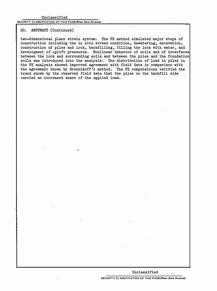
20. ABSTRACT (Continued)
two-dimensional plane strain system. The FE method simulated major steps of construction including the in situ stress condition, dewatering, excavation, construction of piles and lock, backfilling, filling the lock with water, and development of uplift pressures. Nonlinear behavior of soils and of interfaces between the lock and surrounding soils and between the piles and the foundation soils was introduced into the analysis. The distribution of load in piles in the FE analysis showed improved agreement with field data in comparison with the agreement shown by Hrennikoff's method. The FE computations verified the trend shown by the observed field data that the piles on the backfill side carried an increased share of the applied load.
Unclassified
SECURITY CLASSIFICATION OF THIS PAGE(When Dete Entered)
• I I
U3� �.$_7�-�
�.3
FOREWORD
The fi ni te e lement analys is of the pi le foundations of the Colum
bia Loc k was spons ore d by the U. S. Army Engi neer Dis trict, Vic ks burg
( VED), and was conduc ted by the Soils and Pavements Laboratory ( S&PL),
U. S. Army Engi neer Waterways Experiment Stati on ( WES), Vi cksburg,
Mis s i s s ippi .
The inves ti gati ons des cribed herei n were performed by Dr. c. S.
De sai and Dr. L. D. Johns on, Research Engineers , Soi l Mechanics Division
( SMD). Mr. C. M. Hargett, Engi neeri ng Divi s i on, VED, monitored the
project and provided valuable comme nts and advice. Mr. W. c.
Sherman, Jr. , Research Cons ultant, SMD, and Mr. S. J. Johns on, Special
As sistant to the Chief, S&PL, provided a technical review of the report.
The report was reviewed and approved by the Vicks burg Di strict prior to
publicati on. Mr. V. M. Agosti nelli , VED, provided useful c omments .
During the inve stigati on, Mr. J. P. Sale was Chief, S&PL; Mr. C . L.
McAnear was Chief, SMD.
Direc tors of WES during the analysi s and preparation and public a
ti on of thi s report were BG E. D. Pe ixotto, CE, and C OL G. H. Hilt, CE.
Mr. F. R. Brown was Technical Direc tor.
i i i 7D1D7
FOREWORD. •
NOTATION.
CONTENTS
. ·
CONVERSION FACTORS , BRITISH TO METRIC UNITS OF MEASUREMENT.
SUMMARY
PART I: INTRODUCTION •
PART II: DETAILS OF LOCK AND FOUNDATION SOILS.
Subsoils . Stress-Strain Parameters.
PART III : IDEALIZATION AS A TWO-DIMENS IONAL PROBLEM.
PART IV: FINITE ELEMENT ANALYSIS AND RESULTS • •
·Si mulati on of Cons truc ti on Sequences . Comparis ons •
Comments on Formulati on and Codes •
PART V: CONCLUS IONS AND RECOMMENDATIONS.
Conclus i ons •
Rec ommendati ons •
LITERATURE C ITED.
TABLES 1 and 2
v
Page
i i i
vii
i x
xi 1
2
2 2
11
15
15 15 25
26
26 27
28
NOTAT ION
A Projected area of pile
A . Equivalent area of piles battered inward ei A Equivalent area of piles batte red outward e o
c Mohr-Coulomb cohes ive strength paramete r
c Adhesi on a d Experimentally determined paramete r
D Depth of overburden
E Modulus of elasticity
E . Equivalent modulus of elasticity for piles battered inward e i
E Equivalent modulus of elastic ity for piles battered outward eo E. Initial modulus
1 E
t Tangent elastic modulus
F Experimentally determined paramet er
G Expe rimentally determined parameter
k. Initi al tangent s t i ffnes s 1
k Normal stiffnes s n k Res idual stiffnes s r
k5t Tangent shear stiffness
K Hype rbolic loading paramet er
Kj Experimentally determine d parameter for interface
l(C Coeffi cient of e arth pressure in compression 0
K Hyperboli c unloading parameter u L Length of piles
L . Equivalent length of piles batte re d inward €1
L Equivalent length of piles battered outward e o m Number of rows in a monolith
vi i
a -1
s
s
n
n. l.
n 0
Pa R
f
ei
eo s .
l. s
0 s
y Yw
0
\ >.2
\)
"f \)t O'l
0'3 O' n O' x O' y 0
3 l'
r/J
Experimentally determined parameter; also, total number of piles
Number of piles battered inward
Number of piles battered outward
Atmospheric pressure
Failure ratio
Equivalent stiffne ss per strip for
Equivalent stiffness per st rip for
piles battered
pi les battered
Sti ffness per strip for piles battered inward
Sti ffness per strip for pi les battered outward
Total axial stiffness
Unit wei ght
Unit weight of water
inward
outward
Angle of friction between lock or pile material and surrounding s oils
Parameter
Paramete·r
Poi s s on ' s rat i o
Poisson ' s ratio at fai lure -.
Tangent Poi s s on ' s ratio
Major principal stress
Confining pressure
Normal stress
Hori zontal stress
Vertical stress
St ress di fference
Shear_ stre s s
Mohr -Coulomb ( angle of internal friction ) parameter
vii i

CONVERSION FACTORS , BRITISH TO METRIC UNITS OF MEASUREMENT
British units of measurement used in thi s report can be converted to
metric units as follows:
Multi:El:z'.: B;y: To Obtain
feet 0 . 3048 meters
miles (U . S . statute ) 1 . 609344 kilometers
square feet 0 . 09290304 square meters
pounds per square foot 47 . 88026 pascals
pounds per cubic foot 16 . 01846 kilograms per cubic meter
tons 907 . 1847 kilograms
kips 4448 . 222 newtons
ix

SUMMARY
The Columbia Lock was designed as a gravity-type structure in which the load is trans ferred essentially through the foundation piles . Fi eld performance of the lock pile system was measured in terms o f settlements and·loads i n the piles . The structure was analyzed using Hrennikoff's method, which is based on a number of simplifying assumptions such as linear material behavior and linear distribution of loads in the pile groups . The obs ervations in terms of distribution of loads in the piles di d not show good correlation with the distribution predicted by Hrennikoff's method.
In order to evolve a more·rational procedure for design analysis and for improved understanding of behavior of the pile foundations , it was proposed to analyze the system using the finite element method . The method simulated major steps of the construction sequence including in situ stresses , dewatering , excavation , construction of piles and lock , backfilling , filling the lock with water , and development of uplift pressures . Nonlinear behavior of soils and of interfaces between the lock and surrounding soils and between piles and the foundation soils was introduced i�to the analys is .
For simplicity and to avoi d undue amounts of manpower and computer e fforts , the three-dimensional system was idealized as a structurally equivalent two-dimensional plane strain system.
The numerical results in terms of loads in the piles and settlements showed satis factory correlation with the observations . It is believed that the approximate two-dimens ional analysis can provide solutions of practical accuracy .
An available computer code which was developed for U-frame locks was modi fied to handle the gravity-t:y£e structures,_:Q_articularly_ the foundation piles and interfaces . Although the results were found to be satis factory , it seems that the code will need further modifications . Thi s will involve proper introduction of interfaces and their properties and a scheme that can avoid excess ive deformations of "air" elements that nee d to be introduced during various excavation and construction sequences . It appears that the existence of air elements renders the total stiffness matrix ill-conditioned and hence the excessive deformations . It may be possible to introduce a scheme such that the need for air elements is avoided in most computations . Moreover , the work can be continued further to analyze the interaction effects and the behavior of the structure itself.
xi
FINITE ELEMENT ANALYSIS OF THE COLUMBIA
LOCK PILE FOUNDATION SYSTEM
PART I : INTRODUCTION
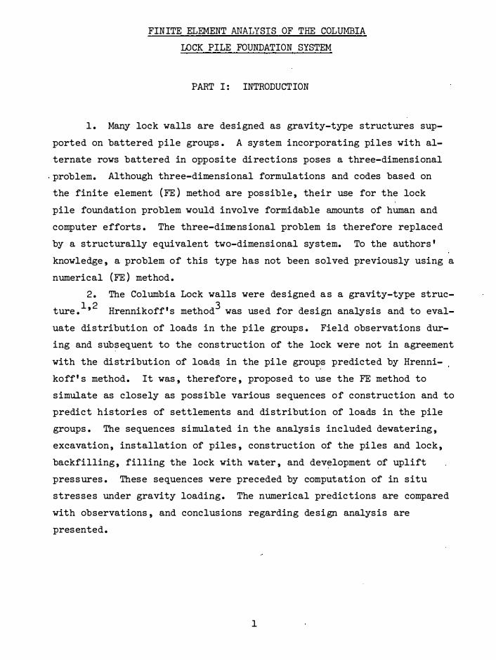
1 . Many lock walls are designed as gravity-type structures sup
ported on battered pile groups . A system incorporating piles with al
ternate rows battered in opposite directions poses a three-dimensional
.problem. Although three-dimensional formulations and codes based on
the finite element (FE) method are pos sible , their use for the lock
pile foundation problem would involve formidable amounts of human and
computer efforts . The three-dimens ional problem is therefore replaced
by a structurally equivalent two-dimensional system. To the authors'
knowledge , a problem of this type has not been solved previously using a
numerical (FE) method .
2 . The Columbia Lock walls were des igned a s a gravity-type struc
ture . 1'2 Hrennikoff's method3
was used for design analysis and to eval
uate distribution of loads in the pile groups . Field observations dur
ing and sub�equent to the construction of the lock were not in agreement
with the distribution of loads. in the pile groups predicted by Hrenni
koff' s method. It was , therefore , proposed to use the FE method to
simulate as closely as poss ible various sequences of construction and to
predict histories of settlements and distribution of loads in the pile
groups . The sequences simulated in the analys is included dewatering ,
excavation , installation of piles , construction of the piles and lock ,
backfilling , filling the lock with water , and development of uplift
pressures . These sequences were preceded by computation of in situ
stresses under gravity loading . The numerical predictions are compared
with observations , and conclusions regarding design analysis are
presented.
1

PART II : DETAILS OF LOCK AND FOUNDAT ION SOILS
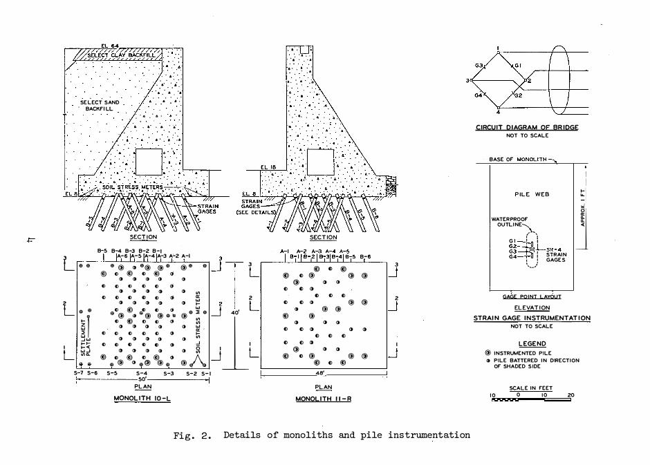
3. Columbia Lock is locate d in a cutoff between miles 131. 5* and
134. 5 on the Ouachita Rive r near Columbia, Loui siana. Fi g. 1 shows a
typi cal section through the lock chamber togethe r with foundati on and
surrounding s oils . 2'4
'5 Details of two monoliths ,·10-L and 11-R, that
were instrumented and are consi dered in the FE analysi s are shown in
fi g. 2. This figure als o shows details of the strain gages installed
on the steel H-piles . A plan of the lock and details of the instru
mented monoliths are shown in fi g. 3.
Subs oils
4. The subs oils beneath the lock cons ist ess entially of cohes ive
backswa.mp depos its and/or cohesi onless subst ratum dep osits beneath the
east wall and Te rtiary deposits interfingered with colluvium and sub
stratum depos its beneath the west wall, fig. 1.4
'6'7 The backswamp de
posits consist of sti ff to ve ry stiff fat clays and very s oft to medium
silty clays and silty s a�ds . Substratum depos its consist of dens e to
ve ry dense sands . The Tertiary soils can be divided into two part s .
The upper part, to e l -20 . 00, ** c onsists o f dense, gray, mas sive to
poorly be dded silts, silty s ands , and fine s ands with scattered hori zon
tal layers of stiff, gray, and grayi sh-brown clay. The lowe r portion i s
composed of thicker zones of sti ff, gray t o brown clay mi xe d with
thinne r layers of dens e to ve ry dens e, gray, fine , and s ilty s ands .
Stress -St rain Parameters
Soil behavior
5. Results from a number of triaxial tests performed previ ously
* A table of fact ors for converting British units of meas urement t o metric units i s presented on page ix.
** All elevati ons (el ) cited he rein are in fe et re ferred t o mean sea level.
2

J "' ,, I-w w IL �
LU z 2 I-< > Ill J Ill
90
60
40
20
-20
-40
-60
-eo
LOWER POOL EL 34
Fig. 1.
WEST WALL
UPPER POOL EL 52
RANDOM BACKFILL.
SANO BACKFILL
LOWER TERTIARY !STIFF CLAYS WITH VERY OENSE,SIL TY1 ANO FINE SAN OSI
Cross section and soil profile, Columbia Lock
90
60
40
J "' 20 ,, 1-w Ill IL
0 � z 2 I< > -20 � Ill
-40
-60
-60
SELECT SAND . BACKFILL
. . . a .
. . . . , • •:a.·
.. ·. A • • •
a. . � . ·a . . . . . .
. • ·
• • A • • 6 •
. . a . a· . A • ·6·
.. . · . . :.
SECT ION
B-5 B-4 B-3 B-2 B-1
L e e A-6 A-5 A-4 A-3 A-2 A-I
e@ IJ e@ @e @e <ll () @) @) () @) (j
I) I) I) I) I) () () {) () () (j
I) () I) I) () "' () () Cl () Cl (j a:
L I) I) () I) I) w I-
e e () @) () () " w
�r <ll@ <J e@ @ e"' @e:::;: e () © () () " "' "' I) I) () I) () w
() () a: . () () () I) I-...JW () () () I) I) "' 1-1- () () {) () I) I) ...J
I 1-< 0 L
W...J () () I) I) () "' If) a. © Cl @) C> @) I) @ A <ll <ll e@ <J e@ @ e
3
�T 3
L
2
L _J 40'
JlL S-7 S-6 S-5 S-4 S-3 S-2 S-1
50'
PLAN
MONOLITH 10-L
... . ..
. ... . . . · a . . ·.A
6 • . • • . . . •
.. ·.
• . . _..,,
. . ·.1.. : '. o.' •• 6 .
�
@) I> @) () @
@ () () () Cl () I> () () () ()
@)
() I) @ @
@) @ () () () I) I) ()
I) I) I) I) I) I)
@ () () @) () @
@) I) © 48'
PLAN
@
@
()
@
MONOLITH 11-R
B-6
3
@ _J
2 @ _J
() I
@ _J
Fig. 2. Details of monoliths and pile instrumentation
CIRCUIT DIAGRAM OF BRIDGE NOT TO SCALE
BASE Of MONOLITH--,.
PILE WEB 1 �I
WATERPROOF OUTLINE'\
( .. ,I G l =-4iJ I G2�LsR-4 g!=H" i STRAIN
J t J GAGES ..... _./
GAGE POINT LAYOUT
ELEVATION STRAIN GAGE INSTRUMENTATION
NOT TO SCALE
LEGEND @ INSTRUMENTED PILE
<I PILE BATTERED IN DIRECTION OF SHADED SIDE
SCALE IN FEET 10 0 �
10 20

Vl
"I -
5e-l/�m�rtl plaf� lype c - ___ .....,...,
l El-28.6 TB-13
2 j I B-/
TNo·ply neoµrene �· cooled f'IS'hr: fbbr1c
Cl 0\ "' � "' � .,,
Pi�z.o,,,el•r riser pipe�
�I ll:--....
�I ""
&11/emenf plole, lrjpe D
10 SCA!_[ t�' F"E"£T 16 zo
<> Cl' 0\ "'' "' "': � ,,/ �i /'(, z "' �
-I! � "' "'
/:J·R i!O·R Z ·R "' � .. " -11 "'
B·J
•o
Fig. 3. Details of instrumented monoliths
8·4
� l � 3 ..
tw�i:'"'"'-•0 ")Oc." "'"' "10.C.� Ci." 1'2.J ........ iD7
\."lov C.'T e"""'"( c;.&
l'l,Ji.IL'f '1 14 ""°""" (,,,1 8 M. ... -r <.&
a. .. a• P ... .,.,.. �
j.,,. e. �&3 AO.oco �8- '$&1
&-'l."'i& 59, 7S5 '"1B.l'"

on the Terti ary clays were available.1'2 For the FE analysis , the
stress-strain curves were simulated by us ing.the hyperbolic formulation .
Details of the hyperbolic formulation are given in various publica
tions 8-15 and are not repeated herein. According to this concept, the
tangent elastic modulus , Et
, and the tangent Poisson's ratio, vt
,
are given by
in which
G,
and
E. = 1 K =
a -1
pa a3
n
a3 F , and d
=
= =
=
=
initial modulus
hyperbolic loading parameter
atmospheric pressure
confining pressure
exponential parameter
stress difference
parameters determined from laboratory tests
·Rr(.01 - 03)(1 - sin �) Al
= 2c cos ¢ + 203 sin ¢
Here Rf = failure ratio and c and ¢ = Mohr-Coulomb strength
parameters .
( 1 )
( 2 )
(3)
6 . The hyperbolic parameters for other soils were adopted from
test data on similar soils reported in previous studies .B , 9 ,l5 Table 1
shows the hyperbolic parameters and other properties of soils adopted
6
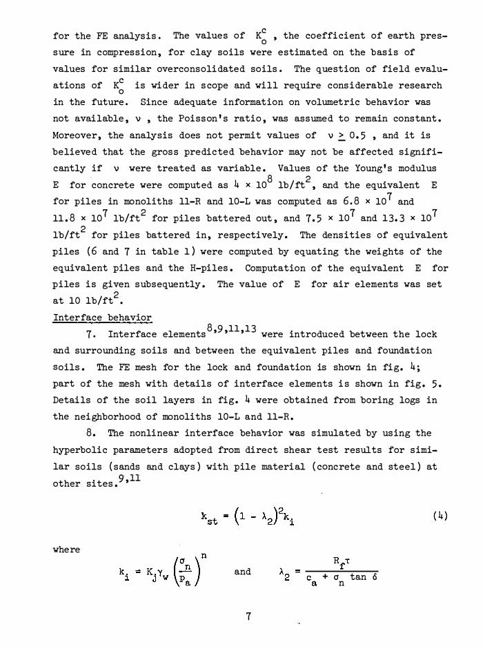
for the FE analysis. The values of Kc , the coefficient of earth preso sure in compression , for clay soils were estimated on the basis of
values for similar overconsoli dated soils. The question of field evalu
ations of Kc is wider in s cope and will require cons iderable research 0 in the future. Since adequate information on volumetric behavior was
not available , v , the Poisson's ratio , was assumed to remain constant .
Moreover, the analysis does not permit values of v � 0. 5 , and it is
believed that the gros s predicted behavior may not be affected signifi
cantly if v were treated as variable . Values of the Young's modulus . 8 2 E for concrete were computed as 4 x 10 lb/ft , and the equivalent E
for piles in monoliths 11-R and 10-L was computed as 6.8 x 10⁷ and
11 . 8 x 10⁷ lb/ft2 for piles battered out , and 7 . 5 x 10⁷ and 13. 3 x 10⁷
lb/ft2
for piles battered in , respectively. The densities of equivalent
piles ( 6 and 7 in table 1 ) were computed by equating the weights of the
equivalent piles and the H-piles . Computation of the equivalent E for
piles is given subsequently . The value of E for air elements was set
at 10 lb/ft2
•
Interface behavior
7. Interface elements8'9'11'13 were introduced between the lock
and surrounding soils and between the equivalent piles and foundation
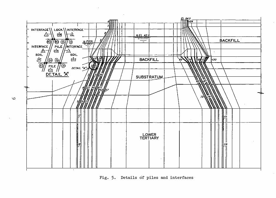
soils . The FE mesh for the lock and foundation is shown in fig. 4 ;
part of the mesh with details of interface elements i s shown in fig . 5 .
Details of the soil layers in fig . 4 were obtained from boring logs in
the neighborhood of monoliths 10-L and 11-R .
8 . The nonlinear interface behavior was simulated by using the
hyperbolic parameters adopted from direct shear test results for simi
lar soils ( sands and clays ) with pile material ( concrete and steel ) at
other sites . $r ,ll
where
and
7
+ a tan o n
( 4 )

RIVER SIDE I � .. b --
BACKSWAMP n o,,vv Fl ... ,, I
c EXf"Al/AT!Qt!...J..llil!;
SUBSTRATUM
LOWER TERTIARY
LEGEND
f::::. ELEMENTS Q NODES
y
�
-f l'-o•
9 9�@ /:j .............. . .... ........... . -----
.!.!!
II II
I 111/l//I II MON�ITH 'Til R..f' II 1111 1'
. �...-- 9� 1111 //#/.' "°
��/ /j////
i;:f//////t1T !.�Ill//! I
IP:•
U1-o•
I '7 FL"'" ---
I £L /110 '""-.o.n ...
Rt,�. ' \ \\\ \ \ ' 108-
I 11\\\\'\\ \ I iffi'll 1'\�\1 \ '-'"-\ \I 1/7/ ft�
\ \.\.\\.\ �-..... \ \\\\\ \ \
LANO SIDE
BACKFILL
Ii
�;� 00oln Ul'M8RAM"
I \ \\\\\ \ \
�:_tTPIL�� \ '
�
Fig. 4. Finite element mesh for lock and foundations
@ {71
.I\ m
EXCAVATI""' t INE I j BACKSWAMP
SUBSTRATUM
LOWER TERTIARY
!§!
e:!:_..
EL 42.0
BACKFILL
SUBSTRATUM
LOWER TERTIARY
Fig. 5. Details of piles and interfaces
BACKFILL.
115

and
kst = tangent shear stiffness
ki = initial stiffness
Yw = unit weight of water
cr = normal stress n -r = shear stress
c = adhesion a o = angle of friction between lock or pile material and sur
rounding soils
Kj , n , and Rf
are determined from test data. Hyperbolic parameters
for the interfaces are shown in the following tabulation . As soon as
the shear stress at the interfaces equalled or exceeded the Mohr-Coulomb
strength , the value of shear stiffness was set equal to the residual
stiffness , k ( see tabulation ). The normal sti ffness , k , was r 8 n assi gned a high value of 10 lb/ft
3 before failure and a small value
of 10 lb/ft3 after failure . Interfaces between the same material were
kept inoperational by ass i gning both kst 108 lb/ft3•
kr Kj Material lb/ft3 0 c a
12 10 33 0 7 . 5 x 10⁴ 13 10 26 0 2 . 5 x 10⁴
14 10 20 0 2 . 5 x 10⁴
10
and k very high values of n
n Rf Remarks
1.0 0.87 Lock backfill
1.0 0.87 Piles , sand substratum
1.0 0.87 Piles , Tertiary clay

PART III : IDEALIZATION AS A TWO-DIMENSIONAL PROBLEM
9. The three-dimensional Columbia lock pile foundation system
was idealized as a two-dimensional plane strain problem by making a num
ber of assumptions . Fig. 6 shows a schematic representation of a mono
lith with two types of piles , those battered inward and those battered
outward.
• BATTERED OUTWARD= n0
Q BATTERED INWARD= ni
j_ UNIT LENGTH
T
Fig . 6 . Schematic representation of monolith
10. Aspume that the major response of piles is provided by the
axial stiffness . The total axial sti ffness , S , of a monolith can be
expressed as
n A E S =I¥ =
j=l j
11
AE ( n. + n ) -1 o L ( 5 )
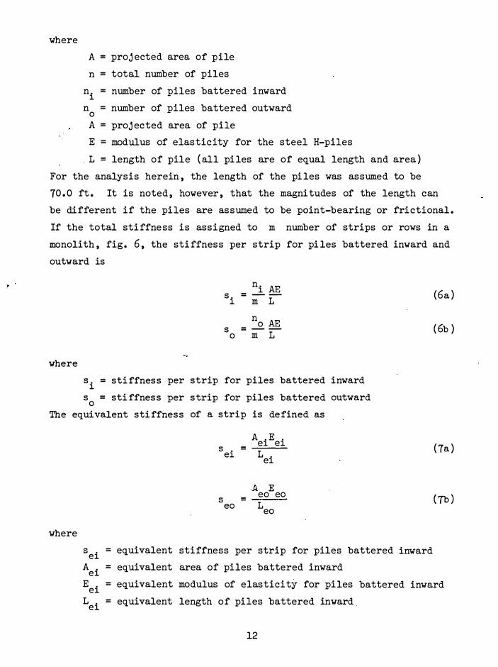
where
A = projected area of pile
n = total number of piles
n . = number of piles battered inward 1 n = number of piles battered outward 0
A = projected area of pile
E = modulus of elasticity for the steel H-piles
, L = length of pile ( all piles are of equal length and area )
For the analysis herein, the length of the pi les was assumed to be
70. 0 ft . It is noted, however, that the magnitudes of the length can
be different if the piles are assumed to be point-bearing or frictional .
If the total sti ffness is assigned to m number of strips or rows in a
monolith, fig . 6, the sti ffness per strip for pi les battered inward and
outward is
where
ni AE s. = - -1 m L
no AE s = --0 m L
s . = sti ffness per strip for piles battered inward 1 s = sti ffness per 0 strip for piles battered outward
The equivalent sti ffness of a strip is defined as
A . E ei ei s = ei L ei
A. E eo eo = s
eo L eo
where
s = equivalent stiffness per strip for piles battered ei A . = equivalent area of piles battered inward ei
(6a )
( 6b )
( 7a )
(7b)
inward
E = equivalent modulus of elasticity for piles battered inward ei L . = equivalent length of piles battered inward. ei
12

s = equivalent sti ffness per strip for piles battered outward eo A = equivalent area of piles battered outward eo E =
eo equivalent modulus of elasticity for piles battered outward
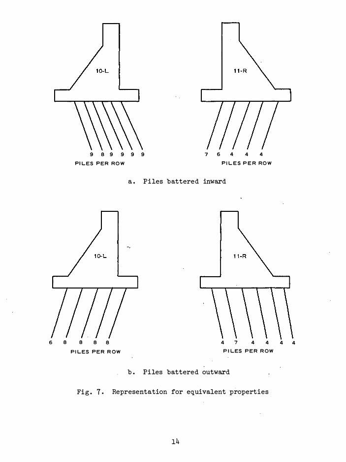
L = equivalent length of piles battered outward eo 11 . Two FE analyses were performed, one with piles battered out-
ward and one with piles battered inward ; and properties o f each were
evaluated . In both cases a unit width of strip was chosen for conve
nience , and equivalent properties for unit length were evaluated . The
following are the computations for the two cases , fig . 7a and b .
12 . The cross-sectional area of the H-pile used in the foundation
was 0 . 149 sq ft. 1'2 In the case of piles battered inward , there were
six rows of piles in monolith 10-L and five rows in monolith 11-R . For
monolith 10-L piles with inward batter, shown in fig . 7a, n. = 53 , 1 A = 0.149 sq ft·, E = 4 . 04 x 109 lb/ft2, m = 6 , A . = 1 x 40 ( unit ei width multiplied by length of the monolith) = 40 sq ft, and . L = L . • ei Therefore, equating equations 6a and 7a,
E . ei = 53 x 0 . 149 x 4 . 04 x 109 8 2
6 x 40 = 1 . 33 x 10 lb/ft
Similarly , for monolith 11-R piles with inward batter
E .
ei = 25 x 0 . 149 x 4 . o 4 x 109
= 7•5 x 10⁷ lb/ft2 5 x 4o
( 8a)
( 8b)
For piles with outward batter, fig. 7b, the equivalent moduli for mono-
liths 10-L and 11-R are, respectively :
E 38 x 0 . 149 x 4 . 04 x 109 1 . 18 108 lb/ft2 ( 9a) =
x 4o = x
eo 5
and
E 27 x 0 . 149 x 4 . 04 x 109 6 . 8 x 10 7 lb/ft2 ( 9b) =
6 x 40 =
eo
13
6 8
9 8 9 9 9 9 7 6 4 4 4 Pl LES PER ROW Pl LES PER ROW
8 8 8
a . Piles battered inward
4 7 4 4 PILES PER R OW P ILES PER R OW
b . Piles battered outward
Fig . 7 . Representation for equivalent properties
14
4 4

PART IV: FINITE ELEMENT ANALYSIS AND RESULTS
13 . Finite element analyses of U-frame locks were performed by
Clough and Duncan . 8 The computer code developed previous1y8 was uti
lized for the present analys is. However, a number of modifications and
corrections were introduced. The stresses in the interface elements
were made to be consi stent with those in the surrounding soil elements .
Modi fications were made to introduce interfaces and piles in the foun
dation such. that proper interfaces became operational as soon as the
buildup sequence was initiated. Similar changes were made for inter
faces that became operational as the structural buildup and backfill
proceeded .
Simulation of Construction Seguences
14 . The steps or cases in the simulation of construction se
quences are shown in table 2 . A cycle of the finite element procedure
was first performed to compute initial in situ stresses caused by the
gravity loading . Dewatering was then simulated to lower the water
table , which was followed by excavation in three steps . The materials
of elements oc cupying the locations of battered pi les were subsequently
changed from soil to steel piles with equivalent properties . The lock
structure was then constructed in three steps . Sequences 11 and 12
s imulated , respectively, the buildup of water in the lock up to el 42 . 0
and development of upli ft pressures . Upli ft pressures equal to the
hydrostatic pressure due to the waterhead in the lock were applied at
nodes at the bases of monoliths 10-L and 11-R and at the membrane ( see
fig . 4) . For each cycle , three iterations were performed and found to
be satisfactory for a convergent solution .
Comparisons
Settlements
15 . Fig . 8 shows a comparison between the predicted vertical
15

0
-0.1
-0.2
-0.3
-0.4
-o.s
0
I- -0.1
u.
� z -0.2 w � w .J I- -0.3 I-w II)
-0.4
-0.5
0
-0. 1
-0.2
-0.3
7 . -
\ �
9
OBSERVATIONS
FINITE ELEMENT � lO COMPUTATIONS :.,.._,r
� ......:-
10 0
10
11 0
'l
11
PLATE NO. 1
PLATE NO. 3
0 PLATE NO. 4
12
1� --
12
J F M A M J J A S O N D J F M A M J J A S O N D J F M A M J J A S O N D
1967 1968
NOTE: N UMBERS INDICATE FE SEQUENCES (TABLE 2)
Fig . 8 . Comparisons between predicted and observed set�lements, monolith 10-L
1969
displacements measured at nodes near typical settlement plates in the
backfill adjacent to monolith 10-L ( fig. 3) and the observed settlements
of the plates . The FE results are shown for four stages : completion
of lock wall construction, completion of backfill, filling the lock, and
after the application of uplift pressures . The correlation between
16

observations and predictions is cons idered to be satis factory . The ob
servations showed that after water was introduced into the lock , the
settlements (up to 1972) remained essentially the same or decreased in
magnitude . The decrease may be due to the effect of upli ft pressures .
The FE computations with full upli ft pres sure also showed a decrease in
predicted settlements .
16 . In fig . 9a are shown observed and computed displacements at
various locations in the backfill side that took place between the
period 14 August 1968 ( end o f backfilling) to 1 January 1972 (during
operations) . The comparisons for plate 2 ( fig. 3) below the heel of
the monolith are not shown for clarity ; the computed settlement of
this plate was about -0 . 04 ft whereas the observed value was on the
order of -0 . 0 55 ft. Although the FE computations do not provide exact
simulation of natural and man-made conditions , the computed vertical
displacements at typical nodes in the backfill for a short portion ,
from completion of the backfill (August 1968) to filling the lock
(November 1968) , of the foregoing period seem to follow the trends of
the observations and are of the same order of magnitude , fig . 9a . These
nodes are in the neighborhood of the locations of the corresponding
settlement plates in the backfill , fig . 3. 17 . Fig . 9b shows computed vertical displacement patterns for
various stages of construction at two sections :
structure and at section B-B in the foundation .
at the bas·e of the
Dewatering ( stage 1)
showed settlements whereas at the end of excav.ation ( stage 4) , the
highest rebound occurred . Subsequently the foundation showed settle
ments as the construction proceeded. After the structure was com
pleted , the distribution of displacements was es sentially symmetrical .
At the end of backfill ( stage 10) , the foundation zone below monolith
10-L settled more than the zone below monolith 11-R because the backfill
was provided only behind monolith 10-L . Under the upli ft.pres sures
(stage 12) , the foundation settlements showed a decrease . The final
settlements are , however , less than the total rebound after excavation .
This seems reasonable since the approximate weight of material exca
vated was about 57 ,000 tons whereas the total applied load , including
17

DISTANCE, fT fROM CENTER LINE Of LOCK 90 80 70 60 ' 50 '10 30 zo 10 0 10 20 30 '10 50 60 70 80 90 100
�-
�--
t- _] ... .... -z "' ::; "' u <
47
..J
_] .. "' 0 4J
I�
Fig. 9.
[]
12; I
,,�
10\ CT
,,7
10, T-.,
117
�
I I I
I I I
I I I
SECTION A-A
SECTION B-8
, ,:;;;
:�
b. COMPUTED SETTLEMENTS AT VARIOUS STAGES
D
\4
I�; cT 12\
I
616 630
-o.os '---- - --- _ _. o c r--·c:J ]-:.05
-0.10 618 632 . o[ •---------, I
4L = ·1T o -0.05 . ..__ - lo.OS
��2
,/10
'"
� --- fE COMPUTATIONS FROM STAGE 10-11 -- OBSERVATIONS FROM AUG 68-JAN 7Z
e NODES O SETTLEMENT PLATE
6 636 •
"1.<r-_--�-----------=--= J 0 ---® L. ---- - - - -0.05 •
----® ci. COMPARISON OF SETTLEMENTS
IN BACKFILL
� Comparisons of settlements in backfill and computed settlement of foundation
(for construction sequences, see table 2)

the structure, backfill, and water, was about 35, 000 tons . The weight
of the excavated material and backfill in these computations includes
the entire area that was affected by excavation and backfill, as shown
in the FE mesh, fig . 4 .
18 . Computed vertical settlements at nodes 199 and 483, fig. 9,
beneath monoliths 11-R and 10-1, respectively, are shown in fig . 10 .
The average observed vertical displacements of settlement plates 1 and
2, monolith 10-1, fig. 3, after completion of lock construction and
backfill shown in fig . 10 compare favorably with the corresponding FE
results, sequences 1 and 10 in table 2. The displacements under both
monoliths are about the same up to the end of lock buildup ( stage 7),
with monolith 10-1 showing somewhat larger displacements . This may be
� LL
..: z w ::E w u c( _J a. � 0
DEWATER/NG
WATER 0.6 LOCK BACKFILL IN
EXCAVATION CONSTRUCTION PLACED
� UPLIFT
PRESSURE
0.4
0.2 ' NODE 199 BENE A TH 11-R � ®
' '
0 @ OBSERVED A VERAGES FOR 10-L � /-ME ASURED WITH RESPECT TO ......... "'Cl POIN T A
2 4 6 B 10
CONSTRUCT! ON SEQUENCE
Fig. 10 . Settlement versus construction sequences at typical nodes, 199 and 483, fig . 9
19
12

due to the fact that the soil beneath 10-L contains a greater depth of
relatively weaker Tertiary clay as compared with the depth of substratum
sands, fig . 4, than does the soil beneath 11-R . Monolith 10-L shows
significantly larger displacements after the backfill behind 10-L is
completed .
Loads in piles
19 . Typical results for piles battered out (B piles) and battered
in (A piles) are shown in fig . 11 . Distributions of loads along each
of the instrumented rows as computed by Hrennikoff's method3 are also
shown in fig . 11 .
20 . An approximate value of load in a pile was obtained on the
basis of the computed vertical stress in the element at the butt of
the pile . This stres s was multiplied by the width ( 1 ft) o f the equiva
lent pile and length ( 40 ft) of the monolith ( fig. 6), and the product
was divided by the number of piles in the row along the length.
21 . As shown in fig . 11, the measurements were recorded at vari
ous times after the structure was completed . In some cases, measure
ments for only one pile location were available . The computed distribu
tions of loads are in good agreement with the measured di stributions for
the cases where sufficient data were available . The measurements showed
that the outer row carried hi gher loads than the pi les in the center .
This observation is cons istent with previous reports for friction pile 4 5 16 groups . ' ' The predictions for the completion of backfill, particu-
larly for monolith 10-L, fig. llb, also support this observation .
22 . The distributions of loads given by Hrennikoff's method are
always linear and do not in general agree with the observations . This
may be due to the fact that Hrennikoff's method does not account for
nonlinear behavior of soils and interfaces and the interaction behavior
of the system.
23. Fig . 12a shows computed distributions of stresses in the
piles under monoliths 10-L and 11-R for the case of piles battered out .
As expected, the piles on the backfill side show higher stresses than
the piles below monolith 11-R . The stresses increase in magnitude up
20

A- 1 A-2 A-3 A-4 A-5
100
200
I/) 300 a.. :;: PILES BATTERED IN ri < 0 8-5 8-4 8-3 8-2 8- 1 8-1 8-2 8-3 8-4 8-5
..J 0
PILES BATTERED OUT MONOLITH 10-L MONOLITH 11-R
a. END OF LOCK CONSTRUCTION-NO BACKFILL <CASE 7)
A-6 A-5 A-4 A-3 A-2 A- 1
1 00
200
� 300 ...._ ________________ _
A-1 A-2 A-3 A-4 A-5
yMAR 1971 _ -
�
� 0
PILES BATTERED IN
< 8-3 8-2 8-1 0 8-5 8-4
..J 0-----------...----.---....----.
1 00 --
200
--- - ---·--- --
8- 1 8-2 8-3 8-4
PILES BATTERED OUT MONOLITH 10-L MONOLITH 11-R
b. BACKFILL COMPLETE (CASE 10)
LEGEND e MEASURED
0 F.INITE ELEMENT SOLUTION
--- HRENNIKOFF'S METHOD
8-6
Fi g . 11. Comparison between computations and field observations of distribution of loads in piles

I\) I\)
90 80 70 60 .50
RIVER SIDE
Jr __
0� /0 7 9�7 20 000 �:::;r-.:;:
• ---J 12 vi'
40,000 , __ .,. a. STRESSES IN PILE BUTT
... .. ' m 0 ...j
J ui 2,000 "' ... a: ... .,
... ooo
8,000
DISTANCE, FT FROM CENTER LINE OF LOCK
.. 0 30 20 10 0 10 20 30
�
I . I I
I LOCK SLAB
.. ... .. '
0
� 1,000
if � ... 2,000 ... " ... Ill
7)_ ���� ----;;;:g
"'�........ ... ____ - ... --.. ___ ,_q'L
"'-'---12-._---
-
---
-----
---- -
------::::----'"
3,ooo �-----------------c. SOIL STRESSES BELOW LOCK SL AB
SECTION A-A
e,ooo�--------------------------------b. SOIL STRESSES
SECTION B-B
.. o
.. ... .. ' m ...j
b;:. "' "' ... " ... .,
.50 60 TO
0
7 9 Z0,000 (°r-��
��---\>� /' � ,'t2 40,000 � .. �10
. . __, �;::z,, 60,000
80 90 100
LAND SIDE
----4 � CONDITION
7 ENO OF LOCK CONSTRUCTION
DURING BACKFILL
I 0 BACKFILL COMPLETE
I I WATER IN LOCK
I 2 UPLIFT PRESSURE
a. STRESSES IN PILE BUTT
Fig. 12. Computed stress d istributions in piles, foundation, and below slab

to sequence 11, water in the lock ; thereafter, under uplift pres sure,
the stresses in the piles decrease .
Soil pressures
24 . Computed distributions of vertical soil stresses in the ele
ments at section B-B in the foundation for typical sequences are shown
in fig . 12b . The soil stresses are higher under monolith 10-L, and
they increase in magnitude up to sequence 11 . Under upli ft pressure,
the soil stres ses decrease in magnitude .
25 . Computed distributions of vertical soil stres ses in the ele
ments immediately below the slab of the lock are shown in fig . 12c .
Lateral pressure in backfill
26 . Computed distributions of the vertical and horizontal
stres ses in the elements along the section Y-Y in the backfill region
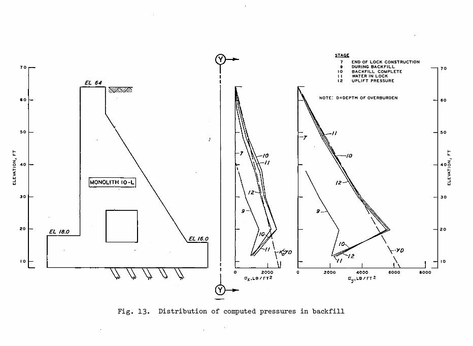
are shown in fig . 13. The vertical stresses follow es sentially the
linear variation, o = yD , for a major portion o f the depth, where y o = vertical stress , y = unit weight of backfill , and D = depth of y overburden • In the lower portion, however, the pressure shows a
significant decrease as compared with the linear distribut ion. One of
the reasons for such a reduct ion can be the existence of arching near
the base of the wall . The magnitudes of o decrease by small amount s y from sequence 10 to 12 in the upper zones, but ·increase by small amounts
in the lower zone • .
27. The horizontal stress, o , also decreases by somewhat x larger amounts from sequence 10 to 12 in the upper zones at constant
elevation, and increases by small amounts in the lower zone . For the . c major portion of the upper zone, the linear distribution, o = K yD x 0 '
where Kc = coefficient of lateral earth pres sure for the backfill 0
(o . 45 } , lies in the vicinity of the computed dis tributions .
Drag forces
28 . Di fferential settlement between the backfill and the lock
can cause drag forces which can increase loading on the foundation. 4
The drag forces were computed from the FE results by summing the shear
forces induced in the elements along the section Y-Y , fig . 13, adjacent
to the heel of the monolith 10-L . The net value of such drag forces
23
70
60
50
.... ... z· � 40 � � "' _J "'
30
20 EL 18.0
10
EL 64
� 7 END OF LOCK CONSiRUCTION
9 DURING BACKFILL 10 BACKFILL COMPLETE
I I WATER IN LOCK
12 UPLIFT PRESSURE
NOTE: D=DEPTH OF OVERBURDEN
'MONOLITH 10-LI
D EL 16.0
Fig. 13. Distribution of computed pressures in backfill
!>000 8000
70
60
50
� ... z
400
30
20
10
� "' _J "'
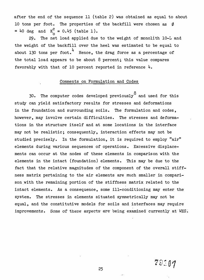
after the end of the sequence 11 ( table 2) was obtained as equal to about
10 tons per foot . The properties of the backfill were chosen as ¢ = 40 deg and Kc = o.45 ( table 1) . 0
29. The net load applied due to the weight of monolith 10-L and
the weight of the backfill over the heel was estimated to be equal to 4 about 130 tons per foot . Hence, the drag force as a percentage of
the total load appears to be about 8 percent ; this value compares
favorably with that of 10 percent reported in reference 4.
Comments on Formulation and Codes
30 . The computer codes developed previously8 and used for this
study can yield satis factory res ults for stres ses and deformations
in the foundation and surrounding soils . The formulation and codes,
however, may involve certain di fficulties. The stresses and deforma
tions in the structure itself and at some locations in the interface
may not be realistic ; consequently, interaction effects may not be
studied precisely . In the formulation, it is required to employ "air"
elements during various sequences of operations . Excess ive displace
ments can occur at the nodes of these elements in comparis on with the
elements in the intact ( foundation) elements . This may be due to the
fact that the relative magnitudes of the component of the overall stiff
ness matrix pertaining to the air elements are much smaller in compari
son.with the remaining porti on of the stiffness matrix related to the
intact elements . As a consequence, some ill-conditioning may enter the
system. The stresses in elements situated symmetrically may not be
equal, and the constitutive models for soils and interfaces may require
improvements-. Some of- thes-e as-p-ects- are- heing· examined - currently at- WES�
25 ,, ;) � o· 1 Ii \,; ... _,

PART V: CONC LUS IONS AND REC OMMENDATIONS
Conclus ions
31. The three-dimensi onal lock pile foundation system for the
gravity-type Columbia Lock was i deali zed as a two-dimensional problem.
The s ystem was simulated by an equivalent plane -strain idealization in
which a row of H-piles in the group was repres ented by a s �rip of unit
wi dth and length with equivalent ( axial ) sti ffnes s properties. The se
quences of const ructi on--in s itu stres s es , dewatering, excavation, con
struction of piles . and lock, backfilling, filling the lock with water,
and upli ft pressure--were simulate d i n the inc remental FE analys i s .
Nonlinear de formation characteristics of soils and interfaces were de
rived from laboratory triaxial and di re ct shear test s , respectively,
and were introduced into the FE procedure .
32. Even with the foregoing ideali zation to a two -dimensi onal
s ystem and approximations to the soil and interface parameters , the
predi cted behavior in terms of progress ive settlements and di stribu
tions of loads in the piles showed satis factory correlation with
corre sponding observations . The distribution o f loads i n the piles
from the conventional Hrennikoff ' s method did not show good agreement
with the pattern o f load di stributi ons , whereas the FE method showed,
in general, improved correlations . It should be noted that the loading
conditions and material properties as sumed in the design with Hrenni
koff1s method may be di fferent from those simulated in the FE analys i s .
The comparison herein is made only as a qualitative trend.
33. The concept of substituting for the th ree-dimens ional s ystem
-an -equival-ent-two--dimens ional -system for the FE analys is s eems t o be
satis factory from a practi c al viewpoint . It shows the engineer that
satis factory p re di cti ons c an be obtained b y us ing this ideali zation
which can provide signi ficant savings in terms o f human and computa
tional e fforts. The FE method can provide useful ins ight into and in
creas ed understanding of the behavior of battered pile groups for
26
• j
foundations of gravity-type structures , and can be used as a tool in
analysis and design .
Recommendations
34 . The investigation reported herein was directed essentially
to the study of stres ses and deformations in the foundation soils . As
remarked earlier , the present formulation and code may show local errors,
and the preciseness of interface stres ses may not be satis factory . It
is proposed that the formulation and code be examined thoroughly and that
poss ible improvements be introduced. The mathematical properties of
the interface element may require close s crutiny .
35 . The interaction effects between the structure and soils are
highly relevant from viewpoints of the design engineer . With the fore
going suggestion in paragraph 34, it will be very useful to adopt
finer meshes for the structure and compute detailed distribution of
stresses in the concrete structure . This will permit computation of
bending moments and shear forces at criti cal locations . A comparison
of such design quantities with the corresponding quantities based on
conventional methods can be relevant.
36 . The topic of group effects in pile groups is of importance
from the viewpoint of des i gn analysis . It is proposed that the finite
element procedure be extended and used to examine the group effects
and distributi on of loads in the piles in a group and the results com
pared with the loading capacity of such single piles .
37 . A parametric study to examine effects of such factors as
different values of K� , drained and undrained parameters , various
mesh layouts ,_ and interfaces at the base should be_ perfumed_ to_ as_sis_t_
the user in the proper choice of these quantities . Moreover , it is
pos sible to perform trial-and-error analyses in which both the
Hrennikoff ' s and FE methods are used under various combinations of
such factors as material properties , loadings , and geometry. These
can lead to better criteria for design analys is of gravity locks .
27
LITERATURE C ITED
1. U . s . Army Engineer Di st rict, Vicksburg, "Columbia Lock, Pile Tests --Lock Sit e , " Des ign Memorandum No. 6, Supplement No. 2, Dec 196 3, Vicksb urg, Mis s .
2. , "Columbia Lock, Mas onry and Embedded Metals , " Des i gn Memorandum No. 6, Mar 1963, Vi cksb urg, Mi s s .
3. Hrennikoff, A. , "Analysis of Pile Foundat ions with Batter Piles , " Trans acti ons , American Society of Civi l Enginee rs , Vol 115 , Paper No. 2401, 19 50, pp 35 1-381.
4. Montgomery, R. L. and Sullivan , A. L. , Jr. , " Interim Analysis of Data from Instrument ation Program, Columbia Lock, " Miscellaneous Paper S-72-30, Aug 1972, U. S. Army Engineer Waterways Expe riment Stati on, CE , Vicksb urg, Mi s s .
5 . Sherman, w . c. , Jr. , " The Behavi or of Lock Walls Supported on Batter Piles , " Proceedings , 8th International Conference on Soil Mechanics and Foundati on Engineering, Moscow, Oct 19 73.
6. Worth, N. L. et al. , "Pile Tests , Columbia Lock and Dam, Ouachita and Black Rivers , Arkansas and Louis iana, " Techni cal Report 3-741, Sep 1966, U. S. Army Engineer Waterways Expe riment Station, CE, Vicksburg, Mis s .
7 . U . S . Army Engineer Dis t rict, Vicksburg, " Ouachita-Black Rivers Navigati on Project, Ouachita River, Loui s i ana, Columbia Lock and Dam, " Peri odic Inspection Report No. 1, Oct 1972, Vicksburg, Mi s s .
8. C lough, G. W. and Duncan, J.·
M. , "Finite Element Analyses o f Port Allen and Old River Locks , " Cont ract Report S-69-6, Sep 1969 , U. s . · Army Enginee r Waterways Experiment Stati on, CE, Vicksburg, Mi ss . ; p repared unde r Contract No. DACW39-68-C-0040 by Lowe r Mis s i s s ipp� Valley Divi s i on, Vicksburg, Mis s .
· 9 . Desai, C . s . , "Finite Element Method for Des i gn ·Analysis of Deep
Pile Foundations " ( in preparation ) , U. S. Army Engineer Waterways Experiment Stati on, CE, Vicksb urg, Mi s s .
10. , "Nonlinear Analyses Us ing Spline Funct i ons , " Journal , Soi l Mechanics and Foundati ons Divi s i on Ame rican Societ of Civil Engineers , Vol 97, No. SMlO , Oct 1971, pp 1 61-1480.
11. , "Numerical Des ign Analysis for Piles in Sands , " sub-mitted to be published in Journal , Soi l Mechanic s and Foundati ons Division , Ame ric an Society of Civil Engineers .
12. Desai, C . S . and Abel, J . F. , Introduction to the Finite Element Method, Van Nost rand Reinhold Co. , New York, 1972.
13. Desai, C. S. and Holloway, D. M. , " Load-De formati on Analysis of Deep Pile Foundati.ons , " Proceedings 2 Symposium on Applic ati ons of the Finite Element Method in Geotechnical Engineering, C. s. Desai , ed. , Sep 1972, p p 629-656.
28
14 . Duncan , J . M. and Chang , C . Y. , "Nonlinear Analysis of Stres s and Strain in Soils , " Journal , Soi l Mechanics and Foundations Division, American Soci ety of Civil Engineers , Vol 96 , No . SM5 , Sep 1970 , pp 1629-165 3 .
15 . Kulhawy , F . H. , Duncan , J . M. , and See d , H . B . , "Finite Element Analyses of Stresses in Movements in Embankments During Construction , " Contract Report S-69-8 , Nov 1969 , U. S . Army Engineer Waterways Experiment Station , CE , Vicksburg , Miss . ; prepared under Contract No . DACW39-68-C-0078 , by Soil Mechani cs and Bituminous Materials Laboratory , University of Cali fornia , Office of Research Services , Berkeley , Cali f . , Report No . TE-69-4 .
lq . Chellis , R . D . , Pile Foundations , 2d ed. , McGraw-Hill , New York , 1961 .
29

Table 1
H;Q2erbolic Parameters and ProEerties for Di fferent Materials
Material* "f lb/ ft3 Rf Kc L \) x 0 c
1
2
3
4 5
6
7
8 9
10
11
Note :
0. 10 0. 10
0. 30 o . 48 120. 0 0. 90
0. 30 o . 48 58. 0 0. 90
0. 30 o . 48 53. 0 0. 85
0. 30 o . 48 58. 0 0. 85
0. 28 0. 28 61. 0 1. 00
0. 28 0. 28 66. o 1. 00
0. 10 0. 10 o . o 0. 20 0. 20 15 0. 0
0. 30 o . 48 115. 0 0. 85
6 . 48 o . 48 62. 4 1. 00
v = Poi sson ' s ratio.
"f = Poisson ' s ratio at failure .
y = unit weight.
Rf = failure ratio .
0. 70 26 0
0. 10 26 0
o . 45 4o 0
1. 10 30 0
1. 00
1. 00
1. 00
o . 45 40 0
1. 00
J(C = coeffi cient of earth pressure in compres s ion . 0
K K u
1000 2000
1000 2000
1160 175 0
400 Boo
5 8 0 860
¢ = Mohr-Coulomb ( angle of internal friction ) parameter.
c = Mohr-Coulomb cohesive strength parameter.
K = hyperbolic loading parameter .
K = hyperboli c unloading parameter. u n = experimentally determined parameter .
* Material Identification
1 Air 2 Backswamp clay above water table 3 Backswamp clay below water table 4 Substratum sand 5 Terti ary clay 6 Equivalent piles - 11-R 7 Equivalent piles - 10-L 8 Air as replacement 9 Concrete
10 Backfill s and 11 Water
n
o . o o . o o . o 0. 5
0. 5
o . o
0. 5
o . o
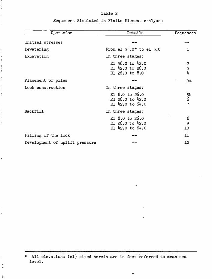
Table 2
Sequences Simulated in Finite Element Analyses
Operation
Initial stresses
Dewatering
Excavation
Placement of piles
Lock construction
Backfill
Filling of the lock
Development of upli ft pres sure
Details
From el 34 . 0 * to el 5 . 0
In three stages :
El 58 . 0 to 42 . 0 El 42 . 0 to 26 .0 El 26 . 0 to 8 . 0
In three stages :
El 8 . o to 26 . 0 E l 26 . 0 t o 42 . 0 El 42 . 0 t o 64 . o
In three stages :
El 8 . o to 26 . 0 El 26 . 0 t o 42 . 0 El 42 . 0 to 64 . o
Sequences
1
2 3 4
5a
5b 6 7
8 9
10
11
12
* All elevations ( el ) cited herein are in feet referred to mean sea level .