Embed Size (px)
Citation preview

This document contains the draft version of the following paper:
A. Ananthanarayanan, L. Ehrlich, J.P. Desai, and S.K. Gupta. Design of revolute joints for in-
mold assembly using insert molding. ASME Journal of Mechanical Design,
133(12):121010, Dec 2011.
Readers are encouraged to get the official version from the journal’s web site or by contacting
Dr. S.K. Gupta ([email protected]).

Design of Revolute Joints for In-Mold Assemblyusing Insert Molding
Arvind AnanthanarayananBiomimetics Robotics Lab
Massachussetts Institute of TechnologyCambridge, MA 02140
Email: [email protected]
Leicester EhrlichAdvanced Manufacturing Lab
Department of Mechanical EngineeringUniversity of Maryland, College Park
College Park, Maryland 20742Email: [email protected]
Jaydev P. DesaiRobotics, Automation,
and Medical Systems LaboratoryDepartment of Mechanical Engineering
University of Maryland, College ParkCollege Park, Maryland 20742
Email: [email protected]
Satyandra K. Gupta∗
Advanced Manufacturing LabDepartment of Mechanical Engineeringand the Institute for Systems ResearchUniversity of Maryland, College Park
College Park, Maryland, [email protected]
Creating highly articulated miniature structures requires as-sembling a large number of small parts. This is a very chal-lenging task and increases cost of mechanical assemblies. In-sert molding presents the possibility of creating a highly artic-ulated structure in a single molding step. This can be accom-plished by placing multiple metallic bearings in the mold andinjecting plastic on top of them. In theory, this idea can gener-ate a multi degree of freedom structures in just one processingstep without requiring any post molding assembly operations.However, the polymer material has a tendency to shrink ontop of the metal bearings and hence jam the joints. Hence,until now insert molding has not been used to create articu-lated structures. This paper presents a theoretical model forestimating the extent of joint jamming that occurs due to theshrinkage of the polymer on top of the metal bearings. Thelevel of joint jamming is seen as the effective torque neededto overcome the friction in the revolute joints formed by in-sert molding. We then use this model to select the optimumdesign parameters which can be used to fabricate functional,highly articulating assemblies while meeting manufacturingconstraints. Our analysis shows that the strength of weld-linesformed during the in-mold assembly process play a significantrole in determining the minimum joint dimensions necessaryfor fabricating functional revolute joints. We have used themodels and methods described in this paper to successfullyfabricate the structure for a minimally invasive medical robotprototype with potential applications in neurosurgery. Tothebest of our knowledge this is first demonstration of buildingan articulated structure with multiple degrees of freedom us-ing insert molding.
∗Address all correspondence to this author.
1 INTRODUCTIONCurrent methods to manufacture highly articulating me-
chanical assemblies involve fabrication of individual parts us-ing machining or rapid prototyping among other processes.Subsequently, these parts are assembled manually using me-chanical fasteners. These methods, although highly inefficient,are popular processes for making macro scale mechanical as-semblies. However, for fabricating miniature mechanical as-semblies (joint dimensions< 1 mm) [1], manual assembly op-erations become very tedious and, in some cases infeasible.This is because, owing to the individual part sizes, it is diffi-cult for a skilled human operator to assemble the parts. Alsofasteners are usually unavailable or are very expensive at thesmaller scale. Also, a mechanical assembly consisting of ahigh overall part count would be more susceptible to failure.Traditional machining and prototyping methods are thereforenot suitable for fabricating miniature mechanical assemblies.There is currently no scalable and cost effective manufacturingprocess that can be used to fabricate such miniature assembliesfor large scale production. There is therefore an impendingneed to develop new strategies for fabricating multifunctional,miniature mechanical assemblies.
Insert molding presents an efficient method of function-ally grading the fabricated structure according to the applica-tion. The process involves molding over a pre-existing moldinsert in the mold cavity. Popular molding processes for insertmolding involve injection molding and resin transfer molding(RTM). Insert molding has become a popular process for sev-eral applications such as composite fabrication [2], packag-ing [3], microfluidics [4] etc.
Researchers have studied insert molding of metals in

polymers in several applications over the past few years [5,6].They have developed methods for using metals as reinforcingstructures in injection molded polymer parts. Hence the focusof the research is on developing good bonding between thepolymer and the metallic structures. This is usually accom-plished by controlling the shrinkage of the polymer on top ofthe insert. However, these methods are not suitable for devel-oping articulating structures for miniature mechanical assem-blies. Hence, we need to develop methods to prevent bondingbetween the polymer and the metal inserts to allow for artic-ulation after the insert molding process. This paper will ad-dress this challenge and demonstrate an innovative manufac-turing approach based on the in-mold assembly process [7–9]to realize highly articulating mechanical assemblies. We willalso present an analytical modeling based approach to selectthe optimum joint parameters which enable effective use ofthis process. Finally we will demonstrate the capability ofthisprocess by using it to fabricate a multiple degree of freedomrobot structure with potential applications in minimally inva-sive surgery.
2 BACKGROUND: IN-MOLD ASSEMBLY
Fig. 1: MOLD DESIGN SOLUTIONS FOR REALIZ-ING MESOSCALE IN-MOLD ASSEMBLED REVOLUTEJOINTS [8,10].
In-mold assembly provides an effective alternate methodfor manufacturing miniature mechanical assemblies. Thesemethods have been developed in the past for both macroscale[7] and mesoscale [8,9]. Using this method, a fully assembledarticulating rigid body joint could be ejected from the mold.This eliminates the need for any post processing in the form ofadditional assembly steps, after the injection molding processwas complete. This process significantly reduces the overalllead time for production and also substantially reduces pro-duction costs. The in-mold assembly process is ideal for largescale production of miniature mechanical assemblies
Macroscale in-mold assembly methods involve injectinga second stage polymer over a premolded component whichcontains a hole. The second stage polymer fills the hole in thepremolded component. On controlling adhesion and shrinkageof the second stage polymer, in-mold assembled macroscalejoints with appropriate clearance can be manufactured.
However Ananthanarayanan et al. [10] have demonstratedthat this molding sequence does not work for the mesoscaledue to mold piece alignment issues. Hence, they have pro-posed a reversed molding sequence for realizing in-mold as-sembly at the mesoscale. This is illustrated in Figure 1. Usingthis molding sequence ensures that the mesoscale premoldedcomponents do not deform plastically during the second stageinjection.
At the macroscale, the joint clearance is realized due toshrinkage. After cooling, the pin, which is made of an in-jection molded polymer shrinks away from the hole [7]. Bycontrolling the injection molding parameters, it is possible toobtain appropriate friction in the in-mold assembled revolutejoint at the macroscale [11]. However, the reversed moldingsequence at the mesoscale may lead to jammed joints due toshrinkage of the polymer. This concept is illustrated in Fig-ure 2.
Fig. 2: CLEARANCES IN IN-MOLD ASSEMBLEDMACROSCALE REVOLUTE JOINTS [9]
To explain the issue of the jammed joints, Anantha-narayanan et al. [9] have reported a change in final pin diam-eter due to the second stage injection molding process. Thisis illustrated in Figure 3. The forces applied by the secondstage polymer melt during the packing phase causes the pin todeform plastically and reduce in diameter. This deformation

which is caused by the small size scales of the pin is instru-mental in relaxing the radial stresses at the interface of thejoint which are caused by the shrinkage of the cavity on thetop of the pin. The plastic deformation of the pin, if controlledeffectively, can be used as a method of controlling the finalclearances in the revolute joint. Hence, although the strategyof molding the cavity over the pin is counterintuitive from theshrinkage point of view, it works at the mesoscale due to theplastic deformation of the pin.
Fig. 3: MOLD DESIGN STRATEGY FOR CREAT-ING MESOSCALE IN-MOLD ASSEMBLED REVOLUTEJOINTS [9]
Current in-mold assembly methods require the use of cav-ity morphing methods. These molds require use of specializedinjection molding machines (rotary platen injection moldingmachines) consisting of multiple nozzles to inject differentmaterials sequentially into the mold cavity. Also, currentin-mold assembly methods require the use of multiple polymerswhich are chemically incompatible. Hence for applicationswhich permit use of only one polymer, an alternative processis required.
To overcome the limitations of previously developed in-mold assembly methods, we have utilized the advantages of in-sert molding for in-mold assembly. This process significantlysimplifies the injection molding processes to fabricate in-moldassembled rigid body articulating joints. This paper explainsthis process in detail and demonstrates modeling methods toselect appropriate geometric parameters for enabling in-moldassembly using insert molding at the mesoscale.
In the next section, we will describe the basic principleof the in-mold assembly process using insert molding. Subse-quently, we will describe an analytical modeling approach toselect the different design parameters for successful realizationof an in-mold assembled revolute joint at the mesoscale usingthe insert molding method with appropriate joint friction.Wewill then demonstrate the capability of this process by using itto fabricate a multiple degree of freedom robot structure withpotential applications in minimally invasive surgery. Finallythe paper will conclude with a detailed discussion on the re-sults.
3 INSERT MOLDING OF ARTICULATING JOINTSThe in-mold assembly process using insert molding in-
volves the use of cylindrical metallic parts made of Brass asmold inserts. The mold design concept for manufacturing anin-mold assembled revolute joint is illustrated in Figure 4. The
metallic inserts illustrated in the figure serve as shut off sur-faces between the mold cavities which form the different partsof the revolute joint. This shut off surface ensures that themolten plastic that is injected into the mold cavities do notfuse the two cavities together during the filling phase. Subse-quently after cooling, the in-mold assembled revolute joint isejected from the mold cavity. This joint consists of the injec-tion molded plastic parts as the joint members and the cylin-drical metallic insert as the actuating element.
Fig. 4: MOLD DESIGN CONCEPT FOR IN-MOLD AS-SEMBLY USING INSERT MOLDING
3.1 Identifying Design Parameters
Fig. 5: CRITICAL DIMENSIONS IN INSERT MOLDEDREVOLUTE JOINT
Figure 5 shows the critical dimensions in a revolute jointthat is in-mold assembled using insert molding. As shown inthe figure there are 5 critical dimensions that need to be care-fully chosen. These are:
1. s: The separation between the two cavities. This dimen-sion is critical because it provides appropriate shut offbetween the two cavities so that the polymer does notfuse the two cavities together during the injection phase.Whens is very low, molding flash during filling can re-sult in fusing of the two cavities. Hence the separations

should be higher than the flash length. Chen et al. [12]have proposed an empirical formulation to determine theflash length when the polymer and the injection moldingparameters are given. We have used the method they havedescribed to obtain the design parameters.
2. r: The radius or the size of the joint. This is usually gov-erned by the overall dimensions of the part. However, toprevent joint jamming, it is important to keep the joint sizeas low as possible. This is discussed in more detail in thenext section.
3. c: The diameter of the end cap. The cap prevents lateralmovement of the joint. It also geometrically constrainsthe mold inserts to be a part of the joint. For manufac-turing the metal inserts, end caps with an outer diame-ter c and inner diameterd have to be fused with a rodof diameterd. Hence from the design perspective, the capsize should be sufficient to withstand the axial disturbanceforces that may be generated during the actuation of thejoint. Using experiments, we have determined that the ax-ial disturbance forces are as low as 1% of the interfacialfrictional force. Hence the cap diameterc can be keptas low as permissible from the manufacturing point ofview. From the manufacturing cost and handling perspec-tive we determined the cap diameter based on the lowestsize available in the market for the joint sized.
4. ct : The thickness of the cap which is fused to the rod ofdiameterd. While the cap thickness needs to be kept aslow as possible to restrict the overall size of the device, itshould be long enough to provide sufficient surface areato be able to fuse the cap to the rod. Hence this lengthis determined purely from the manufacturability point ofview. For a rod of 0.4 mm radius, we experimentally de-termined the cap thicknessct to be 1 mm.
5. t: Joint thickness. The joint thickness is determined basedon the overall size of the joint. However to keep the fric-tional torque for joint actuation low, it is of interest to keepthe joint thickness as low as possible. This is discussed inmore detail in the next section.
In the following sections, we will provide an approach to selectthe optimum joint dimensions which will facilitate successfulfabrication of an in-mold assembled articulating joint usinginsert molding.
3.2 Joint FrictionFor proper functioning of an in-mold assembled revolute
joint, the frictional torque required for joint actuation has to bekept within acceptable limits. In-mold assembly methods de-veloped previously utilized the shrinkage at the macroscale [7]and the plastic deformation of the polymeric materials at theminiature size scale [9] for ensuring low frictional torqueinthe joints. However, in the in-mold assembly process using in-sert molding as illustrated in Figure 4, a cavity around a metal-lic cylindrical insert is filled with a high pressure molten poly-mer during the injection molding process. After the cavity isfilled, the polymer melt solidifies and shrinks around the metalinsert. This shrinkage induces radial stresses at the interfacebetween the polymer and the metallic insert. This concept isil-
Fig. 6: SHRINKAGE OF POLYMER RESULTING IN JAM-MING OF JOINT
lustrated in Figure 6. Unlike in the case of a polymer-polymerrevolute joint as shown in Figure 3, neither the packing pres-sure during the injection molding process nor the shrinkagestresses on the metallic cylinder after cooling of the polymerare sufficient to plastically deform the metallic cylinder to re-lax the stresses at the interface. This stress is responsible forthe frictional torque at the interface. This frictional torque (fτ)as illustrated in Figure 6 therefore, needs to be overcome forthe functioning of the revolute joint. To ensure proper func-tioning of the in-mold assembled revolute joint fabricatedus-ing the insert molding process, we have to ensure that the fric-tional torque required for moving the joint is within acceptablelimits. The frictional torque at the interface can be describedby equation 1 given below.
fτ =
∫ 2π
0µσrr lr dθ r = 2πµσrr lr
2 (1)
Hereµ refers to the coefficient of friction at the interface be-tween the polymer and the metal insert,l is the length of therevolute joint,r is the radius of the cylindrical insert andσrr isthe radial stress at the joint interface. In the equation 1, the co-efficient of frictionµ is a material property. In most cases thechoice of materials is restricted by the application for whichthe device is to be used. E.g. if the application is in medicalrobotics, it is necessary to use biocompatible materials for thepolymer and the metal insert. Hence for the sake of the discus-sion in this paper, we will consider the material combinationas given. Therefore we will not have any control or influenceover the coefficient of friction (µ). The designer provides con-straints on the overall size of the joint based on the applicationof the joint. The manufacturer can therefore select appropriatedimensional parameters to ensure the proper functioning ofthejoint. The dimensional variables of the joint such as the radius(r) of the cylinder, the joint thickness(t) and the length(l) areconcurrently responsible for the radial shrinkage stress(σrr )at the interface. Also, the radius(r) of the joint and the length(l) of the joint are directly responsible for the frictional torqueat the joint interface. Hence controlling the dimensional pa-rameters of the joint can play a big role in ensuring fabricationof usable in-mold assembled revolute joints. However someapplications may pose constraints on the dimensional param-eters. These dimensional constraints may cause the frictionaltorque to become so high that it will become necessary to ex-

plore alternate methods to control the radial shrinkage stress(σrr ). The goal of this paper is therefore to develop a strat-egy to select design parameters depending on the size scalefor manufacturing in-mold assembled articulating joints usingthe insert molding process.
4 SELECTION OF DESIGN PARAMETERSAs explained in the previous section, to manufacture a
functional joint using the insert molding process, the interfa-cial frictional torque needs to be controlled. This frictionaltorque develops due to the radial stress at the interface causedby the shrinkage of the injection molded part over the cylin-drical metal insert. Hence by controlling the radial shrinkagestress at the interface, we can manufacture in-mold assembledjoints with acceptable friction.
In order to control the shrinkage stress at the joint inter-face, it is important to understand and model the parametersresulting in shrinkage in injection molded parts. Shrinkage ininjection molded parts has been studied by several researchersover the past several years [11, 13, 14]. The injection pres-sure holding phase in the injection molding cycle ensures thatinitial shrinkage in the polymer melt is compensated by ad-ditional polymer flow in the cavity. Hence shrinkage studiesconclude that shrinkage of the polymer melt in the cavity be-gins after the gate freezes. Studies have concluded [11] thatthe main parameters responsible for the shrinkage are the crys-tallinity and thermal contraction. For amorphous polymers,the effect of crystallinity is very low compared to the ther-mal contraction. Hence for amorphous polymers, the shrink-age needs to be considered only after the temperature of thepolymer is below the glass transition temperature. We veri-fied this postulate by performing a simple calculation for anamorphous polymer (ABS). We compared the shrinkage dueto thermal contraction with the shrinkage reported by the man-ufacturer. E.g. For amorphous ABS (Hival HG6 ABS dis-trubuted by Ashland Chemicals), the coefficient of thermal ex-pansion (αh) is 90E-6 m/(m-◦C). The glass transition temper-ature is reported as approximately 97◦C. The shrinkage valuereported by the manufacturer is 0.005-0.007 m/m. Assumingthe room temperature is 28◦C, the estimated shrinkage due topure thermal contraction is 0.00621 m/m. Hence for the sakeof computing the friction in the in-mold assembled revolutejoint made of amorphous polymers it is sufficient to assumethat the shrinkage results only from the thermal contractionbelow the glass transition temperature of the polymer.
This geometry of the insert molded revolute joint con-sists of a half cylinder beneath the pin as illustrated in Fig-ure 6. Hence to obtain an approximate analytical formulationfor the interfacial radial stress, we modeled the joint as a thickcylinder with inner radiusr and outer radiusR as illustratedin Figure 6. The pressure at the joint interface is generateddue to thermal stresses caused by the shrinkage of the poly-mer around the metallic cylindrical insert. As explained pre-viously, this thermal stress is caused purely by linear thermalexpansion in amorphous polymers. This results in an effec-tive interference ofrαh∆Th at the joint interface, where∆Th
is the temperature difference between the glass transitiontem-
perature of the polymer (Tg) and the room temperature. Thisinterference causes a radial stress at the interface which canbe computed using classical analytical formulation [15] for aninterference fit. This is given by equation 2 whereEh is theYoungs Modulus of the polymer andνh is the Poisson’s ratio.
σrr =Ehαh∆Th
νh+R2+r2
R2−r2
=Ehαh∆T
νh+1+ 2(k+1)2−1
wherek=R− r
r(2)
The expression given by equation 2 clearly shows that the in-ternal stress is independent of the size of the joint. Howeverthe radial stress has a strong correlation with the thickness ra-tio k as defined in equation 2. A lower value ofk results inlower interfacial stress in the joint. A lower value ofk alsoresults in reduction in overall weight. The lower weight ofthe mechanical assembly allows for using lighter electronicsfor actuation. This results in higher power to weight ratio andthereby higher dexterity of device. Hence the designed valueof the thickness ratiok should be as low as possible.
Fig. 7: WELD-LINE FORMATION IN INSERT MOLDEDREVOLUTE JOINT
The minimum value of the thickness is usually selectedbased on the structural integrity of the part. The structuralintegrity of the part is directly dependent on the material prop-erties of the part. The manufacturing process used for fabrica-tion of the part has a significant contribution towards the finalmaterial properties of the part. The revolute joint in this caseis fabricated using injection molding. Hence, two primary fac-tors need to be considered while selecting the thickness of thejoint. The first factor is the minimum thickness that can be suc-cessfully molded using the specific injection molding machinethat is being used. This can be determined by the designerbased on simple mold filling simulations or by practical expe-rience. The second factor that needs to be considered is thecircumferential yield stress. This yield stress is significantlyimpacted by the formation of weld-lines in injection moldedparts. This is because weld-lines are responsible for struc-tural weakness in injection molded parts. Researchers haveshown the presence of weld-lines in injection molded parts re-sults in weakening of the structure by upto 50% of the originalstrength [16, 17]. In the insert molded revolute joint, a weldline is formed due to polymer flow around the metallic cylin-drical insert. This is illustrated in Figure 7.

Apart from causing interfacial radial stress, the thermalshrinkage of the polymer around the metallic cylindrical in-sert causes circumferential stress in the part. This stressalso,known as hoop stress, is responsible for joint failure in thethickness dimension. This hoop stress particularly causesjointfailure at the weld-line of the insert molded revolute jointasillustrated in Figure 7. Hence these weld-lines need to be ac-counted for to choose the appropriate thickness ratiok of theinsert molded revolute joint.
σθ =pir2
R2− r2 +piR2r2
r2p(R2− r2)
wherepi = σrr (3)
⇒ σθ = σrr
[
1(1+ k)2−1
(
1+(1+ k)2r2
r2p
)]
(4)
The hoop stress for the joints under consideration can alsobe computed using classical interference fit equations [15].These are given by equation 4.rp in the equation is definedas the radius at a point of interest at which the hoop stress iscalculated. From the equation, it is evident that the maximumhoop stress will be observed atrp = r. To prevent joint failure,this stress needs to be less than the yield stress of the mate-rial. However the yield stress of the material at the weld-lineis significantly lower than the base material. Hence for fail-ure computation, this yield stress needs to be considered. As arule of thumb, applying factor of safety considerations, the ef-fective yield strength at the weld-line would beσy/FWL whereσy is the material yield strength of the polymer andFWL is thefactor of safety due to the presence of the weld line. Henceusing equation 2 we get the critical value of the thickness ratiok can be calculated as shown in equation 5.
σy
FWL= σθ(rp = r) =
Ehαh∆T((1+ k)2+1)(νh+1)((1+ k)2−1)+2
(5)
5 INTRODUCTION OF BEARINGS FOR REDUCINGFRICTIONAL TORQUEThe previous section described a strategy to select the
dimensional parameters necessary for realizing the insertmolded in-mold assembled revolute joint as illustrated in Fig-ure 5. However, as described by equation 2, the radial stressat the joint interface is independent of the joint size. Hencethe interfacial frictional torque for joint actuation willincreasewith the second power of the joint size as is evident by equa-tion 1. Hence for developing a general strategy for insert mold-ing in-mold assembled revolute joints at all size scales, thereis a need to develop a strategy for reduction of the friction atthe interface.
From equation 1 we can conclude that the factors respon-sible for the friction at the interface are the radial stress(σrr ),the coefficient of friction (µ) and the joint size (r). Since weneed to develop a scale independent in-mold assembly strat-egy, our approach needs to be independent of the joint size(r).
The interfacial coefficient of friction can be controlled bylubrication of the joint or by decreasing the surface roughnessof the metallic cylindrical insert. Another strategy for control-ling the interfacial frictional torque is through control of theradial stress (σrr ) at the joint interface. The interfacial fric-tional torque is dependent on the thickness ratiok defined inequation 2. However as the size of the joint increases, it maynot be possible to continue reducing the thickness ratio. Thisis because the critical thickness ratio is independent of the sizeof the joint.
Another strategy that can be employed to decrease the ra-dial stress is changing the polymer that is used for fabricationof the insert molded revolute joint. However several engineer-ing scenarios require the use of a specific polymer. For ex-ample, in several medical applications, it is mandatory to usebio-compatible polymers as the material for the surgical robot.This is to ensure that when the robot is in contact with the cellsand tissues, it does not cause a toxic reaction which can bedetrimental to the patient health. Also, in several cases, use ofa softer material for fabricating the robot may not be feasiblefrom the structural point of view.
Hence to control the radial stress at the joint interfacewhile satisfying the constraints posed by the material choice,we introduced a sleeve made at the joint interface using multimaterial molding [18]. The sleeve is made of a softer polymerwhich results in relaxation of the radial stress at the jointin-terface. The sleeve therefore acts as a bearing which reducesthe net torque required to overcome friction for the joint actua-tion. This concept is illustrated in Figure 8. The insert moldedrevolute joint as illustrated in the figure is manufactured us-ing a two stage process. In the first stage a soft polymer isinjected on top of the metallic cylindrical insert. In the secondstage, the base material is injected on top of the sleeve encom-passing it completely. The second stage molding ensures thatthe base material completely encompasses the sleeve that wasmanufactured in the first stage.
sleeve
(a) FIRST STAGE INJECTION:SLEEVE
(b) SECOND STAGEINJECTION: MECHANI-CAL STRUCTURE
Fig. 8: MULTI MATERIAL MOLDING FOR INTRODUC-TION OF SLEEVE AT JOINT INTERFACE
ks =r ′− r
r, kh =
R− r ′
r ′(6)
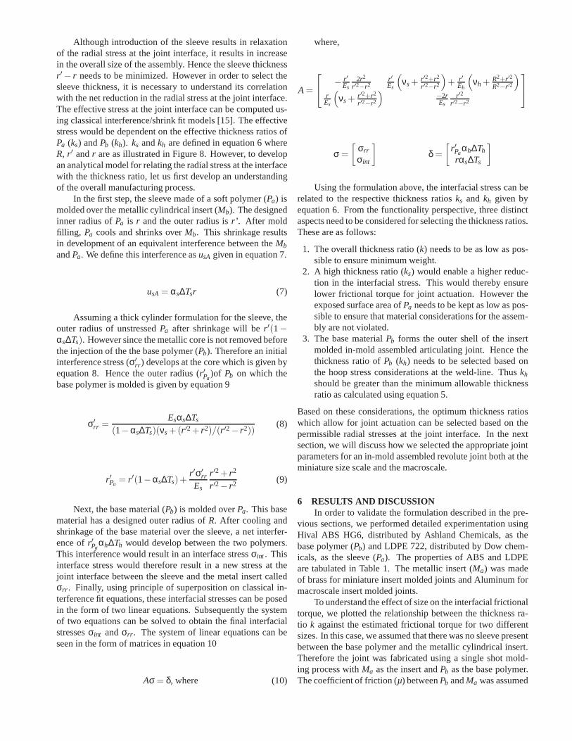
Although introduction of the sleeve results in relaxationof the radial stress at the joint interface, it results in increasein the overall size of the assembly. Hence the sleeve thicknessr ′− r needs to be minimized. However in order to select thesleeve thickness, it is necessary to understand its correlationwith the net reduction in the radial stress at the joint interface.The effective stress at the joint interface can be computed us-ing classical interference/shrink fit models [15]. The effectivestress would be dependent on the effective thickness ratiosofPa (ks) andPb (kh). ks andkh are defined in equation 6 whereR, r ′ andr are as illustrated in Figure 8. However, to developan analytical model for relating the radial stress at the interfacewith the thickness ratio, let us first develop an understandingof the overall manufacturing process.
In the first step, the sleeve made of a soft polymer (Pa) ismolded over the metallic cylindrical insert (Mb). The designedinner radius ofPa is r and the outer radius isr’ . After moldfilling, Pa cools and shrinks overMb. This shrinkage resultsin development of an equivalent interference between theMb
andPa. We define this interference asusA given in equation 7.
usA= αs∆Tsr (7)
Assuming a thick cylinder formulation for the sleeve, theouter radius of unstressedPa after shrinkage will ber ′(1−
αs∆Ts). However since the metallic core is not removed beforethe injection of the the base polymer (Pb). Therefore an initialinterference stress (σ′
rr ) develops at the core which is given byequation 8. Hence the outer radius (r ′Pa
)of Pb on which thebase polymer is molded is given by equation 9
σ′
rr =Esαs∆Ts
(1−αs∆Ts)(νs+(r ′2+ r2)/(r ′2− r2))(8)
r ′Pa= r ′(1−αs∆Ts)+
r ′σ′
rr
Es
r ′2+ r2
r ′2− r2 (9)
Next, the base material (Pb) is molded overPa. This basematerial has a designed outer radius ofR. After cooling andshrinkage of the base material over the sleeve, a net interfer-ence ofr ′Pa
αh∆Th would develop between the two polymers.This interference would result in an interface stressσint . Thisinterface stress would therefore result in a new stress at thejoint interface between the sleeve and the metal insert calledσrr . Finally, using principle of superposition on classical in-terference fit equations, these interfacial stresses can beposedin the form of two linear equations. Subsequently the systemof two equations can be solved to obtain the final interfacialstressesσint andσrr . The system of linear equations can beseen in the form of matrices in equation 10
Aσ = δ, where (10)
where,
A=
−r ′Es
2r2
r ′2−r2r ′Es
(
νs+r ′2+r2
r ′2−r2
)
+ r ′Eh
(
νh+R2+r ′2
R2−r ′2
)
rEs
(
νs+r ′2+r2
r ′2−r2
)
−2rEs
r ′2
r ′2−r2
σ =
[
σrr
σint
]
δ =
[
r ′Paαh∆Th
rαs∆Ts
]
Using the formulation above, the interfacial stress can berelated to the respective thickness ratiosks and kh given byequation 6. From the functionality perspective, three distinctaspects need to be considered for selecting the thickness ratios.These are as follows:
1. The overall thickness ratio (k) needs to be as low as pos-sible to ensure minimum weight.
2. A high thickness ratio (ks) would enable a higher reduc-tion in the interfacial stress. This would thereby ensurelower frictional torque for joint actuation. However theexposed surface area ofPa needs to be kept as low as pos-sible to ensure that material considerations for the assem-bly are not violated.
3. The base materialPb forms the outer shell of the insertmolded in-mold assembled articulating joint. Hence thethickness ratio ofPb (kh) needs to be selected based onthe hoop stress considerations at the weld-line. Thuskh
should be greater than the minimum allowable thicknessratio as calculated using equation 5.
Based on these considerations, the optimum thickness ratioswhich allow for joint actuation can be selected based on thepermissible radial stresses at the joint interface. In the nextsection, we will discuss how we selected the appropriate jointparameters for an in-mold assembled revolute joint both at theminiature size scale and the macroscale.
6 RESULTS AND DISCUSSIONIn order to validate the formulation described in the pre-
vious sections, we performed detailed experimentation usingHival ABS HG6, distributed by Ashland Chemicals, as thebase polymer (Pb) and LDPE 722, distributed by Dow chem-icals, as the sleeve (Pa). The properties of ABS and LDPEare tabulated in Table 1. The metallic insert (Ma) was madeof brass for miniature insert molded joints and Aluminum formacroscale insert molded joints.
To understand the effect of size on the interfacial frictionaltorque, we plotted the relationship between the thickness ra-tio k against the estimated frictional torque for two differentsizes. In this case, we assumed that there was no sleeve presentbetween the base polymer and the metallic cylindrical insert.Therefore the joint was fabricated using a single shot mold-ing process withMa as the insert andPb as the base polymer.The coefficient of friction (µ) betweenPb andMa was assumed

Table 1: PROPERTIES OF BASE POLYMER (Pb) ANDSLEEVE (Pa)
ABS(Pb) LDPE(Pa)
Young’s Modulus (GPa) 2.7 0.139
Coefficient of Thermal Ex-pansion
90E-6 190E-6
Poisson’s Ratio 0.4 0.3
Yield Strength (MPa) 40 12
Solidification Temperature(Celcius)
97 60
to be 0.4. The room temperature to which the polymers coolwas assumed to be 28oC. We then calculated the interfacialfrictional torque using equations 1 and 2. These results areshown in Figure 9. From the plot it is evident that the sizeplays a prominent role in the frictional torque.
0 0.5 1 1.5 20
0.05
0.1
0.15
0.2
k
Inte
rfac
ial t
orqu
e pe
r un
it le
ngth
(N
−m
/mm
)
r = 0.4 mm
r = 3.175 mm
Fig. 9: INTERFACIAL FRICTIONAL TORQUE V/STHICKNESS RATIO FOR TWO JOINT SIZES
To develop a mold design to fabricate a revolute joint asillustrated in Figure 4, we had to first select the dimensionalparameters for the joint. These dimensional parameters arede-scribed in Figure 5. For selecting the thicknesst of the joint,we followed the strategy outlined in section 3 to calculate theminimum thickness ratiok. The average weld line strengthfor ABS was obtained from Ananthanarayanan et al. [19] tobe 75% of the base material. Applying an overall factor ofsafety of 2, the effective factor of safetyFSWL was calculatedas 2.667. The yield strengthσy for ABS is defined as 40 MPa(Table 1). Hence the maximum allowable hoop stress as de-fined in equation 5 was 15 MPa. Hence to calculate the thick-ness ratiok, we plotted it against the hoop stress as describedin equation 5. This is shown in Figure 10. The plot shows thatthe hoop stress in the part decreases with the increasing thick-ness ratio. From this plot, we obtained the minimum allowablevalue for the thickness ratiok to be 0.35. We then selectedthe other dimensional parameters shown in Figure 5 using thestrategy described in section 2.1. These dimensions, for two
different sizes, are shown in Table 2. The thicknesst had tobe selected so that the thickness ratiok was greater than theminimum allowable value of 0.35. For the macroscale joint (r= 3.175 mm), we designed the thickness to be 1.11 mm. Thisled to an effective thickness ratiok = 0.35. However for thejoint size ofr = 0.4 mm, due to the manufacturing constraintsposed by the minimum moldable thickness, the thickness hadto be selected as 0.4 mm. This led to an effective thicknessratiok = 1.
0 0.5 1 1.5 2
1.3
1.4
1.5
1.6
x 107
σ θ (P
a)
k
Hoop Stress
Maximum Allowable Stress
Fig. 10: HOOP STRESS V/S THICKNESS RATIO
Table 2: DIMENSIONAL PARAMETERS FOR IN MOLDASSEMBLED REVOLUTE JOINT FABRICATED USINGINSERT MOLDING STRATEGY
r=0.4 mm r = 3.175 mm
s 1 mm 1.27 mm
c 1.5 mm 8.9 mm
ct 1 mm 1.5 mm
t 0.4 mm 1.11 mm
Using the parameters shown in Table 2, we manufac-tured in-mold assembled revolute joints at both macroscaleand miniature scale on a Milacron Babyplast injection mold-ing machine. A functional in-mold assembled revolute jointsat the miniature size (joint radius = 0.4 mm) is illustrated inFigure 11. The force required to overcome the interfacial fric-tional torque of this joint was low enough to allow for smoothactuation of the miniature revolute joint. Hence we concludedthat for the miniature scale, a single shot molding strategywould suffice. i.e. We did not need to introduce a sleeve atthe interface to relax the radial stress at the joint interface.
However at the macroscale, the strategy resulted in real-ization of jammed revolute joints. This resulted in high forcesrequired to overcome interfacial frictional torque required forjoint actuation. Hence to successfully fabricate functional rev-olute joints at this size scale, it was necessary for us to intro-duce a sleeve to reduce the radial stress at the joint interface.In order to select the appropriate dimensions for the in-moldassembled revolute joint, we had to understand the effect of

Fig. 11: IN-MOLD ASSEMBLED MINIATURE REVO-LUTE JOINT FABRICATED USING INSERT MOLDING
the sleeve on the stress relaxation. To model this effect weadopted the approach described in the previous section. Tovalidate the theoretical approach that was described in thepre-vious section, we also performed finite element analysis us-ing ANSYS 11.0 to predict the radial stress at the joint inter-face. This analysis was setup as a simple shrinkage simulationof a composite ring as illustrated in Figure 8. Subsequently,we conducted the simulation independently for seven differ-ent combinations ofks andkh. The results of this evaluationare plotted in Figure 12. The plot shows the stress relaxationcaused by the sleeve, made of LDPE, for a revolute joint ofthree different overall thickness ratios (k). The results of thefinite element analysis are overlayed on the analytical model.The results show excellent agreement between the analyticalmodel and the finite element simulations.
The thickness ratio (ks) can be increased only until theresulting thickness ratio (kh) of the base polymer (ABS) doesnot fall below the permissible limit. This permissible limit isdefined based on the allowable hoop stress at the weld line asdefined by equation 5. This point, for the three different valuesof overall thickness ratio (k), is illustrated in the plot shown inFigure 12.
0 0.1 0.2 0.3 0.4 0.5 0.6 0.7 0.8 0.9 10
0.5
1
1.5
2
2.5x 10
6
σ rr(P
a)
ks
Analytical (k=1)
Analytical (k=0.8)
Analytical (k=0.4)
Finite Element (k=1)
Finite Element (k=0.8)
Finite Element (k=0.4)
Fig. 12: RADIAL STRESS RELAXATION DUE TO PRES-ENCE OF SLEEVE MADE OF SOFT POLYMER
Figure 13 shows a successfully actuating in-mold assem-bled macroscale revolute joint using the insert molding strat-egy descrbied in this paper. For successful manufacturing ofthe macroscale revolute joint (diameter = 3.175 mm), the per-missible interfacial frictional torque was approximately0.075N-m/mm. This resulted in an allowable radial stress of 3 MPa
Fig. 13: FUNCTIONING IN-MOLD ASSEMBLEDMACROSCALE REVOLUTE JOINT FABRICATEDUSING INSERT MOLDING
Table 3: DESIGNED THICKNESS RATIO AND RESULT-ING DIMENSIONS FOR MACROSCALE IN-MOLD AS-SEMBLED REVOLUTE JOINT
k 0.8 r 3.175 mm
ks 0.2 r’ 3.81 mm
kh 0.5 R 5.715 mm
at the joint interface. After adopting manufacturability con-straints for injection molding such as mold machining, moldfilling and ejection, the designed thickness ratios and the re-sulting dimensions of the revolute joint are shown in Table 3.
7 CASE STUDY: MINIMALLY INVASIVE SURGICALROBOTSurgical robots have been defined as a powered computer
controlled manipulator with artificial sensing that can be re-programmed to move and position tools to carry out a range ofsurgical tasks [20]. Due to the high dexterity and maneuver-ability desired for surgical robots, the need for higher degreesof freedom is becoming increasingly important. However dueto the requirement of several delicate medical procedures tohave minimally invasive robots to perform surgery, there isalso a significant need to miniaturize surgical robots [21,22].
One of the most significant challenges associated withdevelopment of miniature multiple degree of freedom robotslies in its fabrication. Traditional fabrication methods suchas machining and assembly are not suitable at the small scaleparadigm at which minimally invasive surgical robots lie. Toaddress this problem, researchers at Carnegie Mellon Univer-sity and Stanford have developed the shape deposition man-ufacturing (SDM) process [23] for making fully embeddedsmart robotic structures. These processes make intelligent useof both standard joints and flexures to realize multiple degreeof freedom structures. Hence they are very powerful prototyp-ing methods for fabricating highly articulating robotic struc-tures. However SDM requires several fabrication and post fab-rication steps to complete the manufacturing. This increasesthe overall cycle time for fabricating each robot and therebythe cost of the robot. To offset sterilization costs of medi-cal robots used in minimally invasive surgery, it is desirableto have disposable medical robots [24]. However to accom-plish this, it is essential that the manufacturing process usedfor fabrication of the robots be cost effective. Bejgerowski et

al. [25] have previously developed a method for using injectionmolded flexures for high strength to weight ratio structures.As part of their work, they presented a powerful paradigm forlow cost manufacturing of mechanisms. However the avail-able choice of materials for injection molded flexures is lim-ited. Rigid body joints on the other hand have a much widerpool of material options. Hence when a constraint on the ma-terial is posed by its biocompatibility (in surgical devices), itis essential to develop a more material independent fabricationmethod.
The in-mold assembly method using insert molding, il-lustrated in this paper, provides a powerful alternative tofab-ricating highly articulating miniature structues. Using an in-novative mold design, the insert molding method described inthis paper, can be used to fabricate multiple degree of free-dom robotic structures in a single molding shot. To illustratethis, we manufactured a prototype of a 9 degree of freedomarticulating structure for a robot with potential application inneurosurgery. The design of this articulating structure consistsof 10 independent parts which are connected by metallic moldinserts of 1.58 mm diameter. The articulating structure wasmanufactured in a single injection shot using the insert mold-ing method described in this paper. Owing to the small jointsizes, the radial stress at the joint interface were sufficientlylow. Hence no sleeve was required for successful articulationof the joints. Figure 14 shows the manufacturing steps for fab-ricating the 9 DOF articulating structure in a single injectionshot.
The robot fabricated using the insert molding approachcan be actuated using shape memory alloy based actuation.Bejgerowski et al. [26] have discussed a method to optimallyembed actuators in injection molded parts. Additionally, Pap-pafotis et al. [27] demonstrated the use of shape memory alloysfor actuating an MRI compatible miniature robot. Their robotprototype is fabricated using machining and assembly. As partof this work, we have also demonstrated the use of shape mem-ory alloys for actuating the 9 degree of freedom robot that wehave manufactured using insert molding methods. Figure 14also illustrates the 9 degree of freedom robot wired with shapememory alloys. The shape memory alloy based actuation strat-egy provides a low weight solution for independent control ofeach degree of freedom of the robot.
One of the most noteworthy benefits to using an injec-tion molding based approach to manufacturing robots is itsadvantage in mass production. To illustrate this, we comparedthe cost of fabricating the 9 degree of freedom robot structureusing the following three strategies 1) Machining and assem-bly [27], 2) In-mold assembly [10], and 3) In-mold assemblyusing insert molding (this work). For the purpose of this com-parison, we consider the production time as a direct indica-tion of the production cost. Considering that labor cost is oneof the most prominent factors contributing to the overall pro-duction cost, the authors feel, this is a reasonable assumption.Table 4 shows an estimate of the time required to complete dif-ferent aspects of the production using the different approaches.Figure 15 illustrates the comparison of the cost of fabricatingupto 30 prototypes of a 9 degree of freedom robot structureusing the different manufacturing approaches outlined above.
Shape Memory Alloy Actuation
Fig. 14: 9 DEGREE OF FREEDOM ROBOT STRUCTUREMANUFACTURED USING INSERT MOLDING
The graph clearly demonstrates the advantage of using an in-mold assembly approach to fabricating robots over machiningand assembly. This advantage is increasingly prominent withincreasing number of robots that need to be fabricated. Thegraph also illustrates that using the in-mold assembly approachwith insert molding is significantly more advantageous thanusing the conventional in-mold assembly approach to manu-facturing. This is because use of the insert molding approacheliminates the post fabrication assembly step completely.Thisis because, use of this approach allows manufacturers to fabri-cate the complete 9 DOF robot in a single injection shot.
8 CONCLUSIONSThis paper presents the first successful demonstration of
the insert molding method for manufacturing in-mold assem-

Table 4: PRODUCTION TIME ESTIMATE IN MINUTESFOR 9 DOF ROBOT USING DIFFERENT MANUFACTUR-ING STRATEGIES
Machiningand As-sembly
In-moldAssembly
In-moldAssemblyusing insertmolding
Mold manu-facturing timeper link
N.A. 40 180
Part man-ufacturingtime for 9 linkrobot
240 10 1.5
Mold insertfabricationtime
N.A. N.A. 30
Assemblytime
60 30 N.A.
Fig. 15: COST COMPARISON BASED ON PRODUC-TION TIME ESTIMATE FOR FABRICATING A 9 DOFROBOT STRUCTURE USING DIFFERENT MANUFAC-TURING STRATEGIES
bled mechanical assemblies. We have presented two distinctstrategies which can be used at the miniature size scale and themacroscale respectively to fabricate mechanical assemblies.Cylindrical mold inserts made of Aluminum/Brass are usedas the articulating members of the in-mold assembled joints.Results reported in this paper show that the shrinkage of thepolymer around the cylindrical mold inserts leads to the de-velopment of radial stresses at the joint interface. These radialstresses are responsible for the joint friction which leadstojamming. We have presented a theoretical framework to pre-dict the radial stresses that appear at the joint interface dueto the in-mold assembly process. At the miniature size scale,the frictional torque resulting from the radial stresses are suf-ficiently low. Therefore it does not interfere with the function-ality of the joint.
The modeling results presented in this paper reveal thatthe strength of the weld-line formed at the joint interface sig-
nificantly impact the overall strength of the robotic assembly.However this can be overcome by choosing the right dimen-sional parameters while accounting for the structural short-coming resulting from the appearance of the weld-line. Wehave presented an analytical model to compute the minimumallowable joint thickness in in-mold assembled revolute joints.Increase in the size of the joint results in appearance of higherfrictional torque at the joint interface. We have developedamethod to control the radial stresses at the joint interfacebyusing a soft polymer at the joint interface. We have also pre-sented a rigorous theoretical framework to predict the radialstresses at the joint interface due to the presence of the softpolymer at the interface. These results can be used to selecttheoptimum dimensional parameters for fabricating functional in-mold assembled robotic structures at any size scale.
We have used the methods presented in this paper to suc-cessfully prototype a 9 degree of freedom articulating structurefor a medical robot with applications in neurosurgery. Thisar-ticulating structure is envisioned to be actuated and controlledusing shape memory alloys.
AchnowledgementsThis research has been supported by NIH grant #
1R21EB008796. Opinions expressed in this paper are thoseof the authors and do not necessarily reflect opinions of thesponsors.
References[1] Ananthanarayanan, A., Gupta, S. K., and Bruck, H. A.,
2010. “Characterization of a reverse molding sequence atthe mesoscale for in-mold assembly of revolute joints”.Polymer Engineering & Science,50(9), pp. 1843–1852.
[2] Moon, S. I., Monson, L. L., and Extrand, C. W., 2006.“Insert-molded poly(ether imide)/carbon fiber poly(etherether ketone) bimaterial composites: Fracture and inter-facial analysis”. Journal of Applied Polymer Science,102(3), pp. 2362–2371.
[3] Teh, N. J., Conway, P. P., Palmer, P. J., Prosser, S., andKioul, A., 2000. “Statistical optimisation of thermoplas-tic injection moulding process for the encapsulation ofelectronic subassembly”.Journal of Electronics Manu-facturing,10, p. 171.
[4] Webb, D. P., Hutt, D. A., Hopkinson, N., Conway,P. P., and Palmer, P. J., 2009. “Packaging of microflu-idic devices for fluid interconnection using thermoplas-tics”. Journal of Microelectromechanical Systems,18(2),pp. 354–362.
[5] Grujicic, M., Sellappan, V., Pandurangan, B., Li, G.,Vahidi, A., Seyr, N., Erdmann, M., and Holzleitner,J., 2008. “Computational analysis of injection-moldingresidual-stress development in direct-adhesion polymer-to-metal hybrid body-in-white components”.JournalOf Materials Processing Technology,203(1-3), Jul 18,pp. 19–36.
[6] Ramani, K., and Zhao, W., 1997. “The evolution ofresidual stresses in thermoplastic bonding to metals”.In-

ternational Journal Of Adhesion And Adhesives,17(4),pp. 353–357.
[7] Priyadarshi, A., Gupta, S., Gouker, R., Krebs, F.,Shroeder, M., and Warth, S., 2007. “Manufacturingmulti-material articulated plastic products using in-moldassembly”.International Journal of Advanced Manufac-turing Technology,32(3-4), pp. 350–365.
[8] Ananthanarayanan, A., Gupta, S., and Bruck, H., 2008.“Characterization and control of plastic deformation inpremolded components in in-mold assembled mesoscalerevolute joints using bi-directional filling strategy”. InAll India Manufacturing Technology and DevelopmentResearch.
[9] Ananthanarayanan, A., Gupta, S., and Bruck, H., 2009.“Characterization and control of pin diameter during in-mold assembly of mesoscale revolute joints”. In NorthAmerican Manufacturing Research Institute, Vol. 37.
[10] Ananthanarayanan, A., Gupta, S., and Bruck, H., 2009.“Characterization and control of plastic deformation inmesoscale premolded components to realize in-mold as-sembled mesoscale revolute joints”.Polymer Engineer-ing & Science,49(2), pp. 293–304.
[11] Ananthanarayanan, A., Thamire, C., and Gupta, S.,2007. “Investigation of revolute joint clearances createdby an in-mold assembly process”. In IEEE: InternationalSymposium on Assembly and Manufacturing.
[12] Chen, Z. B., Giacomin, A. J., and Turng, L. S., 2006.“Flash”. Polymer Engineering and Science,46(3),pp. 241–247.
[13] Kwon, K., Isayev, A. I., and Kim, K. H., 2006. “Theo-retical and experimental studies of anisotropic shrinkagein injection moldings of various polyesters”.Journal ofApplied Polymer Science,102(4), pp. 3526–3544.
[14] Kwon, K., Isayev, A. I., Kim, K. H., and van Swe-den, C., 2006. “Theoretical and experimental studies ofanisotropic shrinkage in injection moldings of semicrys-talline polymers”. Polymer Engineering and Science,46(6), pp. 712–728.
[15] Hamrock, B. J., Schmid, S. R., and Jacobson, B. O.,2007. Fundamentals of Machine Elements, 2nd ed.McGraw-Hill Science/Engineering/Math.
[16] Wu, C., and Liang, W., 2005. “Effects of geometry andinjection-molding parameters on weld-line strength”.Polymer Engineering and Science,45(7), pp. 1021–1030.
[17] Selden, R., 1997. “Effect of processing on weld-linestrength in five thermoplastics”.Polymer Engineeringand Science,37(1), pp. 205–218.
[18] Gouker, R., Gupta, S., Bruck, H., and Holzschuh,T., 2006. “Manufacturing of multi-material compliantmechanisms using multi-material molding”.Interna-tional Journal of Advanced Manufacturing Technology,30(11-12), pp. 1049–1075.
[19] Ananthanarayanan, A., Gupta, S., and Bruck, H., 2008.“Mechanical characterization of cold weld-lines andmeld lines in mesoscopic revolute joints for bioinspiredstructures”. In SEM Annual Conference and Exposition.
[20] Davies, B., 2000. “A review of robotics in surgery”.Pro-
ceedings of the Institution of Mechanical Engineers PartH-Journal of Engineering in Medicine,214(H1), p. 129.
[21] Camarillo, D. B., Krummel, T. M., and Salisbury, J. K.,2004. “Robotic technology in surgery: past, present, andfuture”. American Journal of Surgery,188(4A), pp. 2S–15S.
[22] Louw, D. F., Fielding, T., McBeth, P. B., Gregoris, D.,Newhook, P., and Sutherland, G. R., 2004. “Surgicalrobotics: A review and neurosurgical prototype develop-ment”. Neurosurgery,54(3), pp. 525–536.
[23] Cutkosky, M. R., and Kim, S., 2009. “Design andfabrication of multi-material structures for bioinspiredrobots”. Philosophical Transactions Of The Royal Soci-ety A-mathematical Physical And Engineering Sciences,367(1894), MAY 13, pp. 1799–1813.
[24] Walsh, C. J., Hanumara, N. C., Slocum, A. H., Shepard,J.-A., and Gupta, R., 2008. “A patient-mounted, teler-obotic tool for ct-guided percutaneous interventions”.Journal of Medical Devices,2(1), p. 011007.
[25] Bejgerowski, W., Ananthanarayanan, A., Mueller, D.,and Gupta, S. K., 2009. “Integrated product and processdesign for a flapping wing drive mechanism”.Journal ofMechanical Design,131(6), p. 061006.
[26] Bejgerowski, W., Gupta, S. K., and Bruck, H. A., 2009.“A systematic approach for designing multifunctionalthermally conducting polymer structures with embed-ded actuators”.Journal of Mechanical Design,131(11),p. 111009.
[27] Pappafotis, N., Bejgerowski, W., Gullapalli, R., Simard,J., Gupta, S., and Desai, J., 2008. “Towards designand fabrication of a miniature mri-compatible robot forapplications in neurosurgery”. In ASME 2008 Inter-national Design Engineering Technical Conferences &Computers and Information in Engineering ConferenceIDETC/CIE.


![This document contains the draft version of the following ...terpconnect.umd.edu/~skgupta/Publication/VR07_Brough_draft.pdfassembly system [9]. Gupta et al. describe a system for prototyping](https://img.dokumen.tips/doc/110x75/5ea82880e26406643b50d073/this-document-contains-the-draft-version-of-the-following-skguptapublicationvr07broughdraftpdf.jpg)