Embed Size (px)
Citation preview

ThinkPad R32 Series HardwareMaintenance Manual
���

Before using this information and the product it supports,be sure to read the general information under“Introduction” on page 1, and “Notices” on page 241.
First Edition(November 2002)
The following paragraph does not apply to the UnitedKingdom or any country where such provisions areinconsistent with local law:
INTERNATIONAL BUSINESS MACHINES CORPORATIONPROVIDES THIS PUBLICATION ″AS IS″ WITHOUT ANYWARRANTY OF ANY KIND, EITHER EXPRESS ORIMPLIED, INCLUDING, BUT NOT LIMITED TO, THELIMITED WARRANTIES OF MERCHANTABILITY ORFITNESS FOR A PARTICULAR PURPOSE. Some statesdo not allow disclaimers or express or implied warranties incertain transactions; therefore, this statement may notapply to you.
This publication could include technical inaccuracies ortypographical errors. Changes are periodically made to theinformation herein; these changes will be incorporated innew editions of the publication. IBM may makeimprovements or changes in the products or the programsdescribed in this publication at any time.
Requests for technical information about IBM productsshould be made to your IBM Authorized Dealer or yourIBM Marketing Representative.
© Copyright International Business MachinesCorporation 2002. All rights reserved. Note to USGovernment Users — Documentation related to restrictedrights — Use, duplication, or disclosure is subject torestrictions set forth in GSA ADP Schedule Contract withIBM Corp.

Preface
About this manual
This manual contains service and reference information forIBM ThinkPad R32 Series Hardware Maintenance Manualproducts. Use this manual along with the advanceddiagnostic tests to troubleshoot problems effectively.
The manual is divided into sections as follows:
v The Introduction section provides general information,guidelines, and safety information required to servicecomputers.
v The product-specific section includes service, reference,and product-specific parts information.
ImportantThis manual is intended for trained servicers whoare familiar with ThinkPad products. Use thismanual along with the advanced diagnostic tests totroubleshoot problems effectively. Before servicingan IBM ThinkPad product, be sure to review thesafety information under “Safety Notices(Multi-lingual Translations)” on page 3,“SafetyInformation” on page 11 and “Laser ComplianceStatement” on page 16
iii

iv ThinkPad R32 Series
Contents
Preface . . . . . . . . . . . . . . . iii
ThinkPad R32 Series Hardware Maintenance Manual 1Introduction . . . . . . . . . . . . . . 1
Important Service Information. . . . . . . . 1Drive and Diskette Compatibility Matrix . . . . . 2Safety Notices (Multi-lingual Translations) . . . . 3Safety Information. . . . . . . . . . . 11Laser Compliance Statement . . . . . . . 16
General Descriptions . . . . . . . . . . . 19Read this first . . . . . . . . . . . . . 20
What to do first . . . . . . . . . . . 20FRU replacement notices . . . . . . . . . 22
LCD replacement notice . . . . . . . . . 22Screw notices . . . . . . . . . . . . 22System board/LCD/Inverter replacement notice 23
Related service information . . . . . . . . . 26Power button as reset switch . . . . . . . 26Running a low-level format . . . . . . . . 26Service Web site . . . . . . . . . . . 26Passwords . . . . . . . . . . . . . 26Power management features . . . . . . . 28Fn key combinations . . . . . . . . . . 30Product recovery program . . . . . . . . 30Flash BIOS. . . . . . . . . . . . . 33
Checkout guide . . . . . . . . . . . . 34Testing the computer . . . . . . . . . . 34Related service information . . . . . . . . 35Power systems checkout. . . . . . . . . 36
Symptom-to-FRU Index . . . . . . . . . . 39Numeric Error Codes and Messages . . . . . 39Beep Symptoms . . . . . . . . . . . 47LCD-Related Symptoms . . . . . . . . . 49Keyboard/TrackPoint-Related Symptoms . . . . 50Indicator-Related Symptoms. . . . . . . . 50Power-Related Symptoms . . . . . . . . 50Memory-Related Symptom . . . . . . . . 51Audio-Related Symptoms . . . . . . . . 51PC Card (PCMCIA)-Related Symptoms . . . . 51Power Management-Related Symptoms . . . . 52Peripheral-Device-Related Symptoms . . . . . 52Modem-Related Symptom . . . . . . . . 53Operating System-Related Symptom . . . . . 53Intermittent Problems. . . . . . . . . . 53Undetermined Problems . . . . . . . . . 54
ThinkPad R32 Series Part I . . . . . . . . . 55Product overview . . . . . . . . . . . 56FRU removals and replacements . . . . . . 62Locations . . . . . . . . . . . . . 98Parts list . . . . . . . . . . . . . 101
v

ThinkPad R32 Series Part II . . . . . . . . 115Product overview . . . . . . . . . . 116FRU removals and replacements . . . . . . 122Locations . . . . . . . . . . . . . 158Parts list . . . . . . . . . . . . . 161
ThinkPad R32 Series Part III . . . . . . . . 175Product overview . . . . . . . . . . 176FRU removals and replacements . . . . . . 182Locations . . . . . . . . . . . . . 219Parts list . . . . . . . . . . . . . 222
Notices . . . . . . . . . . . . . . 241Trademarks . . . . . . . . . . . . . 242
vi ThinkPad R32 Series

ThinkPad R32 Series HardwareMaintenance Manual
Introduction
Important Service Information
ImportantDiskette fixes are customer-installable. The diskettefixes are posted on the IBM support sitehttp://www.pc.ibm.com/support/ .
Advise customers to contact the PC CompanyHelpCenter at 800-772-2227 if they need assistancein obtaining or installing any diskette fixes.
Customers in Canada should call IBM HelpPC at800-565-3344 for assistance or downloadinformation.
FRU Replacement Strategy
Before Replacing PartsEnsure that all diskette fixes are installed prior toreplacing any FRUs listed in this manual.
Use the following strategy to prevent unnecessary FRUreplacement and service expense:
v If you are instructed to replace a FRU and that doesnot correct the problem, reinstall the original FRUbefore you continue.
v Some computers have both a processor board and asystem board. If you are instructed to replace either theprocessor board or the system board, and the first boardthat you replaced does not correct the problem, reinstallthe original board, then replace the other (processor orsystem) board.
v If an adapter or device consists of more than one FRU,an error code may be caused by any of the FRUs.Before replacing the adapter or device, remove theFRUs, one by one, to see if the symptoms change.Replace only the FRU that changed the symptoms.
Attention: A customized setup configuration (other thandefault settings) may exist on the computer you areservicing. Running Automatic Configuration may alter thosesettings. Note the current configuration settings (using theView Configuration option) and verify that the settings arein place when service is complete.
1

Hard Disk Drive Replacement StrategyAlways try to run a low-level format before replacing a harddisk drive.
Attention: The drive startup sequence in the computeryou are servicing might have been changed. Be extremelycareful during write operations such as copying, saving, orformatting. Data or programs can be over-written if youselect an incorrect drive.
How to Use Error MessagesUse the error codes displayed on the screen to diagnosefailures. If more than one error code is displayed, begin thediagnosis with the first error code. The cause of the firsterror code can result in false error codes being displayed.If no error code is displayed, see if the error symptom islisted in the Symptom-to-FRU Index for the computer youare servicing.
How to Read POST Error MessagesPOST error messages are displayed on the screen asthree, four, five, or eight digits. The error messages thatcan be displayed as shorter POST messages arehighlighted in this index. Some digits will representdifferent information for SCSI errors versus non-SCSIerrors.
All SCSI devices are set to a different SCSI ID. DuplicateSCSI ID settings can generate a false error message. Usethe SCSI ID to determine whether the error message iscoming from an internal or an external device.
Drive and Diskette Compatibility MatrixThe following table provides identification information for3.5-inch drives.
Diskette Drive Identifying Mark
3.5-Inch - 1.44MB 1.44 on the eject button
3.5-Inch - 2.88MB 2.88 on the eject button
The following table provides compatibility information for3.5-inch diskettes and 3.5-inch diskette drives.
Diskette Capacity 1.44MB Drive 2.88MB Drive
1.0MB Read/Write Read/Write
2.0MB Read/Write Read/Write
4.0MB Not Compatible Read/Write
2 ThinkPad R32 Series

Safety Notices (Multi-lingualTranslations)In this manual, safety notices appear in English with apage number reference to the appropriate multi-lingual,translated safety notice found in this section.
The following safety notices are provided in English,French, German, Italian, and Spanish.
Safety Notice 1Before the computer is powered-on after FRUreplacement, make sure all screws, springs, or othersmall parts are in place and are not left loose insidethe computer. Verify this by shaking the computerand listening for rattling sounds. Metallic parts ormetal flakes can cause electrical shorts.
Avant de remettre l’ordinateur sous tension aprèsremplacement d’une unité en clientèle, vérifiez quetous les ressorts, vis et autres pièces sont bien enplace et bien fixées. Pour ce faire, secouez l’unité etassurez-vous qu’aucun bruit suspect ne se produit.Des pièces métalliques ou des copeaux de métalpourraient causer un court-circuit.
Bevor nach einem FRU-Austausch der Computerwieder angeschlossen wird, muβ sichergestelltwerden, daβ keine Schrauben, Federn oder andereKleinteile fehlen oder im Gehäuse vergessenwurden. Der Computer muβ geschüttelt und aufKlappergeräusche geprüft werden. Metallteile oder-splitter können Kurzschlüsse erzeugen.
Prima di accendere l’elaboratore dopo che é stataeffettuata la sostituzione di una FRU, accertarsi chetutte le viti, le molle e tutte le altri parti di piccoledimensioni siano nella corretta posizione e nonsiano sparse all’interno dell’elaboratore. Verificareciò scuotendo l’elaboratore e prestando attenzionead eventuali rumori; eventuali parti o pezzettimetallici possono provocare cortocircuiti pericolosi.
Antes de encender el sistema despues de sustituiruna FRU, compruebe que todos los tornillos,muelles y demás piezas pequeñas se encuentranen su sitio y no se encuentran sueltas dentro delsistema. Compruébelo agitando el sistema yescuchando los posibles ruidos que provocarían.Las piezas metálicas pueden causar cortocircuitoseléctricos.
MT 2658/2659/2677 3

Safety Notice 2Some standby batteries contain a small amount ofnickel and cadmium. Do not disassemble it,recharge it, throw it into fire or water, or short-circuitit. Dispose of the battery as required by localordinances or regulations. Use only the battery inthe appropriate parts listing. Use of an incorrectbattery can result in ignition or explosion of thebattery.
Certaines batteries de secours contiennent du nickelet du cadmium. Ne les démontez pas, ne lesrechargez pas, ne les exposez ni au feu ni à l’eau.Ne les mettez pas en court-circuit. Pour les mettreau rebut, conformez-vous à la réglementation envigueur. Lorsque vous remplacez la pile desauvegarde ou celle de l’horloge temps réel, veillezà n’utiliser que les modèles cités dans la liste depièces détachées adéquate. Une batterie ou unepile inappropriée risque de prendre feu oud’exploser.
Die Bereitschaftsbatterie, die sich unter demDiskettenlaufwerk befindet, kann geringe MengenNickel und Cadmium enthalten. Sie darf nur durchdie Verkaufsstelle oder den IBM Kundendienstausgetauscht werden. Sie darf nicht zerlegt,wiederaufgeladen, kurzgeschlossen, oder Feueroder Wasser ausgesetzt werden. Die Batterie kannschwere Verbrennungen oder Verätzungenverursachen. Bei der Entsorgung die örtlichenBestimmungen für Sondermüll beachten. BeimErsetzen der Bereitschafts- oder Systembatterie nurBatterien des Typs verwenden, der in derErsatzteilliste aufgeführt ist. Der Einsatz falscherBatterien kann zu Entzündung oder Explosionführen.
4 ThinkPad R32 Series

(Continued)Alcune batterie di riserva contengono una piccolaquantità di nichel e cadmio. Non smontarle,ricaricarle, gettarle nel fuoco o nell’acqua nécortocircuitarle. Smaltirle secondo la normativa invigore (DPR 915/82, successive disposizioni edisposizioni locali). Quando si sostituisce la batteriadell’RTC (real time clock) o la batteria di supporto,utilizzare soltanto i tipi inseriti nell’appropriatoCatalogo parti. L’impiego di una batteria non adattapotrebbe determinare l’incendio o l’esplosione dellabatteria stessa.
Algunas baterías de reserva contienen una pequeñacantidad de níquel y cadmio. No las desmonte, nirecargue, ni las eche al fuego o al agua ni lascortocircuite. Deséchelas tal como dispone lanormativa local. Utilice sólo baterías que seencuentren en la lista de piezas. La utilización deuna batería no apropiada puede provocar la ignicióno explosión de la misma.
MT 2658/2659/2677 5

Safety Notice 3The battery pack contains small amounts of nickel.Do not disassemble it, throw it into fire or water, orshort-circuit it. Dispose of the battery pack asrequired by local ordinances or regulations. Useonly the battery in the appropriate parts listing whenreplacing the battery pack. Use of an incorrectbattery can result in ignition or explosion of thebattery.
La batterie contient du nickel. Ne la démontez pas,ne l’exposez ni au feu ni à l’eau. Ne la mettez pasen court-circuit. Pour la mettre au rebut,conformez-vous à la réglementation en vigueur.Lorsque vous remplacez la batterie, veillez àn’utiliser que les modèles cités dans la liste depièces détachées adéquate. En effet, une batterieinappropriée risque de prendre feu ou d’exploser.
Akkus enthalten geringe Mengen von Nickel. Siedürfen nicht zerlegt, wiederaufgeladen,kurzgeschlossen, oder Feuer oder Wasserausgesetzt werden. Bei der Entsorgung die örtlichenBestimmungen für Sondermüll beachten. BeimErsetzen der Batterie nur Batterien des Typsverwenden, der in der Ersatzteilliste aufgeführt ist.Der Einsatz falscher Batterien kann zu Entzündungoder Explosion führen.
La batteria contiene piccole quantità di nichel. Nonsmontarla, gettarla nel fuoco o nell’acqua nécortocircuitarla. Smaltirla secondo la normativa invigore (DPR 915/82, successive disposizioni edisposizioni locali). Quando si sostituisce la batteria,utilizzare soltanto i tipi inseriti nell’appropriatoCatalogo parti. L’impiego di una batteria non adattapotrebbe determinare l’incendio o l’esplosione dellabatteria stessa.
Las baterías contienen pequeñas cantidades deníquel. No las desmonte, ni recargue, ni las eche alfuego o al agua ni las cortocircuite. Deséchelas talcomo dispone la normativa local. Utilice sólobaterías que se encuentren en la lista de piezas alsustituir la batería. La utilización de una batería noapropiada puede provocar la ignición o explosión dela misma.
6 ThinkPad R32 Series

Safety Notice 4The lithium battery can cause a fire, explosion, orsevere burn. Do not recharge it, remove itspolarized connector, disassemble it, heat it above100°C (212°F), incinerate it, or expose its cellcontents to water. Dispose of the battery as requiredby local ordinances or regulations. Use only thebattery in the appropriate parts listing. Use of anincorrect battery can result in ignition or explosion ofthe battery.
La pile de sauvegarde contient du lithium. Elleprésente des risques d’incendie, d’explosion ou debrûlures graves. Ne la rechargez pas, ne retirez passon connecteur polarisé et ne la démontez pas. Nel’exposez pas à une temperature supérieure à100°C, ne la faites pas brûler et n’en exposez pasle contenu à l’eau. Mettez la pile au rebutconformément à la réglementation en vigueur. Unepile inappropriée risque de prendre feu oud’exploser.
Die Systembatterie ist eine Lithiumbatterie. Sie kannsich entzünden, explodieren oder schwereVerbrennungen hervorrufen. Batterien dieses Typsdürfen nicht aufgeladen, zerlegt, über 100 C erhitztoder verbrannt werden. Auch darf ihr Inhalt nicht mitWasser in Verbindung gebracht oder der zurrichtigen Polung angebrachte Verbindungssteckerentfernt werden. Bei der Entsorgung die örtlichenBestimmungen für Sondermüll beachten. BeimErsetzen der Batterie nur Batterien des Typsverwenden, der in der Ersatzteilliste aufgeführt ist.Der Einsatz falscher Batterien kann zu Entzündungoder Explosion führen.
La batteria di supporto e una batteria al litio e puoincendiarsi, esplodere o procurare gravi ustioni.Evitare di ricaricarla, smontarne il connettorepolarizzato, smontarla, riscaldarla ad unatemperatura superiore ai 100 gradi centigradi,incendiarla o gettarla in acqua. Smaltirla secondo lanormativa in vigore (DPR 915/82, successivedisposizioni e disposizioni locali). L’impiego di unabatteria non adatta potrebbe determinare l’incendioo l’esplosione della batteria stessa.
MT 2658/2659/2677 7

(Continued)La bateria de repuesto es una bateria de litio ypuede provocar incendios, explosiones oquemaduras graves. No la recargue, ni quite elconector polarizado, ni la desmonte, ni caliente porencima de los 100°C (212°F), ni la incinere niexponga el contenido de sus celdas al agua.Deséchela tal como dispone la normativa local.
8 ThinkPad R32 Series

Safety Notice 5If the LCD breaks and the fluid from inside the LCDgets into your eyes or on your hands, immediatelywash the affected areas with water for at least 15minutes. Seek medical care if any symptoms fromthe fluid are present after washing.
Si le panneau d’affichage à cristaux liquides sebrise et que vous recevez dans les yeux ou sur lesmains une partie du fluide, rincez-les abondammentpendant au moins quinze minutes. Consultez unmédecin si des symptômes persistent après lelavage.
Die Leuchtstoffröhre im LCD-Bildschirm enthältQuecksilber. Bei der Entsorgung die örtlichenBestimmungen für Sondermüll beachten. DerLCD-Bildschirm besteht aus Glas und kannzerbrechen, wenn er unsachgemäβ behandelt wirdoder der Computer auf den Boden fällt. Wenn derBildschirm beschädigt ist und die darin befindlicheFlüssigkeit in Kontakt mit Haut und Augen gerät,sollten die betroffenen Stellen mindestens 15Minuten mit Wasser abgespült und beiBeschwerden anschlieβend ein Arzt aufgesuchtwerden.
Nel caso che caso l’LCD si dovesse rompere ed illiquido in esso contenuto entrasse in contatto con gliocchi o le mani, lavare immediatamente le partiinteressate con acqua corrente per almeno 15minuti; poi consultare un medico se i sintomidovessero permanere.
Si la LCD se rompe y el fluido de su interior entraen contacto con sus ojos o sus manos, laveinmediatamente las áreas afectadas con aguadurante 15 minutos como mínimo. Obtenga atenciónmedica si se presenta algún síntoma del fluidodespues de lavarse.
MT 2658/2659/2677 9

Safety Notice 6To avoid shock, do not remove the plastic cover thatsurrounds the lower portion of the inverter card.
Afin d’éviter tout risque de choc électrique, neretirez pas le cache en plastique protégeant lapartie inférieure de la carte d’alimentation.
Aus Sicherheitsgründen die Kunststoffabdeckung,die den unteren Teil der Spannungswandlerplatineumgibt, nicht entfernen.
Per evitare scosse elettriche, non rimuovere lacopertura in plastica che avvolge la parte inferioredella scheda invertitore.
Para evitar descargas, no quite la cubierta deplástico que rodea la parte baja de la tarjetainvertida.
Safety Notice 7Though main batteries have low voltage, a shortedor grounded battery can produce enough current toburn combustible materials or personnel.
Bien que le voltage des batteries principales soitpeu élevé, le court-circuit ou la mise à la massed’une batterie peut produire suffisamment decourant pour brûler des matériaux combustibles oucauser des brûlures corporelles graves.
Obwohl Hauptbatterien eine niedrige Spannunghaben, können sie doch bei Kurzschluβ oder Erdunggenug Strom abgeben, um brennbare Materialien zuentzünden oder Verletzungen bei Personenhervorzurufen.
Sebbene le batterie di alimentazione siano a bassovoltaggio, una batteria in corto circuito o a massapuò fornire corrente sufficiente da bruciare materialicombustibili o provocare ustioni ai tecnici dimanutenzione.
Aunque las baterías principales tienen un voltajebajo, una batería cortocircuitada o con contacto atierra puede producir la corriente suficiente comopara quemar material combustible o provocarquemaduras en el personal.
10 ThinkPad R32 Series

Safety Notice 8Before removing any FRU, power-off the computer,unplug all power cords from electrical outlets,remove the battery pack, then disconnect anyinterconnecting cables.
Avant de retirer une unité remplaçable en clientèle,mettez le système hors tension, débranchez tousles cordons d’alimentation des socles de prise decourant, retirez la batterie et déconnectez tous lescordons d’interface.
Die Stromzufuhr muβ abgeschaltet, alle Stromkabelaus der Steckdose gezogen, der Akku entfernt undalle Verbindungskabel abgenommen sein, bevoreine FRU entfernt wird.
Prima di rimuovere qualsiasi FRU, spegnere ilsistema, scollegare dalle prese elettriche tutti i cavidi alimentazione, rimuovere la batteria e poiscollegare i cavi di interconnessione.
Antes de quitar una FRU, apague el sistema,desenchufe todos los cables de las tomas decorriente eléctrica, quite la batería y, a continuación,desconecte cualquier cable de conexión entredispositivos.
Safety InformationThe following section contains the safety information thatyou need to be familiar with before servicing an IBMmobile computer.
General SafetyFollow these rules to ensure general safety:
v Observe good housekeeping in the area of themachines during and after maintenance.
v When lifting any heavy object:
1. Ensure you can stand safety without slipping.
2. Distribute the weight of the object equally betweenyour feet.
3. Use a slow lifting force. Never move suddenly ortwist when you attempt to lift.
4. Lift by standing or by pushing up with your legmuscles; this action removes the strain from themuscles in your back. Do not attempt to lift anyobjects that weigh more than 16 kg (35 lb) or objectsthat you think are too heavy for you.
MT 2658/2659/2677 11

v Do not perform any action that causes hazards to thecustomer, or that makes the equipment unsafe.
v Before you start the machine, ensure that other servicerepresentatives and the customer’s personnel are not ina hazardous position.
v Place removed covers and other parts in a safe place,away from all personnel, while you are servicing themachine.
v Keep your tool case away from walk areas so that otherpeople will not trip over it.
v Do not wear loose clothing that can be trapped in themoving parts of a machine. Ensure that your sleevesare fastened or rolled up above your elbows. If your hairis long, fasten it.
v Insert the ends of your necktie or scarf inside clothing orfasten it with a nonconductive clip, approximately 8centimeters (3 inches) from the end.
v Do not wear jewelry, chains, metal-frame eyeglasses, ormetal fasteners for your clothing.
Attention: Metal objects are good electricalconductors.
v Wear safety glasses when you are: hammering, drillingsoldering, cutting wire, attaching springs, using solvents,or working in any other conditions that might behazardous to your eyes.
v After service, reinstall all safety shields, guards, labels,and ground wires. Replace any safety device that isworn or defective.
v Reinstall all covers correctly before returning themachine to the customer.
Electrical SafetyObserve the following rules when working on electricalequipment.
ImportantUse only approved tools and test equipment. Somehand tools have handles covered with a softmaterial that does not insulate you when workingwith live electrical currents. Many customers have,near their equipment, rubber floor mats that containsmall conductive fibers to decrease electrostaticdischarges. Do not use this type of mat to protectyourself from electrical shock.
v Find the room emergency power-off (EPO) switch,disconnecting switch, or electrical outlet. If an electricalaccident occurs, you can then operate the switch orunplug the power cord quickly.
12 ThinkPad R32 Series

v Do not work alone under hazardous conditions or nearequipment that has hazardous voltages.
v Disconnect all power before:
– Performing a mechanical inspection
– Working near power supplies
– Removing or installing main units
v Before you start to work on the machine, unplug thepower cord. If you cannot unplug it, ask the customer topower-off the wall box that supplies power to themachine and to lock the wall box in the off position.
v If you need to work on a machine that has exposedelectrical circuits, observe the following precautions:
– Ensure that another person, familiar with thepower-off controls, is near you.
Attention: Another person must be there to switchoff the power, if necessary.
– Use only one hand when working with powered-onelectrical equipment; keep the other hand in yourpocket or behind your back.
Attention: There must be a complete circuit tocause electrical shock. By observing the above rule,you may prevent a current from passing through yourbody.
– When using testers, set the controls correctly anduse the approved probe leads and accessories forthat tester.
– Stand on suitable rubber mats (obtained locally, ifnecessary) to insulate you from grounds such asmetal floor strips and machine frames.
Observe the special safety precautions when you workwith very high voltages; these instructions are in thesafety sections of maintenance information. Useextreme care when measuring high voltages.
v Regularly inspect and maintain your electrical hand toolsfor safe operational condition.
v Do not use worn or broken tools and testers.
v Never assume that power has been disconnected froma circuit. First, check that it has been powered-off.
v Always look carefully for possible hazards in your workarea. Examples of these hazards are moist floors,nongrounded power extension cables, power surges,and missing safety grounds.
v Do not touch live electrical circuits with the reflectivesurface of a plastic dental mirror. The surface isconductive; such touching can cause personal injury andmachine damage.
MT 2658/2659/2677 13

v Do not service the following parts with the power onwhen they are removed from their normal operatingplaces in a machine:
– Power supply units
– Pumps
– Blowers and fans
– Motor generators
and similar units. (This practice ensures correctgrounding of the units.)
v If an electrical accident occurs:
– Use caution; do not become a victim yourself.
– Switch off power.
– Send another person to get medical aid.
Safety Inspection GuideThe intent of this inspection guide is to assist you inidentifying potentially unsafe conditions on these products.Each machine, as it was designed and built, had requiredsafety items installed to protect users and servicepersonnel from injury. This guide addresses only thoseitems. However, good judgment should be used to identifypotential safety hazards due to attachment of non-IBMfeatures or options not covered by this inspection guide.
If any unsafe conditions are present, you must determinehow serious the apparent hazard could be and whetheryou can continue without first correcting the problem.Consider these conditions and the safety hazards theypresent:
v Electrical hazards, especially primary power (primaryvoltage on the frame can cause serious or fatalelectrical shock).
v Explosive hazards, such as a damaged CRT face orbulging capacitor.
v Mechanical hazards, such as loose or missinghardware.
The guide consists of a series of steps presented in achecklist. Begin the checks with the power off, and thepower cord disconnected.
Checklist:
1. Check exterior covers for damage (loose, broken, orsharp edges).
2. Power-off the computer. Disconnect the power cord.
3. Check the power cord for:
a. A third-wire ground connector in good condition.Use a meter to measure third-wire ground
14 ThinkPad R32 Series

continuity for 0.1 ohm or less between the externalground pin and frame ground.
b. The power cord should be the appropriate type asspecified in the parts listings.
c. Insulation must not be frayed or worn.
4. Remove the cover.
5. Check for any obvious non-IBM alterations. Use goodjudgment as to the safety of any non-IBM alterations.
6. Check inside the unit for any obvious unsafeconditions, such as metal filings, contamination, wateror other liquids, or signs of fire or smoke damage.
7. Check for worn, frayed, or pinched cables.
8. Check that the power-supply cover fasteners (screwsor rivets) have not been removed or tampered with.
Handling Electrostatic Discharge-SensitiveDevicesAny computer part containing transistors or integratedcircuits ( ICs) should be considered sensitive toelectrostatic discharge (ESD). ESD damage can occurwhen there is a difference in charge between objects.Protect against ESD damage by equalizing the charge sothat the machine, the part, the work mat, and the personhandling the part are all at the same charge.
Notes:
1. Use product-specific ESD procedures when theyexceed the requirements noted here.
2. Make sure that the ESD protective devices you usehave been certified (ISO 9000) as fully effective.
When handling ESD-sensitive parts:
v Keep the parts in protective packages until they areinserted into the product.
v Avoid contact with other people.
v Wear a grounded wrist strap against your skin toeliminate static on your body.
v Prevent the part from touching your clothing. Mostclothing is insulative and retains a charge even whenyou are wearing a wrist strap.
v Use the black side of a grounded work mat to provide astatic-free work surface. The mat is especially usefulwhen handling ESD-sensitive devices.
v Select a grounding system, such as those listed below,to provide protection that meets the specific servicerequirement.
Note: The use of a grounding system is desirable butnot required to protect against ESD damage.
MT 2658/2659/2677 15

– Attach the ESD ground clip to any frame ground,ground braid, or green-wire ground.
– Use an ESD common ground or reference pointwhen working on a double-insulated orbattery-operated system.
– You can use coax or connector-outside shells onthese systems.
– Use the round ground-prong of the AC plug onAC-operated computers.
Grounding RequirementsElectrical grounding of the computer is required foroperator safety and correct system function. Propergrounding of the electrical outlet can be verified by acertified electrician.
Laser Compliance StatementSome IBM Personal Computer models are equipped fromthe factory with a CD-ROM drive. CD-ROM drives are alsosold separately as options. The CD-ROM drive is a laserproduct. The CD-ROM drive is certified in the U.S. toconform to the requirements of the Department of Healthand Human Services 21 Code of Federal Regulations(DHHS 21 CFR) Subchapter J for Class 1 laser products.Elsewhere, the drive is certified to conform to therequirements of the International ElectrotechnicalCommission (IEC) 825 and CENELEC EN 60 825 forClass 1 laser products.
When a CD-ROM drive is installed, note the following.
16 ThinkPad R32 Series

CAUTION:Use of controls or adjustments or performance ofprocedures other than those specified herein mightresult in hazardous radiation exposure.
O uso de controles, ajustes ou desempenho deprocedimentos diferentes daqueles aqui especificadospode resultar em perigosa exposição à radiação.
Pour éviter tout risque d’exposition au rayon laser,respectez les consignes de réglage et d’utilisation descommandes, ainsi que les procédures décrites.
Werden Steuer- und Einstellelemente anders als hierfestgesetzt verwendet, kann gefährlicheLaserstrahlung auftreten.
L’utilizzo di controlli, regolazioni o l’esecuzione diprocedure diverse da quelle specificate possonoprovocare l’esposizione a
El uso de controles o ajustes o la ejecución deprocedimientos distintos de los aquí especificadospuede provocar la exposición a radiacionespeligrosas.
Opening the CD-ROM drive could result in exposure tohazardous laser radiation. There are no serviceable partsinside the CD-ROM drive. Do not open.
Some CD-ROM drives contain an embedded Class 3A orClass 3B laser diode. Note the following.
MT 2658/2659/2677 17

DANGER
Laser radiation when open. Do not stare into thebeam, do not view directly with optical instruments,and avoid direct exposure to the beam.
Radiação por raio laser ao abrir. Não olhe fixo nofeixe de luz, não olhe diretamente por meio deinstrumentos óticos e evite exposição direta com ofeixe de luz.
Rayonnement laser si carter ouvert. Évitez de fixerle faisceau, de le regarder directement avec desinstruments optiques, ou de vous exposer aurayon.
Laserstrahlung bei geöffnetem Gerät. Nicht direktoder über optische Instrumente in den Laserstrahlsehen und den Strahlungsbereich meiden.
Kinyitáskor lézersugár ! Ne nézzen bele se szabadszemmel, se optikai eszközökkel. Kerülje asugárnyalábbal való érintkezést !
Aprendo l’unità vengono emesse radiazioni laser.Non fissare il fascio, non guardarlo direttamentecon strumenti ottici e evitare l’esposizione diretta alfascio.
Radiación láser al abrir. No mire fijamente niexamine con instrumental óptico el haz de luz.Evite la exposición directa al haz.
18 ThinkPad R32 Series

General Descriptions
This chapter includes descriptions for any ThinkPad modelthat has the PC-Doctor DOS diagnostics program. Somedescriptions might not apply to your particular computer.
MT 2658/2659/2677 19

Read this first
Before you go to the checkout guide, be sure to read thissection.
Important Notes:
v Only certified trained personnel should service thecomputer.
v Read the entire FRU service procedures beforereplacing any FRUs.
v Use new nylon-coated screws when you replaceFRUs.
v Be extremely careful during write operations suchas copying, saving, or formatting. Drives in thecomputer that you are servicing might have beenrearranged or the drive startup sequence might havebeen altered. If you select an incorrect drive, data orprograms could be overwritten.
v Replace FRUs only for the correct model. When youreplace a FRU, make sure that the model of themachine and FRU part number are correct by referringto the FRU parts list.
v A FRU should not be replaced because of a single,unreproducible failure. Single failure can occur for avariety of reasons that have nothing to do with ahardware defect, such as: cosmic radiation, electrostaticdischarge, or software error. FRU replacement shouldbe considered only when a recurring problem exists. Inthis case, clear the error log and run the test again. Donot replace FRUs if log errors do not reappear.
v Be careful not to replace a non-defective FRU.
What to do firstThe servicer must include the following in the partsexchange form or parts return form that is attached to thereturned FRU:
1. Name and phone number of servicer
2. Date of service
3. Date when part failed
4. Date of purchase
5. Failure symptoms, error codes appearing on display,and beep symptoms
6. Procedure index and page number in which failing FRUwas detected
7. Failing FRU name and part number
8. Machine type, model number and serial number
9. Customer’s name and address
20 ThinkPad R32 Series

Before checking problems with the computer, determinewhether the damage is covered under the warranty byreferring to the following:
Note for Warranty:For Warranty:
During the warranty period, the customer may beresponsible for repair costs if the computer damagewas caused by misuse, accident, modification,unsuitable physical or operating environment, orimproper maintenance by the customer. Thefollowing list provides some common items that arenot covered under warranty and some symptomsthat may indicate the system was subjected tostresses beyond normal use.
The following is not covered under warranty:
v LCD panel cracked by applying excessive forceor by being dropped.
v Scratched (cosmetic) parts.
v Cracked or broken plastic parts, broken latches,broken pins, or broken connectors caused byexcessive force.
v Damage caused by liquid spilled into the system.
v Damage caused by improperly inserting a PCCard or installation of an incompatible card.
v Damage caused by foreign material in the FDD.
v Diskette drive damage caused by pressing thediskette drive cover or inserting diskettes withmultiple labels.
v Damaged or bent diskette drive eject button.
v CD-ROM/DVD-ROM drive damage caused byexcessive force, shock, or by being dropped.
v Fuses blown by attaching a nonsupported device.
v Forgotten computer password (making thecomputer unusable).
The following symptoms might indicate damagecaused by non-warranted activities:
v Missing parts may be a symptom of unauthorizedservice or modification.
v HDD spindles can become noisy if subjected toexcessive force or by being dropped.
v I9990303 errors can be caused by exposure tostrong magnetic fields.
MT 2658/2659/2677 21

FRU replacement notices
This section contains notices for removal and replacement.Read this section carefully before replacing any FRU.
LCD replacement noticeThe TFT LCD for the computer contains many thin-filmtransistors (TFTs). A small number of missing, discolored,or lighted dots (on all the time) is characteristic of TFTLCD technology, but excessive pixel problems can causeviewing concerns. The LCD should be replaced if thenumber of missing, discolored, or lighted dots in anybackground is:
v XGA : 8 or more bright dots, 8 or more dark dots, or atotal of 9 or more bright and dark dots.
Screw noticesThis computer uses special nylon-coated screws with thefollowing characteristics:
v They maintain tight connections.
v They do not easily come loose, even with shock orvibration.
v They need additional force to tighten.
v They should be used only once.
Do the following when you service this machine:
v Keep the screw kit (P/N 08K6560) in your tool bag.
v Always use new screws if you are instructed.
v Use a torque screwdriver if you have one.
Loose screws can cause a reliability problem. The IBMThinkPad computer addresses this problem withnylon-coated screws. Tighten screws as follows:
v Plastic to plastic
Turn an additional 90 degrees after the screw headtouches the surface of the plastic part:
v Logic card to plastic
22 ThinkPad R32 Series

Turn an additional 180 degrees after the screw headtouches the surface of the plastic part:
v Torque driver
If you have a torque driver, refer to the ″Torque″ columnwith each step.
v Make sure you use the correct screw, and tighten allscrews firmly to the torque shown in the table if youhave a torque screwdriver. Never use a screw that youremoved. Use a new one. Make sure the screws aretightened firmly.
System board/LCD/Inverter replacementnotice
Restoring the LCD panel IDThe EEPROM on the inverter stores its supported LCDtype ID code. If you replace a LCD with one of a differentbrand or use a new inverter, the ID information in theinverter EEPROM should be updated.
Follow the steps blew to set the LCD panel ID:
1. Install the ThinkPad Maintenance Diskette and restartthe computer.
2. When the IBM logo is displayed, press the ″ESC″ keyfew times until BIOS copyright and diagnostics screenappears.
3. Select 1. LCD Panel ID Utility from the main menu.
4. Follow the instruction on screen to read current or toset new LCD Panel ID code.
5. Restart computer : the new LCD should work normally.
Note: When you set a new LCD Panel ID and the newLCD is not yet enabled (to function), so connect anexternal CRT to see the program execution process.
MT 2658/2659/2677 23

CAUTION:Make sure the new ID code you choose correspondswith the LCD brand and type. If you write a wrong IDinto inverterm, just reboot and re-execute the programand input the correct ID code.
Note: If LCD cannot display after change ID code, makesure you write the correct ID code, or try reseatingthe LCD coaxtial cable connectors.
Thermal SensorThe system is equipped with sensors to protect againstsystem overheating. By setting system and processorthermal thresholds, the system can turn on the cooling fanor shut down automatically when temperatures reach thedefined threshold parameters.
System experiencing frequent auto sensor shutdown mayneed to reset the thermal sensor threshold and executethe fan test to ensure the normal operation of the coolingfan.
Follow the steps below to set thermal threshold:
1. Install the ThinkPad Maintenance Diskette and restartthe computer.
2. When the IBM logo is displayed, press the ″ESC″ keyfew times until BIOS copyright and diagnostics screenappears.
3. Select 2. Thermal Sensor Utility from the main menu.
4. Select 1. Read Thermal Settingto view the originalsetting or 2. Set Default Thermal Settingto restore thedefault setting.
Serial number of the system unitWhen the computer was manufactured, the EEPROM onthe system board was loaded with the serial numbers ofthe system and all major components. These numbersneed to remain the same throughout the life of thecomputer.
If you replace the system board, you must restore theserial number of the system unit to its original value.
Before replacing the system board, save the original serialnumber by doing the following:
1. Install the Maintenance Diskette and restart thecomputer.
2. When the IBM logo is displayed, press the ″ESC″ keyfew times until BIOS copyright and diagnostics screenappears.
3. Select 2.VPD Utility from the main menu.
24 ThinkPad R32 Series

4. Follow the instruction on the screen to read originalsystem serial number.
After you have replaced the system board, restore theserial number by doing the following:
1. Install the Maintenance Diskette and restart thecomputer.
2. When the IBM logo is displayed, press the ″ESC″ keyfew times until BIOS copyright and diagnostics screenappears.
3. Select 2.VPD Utility from the main menu.
4. Follow the instruction on the screen to update thesystem serial number.
Note: The serial number of the system unit is written onthe label attached on the bottom of the computer.
UUIDThe Universal Unique Identifier (UUID) is a 128–bit numberuniquely assigned to your computer at production andstored in the EEPROM of your 24RF08. The algorithm thatgenerates the unique number is designed to provideunique IDs until the year A.D. 3400. Consequently, no towcomputers in the world will have the same number.
When you replace the system board, you must set theUUID on the new system board as follows:
1. Install the ThinkPad Maintenance Diskette and restartthe computer.
2. When the IBM logo is displayed, press the ″ESC″ keyfew times until BIOS copyright and diagnostics screenappears.
3. Select 3. UUID Data Utility from the main menu thenmake a selection to read or create the UUID data.
A new UUID is created and written. If a valid UUID alreadyexists, it is not overwritten.
MT 2658/2659/2677 25

Related service information
This section provides information about the following:
v “Power button as reset switch”
v “Running a low-level format”
v “Service Web site”
v “Passwords”
v “Power management features” on page 28
v “Fn key combinations” on page 30
v “Product recovery program” on page 30
v “Flash BIOS” on page 33
Power button as reset switchThe power button acts as a reset switch when pressed formore than 4 seconds. This resets the system (regardlessof the microcode status) and forces the power off. Use thisonly when power is not completely off or the microcode isin a hung state.
Running a low-level formatAttention: Make sure the drive address to be formattedis correct. This procedure erases all information on thedisk.
To format the hard disk, select Utility, and then use theFull Erase Hard Drive or Quick Erase Hard Drive inUtility of the PC-Doctor for DOS program. Refer to “Testingthe computer” on page 34.
Service Web siteWhen the latest maintenance diskette and system programservice diskette are available, they are posted on:
Maintenance diskette:http://www.pc.ibm.com/partner/infotips
System program service diskette:http://www.pc.ibm.com/us/files.html orhttp://www.pc.ibm.com/qtechinfo/TPAD-MATRIX.html
PasswordsWhen the power-on password (POP), hard disk password(HDP), and supervisor password (SVP) are used, thefollowing situations may occur:
v If the POP is the same as the HDP, the POP promptappears, but the HDP prompt does not appear.
v If the POP is not the same as the HDP, both promptsappear.
26 ThinkPad R32 Series

v When SVP is set, POST should invoke BIOS setupwithout erasing POP. Before entering BIOS setup SVPwill be prompted. If correct SVP is entered, POST entersBIOS setup without erasing POP. To boot up the systemuser should override POP by SVP at the passwordsub-menu.
v When SVP is not set, POST erase the POP and thenboots up the system.
Power-on passwordsPower-on password is a security feature that is used toprotect the system from unauthorized access. If power-onis forgotten, follow the procedure described in ″ Removingthe Power-on password″.
Supervisor passwordA supervisor password (SVP) protects the systeminformation stored in the IBM BIOS Setup Utility . The SVPmust be entered in order to access the IBM BIOS SetupUtility and make changes to system configuration settings.
Attention: If the SVP has been forgotten and cannot bemade available to the servicer, there is no serviceprocedure to reset the password. The system board mustbe replaced for a scheduled fee.
Removing the power-on passwordIf the customer forgets the power-on password, follow thisprocedure to erase POP if SVP is not set:
1. Turn off the system.
2. Set DIP SW2, Bit 2 to ON.
3. Turn on the system, and confirm the system startswithout prompting for Power-on password.
4. Turn off the system.
5. Set DIP SW2, Bit 2 to OFF.
If SVP is set, do the followings to erase POP:
1. Power on the computer and press F1 to enter theBIOS Utility menu.
2. Enter correct SVP (Supervisor password) at thepassword prompt.
MT 2658/2659/2677 27
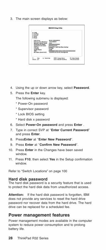
3. The main screen displays as below:
4. Using the up or down arrow key, select Password.
5. Press the Enter key.
The following submenu is displayed:
* Power-On password
* Supervisor password
* Lock BIOS setting
* Hard disk x password
6. Select Power-On password and press Enter .
7. Type in correct SVP at ″Enter Current Password″and press Enter.
8. PressEnter at ″Enter New Password″.
9. Press Enter at ″Confirm New Password″.
10. Press Enter in the Changes have been savedwindow.
11. Press F10; then select Yes in the Setup confirmationwindow.
Refer to “Switch Locations” on page 100
Hard disk passwordThe hard disk password is a security feature that is usedto protect the hard disk data from unauthorized access.
Attention: If the hard disk password is forgotten, IBMdoes not provide any services to reset the hard drivepassword nor recover data from the hard drive. The harddrive can be replaced for a scheduled fee.
Power management featuresPower management modes are available in the computersystem to reduce power consumption and to prolongbattery life.
28 ThinkPad R32 Series

Suspend modeWhen in standby mode, the following occurs:
v The LCD backlight turns off.
v The hard disk motor either spins down or stops(controlled by OS).
v Suspend LED turns on.
Events that cause the computer to enter standby mode:
Note: These events depend on the Power button, Sleepbutton and Lid settings (options set to standbymode) in the ″Advanced″ page of the ″PowerManagement Properties″ screen.
v Standby requested by the Sleep button (Fn+F4)
v Standby requested by the power button
v Standby requested by closing the lid.
Events that cause the computer to exit standby mode:
v RTC alarm
v Power-on switch is operated
v Fn key is pressed
v The LCD is opened (if the system entered standbymode from closing the lid).
Note: This is true if When I close the lid of myportable computer: is set to Standby in the″Advanced″ page of the ″Power ManagementProperties″ screen.
v An embedded modem signals the modem ring indicator
v The battery power is at a critical level.
Display off modeWhen in display off mode, the following occur:
v The LCD backlight turns off.
Events that cause the computer to enter display off mode:
v Hotkey : Fn+F3
Events that cause the computer to exit display off mode:
v Anykey or mouse operation
Hibernation modeWhen in hibernation mode, the following occurs:
v The system status, RAM, VRAM, and setup data arestored on the hard disk.
v The system is powered off.
Events that cause the computer to enter hibernation mode:
MT 2658/2659/2677 29

Note: These events depend on the Power button, Sleepbutton and Lid settings (options set to hibernatemode) in the ″Advanced″ page of the ″PowerManagement Properties″ screen.
v Hibernation requested by the Sleep button (Fn+F4) or(Fn+F12)
v Hibernation requested by the power button
v Hibernation requested by closing the lid.
Events that cause the computer to exit hibernation mode:
v RTC alarm
v Power-on switch is operated
v WOL (wake on Lan)
When power is turned on, the hibernation history in theboot record on the hard disk is recognized and the systemstatus is restored from the hard disk to resume operation.
Fn key combinationsThe following table shows the Fn key and function keycombinations and their corresponding functions. Some ofthe keys do not work if proper device drivers and utilitiesare not installed.
Fn key Function
Fn+F3 Display off
Fn+F4 Sleep button
Fn+F7 Switch display output location.
Fn+F8 Display expansion
Fn+F12 Hibernation
Fn+PageUp Thinkpad light
Fn+Home Brightness up
Fn+End Brightness down
Product recovery program
Restoring the Pre-installed SoftwareTo restore the pre-installed software, you can use eitherthe Product Recovery program or a Recovery CD. TheProduct Recovery program is in a section of the hard diskdrive (the Service Partition) that is not displayed byWindows Explorer. Use the Recovery CD if it was providedwith the computer.
Note: The recovery process might take up to 2 hours.
To use the Product Recovery program to restore thepre-installed software, do the following:
30 ThinkPad R32 Series

1. Save all files and shut down the desktop.
2. Turn off the computer.
3. Turn on the computer. Quickly press F11 when thismessage is displayed on the screen: ...″To start theProduct Recovery program, press F11″ .....Thismessage is displayed for only a few seconds.
Note: If this message does not appear, you can use aRecovery Repair diskette to get access to theProduct Recovery program.(see“Creating aRecovery Repair diskette” on page 32 forinstructions for making the Recovery Repairdiskette)
4. From the list displayed on the screen, select theoperating system you want to recover.
5. Select the recovery options you want, and follow theinstructions on the screen.
Creating the Service PartitionTo create Service Partition and install the preloadedsystem from Recovery CD, do the following;
To create Service Partition [SP]:
1. Erase all partitions on the hard-disk drive usingFDISK or similar application.
2. Boot with Recovery CD (and boot diskette if required).
3. A menu will appear stating ″Your computeroriginally included a Product Recovery program ...Reinstall the Product Recovery Program? (Y/N) []″.}.
Note: If the hard-disk drive contains any partitions,you will not receive this menu - go to step 1.
4. Enter ″Y″ and Service Partition will be created andloaded with D2D files.
Note: If you do not want to create Service Partition,press ″N″ , and the d then go to step 8.
5. Press ″Enter″ at next window to continue.
* Service Partition will be created. System willautomatically reboot during this process.
* Recovery process will copy some files to the ServicePartition, PKUNZIP others
* Follow prompts - you may be prompted to changeCDs.
* System will reboot when complete, continue to step6 to install preloaded system.
Install preloaded system from CD:
6. Boot with Recovery CD (and boot diskette if required)
MT 2658/2659/2677 31
7. If the hard-disk drive is blank, a menu will appearstating ″Your computer originally included aProduct Recovery program ... Reinstall theProduct Recovery Program? (Y/N) [ ]″.
* To install Service Partition, go to step 4.
* To preload hard-disk drive without installing ServicePartition, press ″N″.
8. If a menu appears asking which operating system toinstall, highlight proper operating system and press″″ENTER″.
9. A menu will appear stating ″Full Recovery:″. Press″″ENTER″ to select.
10. Enter ″Y″ at the three windows which follow.
11. Follow prompts to complete Recovery.
Creating a Recovery Repair disketteThe Recovery Repair diskette is used to recover theprompt that is needed to access the Product Recoveryprogram, if the prompt does not appear. Make a RecoveryRepair diskette and save it for future use.
To make a Recovery Repair diskette:
1. Shut down and turn off the computer.
2. Attach the external diskette drive to the computer.
3. At the prompt, pressF11. (The option to pressF11appears for only a few seconds. You must press F11quickly.) The Product Recovery program main menuappears.
4. If you are using Windows 2000 Professional, you willbe prompted to select the appropriate operating systemsetting. This menu does not appear for Windows 98SE.
5. Select System Utilities from the main menu. PressEnter.
6. Select Create a Recovery Repair diskette. Press Enter.
7. Follow the on-screen instructions.
8. When the process is completed, label the diskette asthe Recovery Repair diskette and save it for future use.
To use the Recovery Repair diskette:
1. Shut down and turn off the computer.
2. Attach the external diskette drive to the computer.
3. Insert the Recovery Repair diskette into the drive; thenturn on the computer.
4. Follow the on-screen instructions.
32 ThinkPad R32 Series

Flash BIOSPlease do the following to update BIOS.
To update BIOS:
1. Prepare the System Program Service Diskette (SPSD)
Save 1MUDXXUS.DSK file to C:\SPSD
Note: XXrepresents for the version of BIOS.
2. Boot the computer with SPSD.
a. Insert the created floppy diskette into floppydiskette drive before you turn on the computer.
b. Press the power button.
3. Follow the on-screen instructions after booting.
MT 2658/2659/2677 33

Checkout guide
Use the following procedure as a guide for computerproblems.
Note: The diagnostic tests are intended to test only IBMproducts. Non-IBM products, prototype cards, ormodified options can give false errors and invalidsystem responses.
1. Obtain the failing symptoms in as much detail aspossible.
2. Verify the symptoms by attempting to recreate thefailure by running the diagnostic test or by repeatingthe same operation.
Testing the computerThe ThinkPad computer has a test program calledPC-Doctor DOS (hereafter called PC-Doctor). You candetect errors by running the diagnostics test of PC-Doctor.This section is an overview on detecting the problem.Refer to “Product overview” on page 56 for details thatdepend on model-unique functions.
To run the test, do the following:
Note: In the following procedure, you can select an itemnot only with the arrow keys, but also with theTrackPoint. Instead of pressing Enter, you also canclick the left click button.
1. Insert the PC-Doctor DOS Disk #1into the diskettedrive; then power on the computer.
If the computer cannot be powered on, go to “Powersystems checkout” on page 36 and check the powersources.
If an error code appears, go to “Symptom-to-FRUIndex” on page 39.
Remove Disk #1 and Insert PC-Doctor DOS Disk #2into the diskette drive when prompted to do so.
The PC-Doctor main panel appears.
2. Select Diagnostics with the arrow keys, and pressEnter.
A pull-down menu appears:
Note: The pull-down menu differs depending on themodel.
3. Run the applicable function test.
4. Follow the instructions on the screen. If there is aproblem, PC-Doctor shows some messages.
34 ThinkPad R32 Series

5. Reseat the cable or connector of the detected FRUand run the test again.
If the error recurs, replace the FRU that caused theerror.
Note: With some FRUs, especially the system board,the problem may be caused by peripheralFRUs. Verify that each peripheral FRU, such asthe flexible cable, has no problem by doing thefollowing:
a. Replace each peripheral FRU one at a time,and run the test again.
b. If the peripheral FRUs have no problem,replace the main FRU itself.
To see the FRU structure of each model,refer to “Product overview” on page 56.
6. To exit the test, select Quit – Exit Diag.
To cancel the test, press Esc.
The following table lists the options on the test menu.
Diagnostics Interactive Tests
v Run Normal Test
v Run Quick Test
v CPU/Coprocessor
v Systemboard
v Video Adapter
v Serial Port
v Parallel Port
v Fixed Disks
v Diskette Drives
v Other Devices
v Wireless network controller(802.11b)
v Memory Test – Full
v Memory Test – Quick
v Audio Test
v Keyboard
v Video
v Internal Speaker
v Mouse
v Joystick Test
v Diskette Test
v System Load
v CD-ROM/DVD
v Stereo Speaker
Note: In Keyboard test within Interactive Tests, the Fn key isscanned only once. Each key should be pressed for at least 2seconds; otherwise, it cannot be sensed.
Related service informationPC-Doctor can detect the following system information:
Hardware Info:v System Configuration
v Memory Contents
MT 2658/2659/2677 35

v Physical Disk Drive
v Logical Disk Drive
v VGA Information
v IDE Drive Information
v PCI Information
v PNPISA Information
v SMBIOS Information
v FRU Information
v VESA LCD Information
Utility:v Run External Tests
v Surface Scan Hard Disk
v Benchmark System
v DOS Shell
v Tech Support Form
v Battery Rundown
v View Test Log
v Print Log
v Save Log
v Full Erase Hard Drive
v Quick Erase Hard Drive
Power systems checkoutTo verify the symptom of the power problem on thecomputer, do the following:
1. Power off the computer.
2. Remove the battery pack.
3. Connect the AC Adapter.
4. Check that power is supplied when you power on thecomputer.
5. Power off the computer.
6. Disconnect the AC Adapter and install the chargedbattery pack.
7. Check that power is supplied by the battery pack whenyou power on the computer.
If you suspect a power problem, refer the appropriatepower supply check listed below:
v “Checking the AC Adapter” on page 37
v “Checking operational charging” on page 37
v “Checking the Battery ASM” on page 38
36 ThinkPad R32 Series

Checking the AC AdapterYou care here because the computer fails only when theAC Adapter is used:
v If the power-on indicator does not turn on, check thepower cord of the AC Adapter for correct continuity andinstallation.
v If the operational charge does not work, go to “Checkingoperational charging”.
Unplug the AC Adapter cable from the computer andmeasure the output voltage at the plug of the AC Adaptercable. See the following figure:
Pin Voltage (V dc)
1 15.5 V. - 17.0 V.
2 Ground
If the voltage is not correct, replace the AC Adapter.
If the voltage is within the range, do the following:
v Replace the system board.
v If the problems still persist, go to “UndeterminedProblems” on page 54.
Note: An audible noise from the AC Adapter does notalways indicate a defect.
Checking operational chargingTo check operational charging, use a discharged batterypack (Battery ASM) or a Battery ASM that has less than50% of the total power remaining when installed in thecomputer.
Perform operational charging. If the battery status indicatoror icon does not turn on, remove the Battery ASM and let itreturn to room temperature. Reinstall the Battery ASM. Ifthe charge indicator or icon still does not turn on, replacethe Battery ASM.
If the charge indicator still does not turn on, replace thesystem board. Then reinstall the Battery ASM. If thereinstalled Battery ASM is not charged, go to the nextsection.
MT 2658/2659/2677 37

Checking the Battery ASM
Note: The Battery ASM may not be able to charged whenit is hot. In that case, remove it from the computerand leave it at room temperature for a while. After itcools down, reinstall it and recharge it.
Do the following:
1. Power off the computer.
2. Remove the battery pack and measure the voltagebetween battery terminals 1 (+) and 6 (-). See thefollowing figure.
12
3456
Terminal Pin No. Description
1 1 +0 to +16.8 V
2 2 Isolation slit
5 4 Thermistor
6 5 Battery –
Note: Signal lines, not used in these steps, are usedfor communications between the system and thebattery.
3. If the voltage is less than +14.4 V dc, the battery packhas been discharged. Note: Recharging will take atleast 3 hours, even if the indicator does not turn on. Ifthe voltage is still less than +14.4 V dc afterrecharging, replace the battery.
4. If the voltage is more than 9V for LiION, measure theresistance between battery terminals 5 and 6. Theresistance must be 4 to 30K�. If the resistance is notcorrect, replace the Battery ASM. If the resistance iscorrect, replace the system board.
38 ThinkPad R32 Series

Symptom-to-FRU Index
The Symptom-to-FRU Index lists the symptoms and errorsand the possible causes. The most likely cause is listedfirst.
Note: Perform the FRU replacement or actions in thesequence shown in the FRU/Action columns. If aFRU does not solve the problem, put the originalpart back in the computer. Do not replace anon-defective FRU.
This index can also be used to help you decide whichFRUs should be available when servicing a computer.
Numeric error codes show the errors detected in POST orsystem operation (runtime). In the following error codes, Xcan be any number.
If no codes are available, use narrative symptoms.
If the symptom, is not listed, go to “UndeterminedProblems” on page 54.
Note: For any IBM device not supported by the diagnosticcodes in this ThinkPad computer, see the manualfor that device.
Numeric Error Codes and Messages
ErrorCode
Message Meanings Comment orAction
0176 System Security-The system hasbeen tamperedwith
Security chip wasremoved andattached again.
1. Run IBMBIOS SetupUtility, andthen savecurrent settingby pressingF10.
2. SystemBoard.
0191 SystemSecurity-Invalidremote changerequested
Bad systemconfigurationchange requestdetected.
1. Run IBMBIOS SetupUtility, andthen savecurrent settingby pressingF10.
2. SystemBoard.
MT 2658/2659/2677 39

ErrorCode
Message Meanings Comment orAction
0192 SystemSecurity-IBMEmbeddedSecurity hardwaretamper detected.
Security chip IDmatching failed.
System Board
0197 Invalid RemoteChangeRequested
Reported when theCRC of requestpacket in EEPROMBlock #7 is wrong.
Recovery-Users need tosend thesystem backto the servicecenters.
0199 SystemSecurity-IBMSecurity passwordretry countexceeded
Systemadministratorpassword retryexpired (if failed 3times)
1. Run IBMBIOS SetupUtility, andthen savecurrent settingby pressingF10.
2. SystemBoard.
0200 Failure Fixed Disk Fixed disk is notworking or notconfigured properly.
Check to seeif fixed disk isattachedproperly. Runsetup. Findout if thefixed-disk typeis correctlyidentified.
0210 Stuck key Stuck key onkeyboard.
Runinteractivetests of thekeyboard andthe auxiliaryinput devices.
0211 Keyboard error Keyboard notworking.
Runinteractivetests of thekeyboard andthe auxiliaryinput devices.
0212 KeyboardController Falied
Keyboard ControllerFalied test. Mayrequire replacingkeyboard controller.
Runinteractivetests of thekeyboard andthe auxiliaryinput devices.
0213 Keyboard lockedUnlock key switch
Unlock the systemto proceed.
Runinteractivetests of thekeyboard andthe auxiliaryinput devices.
40 ThinkPad R32 Series

ErrorCode
Message Meanings Comment orAction
0220 Monitor type doesnot match CMOSRun SETUP
Monitor type notcorrectly identifiedis Setup.
Load SetupDefaults inIBM BIOSSetup Utility.
0230 Shadow RAMfailed at offset :nnnn
Shadow RAM failedat offset nnnn ofthe 64k block atwhich the error wasdetected.
System Board
0231 System RAMfailed at offset :nnnn
System RAM failedat offset nnnn of inthe 64k block atwhich the error wasdetected.
1. DIMM
2. SystemBoard
0232 Extended RAMFailed at offset :nnnn
Extended memorynot working or notconfigured properlyat offset nnnn,
1. DIMM
2. SystemBoard
0250 System battery isdead Replace andrun SETUP
The CMOS clockbattery indicatorshows the batteryis dead. Replacethe battery and runSetup toreconfigure thesystem.
Replace thebackupbattery andrun IBM BIOSSetup Utilityto reset thetime and date.
0251 System CMOSchecksumbad-defaultconfiguration
System CMOS hasbeen corrupted ormodified incorrectly,perhaps by anapplication programthat changes datastored in CMOS.The BIOS installedDefault SetupValues. If you donot want thesevalues, enter Setupand enter your ownvalues. If the errorpersists, check thesystem battery orcontact your dealer.
Replace thebackupbattery andrun IBM BIOSSetup Utilityto reset thetime and date.
*0260 System timer error The timer testfailed. Requiresrepair of systemboard.
1. Replacethe backupbattery andrun IBM BIOSSetup Utilityto reset thetime and date.
2. SystemBoard
MT 2658/2659/2677 41

ErrorCode
Message Meanings Comment orAction
0270 Real time clockerror
Real-Time Clockfails BIOShardware test. Mayrequire boardrepair.
1. Replacethe backupbattery andrun IBM BIOSSetup Utilityto reset thetime and date.
2. SystemBoard
0271 Check date andtime settings
BIOS found date ortime out of rangeand reset theReal-Time Clock.May require settinglegal date(1991–2099).
Run IBMBIOS SetupUtility to resetthe time anddate.
0280 Previous bootincomplete-Defaultconfiguration used
Previous POST didnot completesuccessfully. POSTloads default valuesand offers to runSetup. If the failurewas caused byincorrect valuesand they are notcorrected, the nextboot will likely fail.On system withcontrol of waitstates, improperSetup settings canalso teminatePOST and causethis error on thenext boot. RunSetup and verifythat wait-stateconfiguration iscorrect. This erroris cleared the nexttime the system isbooted.
IBMcustomizednot to displaythis message.
0281 Memory Sizefound by POSTdiffered fromCMOS
Memory size foundby POST differedfrom CMOS.
Load ″SetupDefault″ inIBM BIOSSetup Utility.
02B0 Diskette drive Aerror Diskettedrive B error
Drive A: or B: ispresent but fails theBIOS POSTdiskette tests.CHeck to see thatthe drive is definedwith the properdiskette type inSetup and that thediskette drive isattached corretly.
Load ″SetupDefault″ inIBM BIOSSetup Utility.
42 ThinkPad R32 Series

ErrorCode
Message Meanings Comment orAction
02B2 Incorrect Drive Atype — runSETUP
Type of floppy driveA: not correctlyidentified in Setup
Diskette Drive
02B3 Incorrect Drive Btype — runSETUP
Type of floppy driveB: not correctlyidentified in Setup
Diskette Drive
02D0 System cacheerror- Cachedisabled
RAM cache failedand BIOS disabledthe cache. On olderboards, check thecache jumpers. Youmay have toreplace that cache.See your dealer. Adisabled cacheslows systemperformanceconsiderably.
System Board
02F0: CPU ID: CPU socketnumber forMulti-Processorerror.
02F4: EISA CMOS notwriteable
ServerBIOS2 testerror: Cannot writeto EISA CMOS.
1. Load SetupDefaults inIBM BIOSSetup Utility.
2. Replacethe backupbattery
3. SystemBoard
02F5: DMA Test Failed ServerBIOS2 testerror: Cannot writeto extended DMA(Direct MemoryAccess) registers.
1. DIMM
2. SystemBoard
02F6: Software NMIFailed
ServerBIOS2 testerror: Cannotgenerate softwareNMI(Non-MaskableInterrupt).
1. DIMM
2. SystemBoard
02F7: Fail-Safe TimerNMI Failed
ServerBIOS2 testerror: Fail-SafeTimer takers toolong.
1. DIMM
2. SystemBoard
device AddressConflict
Address conflict forspecified device.
1. Load SetupDefaults inIBM BIOSSetup Utility.
2. Backupbattery
3. SystemBoard
MT 2658/2659/2677 43

ErrorCode
Message Meanings Comment orAction
Allocation Errorfor: device
Run ISA or EISAconfiguration Utilityto resolve resourceconflict for thespecified device.
1. Load SetupDefaults inIBM BIOSSetup Utility.
2. Backupbattery
3. SystemBoard
CD ROM Drive CD ROM Driveidentified.
Entering SETUP Starting Setupprogram
Failing Bits: nnnn The hex numbernnnn is a map ofthe bits at the RAMaddress whichfailed the memorytest. Each 1 (one)in the mapindicates a failedbit. See errors 230,231, or 232 abovefor offset addressof the failure inSystem,Extended,or Shadowmemory.
1. DIMM
2. SystemBoard
Fixed Disk n Fixed disk n (0–3)identified.
Invalid SystemConfiguration Data
Problem withNVRAM (CMOS)data.
1. DIMM
2. SystemBoard
I/O device IRQconflict
I/O device IRQconflict error.
1. Load SetupDefaults inIBM BIOSSetup Utility.
2. Backupbattery
3. SystemBoard
PS/2 Mouse BootSummary Screen:
PS/2 Mouseinstalled
nnnn kB ExtendedRAM Passed
Where nnnn is theamount of RAM inkilobytessuccessfully tested.
nnnn CacheSRAM Passed
Where nnnn is theamount of systemcache in kliobytessuccessfully tested.
44 ThinkPad R32 Series

ErrorCode
Message Meanings Comment orAction
nnnn kB ShadowRAM Passed
Where nnnn is theamount of shadowRAM in kilobytessuccessfully tested.
nnnn kB SystemRAM Passed
Where nnnn is theamount of systemRAM in kilobytessuccessfully tested.
One or more I2OBlock StorageDevices wereexcluded from theSetup Boot Menu
There was notenough room in theIPL table to displayall installed I2Oblock-storagedevices.
Operating systemnot found
Operating systemcannot be locatedon either drive A: ordrive C:. EnterSetup and see iffixed disk and driveA: are properlyidentified.
1. Check thatthe operatingsystem hasno failure andis installedcorrectly.
2. Enter theIBM BIOSSetup Utilityand seewhether thehard-diskdrive and thediskette driveare properlyidentified.
3. Reseat thehard-diskdrive.
4. Reinstallthe operatingsystem.
5. Diskettedrive.
6. Hard-diskdrive.
7. Systemboard.
MT 2658/2659/2677 45

ErrorCode
Message Meanings Comment orAction
Parity Check 1nnnn
Parity error found inthe system bus.BIOS attempts tolocate the addressand display it onthe screen. If itcannot locate theaddress, it displays????. Parity is amethod forchecking errors inbinary data. A parityerror indicates thatsome data hasbeen corrupted.
Parity Check 2nnnn
Parity error found inthe I/O bus. BIOSattempts to locatethe address anddisplay it on thescreen. If it cannotlocate the address,it displays ????.
PS/2 Mouse: PS/2 mouseidentified.
System BIOSshadowed
System BIOScopied to shadowRAM.
UMB upper limitsegment address:nnnn
Displays theaddress nnnn ofthe upper limit ofUpper MemoryBlocks, indicatingreleased segmentsof the BIOS whichcan be reclaimedby a virtual memorymanager.
Video BIOSshadowed
Video BIOSsuccessfully copiedto shadow RAM
0175 Bad CRC1, stopPOST task
EEPROM CRC1 isnot correct (block#6).
Replaceplanar.
0187 EAIA data accesserror
EEPROM access(read or write) isfailed.
System Board
0188 Invalid RFIDSerializationInformation Areaor Bad CRC2
EEPROMchecksum is notcorrect (block#0,1).EEPROMCRC2 is not correct(block #6).
Replaceplanar. Boxserial numberneeds to bereinstalled.
0189 Invalid RFIDConfigurationInformation Area
EEPROMchecksum is notcorrect (block #4,5).
Replaceplanar. UUIDneeds to bereinstalled.
46 ThinkPad R32 Series

ErrorCode
Message Meanings Comment orAction
0190 Critical low-batteryerror
Critical Low Battery. Charge theBattery Pack.
0193 RF antenna hadbeen removed
RFID antenna hasbeen removed,which was onceinstalled.
RFID modelonly.
0194 The computer iscarried throughthe security gate
The computer iscarried through thesecurity gate (portalgate).
RFID modelonly.
1801 Unsupporteddocking station isattached - Poweroff and removethe dockingstation
Attached dockingstation is notsupported by theproduct.
Fan error Cooling fan isfailing.
FAN
Do you want abortresume fromhibernation?(Y/N)Systemmemory removed,press F3 to poweroff system andrestore memorychip, press F4 tonormal boot
DIMM is removedduring hibernationstate.
1. Restore thesystemconfigurationto what it wasbefore thecomputerenteredhibernationmode.
2. If thememory sizehas beenchanged,re-create thehibernationfile.
Docking station isremoved or its IDis different,pressF3 to power offsystem andrestorecorrectdockingstation, press F4to normal boot.
Undocked duringhibernation state, ordocked to anotherdocking stationduring hibernationstate.
No errorappearswhen; undock-> hibernation-> dock ->wakeup. Thedocking isconfigured byOS.
Beep Symptoms
ID Usage Description
0 Reserved stop
1 Critical low batteryalarm
pi (1250Hz) for 500ms po(315Hz) for 500ms pi for500ms po for 500ms pifor 500ms po for 500ms
MT 2658/2659/2677 47

ID Usage Description
2 Low battery alarm(yellow—> Red)
pi (1250Hz) for 125ms nosound for 125ms pi(1250Hz) for 125ms
3 Suspend beep pi (1250Hz) for 125ms
4 Partial suspendbeep
pi (1250Hz) for 250ms po(315Hz) for 250ms
5 Resume beep pi (1250Hz) for 125ms
6 DC in/ out beep pi (1760Hz) for 125ms pi(1400Hz) for 125ms
7 Power off beep pi (1760Hz) for 250ms
8 Power off alarm pi (1760Hz) for 125ms nosound for 125ms
pi (1760Hz) for 125ms
9 No HDD alarm pi (1760Hz) for 125ms nosound for 125ms
pi (1760Hz) for 125ms nosound for 125ms
pi (1760Hz) for 125ms
10 Dead pi (1760Hz) for 4000ms
11 880Hz beep pu (880Hz) for 125ms
12 315Hz beep po (315Hz) for 125ms
13 Two 315Hz beep po (315Hz) for 125ms nosound for 125ms
po (315Hz) for 125ms
14 Three 315Hz beep po (315Hz) for 125ms nosound for 125ms
po (315Hz) for 125ms nosound for 125ms
po (315Hz) for 125ms
15 Bay alarm pi (1760Hz) for 125ms nosound for 125ms
pi (1760Hz) for 125ms nosound for 125ms
pi (1760Hz) for 125ms
48 ThinkPad R32 Series

LCD-Related Symptoms
LCD FRU Replacement NoticeThe TFT LCD for the computer contains manythin-film transistors (TFTs). A small number ofmissing, discolored, or lighted dots (on all the time)is characteristic of TFT LCD technology, butexcessive pixel problems can cause viewingconcerns. The LCD should be replaced if thenumber of missing, discolored, or lighted dots in anybackground is:
v XGA : 8 or more bright dots, 8 or more dark dots,or a total of 9 or more bright and dark dots.
Symptom/Error FRU/Action in Sequence
LCD backlight does notwork.
LCD is too dark.
LCD brightness cannotbe adjusted.
v Keyboard (if contrast andbrightness function keys do notwork)
v Reseat LCD connector
v Check LCD inverter ID
v LCD Cable ASM
v LCD Inverter/LED board(13.3″/14.1″)
v LCD
v System board
Unreadable LCD screen.
Missing pixels incharacters.
Abnormal screen
Wrong color displayed.
v Reseat LCD connector
v Check LCD inverter ID
v LCD Cable ASM
v LCD Inverter/LED board(13.3″/14.1″)
v LCD
v System board
LCD has extra horizontalor vertical linesdisplayed.
v Check LCD inverter ID
v LCD Cable ASM
v LCD Inverter/LED board(13.3″/14.1″)
v LCD
v System board
MT 2658/2659/2677 49

Keyboard/TrackPoint-RelatedSymptoms
Symptom/Error FRU/Action in Sequence
Keyboard (one or morekeys) doesn’t work.
v Go to “FRU tests” on page 60.
v Reseat keyboard cable.
v Keyboard
v System board
TrackPoint does notwork.
v Go to “FRU tests” on page 60.
v Reseat keyboard cable.
v Keyboard
v System board
Indicator-Related Symptoms
Symptom/Error FRU/Action in Sequence
Indicator incorrectlyremains off or on, butsystem runs correctly.
v Reseat Inveter/LED board(13.3″/14.1″)
v Inveter/LED board (13.3″/14.1″)
v System board
v Coaxial cable
Power-Related Symptoms
Symptom/Error FRU/Action in Sequence
Power shuts down duringoperation.
v Go to “Power systems checkout” onpage 36.
v AC Adapter
v Battery assembly
v Keyboard
v System board
The system doesn’tpower on.
v Go to “Power systems checkout” onpage 36.
v AC Adapter
v Battery assembly
v Keyboard
v System board
The system doesn’tpower off.
v Go to “Power systems checkout” onpage 36.
v Hold and press the power switchfor more than 4 seconds.
v Keyboard
v System board
50 ThinkPad R32 Series
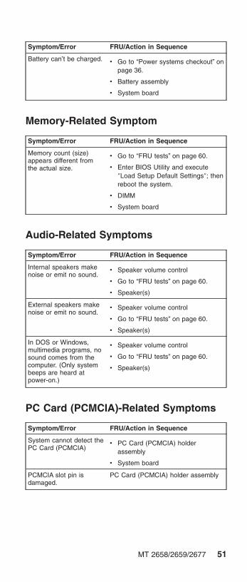
Symptom/Error FRU/Action in Sequence
Battery can’t be charged. v Go to “Power systems checkout” onpage 36.
v Battery assembly
v System board
Memory-Related Symptom
Symptom/Error FRU/Action in Sequence
Memory count (size)appears different fromthe actual size.
v Go to “FRU tests” on page 60.
v Enter BIOS Utility and execute″Load Setup Default Settings″; thenreboot the system.
v DIMM
v System board
Audio-Related Symptoms
Symptom/Error FRU/Action in Sequence
Internal speakers makenoise or emit no sound.
v Speaker volume control
v Go to “FRU tests” on page 60.
v Speaker(s)
External speakers makenoise or emit no sound.
v Speaker volume control
v Go to “FRU tests” on page 60.
v Speaker(s)
In DOS or Windows,multimedia programs, nosound comes from thecomputer. (Only systembeeps are heard atpower-on.)
v Speaker volume control
v Go to “FRU tests” on page 60.
v Speaker(s)
PC Card (PCMCIA)-Related Symptoms
Symptom/Error FRU/Action in Sequence
System cannot detect thePC Card (PCMCIA)
v PC Card (PCMCIA) holderassembly
v System board
PCMCIA slot pin isdamaged.
PC Card (PCMCIA) holder assembly
MT 2658/2659/2677 51

Power Management-Related Symptoms
Symptom/Error FRU/Action in Sequence
The system doesn’t enterhibernation mode.
v Go to “Hibernation mode” onpage 29.
v Boot an operating system andpress Fn+F12 and see if thecomputer enters hibernation mode.
v Keyboard
v Hard disk drive connector
v Hard disk drive
v System board
The system doesn’tresume from hibernationmode.
v Go to “Hibernation mode” onpage 29.
v Hard disk drive connector
v Hard disk drive
v System board
The system doesn’t enterinto or resume fromsleep mode after closingthe LCD.
v Lid switch
v System board
v Lid close action in the poweroperation properties of the OS
System configurationdoes not match theinstalled devices.
v Enter BIOS Utility and execute″Load Setup Default Settings″; thenreboot the system.
v Reseat Hard disk/diskette/CD-ROMdrive connector.
System hangsintermittently.
v Reseat hard disk/diskette/CD-ROMdrive connector.
v Fan ASM (go to “FRU tests” onpage 60).
v System board
Peripheral-Device-Related Symptoms
Symptom/Error FRU/Action in Sequence
External display does notwork correctly.
v Both display mode, press Fn+F7.
v System board
Printer problems. v Run printer self-test.
v Printer driver
v Printer cable
v Ensure that ″Parallel Port″ in the″Config sub-menu″ menu of theBIOS Utility is correctly set.
v System board
52 ThinkPad R32 Series

Symptom/Error FRU/Action in Sequence
Parallel port deviceproblems.
v Device driver
v Device cable
v Device
v Ensure that ″Parallel Port″ in the″Config sub-menu″ menu of theBIOS Utility is correctly set.
v System board
Modem-Related Symptom
Symptom/Error FRU/Action in Sequence
Internal modem does notwork correctly
v Go to “FRU tests” on page 60.
v Modem connector
v Modem board
v System board
Operating System-Related Symptom
Symptom/Error FRU/Action in Sequence
Operating system notfound
v Check that the operating systemhas no failure and is installedcorrectly.
v Check the Boot device list in thestartup/Boot sub-menu is enabledon each bootable device.
v Enter IBM BIOS Setup Utility andsee whether the hard disk driveand the diskette drive are properlyidentified.
v Reseat the hard disk drive.
v Reinstall the operating system.
v Diskette drive
v Hard disk drive
v System board
Intermittent ProblemsIntermittent system hang problems can be caused by avariety of reasons that have nothing to do with a hardwaredefect, such as cosmic radiation, electronic discharge, orsoftware errors. FRU replacement should only beconsidered when a recurring problem exists.
When analyzing on intermittent problem, do the following:
MT 2658/2659/2677 53

1. Run the diagnostic test for the system board at least10 times.
2. If no error is detected, do not replace any FRUs.
3. If any error is detected, replace the FRU. Rerun thetest to verify that there are no more errors.
Undetermined ProblemsThe diagnostic tests did not identify which adapter ordevice failed, which installed devices are incorrect, whethera short circuit is suspected, or whether the system isinoperative. Follow the procedures below to isolate thefailing FRU.
Verify that the power supply being used at the time of thefailure is operating correctly.
1. Power off the computer.
2. Check the cables, wires, and connectors for shortcircuits and open circuits. Visually check them fordamage. If any problems are found, replace the FRU.
3. Remove or disconnect all of the following devices:
v Non-IBM devices
v Printer, external mouse & keyboard, and otherexternal devices
v Battery pack
v Hard disk drive
v CD-ROM drive/Diskette drive (optional)
v PC Card (PCMCIA)
4. Power on the computer.
5. Determine if the problem has changed.
6. If the problem does not occur again, reconnect theremoved devices one at a time until you find the failingFRU.
7. If the problem remains, replace the following FRUs oneat a time. Do not replace a non-defective FRU.
v Hard disk drive connection board
v LCD assembly
v System board
54 ThinkPad R32 Series

ThinkPad R32 Series Part I
This section applies to the following models: 2658–F2X,2658–DBX, 2658–DDX, 2658–DEX, 2658–DSX,2658–DTX, 2658–G4X, 2658–G5X, 2658–G6X, 2658–G7X,2658–G8X, 2658–G9X, 2658–GAX, 2658–GBX,2658–GCX, 2658–GDX, 2658–GEX, 2658–GFX,2658–GGX, 2658–GHX, 2658–GJX, 2658–GKX,2658–GLX.
MT 2658/2659/2677 55

Product overviewThe following shows an overview of the system features.
Feature Description
Processor Intel Pentium-4M–1.6GHz/1.7GHz/1.8GHz Intel
Chip set Intel Brookdale (845MP)
Bus architecture Host bus 64 bits 266 MHz, PCI 32bits/33 MHz, ISA 16 bits/8.33MHz,PCMCIA 16 bits/33 MHz, Cardbus 32bits/32 MHz
System memory Two DDR DIMM Slots support 128MB,256MB, and 512MB DIMM card, up toMax. 1GB
Maximum frequency: PC 266 MHz
Maximum size: 1024 MB
CMOS RAM 256 bytes
Video ATI M6C graphics integrated V-RAMchip (8MB/16MB)
14.1– inch, 32 bit true colors,1024X768 pixel TFT XGA color LCD
Video memory 8/16MB V-RAM in video chip
LCD(Bright Ctrl) 13.3″ TFT (XGA)/ 14.1″ TFT (XGA)(KBD)
Audio AC97 audio based on the Intel ICH3AC link DMA engine
16– bit audio
Internal stereo speakers
Floppy Diskette drive(By model)
USB FDD External 1.44MB, 3.5 inchfloppy drive via USB interface(Bootable)
Hard disk drive-Upgradable
20GB, 30GB or 40GB, 2.5–inch9.5mm height, E-IDE interface
Ultrabay Plus 24X CD/ 8X DVD/ 8X, 4X, 24X MaxCD-RW/ CD-RW- DVD (Combo)/ BayBattery support, NEATS
Modem V.90 Soft modem (MDC or Livingstonemodem) Integrated CDC soft modemon the Intel ICH3 AC link DMA engine56 Kbps Data /Fax Modem.
Ethernet Intel Ethernet LOM
IEEE 1394 (on planar) On planar (Pop/ Depop) TiTSB43AB21 1394 controller on board
IEEE 1394.a 4–pin connector –nocable power 100 Mbps, 200 Mbps and400 Mbps.
CDC One CDC slot (MDC)
56 ThinkPad R32 Series

Feature Description
Mini-PCI One Mini-PCI slot (802. 11b-ModemCombo)
Antenna (By Model) Yes
PC Card (PCMCIA) T2x1 or T3x1 (Cardbus w/o ZV Port)Two Type I/II or oneType III
ThinkLight Yes
IR Yes
I/O ports External monitor
Parallel
CRT
Two USB
Headphone
Mic-in
Speaker-out
Telephone (RJ11)
LAN (RJ45)
TV-out (S-Video)
Docking (for port Replicator)
DC-in
IEEE 1394 port (IEEE 1394 modeonly)
Security chip support TCPA Security
Power 72–Watt AC Adapter
8–cell Li-Ion Intelligent Battery Pack
BIOS IBM BIOS
Status indicatorsThe system-status indicators on the computer show thecurrent status of your computer by their on or off statesand colors (green and orange). Each indicator is identifiedwith a symbol. The following shows the location and the
MT 2658/2659/2677 57
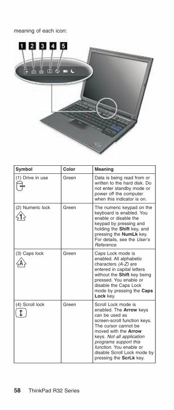
meaning of each icon:
Symbol Color Meaning
(1) Drive in use Green Data is being read from orwritten to the hard disk. Donot enter standby mode orpower off the computerwhen this indicator is on.
(2) Numeric lock Green The numeric keypad on thekeyboard is enabled. Youenable or disable thekeypad by pressing andholding the Shift key, andpressing the NumLk key.For details, see the User’sReference.
(3) Caps lock Green Caps Lock mode isenabled. All alphabeticcharacters (A-Z) areentered in capital letterswithout the Shift key beingpressed. You enable ordisable the Caps Lockmode by pressing the CapsLock key.
(4) Scroll lock Green Scroll Lock mode isenabled. The Arrow keyscan be used asscreen-scroll function keys.The cursor cannot bemoved with the Arrowkeys. Not all applicationprograms support thisfunction. You enable ordisable Scroll Lock mode bypressing the ScrLk key.
58 ThinkPad R32 Series

Symbol Color Meaning
(5) Power on Green The computer isoperational. This indicator ison when the computer ison.
(6) Battery status Green Enough battery powerremains for operation.
Blinkinggreen
The battery power chargesup to 80% full power
Blinkingorange
The battery pack needs tobe charged
Orange The battery pack is beingcharged.
(7) Standby mode Green The computer is in standbymode
Symbol Color Meaning
(1) Battery status Green Enough battery powerremains for operation.
Blinkinggreen
The battery power chargesup to 80% full power
Blinkingorange
The battery pack needs tobe charged
Orange The battery pack is beingcharged.
(2) Standby mode Green The computer is in standbymode
MT 2658/2659/2677 59

FRU testsThe following table shows the applicable test for each FRUusing PC-Doctor.
FRU Applicable test
System board 1. CPU/Coprocessor (Diagnostics)
2. System board (Diagnostics)
Power Battery (Diagnostics)
LCD unit 1. Video Adapter (Diagnostics)
2. Video (Interactive Tests)
Modem 1. Make sure the modem set upcorrectly.
2. Replacing the modem jack andmodem card one at a time, run themodem tests in Other Devices(Diagnostics)
Audio Internal Speaker (Interactive Tests)
Stereo Speaker (Interactive Tests)
Speaker System beeper: Internal Speaker(Interactive Tests)
PC Card slots System board (Diagnostics)
Keyboard 1. Keyboard (Diagnostics)
2. Keyboard (Interactive Tests)
TrackPont or Pointingdevice
If the TrackPoint does not work, see if anexternal PS/2 mouse is connected to themouse/keyboard connector and removeit. The TrackPoint is automaticallydisabled if an external PS/2 mouse isattached. Check also if the TrackPointdriver is correctly installed by accessingWindows Device Manager via the Systemicon in the Control Panel.
After you use the TrackPoint, the pointerdrifts on the screen for a short time. Thisself-acting pointer movement can occurwhen a slight, steady pressure is appliedto the TrackPoint pointer. This symptomis not a hardware problem. No serviceactions are necessary if the pointermovement stops in a short period of time.
If this does not correct the TrackPointproblem, continue with the following:Mouse (Interactive Tests).
Hard disk drive Fixed Disks (Diagnostics)
CD-ROM drive CD-ROM, DVD, CD-RW, DVD/CD-RW(Interactive Tests)
60 ThinkPad R32 Series

FRU Applicable test
Memory 1. If a DIMM is installed, remove it andrun Memory Test-Quick (Diagnostics)
2. If the problem does not recur, replacethe DIMM and run the test again.
3. If the test does not detect the error,run Memory Test-Full (Diagnostics)
Fan 1. Power on system and check the airturbulence at the louver at the rear ofthe computer.
2. Run the fan test in Other Devices(Diagnostics).
MT 2658/2659/2677 61

FRU removals and replacementsThis section contains information about removals andreplacements.
v Do not damage any parts. Only certified and trainedpersonnel should service the computer.
v The arrows in this section show the direction ofmovement to remove a FRU, or to turn a screw torelease the FRU. The arrows are marked in numericorder, in square callout, to show the correct sequence ofremoval.
v Any FRUs that must be removed before removing thefailing FRU are listed at the top of the page.
v To replace a FRU, reverse the removal procedure andfollow any notes that pertain to replacement. See“Locations” on page 98 for internal cable connectionsand arrangement information.
v When replacing a FRU, use the correct screw size, asshown in the procedure.
Safety Notice 1Translations in ″Safety Notices (Multi-lingualTranslations)″ section: Before the computer ispowered-on after FRU replacement, make sure allscrews, springs, or other small parts are in placeand are not left loose inside the computer. Verifythis by shaking the computer and listening forrattling sounds. Metallic parts or metal flakes cancause electrical shorts.
Safety Notice 3Translations in ″Safety Notices (Multi-lingualTranslations)″ section: The battery pack containssmall amounts of nickel. Do not disassemble it,throw it into fire or water, or short-circuit it. Disposeof the battery pack as required by local ordinancesor regulations. Use only the battery in theappropriate parts listing when replacing the batterypack. Use of an incorrect battery can result inignition or explosion of the battery.
62 ThinkPad R32 Series

Safety Notice 8Translations in ″Safety Notices (Multi-lingualTranslations)″ section: Before removing any FRU,power-off the computer, unplug all power cords fromelectrical outlets, remove the battery pack, thendisconnect any interconnecting cables.
Attention: The system board is sensitive and can bedamaged by electronic discharge. Establish personalgrounding by touching a ground point with one hand beforetouching these units.
An electrostatic discharge (ESD) strap (P/N: 6405959)must be used to establish personal grounding.
Note: When disassembling the computer, pleasefollow the numerical and alphabetical orderssuch as 1a, 1b, 1c, 1d, 2, 3, 4. Please note thatwhen you assemble the computer, the sequencemarked in number and alphabets should berevervsed, for instance, 4, 3, 2, 1d, 1c, 1b, 1a.
1010 Battery Disassembly
21 2
WarningBattery packs are capable of delivering highcurrents for a significant amount of time. Do notshort the battery terminals.
CAUTION:Danger of explosion if battery is incorrectly replaced.Replace only with the same or equivalent typerecommended by the manufacturer. Dispose of usedbatteries according to the manufacturer’s instructions.
MT 2658/2659/2677 63
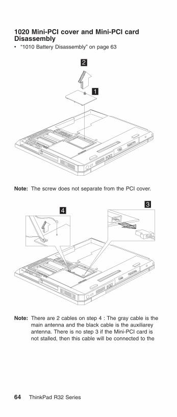
1020 Mini-PCI cover and Mini-PCI cardDisassemblyv “1010 Battery Disassembly” on page 63
1
2
Note: The screw does not separate from the PCI cover.
33
4
Note: There are 2 cables on step 4 : The gray cable is themain antenna and the black cable is the auxiliareyantenna. There is no step 3 if the Mini-PCI card isnot stalled, then this cable will be connected to the
64 ThinkPad R32 Series
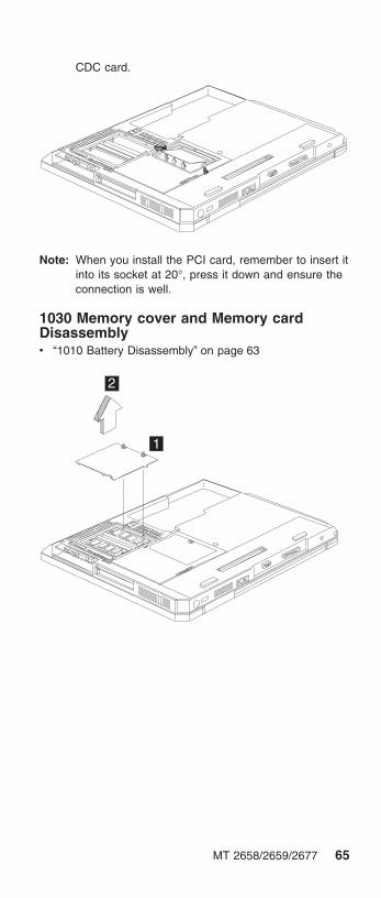
CDC card.
Note: When you install the PCI card, remember to insert itinto its socket at 20°, press it down and ensure theconnection is well.
1030 Memory cover and Memory cardDisassemblyv “1010 Battery Disassembly” on page 63
1
2
MT 2658/2659/2677 65

Note: The screws do not separate from the memorycover.
1
2
To install the memory card:
With the notched end of the memory card toward the rightside of the socket, insert the memory card, at an angle ofapproximately 20°, into the socket; then press it firmly.Pivot the memory card until it snaps into place.
Side View
1040 Hard Disk Drive Disassemblyv “1010 Battery Disassembly” on page 63
66 ThinkPad R32 Series

1
2
Step Size (Quantity) Color Torque
1 M3 x L3.5 (1) Black 3.2 kgf-cm
WarningDo not drop or apply any shock to the hard diskdrive. The hard disk drive is sensitive to physicalshock. Incorrect handling can cause damage andpermanent loss of data on the drive.
Before removing the drive, have the user make abackup copy of all the information on the drive ifpossible.
Never remove the drive while the system isoperating or is in suspend mode.
1050 Hard Disk Drive Cover Disassemblyv “1010 Battery Disassembly” on page 63
1
1060 CD-ROM Disassemblyv “1010 Battery Disassembly” on page 63
MT 2658/2659/2677 67

1
2
3
1070 Keyboard Disassemblyv “1010 Battery Disassembly” on page 63
1a 1b
Step Size (Quantity) Color Torque
1 M2.5 x L10 (2) Black 3.2 kgf-cm
68 ThinkPad R32 Series
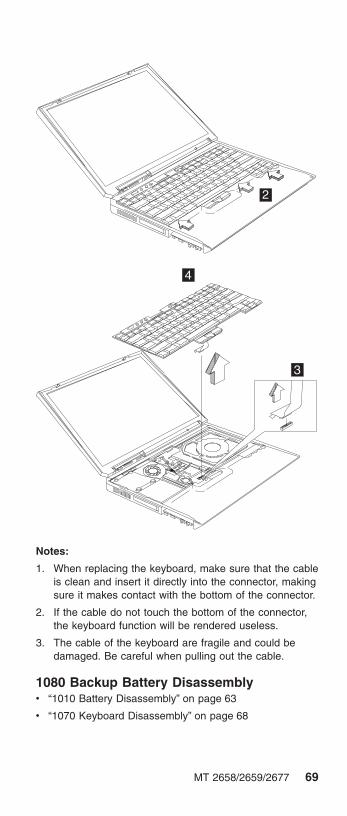
2
3
4
Notes:
1. When replacing the keyboard, make sure that the cableis clean and insert it directly into the connector, makingsure it makes contact with the bottom of the connector.
2. If the cable do not touch the bottom of the connector,the keyboard function will be rendered useless.
3. The cable of the keyboard are fragile and could bedamaged. Be careful when pulling out the cable.
1080 Backup Battery Disassemblyv “1010 Battery Disassembly” on page 63
v “1070 Keyboard Disassembly” on page 68
MT 2658/2659/2677 69

1
2
CAUTION:Danger of explosion if battery is incorrectly replaced.Replace only with the same or equivalent typerecommended by the manufacturer. Dispose of usedbatteries according to manufacturer’s instruction.
Safety Notice 4Translation in ″Safety Notices: Multi-lingualTranslations″ section: The backup battery is alithium battery and can cause a fire, an explosion, orsevere burns. Do not recharge it, remove itspolarized connector, disassemble it, heat it above100°C (212°F), incinerate it, or expose its cellcontents to water. Dispose of the battery as requiredby local ordinances or regulations. Use of anincorrect battery can result in ignition or explosion ofthe battery. Replacement batteries can be orderedfrom IBM or IBM Authorized Dealers.
1090 Safety Cover Disassemblyv “1010 Battery Disassembly” on page 63
v “1070 Keyboard Disassembly” on page 68
70 ThinkPad R32 Series

1
1100 Middle Cover Disassemblyv “1010 Battery Disassembly” on page 63
v “1070 Keyboard Disassembly” on page 68
1
2
MT 2658/2659/2677 71

4
Step Size (Quantity) Color Torque
2 M2.5 x L10 (1) Black 3.2 kgf-cm
4 M2.5 x L5 (1) Silver 2.5 kgf-cm
1110 CDC Cover Disassemblyv “1010 Battery Disassembly” on page 63
v “1020 Mini-PCI cover and Mini-PCI card Disassembly”on page 64
v “1070 Keyboard Disassembly” on page 68
v “1100 Middle Cover Disassembly” on page 71
1
Step Size (Quantity) Color Torque
1 M2.5 x L5 (1) Silver 2.5 kgf-cm
72 ThinkPad R32 Series

2
3
Notes:
1. If the Thinkpad R32 products are equipped with theMini-PCI card, then the CDC modem card will not beinstalled. The procedure of ″cdc-card″ referred aboveshould be skipped.
1120 Modem Cable Disassembly (WithoutCDC Modem Card)v “1010 Battery Disassembly” on page 63
v “1020 Mini-PCI cover and Mini-PCI card Disassembly”on page 64
v “1070 Keyboard Disassembly” on page 68
v “1100 Middle Cover Disassembly” on page 71
v “1110 CDC Cover Disassembly” on page 72
1
2
Notes:
1. If the Thinkpad R32 products are equipped with theMini-PCI card, the CDC modem card will not be
MT 2658/2659/2677 73

installed. The modem cable will then be connected tothe Mini-PCI card. Refer to ″Mini-PCI card″disassembly procedure to disconnect the modemcable.
1130 Modem Cable Disassembly (With CDCModem Card)v “1010 Battery Disassembly” on page 63
v “1070 Keyboard Disassembly” on page 68
v “1100 Middle Cover Disassembly” on page 71
v “1110 CDC Cover Disassembly” on page 72
1
Notes:
1. If the Thinkpad R32 products are equipped with theCDC modem card, the wireless LAN board will not beinstalled. The modem cable will then be connected tothe CDC modem card. Refer to ″CDC modem card″disassembly procedure to disconnect the modemcable.
1140 Auxiliary Antenna Disassemblyv “1010 Battery Disassembly” on page 63
v “1020 Mini-PCI cover and Mini-PCI card Disassembly”on page 64
v “1070 Keyboard Disassembly” on page 68
v “1100 Middle Cover Disassembly” on page 71
v “1110 CDC Cover Disassembly” on page 72
74 ThinkPad R32 Series

1
2
Step Size (Quantity) Color Torque
2 M2 x L2.5(1) Silver 2.0 kgf-cm
Note: Release the black cable, which is the auxiliaryantenna from the system.
1150 Auxiliary Antenna Reassemblyv “1010 Battery Disassembly” on page 63
v “1020 Mini-PCI cover and Mini-PCI card Disassembly”on page 64
v “1070 Keyboard Disassembly” on page 68
v “1100 Middle Cover Disassembly” on page 71
v “1110 CDC Cover Disassembly” on page 72
MT 2658/2659/2677 75

1
2
3
Note: Please follow number 1, 2, 3 to reintsall theauxiliary antenna and arrange the cable well basedon the above drawing.
1160 Coaxial Cable and Inverter CableDisassemblyv “1010 Battery Disassembly” on page 63
v “1020 Mini-PCI cover and Mini-PCI card Disassembly”on page 64
v “1070 Keyboard Disassembly” on page 68
v “1100 Middle Cover Disassembly” on page 71
v “1110 CDC Cover Disassembly” on page 72
1a
1b
76 ThinkPad R32 Series

Step Size (Quantity) Color Torque
1 M2.5 x L5 (2) Silver 2.5 kgf-cm
3 2
4
Note: Release the gray cable, which is the main antennafrom the system.
1170 LCD Disassemblyv “1010 Battery Disassembly” on page 63
v “1020 Mini-PCI cover and Mini-PCI card Disassembly”on page 64
v “1070 Keyboard Disassembly” on page 68
v “1100 Middle Cover Disassembly” on page 71
v “1110 CDC Cover Disassembly” on page 72
MT 2658/2659/2677 77
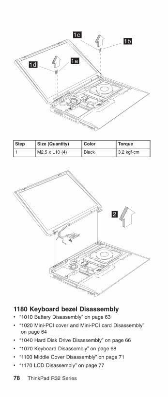
1a
1b1c
1d
Step Size (Quantity) Color Torque
1 M2.5 x L10 (4) Black 3.2 kgf-cm
2
1180 Keyboard bezel Disassemblyv “1010 Battery Disassembly” on page 63
v “1020 Mini-PCI cover and Mini-PCI card Disassembly”on page 64
v “1040 Hard Disk Drive Disassembly” on page 66
v “1070 Keyboard Disassembly” on page 68
v “1100 Middle Cover Disassembly” on page 71
v “1170 LCD Disassembly” on page 77
78 ThinkPad R32 Series

1
Step Size (Quantity) Color Torque
1 M2.5 x L10 (7) Black 3.2 kgf-cm
MT 2658/2659/2677 79

2
CAUTION:The keyboard bezel has several latches. Whenremoving the keyboard bezel from the bottom cover,gently release these latches, then raise the side of thekeyboard bezel facing the palm rest to remove it. Becareful not to break the latches.
1190 VGA Heat Sink Disassemblyv “1010 Battery Disassembly” on page 63
v “1020 Mini-PCI cover and Mini-PCI card Disassembly”on page 64
v “1040 Hard Disk Drive Disassembly” on page 66
v “1070 Keyboard Disassembly” on page 68
v “1090 Safety Cover Disassembly” on page 70
v “1100 Middle Cover Disassembly” on page 71
v “1170 LCD Disassembly” on page 77
v “1160 Coaxial Cable and Inverter Cable Disassembly”on page 76
v “1180 Keyboard bezel Disassembly” on page 78
80 ThinkPad R32 Series

1
Step Size (Quantity) Color Torque
1 M2.5 x L5 (1) Silver 2.5 kgf-cm
1200 PCMCIA Holder Disassemblyv “1010 Battery Disassembly” on page 63
v “1070 Keyboard Disassembly” on page 68
v “1030 Memory cover and Memory card Disassembly” onpage 65
1
MT 2658/2659/2677 81

2c2a
2b
2d
Step Size (Quantity) Color Torque
2 M2 x L6 (4) Silver 1.6 kgf-cm
3
Note: Before removing and replacing the PCMCIA holder,make sure that the PCMCIA cards are removed andthe eject levers are sticking out.
1210 Heat Sink Module Disassemblyv “1010 Battery Disassembly” on page 63
v “1070 Keyboard Disassembly” on page 68
v “1100 Middle Cover Disassembly” on page 71
82 ThinkPad R32 Series

1
1a
1b1c
1d
Step Size (Quantity) Color Torque
1 CPU SpecialScrew(4)
Silver 2.5 kgf-cm
Note: Thermal Pad must be replaced when either HeatSink Module, CPU or System Board is replaced.Thermal Pad is stuck on the bottom side of HeatSink Module with adhesive. Do not re-use thethermal pad.
1220 Fan Disassemblyv “1010 Battery Disassembly” on page 63
v “1070 Keyboard Disassembly” on page 68
v “1100 Middle Cover Disassembly” on page 71
MT 2658/2659/2677 83

1a
1b
1c
2
Step Size (Quantity) Color Torque
1 M2.5 x L5 (3) Silver 2.5 kgf-cm
1230 CPU Disassemblyv “1010 Battery Disassembly” on page 63
v “1070 Keyboard Disassembly” on page 68
v “1100 Middle Cover Disassembly” on page 71
v “1210 Heat Sink Module Disassembly” on page 82
1
84 ThinkPad R32 Series

2
Note: Thermal Pad must be replaced when either HeatSink Module, CPU or System Board is replaced.Thermal Pad is stuck on the bottom side of HeatSink Module with adhesive. Do not re-use thethermal pad.
1240 Speaker Disassemblyv “1010 Battery Disassembly” on page 63
v “1020 Mini-PCI cover and Mini-PCI card Disassembly”on page 64
v “1040 Hard Disk Drive Disassembly” on page 66
v “1070 Keyboard Disassembly” on page 68
v “1100 Middle Cover Disassembly” on page 71
v “1170 LCD Disassembly” on page 77
v “1180 Keyboard bezel Disassembly” on page 78
2
1
MT 2658/2659/2677 85
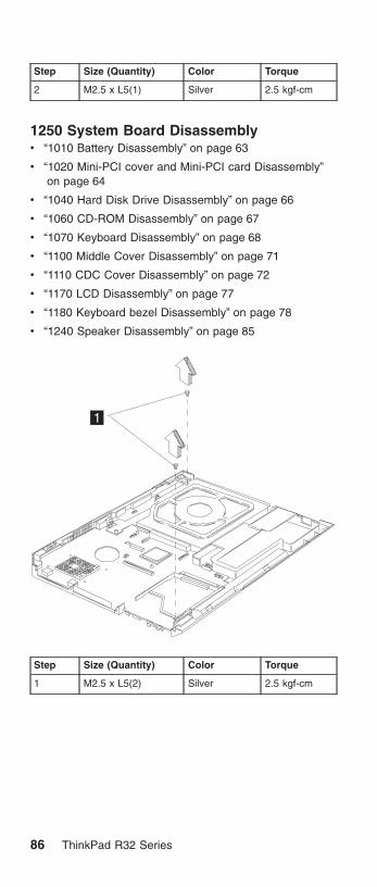
Step Size (Quantity) Color Torque
2 M2.5 x L5(1) Silver 2.5 kgf-cm
1250 System Board Disassemblyv “1010 Battery Disassembly” on page 63
v “1020 Mini-PCI cover and Mini-PCI card Disassembly”on page 64
v “1040 Hard Disk Drive Disassembly” on page 66
v “1060 CD-ROM Disassembly” on page 67
v “1070 Keyboard Disassembly” on page 68
v “1100 Middle Cover Disassembly” on page 71
v “1110 CDC Cover Disassembly” on page 72
v “1170 LCD Disassembly” on page 77
v “1180 Keyboard bezel Disassembly” on page 78
v “1240 Speaker Disassembly” on page 85
1
Step Size (Quantity) Color Torque
1 M2.5 x L5(2) Silver 2.5 kgf-cm
86 ThinkPad R32 Series

23
Notes:
1. When removing the system board from the bottomcover, gently raise the side of the system board facingthe rear I/O ports; then pull out the system board.
2. In step 2, further pull out this latch before the systemboard is attached to the lower case.
3. Thermal Pad must be replaced when either Heat SinkModule, CPU or System Board is replaced. ThermalPad is stuck on the bottom side of Heat Sink Modulewith adhesive. Do not re-use the thermal pad.
1260 I/O Port Bracket Disassemblyv “1010 Battery Disassembly” on page 63
v “1020 Mini-PCI cover and Mini-PCI card Disassembly”on page 64
v “1040 Hard Disk Drive Disassembly” on page 66
v “1060 CD-ROM Disassembly” on page 67
v “1070 Keyboard Disassembly” on page 68
v “1100 Middle Cover Disassembly” on page 71
v “1110 CDC Cover Disassembly” on page 72
v “1170 LCD Disassembly” on page 77
v “1180 Keyboard bezel Disassembly” on page 78
v “1240 Speaker Disassembly” on page 85
v “1250 System Board Disassembly” on page 86
MT 2658/2659/2677 87

1
2
Step Size (Quantity) Color Torque
1 M2.5 x L6 Silver 3.2 kgf-cm
2 M2 x L12 Silver 1.6 kgf-cm
3
45
6
7 8
88 ThinkPad R32 Series

Step Size (Quantity) Color Torque
4 Hex Screw(4) Silver 2.5 kgf-cm
Note: When attaching the I/O port bracket to the systemboard, please pay special attention to the studs’positions as marked 5, 6, 7, 8. The one marked 5should be installed above the one marked 6; theone marked number 7 should be aligned with andattached beneath the one marked number 8.
CAUTION:There are several types of system board FRU for theThinkpad R32 series, as followed:
v System board with IBM security chip
a
v System board without IBM security chip
a
Begin by checking the FRU number of the systemboard, and be sure to use the correct system boardFRU for the computer. For the FRU numbers,see“Parts list” on page 161
MT 2658/2659/2677 89

ImportantIf the ThinkPad computer you are servicing has thesecurity chip, mind the following:
v Do not remove the security chip from thesystem board. If the security chip is removed byaccident, reintall it on the system boardimmediately. Then make sure that it is firmly fixedon the system board and does not remove easily.
v The security chip cannot be used with any othersystem board.
v The system board cannot be used with any othersecurity chip.
v The system board cannot be used withoutsecurity chip
v When you return the defective system boardFRU, you must check whether the security chip isfirmly attached to the system board. If it is notembedded, it may not be covered under warranty.
1270 LCD Bezel Disassembly (14.1″)v “1010 Battery Disassembly” on page 63
v “1020 Mini-PCI cover and Mini-PCI card Disassembly”on page 64
v “1070 Keyboard Disassembly” on page 68
v “1100 Middle Cover Disassembly” on page 71
v “1170 LCD Disassembly” on page 77
1
90 ThinkPad R32 Series

2
Step Size (Quantity) Color Torque
2 M2.5 x L6(2) Black 2.5 kgf-cm
3
3
4
5
6
7
Note: When removing the LCD, take note of the following:
v Be careful not to scratch the LCD bezel whenremoving the screw mylars.
v The LCD bezel has several latches. Releasethese latches; then remove the LCD bezel. Becareful not to break these latches.
v Gently push the two LCD latches outward toremove the LCD bezel.
1280 LCD Inveter Disassembly(14.1″)v “1010 Battery Disassembly” on page 63
v “1020 Mini-PCI cover and Mini-PCI card Disassembly”on page 64
MT 2658/2659/2677 91

v “1070 Keyboard Disassembly” on page 68
v “1100 Middle Cover Disassembly” on page 71
v “1170 LCD Disassembly” on page 77
v “1270 LCD Bezel Disassembly (14.1″)” on page 90
23
1a1b
Step Size (Quantity) Color Torque
1 M2 x L10(2) Black 2.5 kgf-cm
1290 LCD Board Disassembly(14.1″)v “1010 Battery Disassembly” on page 63
v “1020 Mini-PCI cover and Mini-PCI card Disassembly”on page 64
v “1070 Keyboard Disassembly” on page 68
v “1100 Middle Cover Disassembly” on page 71
v “1170 LCD Disassembly” on page 77
v “1270 LCD Bezel Disassembly (14.1″)” on page 90
v “1280 LCD Inveter Disassembly(14.1″)” on page 91
1
92 ThinkPad R32 Series

2
Step Size (Quantity) Color Torque
2 M2 x L4(2) Silver 2.5 kgf-cm
3a
3b
4
Step Size (Quantity) Color Torque
3 M2.5 x L6(2) Black 2.5 kgf-cm
MT 2658/2659/2677 93

Note: Before step 4 of removing the LED board, pleasemake sure the main antenna cable is lifted gently.
5
6
1300 LCD Bracket Hinges Disassembly(14.1″)v “1010 Battery Disassembly” on page 63
v “1020 Mini-PCI cover and Mini-PCI card Disassembly”on page 64
v “1070 Keyboard Disassembly” on page 68
v “1100 Middle Cover Disassembly” on page 71
94 ThinkPad R32 Series

v “1170 LCD Disassembly” on page 77
v “1270 LCD Bezel Disassembly (14.1″)” on page 90
v “1280 LCD Inveter Disassembly(14.1″)” on page 91
v “1290 LCD Board Disassembly(14.1″)” on page 92
1a1b
1c
1d
Step Size (Quantity) Color Torque
1 M2 x L4 (4) Silver 2.5 kgf-cm
1310 Main Antenna Disassembly(14.1″)v “1010 Battery Disassembly” on page 63
v “1020 Mini-PCI cover and Mini-PCI card Disassembly”on page 64
v “1070 Keyboard Disassembly” on page 68
v “1100 Middle Cover Disassembly” on page 71
v “1170 LCD Disassembly” on page 77
v “1270 LCD Bezel Disassembly (14.1″)” on page 90
v “1280 LCD Inveter Disassembly(14.1″)” on page 91
v “1290 LCD Board Disassembly(14.1″)” on page 92
v “1300 LCD Bracket Hinges Disassembly (14.1″)” onpage 94
MT 2658/2659/2677 95

1
Step Size (Quantity) Color Torque
1 M2 x L4(1) Silver 2.5 kgf-cm
1320 Main Antenna Cable Reassemblyv “1010 Battery Disassembly” on page 63
v “1020 Mini-PCI cover and Mini-PCI card Disassembly”on page 64
v “1070 Keyboard Disassembly” on page 68
v “1100 Middle Cover Disassembly” on page 71
v “1170 LCD Disassembly” on page 77
v “1270 LCD Bezel Disassembly (14.1″)” on page 90
v “1280 LCD Inveter Disassembly(14.1″)” on page 91
v “1290 LCD Board Disassembly(14.1″)” on page 92
v “1300 LCD Bracket Hinges Disassembly (14.1″)” onpage 94
96 ThinkPad R32 Series

MT 2658/2659/2677 97

Locations
Front View
TrackPoint
System-status indicators
Computer display
Ultrabay Plus
Rear View
Power jack
Ethernet connectorMonitor connector
USB connector
TV port
Modem connectorParallel port
98 ThinkPad R32 Series

Bottom View
1
2
3
4
1. Battery pack
2. Memory slot door
3. Mini-PCI Card slot door
4. Docking connector
MT 2658/2659/2677 99

Switch Locations
SW2
Pin11 0
BootBlockDisabled
BootBlockEnabled
Pin2
CheckPasswordEnabled
1 0 1 0
CheckPasswordDisabled
01
100 ThinkPad R32 Series

Parts list
15
1
2
4
56
7
11
12
1314 16
17
18
19
21
9
20
10
8
23
22
3
8
Note: The parts marked with asterisk are CRUs (customerreplaceable units.)
MT 2658/2659/2677 101

There are two levels of CRUs: Tier 1 and Tier 2. Tier 1CRUs are identified by one asterisk (*). Tier 2 CRUs areidentified by 2 asterisks ( * *).
Tier 1 CRUs are defined as those CRUs that meet thefollowing criteria:
1. No tools required for removal or replacement.
Exception: Coin, thumb screws are acceptable.
2. Minimal technical expertise required.
3. Minimal Problem Determination is required (less than 5minutes).
Tier 2 CRUs are defined as those CRUs that meet thefollowing criteria:
1. Some screw/fastener removals.
2. Some technical experience required.
3. Helpcenter assistance may be used.
4. Problem Determination can be done by customers orwith Helpcenter assistance.
No. Description FRU No.
1 Hinge Cap 26P9722
LG/ IBM Logo Kit 08K5860
3 Middle Cover Asm 46L6509
4 Upper Case-KBD Bezel 46L6508
5 Antenna Kit 13″/14″ LCD
Antenna R (Aux) 13″/14″
27L0723
46L6324
6 Cable Asm. kit , RJ11 and lid switch 27L0722
7 Planar for Pentium-4M w/o securitycard, w/o 1394
26P8292
Planar for Pentium-4M w/ security card,w/ 1394
26P8341
Planar for Pentium-4M w/o securitycard, w/1394
26P8291
Planar for Pentium-4M w/ security card,w/o 1394
26P8343
8 M/B Misc parts kit 46P2586
9 PC Card Slot 46L6530
10 HDD w/tray & screws module IBMCsacard./ 20 GB
08K9761* *
HDD w/tray & screws module HITACHIDogwood/ 20GB
08K9763**
HDD w/tray & screws module IBMCsacard / 30 GB
08K9733**
HDD w/tray & screws module HITACHIDogwood/ 30GB
08K9746**
102 ThinkPad R32 Series

No. Description FRU No.
HDD w/tray & screws module IBMCsacard / 40 GB
08K9742**
HDD w/tray & screws module HITACHIDogwood/ 40GB
08K9774**
11 HDD Cover 46L6523
12 Lower Case w/ label W/W 46L6513
Lower Case w/ label EMEA 46L6514
Lower Case w/ label IIPC 46L6515
Lower Case w/ label Korea 46L6516
Lower Case w/ label Taiwan 46L6517
Lower Case w/ label W/W-wireless 46L6518
Lower Case w/ label EMEA-wireless 46L6519
Lower Case w/ label IIPC-wireless 46L6520
Lower Case w/ label Korea-wireless 46L6521
Lower Case w/ label Taiwan 46L6522
13 CARD ASM DDR- 128M 10K0029**
CARD ASM DDR- 256M 10K0031**
CARD ASM DDR- 512M 10K0033**
14 Combo 802.11b/Modem 12P3863
Actiontec Mini-PCI Wireless Card 26P8513
IBM High Rate Wireless Mini-PCIAdapter
26P8472
15 Mini-PCI / DIMM door kit 46L6524
16 Main Battery Assy. (Li-Ion)
Sanyo-W/W
Sanyo-Japan
Panasonic-W/W
Panasonic-Japan
02K7054*
02K7058*
02K6928*
02K7060*
17 Speaker Kit 08K4618
18 RTC Battery(P/N 02K7063) 02K7062
19 CD-ROM Module
TEAC (CD-224E-B01)
LG (CRN-8245B)
27L3436*
27L4301*
DVD-ROM Module
Hitachi (GDR-8081N)
MKE (SR-8176–MBZ)
27L4355*
27L4351*
MT 2658/2659/2677 103

No. Description FRU No.
CD—RW Module
TEAC (CD-W28E-001)CD—RW /12XDVD Module
KME UJDA720
27L4297*
27L4359*
FDD External, Unit P/N 05K9282 05K9283*
Rubber Kit 46L6527
Mylar Kit 46P2589
Screw Kit 46L6526
Base cover Misc parts kit 46P2587
20 FAN asm 46L6507
21 Heat Sink Asm. (w/ thermal pad) 46P2588
22 I/O Bracket 46P2590
23 CPU Intel Pentium-4M 1.7 GHz 26P8449
CPU Intel Pentium-4M 1.6 GHz 26P8345
CPU Intel Pentium-4M 1.8 GHz 26P8346
104 ThinkPad R32 Series

LCD FRU
13.3-inch TFT:
1
2
3
34
56
7
No. Description FRU No.
1 LCD Bezel asm ″R32″ (13″ TFT) 46L6505
2 LCD Panel asm (13″ TFT)
Tori-Sanyo
LG
11P8212
11P8220
3 LCD Hinge/Bracket kit (13″ TFT) 26P9720
4 LCD Invertor / LED card 14/13″ TFT(P/N 26P8140)
26P8139
5 LCD cable Asm. (13″TFT) 27L0721
6 Antenna Kit 13″/14″ LCD
Antenna L (Main) 13″/14″
27L0723
46L6323
7 LCD Rear Cover asm (13/14″TFT)-Wireless
26P9709
MT 2658/2659/2677 105

No. Description FRU No.
LCD Rear Cover asm (13/14″ TFT) 26P9707
14.1-inch TFT:
1
2
3
34
5
6
7
No. Description FRU No.
1 LCD Bezel asm ″R32″ (14″ TFT) 46L6503
2 LCD Panel asm (14″ TFT)
DBU
LG/LW
Samsung
05K9888
11P8283
11P8280
3 LCD Hinge/Bracket kit (14″ TFT) 26P9719
4 LCD Invertor / LED card 14/13″ TFT(P/N 26P8140)
26P8139
5 LCD cable asm (14″ TFT) 27L0720
106 ThinkPad R32 Series

No. Description FRU No.
6 Antenna Kit 13″/14″ LCD
Antenna L (Main) 13″/14″
27L0723
46L6323
7 LCD Rear Cover asm (13/14″TFT)-Wireless
26P9709
LCD Rear Cover asm (13/14″ TFT) 26P9707
Keyboard
Description Vendor FRU No.
KBD ASM US English NMB 08K4506**
KBD ASM Canadian French NMB 08K4508**
KBD ASM German NMB 08K4510**
KBD ASM UK English NMB 08K4512**
KBD ASM French NMB 08K4514**
KBD ASM Dutch NMB 08K4516**
KBD ASM Swedish/Finnish NMB 08K4518**
KBD ASM Norwegian NMB 08K4520**
KBD ASM Danish NMB 08K4522**
KBD ASM Italian NMB 08K4524**
KBD ASM European Spanish NMB 08K4526**
KBD ASM Belgian NMB 08K4528**
KBD ASM Switzerland NMB 08K4530**
KBD ASM Portuguese NMB 08K4532**
KBD ASM Arabic NMB 08K4534**
KBD ASM Russian NMB 08K4536**
KBD ASM Hebrew NMB 08K4538**
KBD ASM Polish NMB 08K4540**
KBD ASM Turkish NMB 08K4542**
KBD ASM Czech NMB 08K4544**
KBD ASM Hungarian NMB 08K4546**
KBD ASM Greek NMB 08K4548**
KBD ASM Slovenian NMB 08K4550**
KBD ASM Slovakian NMB 08K4552**
KBD ASM Japanese NMB 08K4554**
KBD ASM Traditional Chinese NMB 08K4556**
KBD ASM Korean NMB 08K4558**
KBD ASM La Spanish NMB 08K4560**
KBD ASM US English Chicony 08K4562**
KBD ASM Canadian French Chicony 08K4564**
KBD ASM German Chicony 08K4566**
MT 2658/2659/2677 107
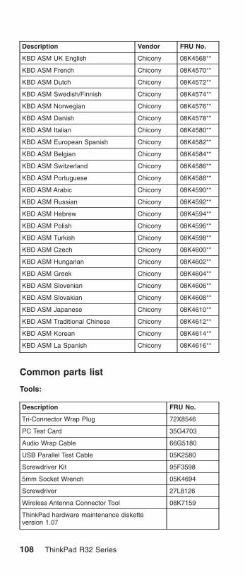
Description Vendor FRU No.
KBD ASM UK English Chicony 08K4568**
KBD ASM French Chicony 08K4570**
KBD ASM Dutch Chicony 08K4572**
KBD ASM Swedish/Finnish Chicony 08K4574**
KBD ASM Norwegian Chicony 08K4576**
KBD ASM Danish Chicony 08K4578**
KBD ASM Italian Chicony 08K4580**
KBD ASM European Spanish Chicony 08K4582**
KBD ASM Belgian Chicony 08K4584**
KBD ASM Switzerland Chicony 08K4586**
KBD ASM Portuguese Chicony 08K4588**
KBD ASM Arabic Chicony 08K4590**
KBD ASM Russian Chicony 08K4592**
KBD ASM Hebrew Chicony 08K4594**
KBD ASM Polish Chicony 08K4596**
KBD ASM Turkish Chicony 08K4598**
KBD ASM Czech Chicony 08K4600**
KBD ASM Hungarian Chicony 08K4602**
KBD ASM Greek Chicony 08K4604**
KBD ASM Slovenian Chicony 08K4606**
KBD ASM Slovakian Chicony 08K4608**
KBD ASM Japanese Chicony 08K4610**
KBD ASM Traditional Chinese Chicony 08K4612**
KBD ASM Korean Chicony 08K4614**
KBD ASM La Spanish Chicony 08K4616**
Common parts list
Tools:
Description FRU No.
Tri-Connector Wrap Plug 72X8546
PC Test Card 35G4703
Audio Wrap Cable 66G5180
USB Parallel Test Cable 05K2580
Screwdriver Kit 95F3598
5mm Socket Wrench 05K4694
Screwdriver 27L8126
Wireless Antenna Connector Tool 08K7159
ThinkPad hardware maintenance disketteversion 1.07
108 ThinkPad R32 Series

Note: The data may look the same with the sample hmmbut the diskette version is different. There is no FRUnumber for ThinkPad hardware maintenancediskette.
Telephone cable:
Description FRU No.
Telephone cable (US/ CAN/ TWN/ APS/ LA/BRZL)
27L0465*
Telephone cable (UK/ IR/ NZ) 27L0442*
Telephone cable (GERMANY) 27L0441*
Telephone cable (ITALY) 27L0448*
Telephone cable (FRANCE) 27L0443*
Telephone cable (DK/ DE/ PO) 27L0447*
Telephone cable (SW/ SU) 27L0445*
Telephone cable (FI/ NO/ NS) 27L0446*
Telephone cable (AUSTRALIA) 27L0467*
Telephone cable (ND/ NU) 27L0444*
Telephone cable (SF/ SI/ SG/ SE) 27L0462*
Telephone cable (BE/ BK/ BS/ BD/ BF) 27L0451*
Telephone cable (AUSTRIA) 27L0449*
Telephone cable (SPAIN) 27L0450*
AC adapter:
Description FRU No.
AC Adapter, 72W 3-pins (ASTEC) 02K6751*
AC Adapter, 72W 3-pins (Delta) 02K6754*
AC Adapter, 72W 2-pins (Delta) 02K6756*
AC Adapter, 72W 2-pins (ASTEC) 02K6753*
Power cords: IBM power cords for a specific country areusually available only in that country.
For 2–pin power cords:
IBM powercord partnumber Used in these countries or regions
13H5264* Canada, U.S.A.
13H5273* Japan
36L8870* Argentina
49P2095* Brazil
For 3–pin power cords:
MT 2658/2659/2677 109

Note: The grounded adapter is required for full MPRIIcompliance. If a 3–pin power cord came with yourcomputer, see “Safety Information” on page 11.
IBM powercord partnumber Used in these countries or regions
76H3514* Australia, New Zealand
76H3516* Taiwan, Thailand
76H3530* Italy
76H3520* Denmark
76H3524* UK, Hong Kong
76H3518* European Countries
76H3522* South Africa, India
76H3532* Israel
76H3535* Korea
02K0539* China (P.R.C.)
76H3528* Switzerland
Recovery CD List:
Description FRU No. MODELS
Recovery CDWin-XP Pro(US/CA/AP)
32P7780 2677–CFU, CGU:2659–BPU, BQU,CFU, CGU, CHU
Recovery CDWin-XP Pro(US/CA/AP)
32P7780 2658–BPU, BQU,CFU, CGU, CHU,A5U, A6U, A7U,A8U, A9U, AAU,BKU, CRU, CSU,CTU
Recovery CDWin-XP Pro(US/CA/AP)
32P7780 2677–CFH, CGH:2659–BPH, BQH,CFH, CGH, CHH:2658–BPH, BQH,CFH, CGH, CHH,BDH, BJH, CVH
Recovery CDWin-XP Pro(US/CA/AP)
32P7780 2677–CFM, CGM:2659–BPM, BQM,CFM, CGM, CHM
Recovery CDWin-XP Pro(US/CA/AP)
32P7780 2658–BPM, BQM,CFM, CGM, CHM,A5M, A9M, BCM,BUM, BLM, BVM,CPM, CTM
Recovery CDJapan-XP Pro
62P8864 2677–CFJ, CGJ:2659–BPJ, BQJ,CFJ, CGJ, CHJ:2658–BPJ, BQJ,CFJ, CGJ, CHJ,BGJ, BRJ, BTJ
110 ThinkPad R32 Series

Recovery CDWin-XP Pro (LA-BR)
32P7784 2677–CFG, CGG:2659–BPG, BQG,CFG, CGF, CHG:2658–BPG, BQG,CFG, CGG, CHG,BAG, BJG, CMG,CNG, CUG
Recovery CDWin-XP Pro (LA-BR)
32P7784 2677–CFP, CGP:2659–BPP, BQP,CFP, CGP:2658–BPPS, BQP,CFP, CGP, A5P,CRP, CTP
Recovery CDWin-XP Pro (DK)
32P7785 2677–CFG, CGG:2659–BPG, BQG,CFG, CGF, CHG:2658–BPG, BQG,CFG, CGG, CHG,BAG, BJG, CMG,CNG, CUG
Recovery CDWin-XP Pro (FR)
32P7786 2677–CFG, CGG:2659–BPG, BQG,CFG, CGF, CHG:2658–BPG, BQG,CFG, CGG, CHG,BAG, BJG, CMG,CNG, CUG
Recovery CDWin-XP Pro (FR)
32P7786 2677–CFF, CGF:2659–BPF, BQF,CFF, CGF, CHF:2658–BPS, BQS,CFS, CGF, CHF,SSF, CLF, CTF
Recovery CDWin-XP Pro (GR)
32P7787 2677–CFG, CGG:2659–BPG, BQG,CFG, CGF, CHG:2658–BPG, BQG,CFG, CGG, CHG,BAG, BJG, CMG,CNG, CUG
Recovery CDWin-XP Pro (SP)
32P7788 2677–CFG, CGG:2659–BPG, BQG,CFG, CGF, CHG:2658–BPG, BQG,CFG, CGG, CHG,BAG, BJG, CMG,CNG, CUG
Recovery CDWin-XP Pro (SP)
32P7788 2677–CFS, CGS:2659–BPS, BQS,CFS, CGS:2658–BPS, BQS,CFS, CGS, A5S,CRS, CTS
Recovery CDWin-XP Pro (SP)
32P7788 2677–CFX, CGX:2659–BPX, BQX,CFX, CGX:2658–BPX, BQX,CFX, CGX, A5X,CRX, CTX
MT 2658/2659/2677 111

Recovery CDWin-XP Pro (SV)
32P7789 2677–CFG, CGG:2659–BPG, BQG,CFG, CGF, CHG:2658–BPG, BQG,CFG, CGG, CHG,BAG, BJG, CMG,CNG, CUG
Recovery CDWin-XP Pro (IT)
32P7790 2677–CFG, CGG:2659–BPG, BQG,CFG, CGF, CHG:2658–BPG, BQG,CFG, CGG, CHG,BAG, BJG, CMG,CNG, CUG
Recovery CDWin-XP Pro (FI)
32P7791 2677–CFG, CGG:2659–BPG, BQG,CFG, CGF, CHG:2658–BPG, BQG,CFG, CGG, CHG,BAG, BJG, CMG,CNG, CUG
Recovery CDWin-XP Pro (NI)
32P7792 2677–CFG, CGG:2659–BPG, BQG,CFG, CGF, CHG:2658–BPG, BQG,CFG, CGG, CHG,BAG, BJG, CMG,CNG, CUG
Recovery CDWin-XP Pro (NO)
32P7793 2677–CFG, CGG:2659–BPG, BQG,CFG, CGF, CHG:2658–BPG, BQG,CFG, CGG, CHG,BAG, BJG, CMG,CNG, CUG
Recovery CDWin2000 (US/ CA/AP)
32P7575 2659–BMU, BNU:2658–BMU, BNU,A2U, C4UC5U
Recovery CDWin2000 (US/ CA/AP)
32P7575 2659–BMH, BNH:2658–BMH, BNH
Recovery CDWin2000 (US/ CA/AP)
32P7575 2659–BMM, BNM:2658–BMM, BNM
Recovery CDWin2000 (US/ CA/AP)
32P7575 2659–BMA, BNA:2658–BMA, BNA,C2A, C3A
Recovery CDWin2000 (LA-BR)
32P7579 2659–BMG, BNG:2658–BMG, BNG,C2G, C3G
Recovery CDWin2000 (LA-BR)
32P7579 2659–BMP, BNP:2658–BMP, BNP
Recovery CDWin2000 (DK)
32P7580 2659–BMG, BNG:2658–BMG, BNG,C2G, C3G
Recovery CDWin2000 (FR)
32P7581 2659–BMG, BNG:2658–BMG, BNG,C2G, C3G
112 ThinkPad R32 Series

Recovery CDWin2000 (FR)
32P7581 2659–BMF, BNF:2658–BMF, BNF,A2F, C4F, C5F
Recovery CDWin2000 (GR)
32P7582 2659–BMG, BNG:2658–BMG, BNG,C2G, C3G
Recovery CDWin2000 (SP)
32P7583 2659–BMG, BNG:2658–BMG, BNG,C2G, C3G
Recovery CDWin2000 (SP)
32P7583 2659–BMX, BNX:2658–BMX, BNX
Recovery CDWin2000 (SP)
32P7583 2659–BMS, BNS:2658–BMS, BNS
Recovery CDWin2000 (SV)
32P7584 2659–BMG, BNG:2658–BMG, BNG,C2G, C3G
Recovery CDWin2000 (IT)
32P7585 2659–BMG, BNG:2658–BMG, BNG,C2G, C3G
Recovery CDWin2000 (FI)
32P7586 2659–BMG, BNG:2658–BMG, BNG,C2G, C3G
Recovery CDWin2000 (NL)
32P7587 2659–BMG, BNG:2658–BMG, BNG,C2G, C3G
Recovery CDWin2000 (NO)
32P7588 2659–BMG, BNG:2658–BMG, BNG,C2G, C3G
Recovery CDJapan-Win2000 (JP)
62P8861 2659–BMJ, BNJ:2658–BMJ, BNJ,A3J, BHJ, BSJ
Recovery CD WinXP Home (US/ CA/AP)
32P7678 2658–A4U, C6U,CCU, CDU
Recovery CD WinXP Home (US/ CA/AP)
32P7678 2658–A4A, ABA,B5A, B6A
Recovery CD WinXP Home (US/ CA/AP)
32P7678 2658–C6M
Recovery CD WinXP Home (LA-BR)
32P7682 2658–B2G, B3G
Recovery CD WinXP Home (LA-BR)
32P7682 2658–A4P, C6P,CCP, CDP
Recovery CD WinXP Home (DK)
32P7683 2658–B2G, B3G
Recovery CD WinXP Home (FR)
32P7684 2658–B2G, B3G
Recovery CD WinXP Home (GR)
32P7685 2658–B2G, B3G
Recovery CD WinXP Home(SP)
32P7686 2658–B2G, B3G
MT 2658/2659/2677 113

Recovery CD WinXP Home(SP)
32P7686 2658–A4S, C6S,CCS, CDS
Recovery CD WinXP Home(SP)
32P7686 2658–A4X, C6X,CCX, CDX
Recovery CD WinXP Home (SV)
32P7687 2658–B2G, B3G
Recovery CD WinXP Home (IT)
32P7688 2658–B2G, B3G
Recovery CD WinXP Home (FI)
32P7689 2658–B2G, B3G
Recovery CD WinXP Home (NL)
32P7690 2658–B2G, B3G
Recovery CD WinXP Home (NO)
32P7691 2658–B2G, B3G
Option Parts List
Battery charges:
Description FRU No.
Main Battery Li-Ion Option—W/W 02K7052*
Main Battery Li-Ion Sanyo—W/W 02K7055*
Main Battery Li-Ion Panasonic—W/W 02K7057*
Main Battery Li-Ion Option—Japan 02K7053*
Main Battery Li-Ion Sanyo—Japan 02K7059*
Main Battery Li-Ion Panasonic—Japan 02K7061*
Ultrabay devices:
Description FRU No.
CD-RW/ DVD Combo II (KME) 27L4359*
CD-RW/ DVD Combo II (TEAC) 08K9785*
8X/ 4X/ 24X Max CD-RW (TEAC) 08K9644*
Ultralight 8X DVD-ROM (MKE) 27L4351*
Ultralight 8X DVD-ROM (HLDS) 27L4355*
24X-10X CD-ROM (HLDS) 27L4301*
24X-10X CD-ROM (TEAC) 27L3436*
Diskette drive (TEAC) 08K9606*
Diskette drive (SONY) 08K9607*
SuperDisk drive (LS240) 08K9615*
ZIP—250 drive 00N8254*
2nd HDD adapter 08K6067*
Ultrabay Plus device carrier 26P9388*
Ultrabay Plus numeric keypad 19K2056*
Ultrabay Plus cradle for WorkPad c500 series 26P9389*
114 ThinkPad R32 Series

ThinkPad R32 Series Part II
This section applies to the following models: 2677–BZX,2659–CHX, 2659–BZX, 2658–CHX, 2658–BZX,2658–DFX, 2658–G2X, 2658–G3X.
MT 2658/2659/2677 115

Product overviewThe following shows an overview of the system features.
Feature Description
Processor Intel Pentium-4M–1.6GHz/1.7GHz/1.8GHz Intel
Chip set Intel Brookdale (845MP)
Bus architecture Host bus 64 bits 266 MHz, PCI 32bits/33 MHz, ISA 16 bits/8.33MHz,PCMCIA 16 bits/33 MHz, Cardbus 32bits/32 MHz
System memory Two DDR DIMM Slots support 128MB,256MB, and 512MB DIMM card, up toMax. 1GB
Maximum frequency: PC 266 MHz
Maximum size: 1024 MB
CMOS RAM 256 bytes
Video ATI M6C graphics integrated V-RAMchip (8MB/16MB)
14.1– inch, 32 bit true colors,1024X768 pixel TFT XGA color LCD
Video memory 8/16MB V-RAM in video chip
LCD(Bright Ctrl) 13.3″ TFT (XGA)/ 14.1″ TFT (XGA)(KBD)
Audio AC97 audio based on the Intel ICH3AC link DMA engine
16– bit audio
Internal stereo speakers
Floppy Diskette drive(By model)
USB FDD External 1.44MB, 3.5 inchfloppy drive via USB interface(Bootable)
Hard disk drive-Upgradable
20GB, 30GB or 40GB, 2.5–inch9.5mm height, E-IDE interface
Ultrabay Plus 24X CD/ 8X DVD/ 8X, 4X, 24X MaxCD-RW/ CD-RW- DVD (Combo)/ BayBattery support, NEATS
Modem V.90 Soft modem (MDC) IntegratedCDC soft modem on the Intel ICH3 AClink DMA engine 56 Kbps Data /FaxModem.
Ethernet Intel Ethernet LOM
IEEE 1394 (on planar) On planar (Pop/ Depop) TiTSB43AB21 1394 controller on board
IEEE 1394.a 4-pin connector –nocable power 100 Mbps, 200 Mbps and400 Mbps.
CDC One CDC slot (MDC)
116 ThinkPad R32 Series

Feature Description
Mini-PCI One Mini-PCI slot (802. 11b)
Antenna (By Model) Yes
PC Card (PCMCIA) T2x1 or T3x1 (Cardbus w/o ZV Port)Two Type I/II or oneType III
ThinkLight Yes
IR Yes
I/O ports External monitor
Parallel
CRT
Two USB
Headphone
Mic-in
Speaker-out
Telephone (RJ11)
LAN (RJ45)
TV-out (S-Video)
Docking (for port Replicator)
DC-in
IEEE 1394 port (IEEE 1394 modeonly)
Security chip support TCPA Security
Power 72–Watt AC Adapter
8–cell Li-Ion Intelligent Battery Pack
BIOS IBM BIOS
Status indicatorsThe system-status indicators on the computer show thecurrent status of your computer by their on or off statesand colors (green and orange). Each indicator is identifiedwith a symbol. The following shows the location and the
MT 2658/2659/2677 117

meaning of each icon:
Symbol Color Meaning
(1) Drive in use Green Data is being read from orwritten to the hard disk. Donot enter standby mode orpower off the computerwhen this indicator is on.
(2) Numeric lock Green The numeric keypad on thekeyboard is enabled. Youenable or disable thekeypad by pressing andholding the Shift key, andpressing the NumLk key.For details, see the User’sReference.
(3) Caps lock Green Caps Lock mode isenabled. All alphabeticcharacters (A-Z) areentered in capital letterswithout the Shift key beingpressed. You enable ordisable the Caps Lockmode by pressing the CapsLock key.
(4) Scroll lock Green Scroll Lock mode isenabled. The Arrow keyscan be used asscreen-scroll function keys.The cursor cannot bemoved with the Arrowkeys. Not all applicationprograms support thisfunction. You enable ordisable Scroll Lock mode bypressing the ScrLk key.
118 ThinkPad R32 Series

Symbol Color Meaning
(5) Power on Green The computer isoperational. This indicator ison when the computer ison.
(6) Battery status Green Enough battery powerremains for operation.
Blinkinggreen
The battery power chargesup to 80% full power
Blinkingorange
The battery pack needs tobe charged
Orange The battery pack is beingcharged.
(7) Standby mode Green The computer is in standbymode
Symbol Color Meaning
(1) Battery status Green Enough battery powerremains for operation.
Blinkinggreen
The battery power chargesup to 80% full power
Blinkingorange
The battery pack needs tobe charged
Orange The battery pack is beingcharged.
(2) Standby mode Green The computer is in standbymode
MT 2658/2659/2677 119

FRU testsThe following table shows the applicable test for each FRUusing PC-Doctor.
FRU Applicable test
System board 1. CPU/Coprocessor (Diagnostics)
2. System board (Diagnostics)
Power Battery (Diagnostics)
LCD unit 1. Video Adapter (Diagnostics)
2. Video (Interactive Tests)
Modem 1. Make sure the modem set upcorrectly.
2. Replacing the modem jack andmodem card one at a time, run themodem tests in Other Devices(Diagnostics)
Audio Internal Speaker (Interactive Tests)
Stereo Speaker (Interactive Tests)
Speaker System beeper: Internal Speaker(Interactive Tests)
PC Card slots System board (Diagnostics)
Keyboard 1. Keyboard (Diagnostics)
2. Keyboard (Interactive Tests)
TrackPont or Pointingdevice
If the TrackPoint does not work, see if anexternal PS/2 mouse is connected to themouse/keyboard connector and removeit. The TrackPoint is automaticallydisabled if an external PS/2 mouse isattached. Check also if the TrackPointdriver is correctly installed by accessingWindows Device Manager via the Systemicon in the Control Panel.
After you use the TrackPoint, the pointerdrifts on the screen for a short time. Thisself-acting pointer movement can occurwhen a slight, steady pressure is appliedto the TrackPoint pointer. This symptomis not a hardware problem. No serviceactions are necessary if the pointermovement stops in a short period of time.
If this does not correct the TrackPointproblem, continue with the following:Mouse (Interactive Tests).
Hard disk drive Fixed Disks (Diagnostics)
CD-ROM drive CD-ROM, DVD, CD-RW, DVD/CD-RW(Interactive Tests)
120 ThinkPad R32 Series

FRU Applicable test
Memory 1. If a DIMM is installed, remove it andrun Memory Test-Quick (Diagnostics)
2. If the problem does not recur, replacethe DIMM and run the test again.
3. If the test does not detect the error,run Memory Test-Full (Diagnostics)
Fan 1. Power on system and check the airturbulence at the louver at the rear ofthe computer.
2. Run the fan test in Other Devices(Diagnostics).
MT 2658/2659/2677 121

FRU removals and replacementsThis section contains information about removals andreplacements.
v Do not damage any parts. Only certified and trainedpersonnel should service the computer.
v The arrows in this section show the direction ofmovement to remove a FRU, or to turn a screw torelease the FRU. The arrows are marked in numericorder, in square callout, to show the correct sequence ofremoval.
v Any FRUs that must be removed before removing thefailing FRU are listed at the top of the page.
v To replace a FRU, reverse the removal procedure andfollow any notes that pertain to replacement. See“Locations” on page 98 for internal cable connectionsand arrangement information.
v When replacing a FRU, use the correct screw size, asshown in the procedure.
Safety Notice 1Translations in ″Safety Notices (Multi-lingualTranslations)″ section: Before the computer ispowered-on after FRU replacement, make sure allscrews, springs, or other small parts are in placeand are not left loose inside the computer. Verifythis by shaking the computer and listening forrattling sounds. Metallic parts or metal flakes cancause electrical shorts.
Safety Notice 3Translations in ″Safety Notices (Multi-lingualTranslations)″ section: The battery pack containssmall amounts of nickel. Do not disassemble it,throw it into fire or water, or short-circuit it. Disposeof the battery pack as required by local ordinancesor regulations. Use only the battery in theappropriate parts listing when replacing the batterypack. Use of an incorrect battery can result inignition or explosion of the battery.
122 ThinkPad R32 Series

Safety Notice 8Translations in ″Safety Notices (Multi-lingualTranslations)″ section: Before removing any FRU,power-off the computer, unplug all power cords fromelectrical outlets, remove the battery pack, thendisconnect any interconnecting cables.
Attention: The system board is sensitive and can bedamaged by electronic discharge. Establish personalgrounding by touching a ground point with one hand beforetouching these units.
An electrostatic discharge (ESD) strap (P/N: 6405959)must be used to establish personal grounding.
Note: When disassembling the computer, pleasefollow the numerical and alphabetical orderssuch as 1a, 1b, 1c, 1d, 2, 3, 4. Please note thatwhen you assemble the computer, the sequencemarked in number and alphabets should berevervsed, for instance, 4, 3, 2, 1d, 1c, 1b, 1a.
1010 Battery Disassembly
21 2
WarningBattery packs are capable of delivering highcurrents for a significant amount of time. Do notshort the battery terminals.
CAUTION:Danger of explosion if battery is incorrectly replaced.Replace only with the same or equivalent typerecommended by the manufacturer. Dispose of usedbatteries according to the manufacturer’s instructions.
MT 2658/2659/2677 123

1020 Mini-PCI cover and Mini-PCI cardDisassemblyv “1010 Battery Disassembly” on page 123
1
2
Note: The screw does not separate from the PCI cover.
334
Note: There are 2 cables on step 4 : The gray cable is themain antenna and the black cable is the auxiliareyantenna. There is no step 3 if the Mini-PCI card isnot stalled, then this cable will be connected to the
124 ThinkPad R32 Series

CDC card.
Note: When you install the PCI card, remember to insert itinto its socket at 20°, press it down and ensure theconnection is well.
1030 Memory cover and Memory cardDisassemblyv “1010 Battery Disassembly” on page 123
1
2
MT 2658/2659/2677 125

Note: The screws do not separate from the memorycover.
1
2
To install the memory card:
With the notched end of the memory card toward the rightside of the socket, insert the memory card, at an angle ofapproximately 20°, into the socket; then press it firmly.Pivot the memory card until it snaps into place.
Side View
1040 Hard Disk Drive Disassemblyv “1010 Battery Disassembly” on page 123
126 ThinkPad R32 Series

1
2
Step Size (Quantity) Color Torque
1 M3 x L3.5 (1) Black 3.2 kgf-cm
WarningDo not drop or apply any shock to the hard diskdrive. The hard disk drive is sensitive to physicalshock. Incorrect handling can cause damage andpermanent loss of data on the drive.
Before removing the drive, have the user make abackup copy of all the information on the drive ifpossible.
Never remove the drive while the system isoperating or is in suspend mode.
1050 Hard Disk Drive Cover Disassemblyv “1010 Battery Disassembly” on page 123
1
1060 CD-ROM Disassemblyv “1010 Battery Disassembly” on page 123
MT 2658/2659/2677 127

1
2
3
1070 Keyboard Disassemblyv “1010 Battery Disassembly” on page 123
1a 1b
Step Size (Quantity) Color Torque
1 M2.5 x L10 (2) Black 3.2 kgf-cm
128 ThinkPad R32 Series

2
3
4
Notes:
1. When replacing the keyboard, make sure that the cableis clean and insert it directly into the connector, makingsure it makes contact with the bottom of the connector.
2. If the cable do not touch the bottom of the connector,the keyboard function will be rendered useless.
3. The cable of the keyboard are fragile and could bedamaged. Be careful when pulling out the cable.
1080 Backup Battery Disassemblyv “1010 Battery Disassembly” on page 123
v “1070 Keyboard Disassembly” on page 128
MT 2658/2659/2677 129

1
2
CAUTION:Danger of explosion if battery is incorrectly replaced.Replace only with the same or equivalent typerecommended by the manufacturer. Dispose of usedbatteries according to manufacturer’s instruction.
Safety Notice 4Translation in ″Safety Notices: Multi-lingualTranslations″ section: The backup battery is alithium battery and can cause a fire, an explosion, orsevere burns. Do not recharge it, remove itspolarized connector, disassemble it, heat it above100°C (212°F), incinerate it, or expose its cellcontents to water. Dispose of the battery as requiredby local ordinances or regulations. Use of anincorrect battery can result in ignition or explosion ofthe battery. Replacement batteries can be orderedfrom IBM or IBM Authorized Dealers.
1090 Safety Cover Disassemblyv “1010 Battery Disassembly” on page 123
v “1070 Keyboard Disassembly” on page 128
130 ThinkPad R32 Series

1
1100 Middle Cover Disassemblyv “1010 Battery Disassembly” on page 123
v “1070 Keyboard Disassembly” on page 128
1
2
MT 2658/2659/2677 131

4
Step Size (Quantity) Color Torque
2 M2.5 x L10 (1) Black 3.2 kgf-cm
4 M2.5 x L5 (1) Silver 2.5 kgf-cm
1110 CDC Cover Disassemblyv “1010 Battery Disassembly” on page 123
v “1020 Mini-PCI cover and Mini-PCI card Disassembly”on page 124
v “1070 Keyboard Disassembly” on page 128
v “1100 Middle Cover Disassembly” on page 131
1
Step Size (Quantity) Color Torque
1 M2.5 x L5 (1) Silver 2.5 kgf-cm
132 ThinkPad R32 Series

2
3
Notes:
1. If the Thinkpad R32 products are equipped with theMini-PCI card, then the CDC modem card will not beinstalled. The procedure of ″cdc-card″ referred aboveshould be skipped.
1120 Modem Cable Disassembly (WithoutCDC Modem Card)v “1010 Battery Disassembly” on page 123
v “1020 Mini-PCI cover and Mini-PCI card Disassembly”on page 124
v “1070 Keyboard Disassembly” on page 128
v “1100 Middle Cover Disassembly” on page 131
v “1110 CDC Cover Disassembly” on page 132
1
2
Notes:
1. If the Thinkpad R32 products are equipped with theMini-PCI card, the CDC modem card will not be
MT 2658/2659/2677 133

installed. The modem cable will then be connected tothe Mini-PCI card. Refer to ″Mini-PCI card″disassembly procedure to disconnect the modemcable.
1130 Modem Cable Disassembly (With CDCModem Card)v “1010 Battery Disassembly” on page 123
v “1070 Keyboard Disassembly” on page 128
v “1100 Middle Cover Disassembly” on page 131
v “1110 CDC Cover Disassembly” on page 132
1
Notes:
1. If the Thinkpad R32 products are equipped with theCDC modem card, the wireless LAN board will not beinstalled. The modem cable will then be connected tothe CDC modem card. Refer to ″CDC modem card″disassembly procedure to disconnect the modemcable.
1140 Auxiliary Antenna Disassemblyv “1010 Battery Disassembly” on page 123
v “1020 Mini-PCI cover and Mini-PCI card Disassembly”on page 124
v “1070 Keyboard Disassembly” on page 128
v “1100 Middle Cover Disassembly” on page 131
v “1110 CDC Cover Disassembly” on page 132
134 ThinkPad R32 Series

1
2
Step Size (Quantity) Color Torque
2 M2 x L2.5(1) Silver 2.0 kgf-cm
Note: Release the black cable, which is the auxiliaryantenna from the system.
1150 Auxiliary Antenna Reassemblyv “1010 Battery Disassembly” on page 123
v “1020 Mini-PCI cover and Mini-PCI card Disassembly”on page 124
v “1070 Keyboard Disassembly” on page 128
v “1100 Middle Cover Disassembly” on page 131
v “1110 CDC Cover Disassembly” on page 132
MT 2658/2659/2677 135
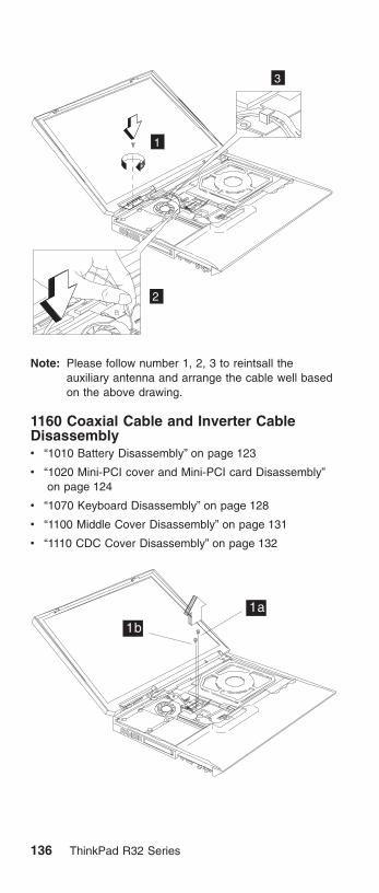
1
2
3
Note: Please follow number 1, 2, 3 to reintsall theauxiliary antenna and arrange the cable well basedon the above drawing.
1160 Coaxial Cable and Inverter CableDisassemblyv “1010 Battery Disassembly” on page 123
v “1020 Mini-PCI cover and Mini-PCI card Disassembly”on page 124
v “1070 Keyboard Disassembly” on page 128
v “1100 Middle Cover Disassembly” on page 131
v “1110 CDC Cover Disassembly” on page 132
1a
1b
136 ThinkPad R32 Series

Step Size (Quantity) Color Torque
1 M2.5 x L5 (2) Silver 2.5 kgf-cm
3 2
4
Note: Release the gray cable, which is the main antennafrom the system.
1170 LCD Disassemblyv “1010 Battery Disassembly” on page 123
v “1020 Mini-PCI cover and Mini-PCI card Disassembly”on page 124
v “1070 Keyboard Disassembly” on page 128
v “1100 Middle Cover Disassembly” on page 131
v “1110 CDC Cover Disassembly” on page 132
MT 2658/2659/2677 137

1a
1b1c
1d
Step Size (Quantity) Color Torque
1 M2.5 x L10 (4) Black 3.2 kgf-cm
2
1180 Keyboard bezel Disassemblyv “1010 Battery Disassembly” on page 123
v “1020 Mini-PCI cover and Mini-PCI card Disassembly”on page 124
v “1040 Hard Disk Drive Disassembly” on page 126
v “1070 Keyboard Disassembly” on page 128
v “1100 Middle Cover Disassembly” on page 131
v “1170 LCD Disassembly” on page 137
138 ThinkPad R32 Series

1
Step Size (Quantity) Color Torque
1 M2.5 x L10 (7) Black 3.2 kgf-cm
MT 2658/2659/2677 139

2
CAUTION:The keyboard bezel has several latches. Whenremoving the keyboard bezel from the bottom cover,gently release these latches, then raise the side of thekeyboard bezel facing the palm rest to remove it. Becareful not to break the latches.
1190 VGA Heat Sink Disassemblyv “1010 Battery Disassembly” on page 123
v “1020 Mini-PCI cover and Mini-PCI card Disassembly”on page 124
v “1040 Hard Disk Drive Disassembly” on page 126
v “1070 Keyboard Disassembly” on page 128
v “1090 Safety Cover Disassembly” on page 130
v “1100 Middle Cover Disassembly” on page 131
v “1170 LCD Disassembly” on page 137
v “1160 Coaxial Cable and Inverter Cable Disassembly”on page 136
v “1180 Keyboard bezel Disassembly” on page 138
140 ThinkPad R32 Series

1
Step Size (Quantity) Color Torque
1 M2.5 x L5 (1) Silver 2.5 kgf-cm
1200 PCMCIA Holder Disassemblyv “1010 Battery Disassembly” on page 123
v “1070 Keyboard Disassembly” on page 128
v “1030 Memory cover and Memory card Disassembly” onpage 125
1
MT 2658/2659/2677 141

2c2a
2b
2d
Step Size (Quantity) Color Torque
2 M2 x L6 (4) Silver 1.6 kgf-cm
3
Note: Before removing and replacing the PCMCIA holder,make sure that the PCMCIA cards are removed andthe eject levers are sticking out.
1210 Heat Sink Module Disassemblyv “1010 Battery Disassembly” on page 123
v “1070 Keyboard Disassembly” on page 128
v “1100 Middle Cover Disassembly” on page 131
142 ThinkPad R32 Series

1
1a
1b1c
1d
Step Size (Quantity) Color Torque
1 CPU SpecialScrew(4)
Silver 2.5 kgf-cm
Note: Thermal Pad must be replaced when either HeatSink Module, CPU or System Board is replaced.Thermal Pad is stuck on the bottom side of HeatSink Module with adhesive. Do not re-use thethermal pad.
1220 Fan Disassemblyv “1010 Battery Disassembly” on page 123
v “1070 Keyboard Disassembly” on page 128
v “1100 Middle Cover Disassembly” on page 131
MT 2658/2659/2677 143

1a
1b
1c
2
Step Size (Quantity) Color Torque
1 M2.5 x L5 (3) Silver 2.5 kgf-cm
1230 CPU Disassemblyv “1010 Battery Disassembly” on page 123
v “1070 Keyboard Disassembly” on page 128
v “1100 Middle Cover Disassembly” on page 131
v “1210 Heat Sink Module Disassembly” on page 142
1
144 ThinkPad R32 Series

2
Note: Thermal Pad must be replaced when either HeatSink Module, CPU or System Board is replaced.Thermal Pad is stuck on the bottom side of HeatSink Module with adhesive. Do not re-use thethermal pad.
1240 Speaker Disassemblyv “1010 Battery Disassembly” on page 123
v “1020 Mini-PCI cover and Mini-PCI card Disassembly”on page 124
v “1040 Hard Disk Drive Disassembly” on page 126
v “1070 Keyboard Disassembly” on page 128
v “1100 Middle Cover Disassembly” on page 131
v “1170 LCD Disassembly” on page 137
v “1180 Keyboard bezel Disassembly” on page 138
2
1
MT 2658/2659/2677 145

Step Size (Quantity) Color Torque
2 M2.5 x L5(1) Silver 2.5 kgf-cm
1250 System Board Disassemblyv “1010 Battery Disassembly” on page 123
v “1020 Mini-PCI cover and Mini-PCI card Disassembly”on page 124
v “1040 Hard Disk Drive Disassembly” on page 126
v “1060 CD-ROM Disassembly” on page 127
v “1070 Keyboard Disassembly” on page 128
v “1100 Middle Cover Disassembly” on page 131
v “1110 CDC Cover Disassembly” on page 132
v “1170 LCD Disassembly” on page 137
v “1180 Keyboard bezel Disassembly” on page 138
v “1240 Speaker Disassembly” on page 145
1
Step Size (Quantity) Color Torque
1 M2.5 x L5(2) Silver 2.5 kgf-cm
146 ThinkPad R32 Series

23
Notes:
1. When removing the system board from the bottomcover, gently raise the side of the system board facingthe rear I/O ports; then pull out the system board.
2. In step 2, further pull out this latch before the systemboard is attached to the lower case.
3. Thermal Pad must be replaced when either Heat SinkModule, CPU or System Board is replaced. ThermalPad is stuck on the bottom side of Heat Sink Modulewith adhesive. Do not re-use the thermal pad.
1260 I/O Port Bracket Disassemblyv “1010 Battery Disassembly” on page 123
v “1020 Mini-PCI cover and Mini-PCI card Disassembly”on page 124
v “1040 Hard Disk Drive Disassembly” on page 126
v “1060 CD-ROM Disassembly” on page 127
v “1070 Keyboard Disassembly” on page 128
v “1100 Middle Cover Disassembly” on page 131
v “1110 CDC Cover Disassembly” on page 132
v “1170 LCD Disassembly” on page 137
v “1180 Keyboard bezel Disassembly” on page 138
v “1240 Speaker Disassembly” on page 145
v “1250 System Board Disassembly” on page 146
MT 2658/2659/2677 147
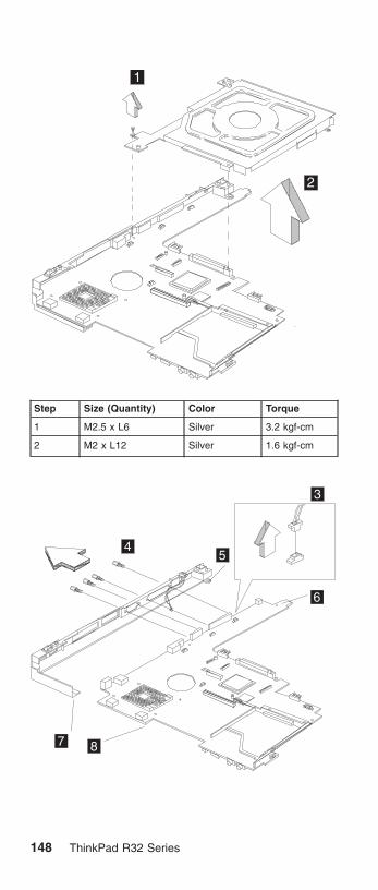
1
2
Step Size (Quantity) Color Torque
1 M2.5 x L6 Silver 3.2 kgf-cm
2 M2 x L12 Silver 1.6 kgf-cm
3
45
6
7 8
148 ThinkPad R32 Series

Step Size (Quantity) Color Torque
4 Hex Screw(4) Silver 2.5 kgf-cm
Note: When attaching the I/O port bracket to the systemboard, please pay special attention to the studs’positions as marked 5, 6, 7, 8. The one marked 5should be installed above the one marked 6; theone marked number 7 should be aligned with andattached beneath the one marked number 8.
CAUTION:There are several types of system board FRU for theThinkpad R32 series, as followed:
v System board with IBM security chip
a
v System board without IBM security chip
a
Begin by checking the FRU number of the systemboard, and be sure to use the correct system boardFRU for the computer. For the FRU numbers,see“Parts list” on page 161
MT 2658/2659/2677 149

ImportantIf the ThinkPad computer you are servicing has thesecurity chip, mind the following:
v Do not remove the security chip from thesystem board. If the security chip is removed byaccident, reintall it on the system boardimmediately. Then make sure that it is firmly fixedon the system board and does not remove easily.
v The security chip cannot be used with any othersystem board.
v The system board cannot be used with any othersecurity chip.
v The system board cannot be used withoutsecurity chip
v When you return the defective system boardFRU, you must check whether the security chip isfirmly attached to the system board. If it is notembedded, it may not be covered under warranty.
1270 LCD Bezel Disassembly (14.1″)v “1010 Battery Disassembly” on page 123
v “1020 Mini-PCI cover and Mini-PCI card Disassembly”on page 124
v “1070 Keyboard Disassembly” on page 128
v “1100 Middle Cover Disassembly” on page 131
v “1170 LCD Disassembly” on page 137
1
150 ThinkPad R32 Series

2
Step Size (Quantity) Color Torque
2 M2.5 x L6(2) Black 2.5 kgf-cm
3
3
4
5
6
7
Note: When removing the LCD, take note of the following:
v Be careful not to scratch the LCD bezel whenremoving the screw mylars.
v The LCD bezel has several latches. Releasethese latches; then remove the LCD bezel. Becareful not to break these latches.
v Gently push the two LCD latches outward toremove the LCD bezel.
1280 LCD Inveter Disassembly(14.1″)v “1010 Battery Disassembly” on page 123
v “1020 Mini-PCI cover and Mini-PCI card Disassembly”on page 124
v “1070 Keyboard Disassembly” on page 128
MT 2658/2659/2677 151

v “1100 Middle Cover Disassembly” on page 131
v “1170 LCD Disassembly” on page 137
v “1270 LCD Bezel Disassembly (14.1″)” on page 150
23
1a1b
Step Size (Quantity) Color Torque
1 M2 x L10(2) Black 2.5 kgf-cm
1290 LCD Board Disassembly(14.1″)v “1010 Battery Disassembly” on page 123
v “1020 Mini-PCI cover and Mini-PCI card Disassembly”on page 124
v “1070 Keyboard Disassembly” on page 128
v “1100 Middle Cover Disassembly” on page 131
v “1170 LCD Disassembly” on page 137
v “1270 LCD Bezel Disassembly (14.1″)” on page 150
v “1280 LCD Inveter Disassembly(14.1″)” on page 151
1
152 ThinkPad R32 Series

2
Step Size (Quantity) Color Torque
2 M2 x L4(2) Silver 2.5 kgf-cm
3a
3b
4
Step Size (Quantity) Color Torque
3 M2.5 x L6(2) Black 2.5 kgf-cm
MT 2658/2659/2677 153

Note: Before step 4 of removing the LED board, pleasemake sure the main antenna cable is lifted gently.
5
6
1300 LCD Bracket Hinges Disassembly(14.1″)v “1010 Battery Disassembly” on page 123
v “1020 Mini-PCI cover and Mini-PCI card Disassembly”on page 124
v “1070 Keyboard Disassembly” on page 128
154 ThinkPad R32 Series

v “1100 Middle Cover Disassembly” on page 131
v “1170 LCD Disassembly” on page 137
v “1270 LCD Bezel Disassembly (14.1″)” on page 150
v “1280 LCD Inveter Disassembly(14.1″)” on page 151
v “1290 LCD Board Disassembly(14.1″)” on page 152
1a1b
1c
1d
Step Size (Quantity) Color Torque
1 M2 x L4 (4) Silver 2.5 kgf-cm
1310 Main Antenna Disassembly(14.1″)v “1010 Battery Disassembly” on page 123
v “1020 Mini-PCI cover and Mini-PCI card Disassembly”on page 124
v “1070 Keyboard Disassembly” on page 128
v “1100 Middle Cover Disassembly” on page 131
v “1170 LCD Disassembly” on page 137
v “1270 LCD Bezel Disassembly (14.1″)” on page 150
v “1280 LCD Inveter Disassembly(14.1″)” on page 151
v “1290 LCD Board Disassembly(14.1″)” on page 152
v “1300 LCD Bracket Hinges Disassembly (14.1″)” onpage 154
MT 2658/2659/2677 155

1
Step Size (Quantity) Color Torque
1 M2 x L4(1) Silver 2.5 kgf-cm
1320 Main Antenna Cable Reassemblyv “1010 Battery Disassembly” on page 123
v “1020 Mini-PCI cover and Mini-PCI card Disassembly”on page 124
v “1070 Keyboard Disassembly” on page 128
v “1100 Middle Cover Disassembly” on page 131
v “1170 LCD Disassembly” on page 137
v “1270 LCD Bezel Disassembly (14.1″)” on page 150
v “1280 LCD Inveter Disassembly(14.1″)” on page 151
v “1290 LCD Board Disassembly(14.1″)” on page 152
v “1300 LCD Bracket Hinges Disassembly (14.1″)” onpage 154
156 ThinkPad R32 Series

1330 Mylar Assemblyv “1010 Battery Disassembly” on page 123
v “1020 Mini-PCI cover and Mini-PCI card Disassembly”on page 124
12
MT 2658/2659/2677 157

Locations
Front View
TrackPoint
System-status indicators
Computer display
Ultrabay Plus
Rear View
Power jack
Ethernet connectorMonitor connector
USB connector
TV port
Modem connectorParallel port
158 ThinkPad R32 Series

Bottom View
1
2
3
4
1. Battery pack
2. Memory slot door
3. Mini-PCI Card slot door
4. Docking connector
MT 2658/2659/2677 159

Switch Locations
SW2
Pin11 0
BootBlockDisabled
BootBlockEnabled
Pin2
CheckPasswordEnabled
1 0 1 0
CheckPasswordDisabled
01
160 ThinkPad R32 Series

Parts list
15
1
2
4
56
7
11
12
1314 16
17
18
19
21
9
20
10
8
23
22
3
8
Note: The parts marked with asterisk are CRUs (customerreplaceable units.)
MT 2658/2659/2677 161

There are two levels of CRUs: Tier 1 and Tier 2. Tier 1CRUs are identified by one asterisk (*). Tier 2 CRUs areidentified by 2 asterisks ( * *).
Tier 1 CRUs are defined as those CRUs that meet thefollowing criteria:
1. No tools required for removal or replacement.
Exception: Coin, thumb screws are acceptable.
2. Minimal technical expertise required.
3. Minimal Problem Determination is required (less than 5minutes).
Tier 2 CRUs are defined as those CRUs that meet thefollowing criteria:
1. Some screw/fastener removals.
2. Some technical experience required.
3. Helpcenter assistance may be used.
4. Problem Determination can be done by customers orwith Helpcenter assistance.
No. Description FRU No.
1 Hinge Cap 26P9722
LG/ IBM Logo Kit 08K5860
3 Middle Cover Asm 46L6509
4 Upper Case-KBD Bezel 46L6508
5 Antenna Kit for D-1.5 (w/ puller TABs) 08K4072
Antenna Kit 13″/14″ LCD for D-1.5 08K4073
6 Cable Asm. kit , RJ11 and lid switch 27L0722
7 Planar for Pentium-4M w/o securitycard, w/o 1394
26P8292
Planar for Pentium-4M w/ security card,w/ 1394
26P8341
Planar for Pentium-4M w/o securitycard, w/1394
26P8291
Planar for Pentium-4M w/ security card,w/o 1394
26P8343
8 M/B Misc parts kit 46P2586
9 PC Card Slot 46L6530
10 HDD w/tray & screws module IBMCsacard./ 20 GB
08K9761* *
HDD w/tray & screws module HITACHIDogwood/ 20GB
08K9763**
HDD w/tray & screws module IBMCsacard / 30 GB
08K9733**
HDD w/tray & screws module HITACHIDogwood/ 30GB
08K9746**
162 ThinkPad R32 Series

No. Description FRU No.
HDD w/tray & screws module IBMCsacard / 40 GB
08K9742**
HDD w/tray & screws module HITACHIDogwood/ 40GB
08K9774**
11 HDD Cover 46L6523
12 Lower Case w/ label W/W for WR 62P4051
Lower Case w/ label EMEA for WR 62P4052
Lower Case w/ label IIPC—Ciscowireless
62P4058
Lower Case w/ label Japan—Ciscowireless
62P4059
13 CARD ASM DDR- 128M 10K0029**
CARD ASM DDR- 256M 10K0031**
CARD ASM DDR- 512M 10K0033**
14 CDC Modem Card 26P8256
Cisco Aironet Wireless 802.11bMini-PCI-for North America
26P8435
Cisco Aironet Wireless 802.11bMini-PCI for EMEA
26P8367
Cisco Aironet Wireless 802.11bMini-PCI for China
26P8371
Cisco Aironet Wireless 802.11bMini-PCI for Japan
26P8369
15 Mini-PCI / DIMM door kit 46L6524
16 Main Battery Assy. (Li-Ion)
Sanyo-W/W
Sanyo-Japan
Panasonic-W/W
Panasonic-Japan
02K7054*
02K7058*
02K6928*
02K7060*
17 Speaker Kit 08K4618
18 RTC Battery(P/N 02K7063) 02K7062
19 CD-ROM Module
TEAC (CD-224E-B01)
LG (CRN-8245B)
27L3436*
27L4301*
DVD-ROM Module
Hitachi (GDR-8081N)
MKE (SR-8176–MBZ)
27L4355*
27L4351*
MT 2658/2659/2677 163

No. Description FRU No.
CD—RW Module
TEAC (CD-W28E-001)CD—RW /12XDVD Module
KME UJDA720
27L4297*
27L4359*
FDD External, Unit P/N 05K9282 05K9283*
Rubber Kit 46L6527
Mylar Kit 46P2589
Screw Kit 46L6526
Mylar-Antenna holder 46P3133
Base cover Misc parts kit 46P2587
20 FAN asm 46L6507
21 Heat Sink Asm. (w/ thermal pad) 46P2588
22 I/O Bracket 46P2590
23 CPU Intel Pentium-4M 1.6 GHz 26P8345
CPU Intel Pentium-4M 1.7 GHz 26P8449
CPU Intel Pentium-4M 1.8 GHz 26P8346
164 ThinkPad R32 Series

LCD FRU
13.3-inch TFT:
1
2
3
34
56
7
No. Description FRU No.
4 LCD Invertor / LED card 14/13″ TFT(P/N 26P8140)
26P8139
6 Antenna Kit for D-1.5 (w/ puller TABs) 08K4072
Antenna Kit 13″/14″ LCD for D-1.5 08K4073
7 LCD Rear Cover asm (13/14″TFT)-Wireless
26P9709
LCD Rear Cover asm (13/14″ TFT) 26P9707
MT 2658/2659/2677 165

14.1-inch TFT:
1
2
3
34
5
6
7
No. Description FRU No.
1 LCD Bezel asm ″R32″ (14″ TFT) 46L6503
2 LCD Panel asm (14″ TFT)
DBU
LG/LW
Samsung
05K9888
11P8283
11P8280
3 LCD Hinge/Bracket kit (14″ TFT) 26P9719
4 LCD Invertor / LED card 14/13″ TFT(P/N 26P8140)
26P8139
5 LCD cable asm (14″ TFT) 27L0720
6 Antenna Kit for D-1.5 (w/ puller TABs) 08K4072
Antenna Kit 13″/14″ LCD for D-1.5 08K4073
7 LCD Rear Cover asm (13/14″TFT)-Wireless
26P9709
LCD Rear Cover asm (13/14″ TFT) 26P9707
166 ThinkPad R32 Series

Keyboard
Description Vendor FRU No.
KBD ASM US English NMB 08K4506**
KBD ASM Canadian French NMB 08K4508**
KBD ASM German NMB 08K4510**
KBD ASM UK English NMB 08K4512**
KBD ASM French NMB 08K4514**
KBD ASM Dutch NMB 08K4516**
KBD ASM Swedish/Finnish NMB 08K4518**
KBD ASM Norwegian NMB 08K4520**
KBD ASM Danish NMB 08K4522**
KBD ASM Italian NMB 08K4524**
KBD ASM European Spanish NMB 08K4526**
KBD ASM Belgian NMB 08K4528**
KBD ASM Switzerland NMB 08K4530**
KBD ASM Portuguese NMB 08K4532**
KBD ASM Arabic NMB 08K4534**
KBD ASM Russian NMB 08K4536**
KBD ASM Hebrew NMB 08K4538**
KBD ASM Polish NMB 08K4540**
KBD ASM Turkish NMB 08K4542**
KBD ASM Czech NMB 08K4544**
KBD ASM Hungarian NMB 08K4546**
KBD ASM Greek NMB 08K4548**
KBD ASM Slovenian NMB 08K4550**
KBD ASM Slovakian NMB 08K4552**
KBD ASM Japanese NMB 08K4554**
KBD ASM Traditional Chinese NMB 08K4556**
KBD ASM Korean NMB 08K4558**
KBD ASM La Spanish NMB 08K4560**
KBD ASM US English Chicony 08K4562**
KBD ASM Canadian French Chicony 08K4564**
KBD ASM German Chicony 08K4566**
KBD ASM UK English Chicony 08K4568**
KBD ASM French Chicony 08K4570**
KBD ASM Dutch Chicony 08K4572**
KBD ASM Swedish/Finnish Chicony 08K4574**
KBD ASM Norwegian Chicony 08K4576**
KBD ASM Danish Chicony 08K4578**
KBD ASM Italian Chicony 08K4580**
KBD ASM European Spanish Chicony 08K4582**
MT 2658/2659/2677 167

Description Vendor FRU No.
KBD ASM Belgian Chicony 08K4584**
KBD ASM Switzerland Chicony 08K4586**
KBD ASM Portuguese Chicony 08K4588**
KBD ASM Arabic Chicony 08K4590**
KBD ASM Russian Chicony 08K4592**
KBD ASM Hebrew Chicony 08K4594**
KBD ASM Polish Chicony 08K4596**
KBD ASM Turkish Chicony 08K4598**
KBD ASM Czech Chicony 08K4600**
KBD ASM Hungarian Chicony 08K4602**
KBD ASM Greek Chicony 08K4604**
KBD ASM Slovenian Chicony 08K4606**
KBD ASM Slovakian Chicony 08K4608**
KBD ASM Japanese Chicony 08K4610**
KBD ASM Traditional Chinese Chicony 08K4612**
KBD ASM Korean Chicony 08K4614**
KBD ASM La Spanish Chicony 08K4616**
Common parts list
Tools:
Description FRU No.
Tri-Connector Wrap Plug 72X8546
PC Test Card 35G4703
Audio Wrap Cable 66G5180
USB Parallel Test Cable 05K2580
Screwdriver Kit 95F3598
5mm Socket Wrench 05K4694
Screwdriver 27L8126
Wireless Antenna Connector Tool 08K7159
ThinkPad hardware maintenance disketteversion 1.07
Note: The data may look the same with the sample hmmbut the diskette version is different. There is no FRUnumber for ThinkPad hardware maintenancediskette.
168 ThinkPad R32 Series

Telephone cable:
Description FRU No.
Telephone Cable (US/ CAN/ TWN/ APS/ LA/BRZL)
27L0465*
Telephone Cable (UK/ IR/ NZ) 27L0442*
Telephone Cable (GERMANY) 27L0441*
Telephone Cable (ITALY) 27L0448*
Telephone Cable (FRANCE) 27L0443*
Telephone Cable (DK/ DE/ PO) 27L0447*
Telephone Ccable (SW/ SU) 27L0445*
Telephone Cable (FI/ NO/ NS) 27L0446*
Telephone Cable (AUSTRALIA) 27L0467*
Telephone Cable (ND/NU) 27L0444*
Telephone Cable (SF/ SI/ SG/ SE) 27L0462*
Telephone Cable (BE/ BK/ BS/ BD/ BF) 27L0451*
Telephone Cable (AUSTRIA) 27L0449*
Telephone Cable (SPAIN) 27L0450*
AC adapter:
Description FRU No.
AC ADAPTER, 72W 3-pins (ASTEC) 02K6751*
AC ADAPTER, 72W 3-pins (Delta) 02K6754*
AC ADAPTER, 72W 2-pins (Delta) 02K6756*
AC ADAPTER, 72W 2-pinS (ASTEC) 02K6753*
Power cords: IBM power cords for a specific country areusually available only in that country.
For 2–pin power cords:
IBM powercord partnumber Used in these countries or regions
13H5264* Canada, U.S.A.
13H5273* Japan
36L8870* Argentina
49P2095* Brazil
For 3–pin power cords:
Note: The grounded adapter is required for full MPRIIcompliance. If a 3–pin power cord came with yourcomputer, see “Safety Information” on page 11.
MT 2658/2659/2677 169

IBM powercord partnumber Used in these countries or regions
76H3514* Australia, New Zealand
76H3516* Taiwan, Thailand
76H3530* Italy
76H3520* Denmark
76H3524* UK, Hong Kong
76H3518* European Countries
76H3522* South Africa, India
76H3532* Israel
76H3535* Korea
02K0539* China (P.R.C.)
76H3528* Switzerland
Recovery CD List:
Description FRU No. MODELS
Recovery CDEnglish-WinXP PRO(UD)
01R5611 2677–BZG:2659–CHG, BZG:2658–CHG, BZG
Revoery CDEnglish-WinXP PRO(US)
01R5610 2677–BZU:2659–CHU, BZU:2658–CHU, BZU
Revoery CDEnglish-WinXP PRO(US)
01R5610 2677–BZH:2659–CHH, BZH:2658–CHH, BZH
Revoery CDEnglish-WinXP PRO(US)
01R5610 2677–BZM:2659–CHM,BZM:2658–CHM,BZM
Revoery CDEnglish-WinXP PRO(US)
01R5610 2677–BZA:2659–BZA:2658–BZA
Recovery CDNorway-WinXP PRO
01R5621 2677–BZG:2659–CHG, BZG:2658–CHG, BZG
Recovery CDNetherland-WinXPPRO
01R5620 2677–BZG:2659–CHG, BZG:2658–CHG, BZG
Recovery CDFinland-WinXP PRO
01R5619 2677–BZG:2659–CHG, BZG:2658–CHG, BZG
Recovery CDItaly-WinXP PRO
01R5618 2677–BZG:2659–CHG, BZG:2658–CHG, BZG
Recovery CDSpanish-WinXPPRO
01R5616 2677–BZG:2659–CHG, BZG:2658–CHG, BZG
170 ThinkPad R32 Series

Recovery CDSpanish-WinXPPRO
01R5616 2677–BZX:2659–BZX:2658–BZX
Recovery CDSpanish-WinXPPRO
01R5616 2677–BZS:2659–BZS:2658–BZS
Recovery CDDenmark-WinXPPRO
01R5613 2677–BZG:2659–CHG, BZG:2658–CHG, BZG
Recovery CDSweden-WinXPPRO
01R5617 2677–BZG:2659–CHG, BZG:2658–CHG, BZG
Recovery CDFrench-WinXP PRO
01R5614 2677–BZG:2659–CHG, BZG:2658–CHG, BZG
Recovery CDFrench-WinXP PRO
01R5614 2677–BZF:2659–CHF, BZF:2658–CHF, BZF
Recovery CDGerman-WinXPPRO
01R5615 2677–BZG:2659–CHG, BZG:2658–CHG, BZG
RecoveryPortuguese-WinXPPRO
01R5612 2677–BZP:2659–BZP:2658–BZP
Recovery CDJapan-WinXP PRO
62P8912 2677–BZJ:2659–CHJ, BZJ:2658–CHJ, BZJ
Recovery CD HongKong-TC-WinXPPRO
67P4695 2677–BZB:2659–CHB, BZB:2658–CHB, BZB
Recovery CDTraditionalChinese-WinXPPRO
67P4693 2677–BZT:2659–BZT:2658–BZT
Recovery CDSimplifiedChinese-WinXPPRO
67P4694 2677–BZC:2659–CHC, BZC:2658–CHC, BZC
Recovery CDTurkey-WinXP PRO
01R5626 2677–BZG:2659–CHG, BZG:2658–CHG, BZG
Recovery CDGreek-WXP PRO
01R5627 2677–BZG:2659–CHG, BZG:2658–CHG, BZG
Recovery CDHungary-WinXPPRO
01R5628 2677–BZG:2659–CHG, BZG:2658–CHG, BZG
Recovery CDRussian-WinXPPRO
01R5629 2677–BZG:2659–CHG, BZG:2658–CHG, BZG
Recovery CDPolish-WinXP PRO
01R5625 2677–BZG:2659–CHG, BZG:2658–CHG, BZG
MT 2658/2659/2677 171

Recovery CDHebrew-WinXP PRO
01R5624 2677–BZG:2659–CHG, BZG:2658–CHG, BZG
Recovery CDCZ-WinXP PRO
01R5623 2677–BZG:2659–CHG, BZG:2658–CHG, BZG
Recovery CDEnglish-Win2000(US)
01R5670 2658–L6U, L7U,N7U, N8U
Recovery CDEnglish-Win2000(US)
01R5670 2658–N6A
Recovery CDSpanish-Win2000
01R5676 2658–N7S, N8S,L6S, L7S
Recovery CDSpanish-Win2000
01R5676 2658–N7X, N8X,L6X, L7X
Recovery CDPortuguese-Win2000
01R5672 2658–N7P, N8P,L6P, L7P
Recovery CDJapan-Win2000
62P8909 2658–K2J
Recovery CDEnglish-WinXPHOME (UD)
01R5731 2658–L8G, L9G
Recovery CDEnglish-WinXPHOME (US)
01R5730 2658–LCU, K3U,K4U, N9U, NGU,NHU
Recovery CDEnglish-WinXPHOME (US)
01R5730 2658–LAH, NEH,NFH: K4A, K5A:N9M
Recovery CDNorway-WinXPHOME
01R5741 2658–L8G, L9G
Recovery CDNetherland-WinXPHOME
01R5740 2658–L8G, L9G
Recovery CDFinland-WinXPHOME
01R5739 2658–L8G, L9G
Recovery CDItaly-WinXP HOME
01R5738 2658–L8G, L9G
Recovery CDSpanish-WinXPHOME
01R5736 2658–L8G, L9G
Recovery CDSpanish-WinXPHOME
01R5736 2658–K4S, N9S,NGS, NHS
Recovery CDSpanish-WinXPHOME
01R5736 2658–K4X, N9X,NGX, NHX
Recovery CDDenmark-WinXPHOME
01R5733 2658–L8G, L9G
172 ThinkPad R32 Series

Recovery CDSweden-WinXPHOME
01R5737 2658–L8G, L9G
Recovery CD WXPHOME
01R5734 2658–L8G, L9G
Recovery CDGerman-WinXPHOME
01R5735 2658–L8G, L9G
Recovery CDPortuguese-WinXPHOME
01R5732 2658–K4P, N9K,NGP, NHP
Recovery CDTurkey-WinXPHOME
01R5746 2658–L8G, L9G
Recovery CDGreek-WinXPHOME
01R5747 2658–L8G, L9G
Recovery CDHungary-WinXPHOME
01R5748 2658–L8G, L9G
Recovery CDRussian-WinXPHOME
01R5749 2658–L8G, L9G
Recovery CDPolish-WinXPHOME
01R5745 2658–L8G, L9G
Recovery CDHebrew-WinXPHOME
01R5744 2658–L8G, L9G
Recovery CDCZ-WinXP HOME
01R5743 2658–L8G, L9G
Option Parts List
Battery charges:
Description FRU No.
Main Battery Li-Ion Option—W/W 02K7052*
Main Battery Li-Ion Sanyo—W/W 02K7055*
Main Battery Li-Ion Panasonic—W/W 02K7057*
Main Battery Li-Ion Option—Japan 02K7053*
Main Battery Li-Ion Sanyo—Japan 02K7059*
Main Battery Li-Ion Panasonic—Japan 02K7061*
Ultrabay devices:
Description FRU No.
CD-RW/ DVD Combo II (KME) 27L4359*
CD-RW/ DVD Combo II (TEAC) 08K9785*
MT 2658/2659/2677 173

Description FRU No.
8X/ 4X/ 24X Max CD-RW (TEAC) 08K9644*
Ultralight 8X DVD-ROM (MKE) 27L4351*
Ultralight 8X DVD-ROM (HLDS) 27L4355*
24X-10X CD-ROM (HLDS) 27L4301*
24X-10X CD-ROM (TEAC) 27L3436*
Diskette drive (TEAC) 08K9606*
Diskette drive (SONY) 08K9607*
SuperDisk drive (LS240) 08K9615*
ZIP—250 drive 00N8254*
2nd HDD adapter 08K6067*
Ultrabay Plus device carrier 26P9388*
Ultrabay Plus numeric keypad 19K2056*
Ultrabay Plus cradle for WorkPad c500 series 26P9389*
174 ThinkPad R32 Series

ThinkPad R32 Series Part III
This section applies to the following models: 2677–J3X,2677–N3X, 2677–N4X, 2659–J3X, 2659–N3X, 2659–N4X,2659–N5X, 2658–J3X, 2658–N3X, 2658–N4X, 2658–N5X,2658–H4X, 2658–H3X, 2658–HAX, 2658–HBX, 2658–K3X,2658–K4X, 2658–K5X, 2658–K6X, 2658–K7X, 2658–K8X,2658–K9X, 2658–KAX, 2658–KBX, 2658–KCX, 2658–KDX,2658–KEX, 2658–MMX, 2658–KFX, 2658–2658–KGX,2658–KHX, 2658–KJX, 2658–MNX, 2658–MKX,2658–MLX, 2658–L7X, 2658–L8X, 2658–MPX, 2658–L9X,2658–LAX, 2658–LBX, 2658–LCX, 2658–LDX, 2658–LEX,2658–LFX, 2658–LGX, 2658–LHX, 2658–LJX, 2658–LKX,2658–LLX, 2658–LMX, 2658–LNX, 2658–LPX, 2658–LQX,2658–LRX, 2658–LSX, 2658–LTX, 2658–LUX, 2658–LVX,2658–LXX, 2658–LYX, 2658–LZX, 2658–M6X, 2658–M7X,2658–M9X, 2658–MAX, 2658–MBX, 2658–MHX,2658–MJX, 2658–MCX, 2658–MDX, 2658–MEX,2658–MFX, 2658–MGX, 2658–N6X, 2658–N9X,2658–NAX 2658–NBX, 2658–NCX, 2658–NDX,2658–NEX, 2658–NFX, 2658–NJX, 2658–NKX, 2658–NLX,2658–NMX, 2658–NPX, 2658–NQX, 2658–NRX,2658–NSX, 2658–NUX, 2658–NVX, 2658–NWX,2658–NXX, 2658–NYX, 2658–NZX
MT 2658/2659/2677 175

Product overviewThe following shows an overview of the system features.
Feature Description
Processor Intel Pentium-4M– 1.7GHz/ 1.8GHz/2.0GHz
Celeron 1.5GHz
Chip set Intel Brookdale (845MP)
Bus architecture Host bus 64 bits 266 MHz, PCI 32bits/33 MHz, ISA 16 bits/8.33MHz,PCMCIA 16 bits/33 MHz, Cardbus 32bits/32 MHz
System memory Two DDR DIMM Slots support 128MB,256MB, and 512MB DIMM card, up toMax. 1GB
Maximum frequency: PC 266 MHz
Maximum size: 1024 MB
CMOS RAM 256 bytes
Video ATI M6C graphics integrated V-RAMchip (8MB/16MB)
14.1– inch, 32 bit true colors,1024X768 pixel TFT XGA color LCD
Video memory 8/16MB V-RAM in video chip
LCD(Bright Ctrl) 13.3″ TFT (XGA)/ 14.1″ TFT (XGA)(KBD)
Audio AC97 audio based on the Intel ICH3AC link DMA engine
16– bit audio
Internal stereo speakers
Floppy Diskette drive(By model)
USB FDD External 1.44MB, 3.5 inchfloppy drive via USB interface(Bootable)
Hard disk drive-Upgradable
20GB, 30GB or 40GB, 2.5–inch9.5mm height, E-IDE interface
Ultrabay Plus 24X CD/ 8X DVD/ 8X, 4X, 24X MaxCD-RW/ CD-RW- DVD (Combo)/ BayBattery support, NEATS
Modem V.90 Soft modem (MDC or Livingstonemodem) Integrated CDC soft modemon the Intel ICH3 AC link DMA engine56 Kbps Data /Fax Modem.
Ethernet Intel Ethernet LOM
IEEE 1394 (on planar) On planar (Pop/ Depop) TiTSB43AB21 1394 controller on board
IEEE 1394.a 4–pin connector –nocable power 100 Mbps, 200 Mbps and400 Mbps.
176 ThinkPad R32 Series
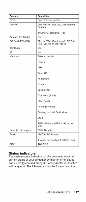
Feature Description
CDC One CDC slot (MDC)
Mini-PCI One Mini-PCI slot (802. 11b-ModemCombo)
or Mini-PCI slot (802. 11b)
Antenna (By Model) Yes
PC Card (PCMCIA) T2x1 or T3x1 (Cardbus w/o ZV Port)Two Type I/II or oneType III
ThinkLight Yes
IR Yes
I/O ports External monitor
Parallel
CRT
Two USB
Headphone
Mic-in
Speaker-out
Telephone (RJ11)
LAN (RJ45)
TV-out (S-Video)
Docking (for port Replicator)
DC-in
IEEE 1394 port (IEEE 1394 modeonly)
Security chip support TCPA Security
Power 72–Watt AC Adapter
8–cell Li-Ion Intelligent Battery Pack
BIOS IBM BIOS
Status indicatorsThe system-status indicators on the computer show thecurrent status of your computer by their on or off statesand colors (green and orange). Each indicator is identifiedwith a symbol. The following shows the location and the
MT 2658/2659/2677 177

meaning of each icon:
Symbol Color Meaning
(1) Drive in use Green Data is being read from orwritten to the hard disk. Donot enter standby mode orpower off the computerwhen this indicator is on.
(2) Numeric lock Green The numeric keypad on thekeyboard is enabled. Youenable or disable thekeypad by pressing andholding the Shift key, andpressing the NumLk key.For details, see the User’sReference.
(3) Caps lock Green Caps Lock mode isenabled. All alphabeticcharacters (A-Z) areentered in capital letterswithout the Shift key beingpressed. You enable ordisable the Caps Lockmode by pressing the CapsLock key.
(4) Scroll lock Green Scroll Lock mode isenabled. The Arrow keyscan be used asscreen-scroll function keys.The cursor cannot bemoved with the Arrowkeys. Not all applicationprograms support thisfunction. You enable ordisable Scroll Lock mode bypressing the ScrLk key.
178 ThinkPad R32 Series

Symbol Color Meaning
(5) Power on Green The computer isoperational. This indicator ison when the computer ison.
(6) Battery status Green Enough battery powerremains for operation.
Blinkinggreen
The battery power chargesup to 80% full power
Blinkingorange
The battery pack needs tobe charged
Orange The battery pack is beingcharged.
(7) Standby mode Green The computer is in standbymode
Symbol Color Meaning
(1) Battery status Green Enough battery powerremains for operation.
Blinkinggreen
The battery power chargesup to 80% full power
Blinkingorange
The battery pack needs tobe charged
Orange The battery pack is beingcharged.
(2) Standby mode Green The computer is in standbymode
MT 2658/2659/2677 179

FRU testsThe following table shows the applicable test for each FRUusing PC-Doctor.
FRU Applicable test
System board 1. CPU/Coprocessor (Diagnostics)
2. System board (Diagnostics)
Power Battery (Diagnostics)
LCD unit 1. Video Adapter (Diagnostics)
2. Video (Interactive Tests)
Modem 1. Make sure the modem set upcorrectly.
2. Replacing the modem jack andmodem card one at a time, run themodem tests in Other Devices(Diagnostics)
Audio Internal Speaker (Interactive Tests)
Stereo Speaker (Interactive Tests)
Speaker System beeper: Internal Speaker(Interactive Tests)
PC Card slots System board (Diagnostics)
Keyboard 1. Keyboard (Diagnostics)
2. Keyboard (Interactive Tests)
TrackPont or Pointingdevice
If the TrackPoint does not work, see if anexternal PS/2 mouse is connected to themouse/keyboard connector and removeit. The TrackPoint is automaticallydisabled if an external PS/2 mouse isattached. Check also if the TrackPointdriver is correctly installed by accessingWindows Device Manager via the Systemicon in the Control Panel.
After you use the TrackPoint, the pointerdrifts on the screen for a short time. Thisself-acting pointer movement can occurwhen a slight, steady pressure is appliedto the TrackPoint pointer. This symptomis not a hardware problem. No serviceactions are necessary if the pointermovement stops in a short period of time.
If this does not correct the TrackPointproblem, continue with the following:Mouse (Interactive Tests).
Hard disk drive Fixed Disks (Diagnostics)
CD-ROM drive CD-ROM, DVD, CD-RW, DVD/CD-RW(Interactive Tests)
180 ThinkPad R32 Series

FRU Applicable test
Memory 1. If a DIMM is installed, remove it andrun Memory Test-Quick (Diagnostics)
2. If the problem does not recur, replacethe DIMM and run the test again.
3. If the test does not detect the error,run Memory Test-Full (Diagnostics)
Fan 1. Power on system and check the airturbulence at the louver at the rear ofthe computer.
2. Run the fan test in Other Devices(Diagnostics).
MT 2658/2659/2677 181

FRU removals and replacementsThis section contains information about removals andreplacements.
v Do not damage any parts. Only certified and trainedpersonnel should service the computer.
v The arrows in this section show the direction ofmovement to remove a FRU, or to turn a screw torelease the FRU. The arrows are marked in numericorder, in square callout, to show the correct sequence ofremoval.
v Any FRUs that must be removed before removing thefailing FRU are listed at the top of the page.
v To replace a FRU, reverse the removal procedure andfollow any notes that pertain to replacement. See“Locations” on page 98 for internal cable connectionsand arrangement information.
v When replacing a FRU, use the correct screw size, asshown in the procedure.
Safety Notice 1Translations in ″Safety Notices (Multi-lingualTranslations)″ section: Before the computer ispowered-on after FRU replacement, make sure allscrews, springs, or other small parts are in placeand are not left loose inside the computer. Verifythis by shaking the computer and listening forrattling sounds. Metallic parts or metal flakes cancause electrical shorts.
Safety Notice 3Translations in ″Safety Notices (Multi-lingualTranslations)″ section: The battery pack containssmall amounts of nickel. Do not disassemble it,throw it into fire or water, or short-circuit it. Disposeof the battery pack as required by local ordinancesor regulations. Use only the battery in theappropriate parts listing when replacing the batterypack. Use of an incorrect battery can result inignition or explosion of the battery.
182 ThinkPad R32 Series

Safety Notice 8Translations in ″Safety Notices (Multi-lingualTranslations)″ section: Before removing any FRU,power-off the computer, unplug all power cords fromelectrical outlets, remove the battery pack, thendisconnect any interconnecting cables.
Attention: The system board is sensitive and can bedamaged by electronic discharge. Establish personalgrounding by touching a ground point with one hand beforetouching these units.
An electrostatic discharge (ESD) strap (P/N: 6405959)must be used to establish personal grounding.
Note: When disassembling the computer, pleasefollow the numerical and alphabetical orderssuch as 1a, 1b, 1c, 1d, 2, 3, 4. Please note thatwhen you assemble the computer, the sequencemarked in number and alphabets should berevervsed, for instance, 4, 3, 2, 1d, 1c, 1b, 1a.
1010 Battery Disassembly
21 2
WarningBattery packs are capable of delivering highcurrents for a significant amount of time. Do notshort the battery terminals.
CAUTION:Danger of explosion if battery is incorrectly replaced.Replace only with the same or equivalent typerecommended by the manufacturer. Dispose of usedbatteries according to the manufacturer’s instructions.
MT 2658/2659/2677 183

1020 Mini-PCI cover and Mini-PCI cardDisassemblyv “1010 Battery Disassembly” on page 183
1
2
Note: The screw does not separate from the PCI cover.
334
Note: There are 2 cables on step 4 : The gray cable is themain antenna and the black cable is the auxiliareyantenna. There is no step 3 if the Mini-PCI card isnot stalled, then this cable will be connected to the
184 ThinkPad R32 Series

CDC card.
Note: When you install the PCI card, remember to insert itinto its socket at 20°, press it down and ensure theconnection is well.
1030 Memory cover and Memory cardDisassemblyv “1010 Battery Disassembly” on page 183
1
2
MT 2658/2659/2677 185

Note: The screws do not separate from the memorycover.
1
2
To install the memory card:
With the notched end of the memory card toward the rightside of the socket, insert the memory card, at an angle ofapproximately 20°, into the socket; then press it firmly.Pivot the memory card until it snaps into place.
Side View
1040 Hard Disk Drive Disassemblyv “1010 Battery Disassembly” on page 183
186 ThinkPad R32 Series

1
2
Step Size (Quantity) Color Torque
1 M3 x L3.5 (1) Black 3.2 kgf-cm
WarningDo not drop or apply any shock to the hard diskdrive. The hard disk drive is sensitive to physicalshock. Incorrect handling can cause damage andpermanent loss of data on the drive.
Before removing the drive, have the user make abackup copy of all the information on the drive ifpossible.
Never remove the drive while the system isoperating or is in suspend mode.
1050 Hard Disk Drive Cover Disassemblyv “1010 Battery Disassembly” on page 183
1
1060 CD-ROM Disassemblyv “1010 Battery Disassembly” on page 183
MT 2658/2659/2677 187

1
2
3
1070 Keyboard Disassemblyv “1010 Battery Disassembly” on page 183
1a 1b
Step Size (Quantity) Color Torque
1 M2.5 x L10 (2) Black 3.2 kgf-cm
188 ThinkPad R32 Series

2
3
4
Notes:
1. When replacing the keyboard, make sure that the cableis clean and insert it directly into the connector, makingsure it makes contact with the bottom of the connector.
2. If the cable do not touch the bottom of the connector,the keyboard function will be rendered useless.
3. The cable of the keyboard are fragile and could bedamaged. Be careful when pulling out the cable.
1080 Backup Battery Disassemblyv “1010 Battery Disassembly” on page 183
v “1070 Keyboard Disassembly” on page 188
MT 2658/2659/2677 189

1
2
CAUTION:Danger of explosion if battery is incorrectly replaced.Replace only with the same or equivalent typerecommended by the manufacturer. Dispose of usedbatteries according to manufacturer’s instruction.
Safety Notice 4Translation in ″Safety Notices: Multi-lingualTranslations″ section: The backup battery is alithium battery and can cause a fire, an explosion, orsevere burns. Do not recharge it, remove itspolarized connector, disassemble it, heat it above100°C (212°F), incinerate it, or expose its cellcontents to water. Dispose of the battery as requiredby local ordinances or regulations. Use of anincorrect battery can result in ignition or explosion ofthe battery. Replacement batteries can be orderedfrom IBM or IBM Authorized Dealers.
1090 Safety Cover Disassemblyv “1010 Battery Disassembly” on page 183
v “1070 Keyboard Disassembly” on page 188
190 ThinkPad R32 Series

1
1100 Middle Cover Disassemblyv “1010 Battery Disassembly” on page 183
v “1070 Keyboard Disassembly” on page 188
1
2
MT 2658/2659/2677 191

4
Step Size (Quantity) Color Torque
2 M2.5 x L10 (1) Black 3.2 kgf-cm
4 M2.5 x L5 (1) Silver 2.5 kgf-cm
1110 CDC Cover Disassemblyv “1010 Battery Disassembly” on page 183
v “1020 Mini-PCI cover and Mini-PCI card Disassembly”on page 184
v “1070 Keyboard Disassembly” on page 188
v “1100 Middle Cover Disassembly” on page 191
1
Step Size (Quantity) Color Torque
1 M2.5 x L5 (1) Silver 2.5 kgf-cm
192 ThinkPad R32 Series

2
3
Notes:
1. If the Thinkpad R32 products are equipped with theMini-PCI card, then the CDC modem card will not beinstalled. The procedure of ″cdc-card″ referred aboveshould be skipped.
1120 Modem Cable Disassembly (WithoutCDC Modem Card)v “1010 Battery Disassembly” on page 183
v “1020 Mini-PCI cover and Mini-PCI card Disassembly”on page 184
v “1070 Keyboard Disassembly” on page 188
v “1100 Middle Cover Disassembly” on page 191
v “1110 CDC Cover Disassembly” on page 192
1
2
Notes:
1. If the Thinkpad R32 products are equipped with theMini-PCI card, the CDC modem card will not be
MT 2658/2659/2677 193

installed. The modem cable will then be connected tothe Mini-PCI card. Refer to ″Mini-PCI card″disassembly procedure to disconnect the modemcable.
1130 Modem Cable Disassembly (With CDCModem Card)v “1010 Battery Disassembly” on page 183
v “1070 Keyboard Disassembly” on page 188
v “1100 Middle Cover Disassembly” on page 191
v “1110 CDC Cover Disassembly” on page 192
1
Notes:
1. If the Thinkpad R32 products are equipped with theCDC modem card, the wireless LAN board will not beinstalled. The modem cable will then be connected tothe CDC modem card. Refer to ″CDC modem card″disassembly procedure to disconnect the modemcable.
1140 Auxiliary Antenna Disassemblyv “1010 Battery Disassembly” on page 183
v “1020 Mini-PCI cover and Mini-PCI card Disassembly”on page 184
v “1070 Keyboard Disassembly” on page 188
v “1100 Middle Cover Disassembly” on page 191
v “1110 CDC Cover Disassembly” on page 192
194 ThinkPad R32 Series

1
2
Step Size (Quantity) Color Torque
2 M2 x L2.5(1) Silver 2.0 kgf-cm
Note: Release the black cable, which is the auxiliaryantenna from the system.
1150 Auxiliary Antenna Reassemblyv “1010 Battery Disassembly” on page 183
v “1020 Mini-PCI cover and Mini-PCI card Disassembly”on page 184
v “1070 Keyboard Disassembly” on page 188
v “1100 Middle Cover Disassembly” on page 191
v “1110 CDC Cover Disassembly” on page 192
MT 2658/2659/2677 195

2
3
1
Note: Please follow number 1, 2, 3 to reintsall theauxiliary antenna and arrange the cable well basedon the above drawing.
1160 Coaxial Cable and Inverter CableDisassemblyv “1010 Battery Disassembly” on page 183
v “1020 Mini-PCI cover and Mini-PCI card Disassembly”on page 184
v “1070 Keyboard Disassembly” on page 188
v “1100 Middle Cover Disassembly” on page 191
v “1110 CDC Cover Disassembly” on page 192
1a
1b
196 ThinkPad R32 Series

Step Size (Quantity) Color Torque
1 M2.5 x L5 (2) Silver 2.5 kgf-cm
3 2
4
Note: Release the gray cable, which is the main antennafrom the system.
1170 LCD Disassemblyv “1010 Battery Disassembly” on page 183
v “1020 Mini-PCI cover and Mini-PCI card Disassembly”on page 184
v “1070 Keyboard Disassembly” on page 188
v “1100 Middle Cover Disassembly” on page 191
v “1110 CDC Cover Disassembly” on page 192
MT 2658/2659/2677 197

2
Step Size (Quantity) Color Torque
1 M2.5 x L10 (4) Black 3.2 kgf-cm
1a
1b1c
1d
1180 Keyboard bezel Disassemblyv “1010 Battery Disassembly” on page 183
v “1020 Mini-PCI cover and Mini-PCI card Disassembly”on page 184
v “1040 Hard Disk Drive Disassembly” on page 186
v “1070 Keyboard Disassembly” on page 188
v “1100 Middle Cover Disassembly” on page 191
v “1170 LCD Disassembly” on page 197
198 ThinkPad R32 Series

1
Step Size (Quantity) Color Torque
1 M2.5 x L10 (7) Black 3.2 kgf-cm
MT 2658/2659/2677 199

2
CAUTION:The keyboard bezel has several latches. Whenremoving the keyboard bezel from the bottom cover,gently release these latches, then raise the side of thekeyboard bezel facing the palm rest to remove it. Becareful not to break the latches.
1190 VGA Heat Sink Disassemblyv “1010 Battery Disassembly” on page 183
v “1020 Mini-PCI cover and Mini-PCI card Disassembly”on page 184
v “1040 Hard Disk Drive Disassembly” on page 186
v “1070 Keyboard Disassembly” on page 188
v “1090 Safety Cover Disassembly” on page 190
v “1100 Middle Cover Disassembly” on page 191
v “1170 LCD Disassembly” on page 197
v “1160 Coaxial Cable and Inverter Cable Disassembly”on page 196
v “1180 Keyboard bezel Disassembly” on page 198
200 ThinkPad R32 Series

1
Step Size (Quantity) Color Torque
1 M2.5 x L5 (1) Silver 2.5 kgf-cm
1200 PCMCIA Holder Disassemblyv “1010 Battery Disassembly” on page 183
v “1070 Keyboard Disassembly” on page 188
v “1030 Memory cover and Memory card Disassembly” onpage 185
1
MT 2658/2659/2677 201
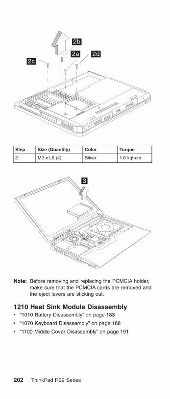
2c2a
2b
2d
Step Size (Quantity) Color Torque
2 M2 x L6 (4) Silver 1.6 kgf-cm
3
Note: Before removing and replacing the PCMCIA holder,make sure that the PCMCIA cards are removed andthe eject levers are sticking out.
1210 Heat Sink Module Disassemblyv “1010 Battery Disassembly” on page 183
v “1070 Keyboard Disassembly” on page 188
v “1100 Middle Cover Disassembly” on page 191
202 ThinkPad R32 Series

1
1a
1b1c
1d
Step Size (Quantity) Color Torque
1 CPU SpecialScrew(4)
Silver 2.5 kgf-cm
Note: Thermal Pad must be replaced when either HeatSink Module, CPU or System Board is replaced.Thermal Pad is stuck on the bottom side of HeatSink Module with adhesive. Do not re-use thethermal pad.
1220 Fan Disassemblyv “1010 Battery Disassembly” on page 183
v “1070 Keyboard Disassembly” on page 188
v “1100 Middle Cover Disassembly” on page 191
MT 2658/2659/2677 203
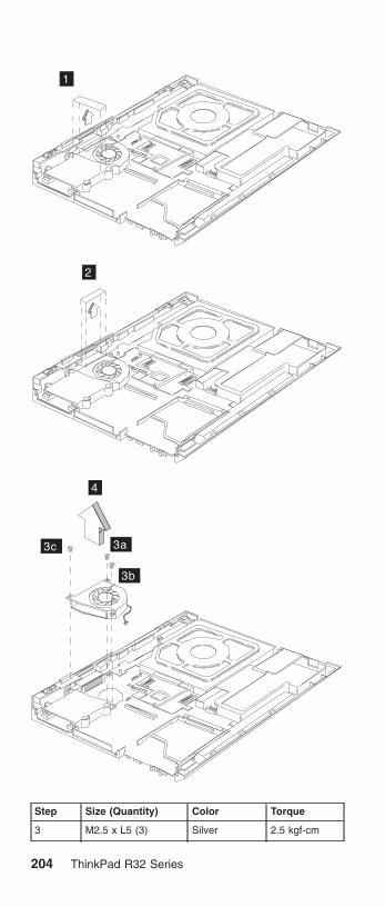
1
2
3a
3b
3c
4
Step Size (Quantity) Color Torque
3 M2.5 x L5 (3) Silver 2.5 kgf-cm
204 ThinkPad R32 Series

1230 CPU Disassemblyv “1010 Battery Disassembly” on page 183
v “1070 Keyboard Disassembly” on page 188
v “1100 Middle Cover Disassembly” on page 191
v “1210 Heat Sink Module Disassembly” on page 202
1
2
Note: Thermal Pad must be replaced when either HeatSink Module, CPU or System Board is replaced.Thermal Pad is stuck on the bottom side of HeatSink Module with adhesive. Do not re-use thethermal pad.
1240 Speaker Disassemblyv “1010 Battery Disassembly” on page 183
MT 2658/2659/2677 205

v “1020 Mini-PCI cover and Mini-PCI card Disassembly”on page 184
v “1040 Hard Disk Drive Disassembly” on page 186
v “1070 Keyboard Disassembly” on page 188
v “1100 Middle Cover Disassembly” on page 191
v “1170 LCD Disassembly” on page 197
v “1180 Keyboard bezel Disassembly” on page 198
2
1
Step Size (Quantity) Color Torque
2 M2.5 x L5(1) Silver 2.5 kgf-cm
1250 System Board Disassemblyv “1010 Battery Disassembly” on page 123
v “1020 Mini-PCI cover and Mini-PCI card Disassembly”on page 184
v “1040 Hard Disk Drive Disassembly” on page 186
v “1060 CD-ROM Disassembly” on page 187
v “1070 Keyboard Disassembly” on page 188
v “1100 Middle Cover Disassembly” on page 191
v “1110 CDC Cover Disassembly” on page 192
v “1170 LCD Disassembly” on page 197
v “1180 Keyboard bezel Disassembly” on page 198
v “1240 Speaker Disassembly” on page 205
206 ThinkPad R32 Series

1
Step Size (Quantity) Color Torque
1 M2.5 x L5(2) Silver 2.5 kgf-cm
23
Notes:
1. When removing the system board from the bottomcover, gently raise the side of the system board facingthe rear I/O ports; then pull out the system board.
MT 2658/2659/2677 207

2. In step 2, further pull out this latch before the systemboard is attached to the lower case.
3. Thermal Pad must be replaced when either Heat SinkModule, CPU or System Board is replaced. ThermalPad is stuck on the bottom side of Heat Sink Modulewith adhesive. Do not re-use the thermal pad.
1260 I/O Port Bracket Disassemblyv “1010 Battery Disassembly” on page 183
v “1020 Mini-PCI cover and Mini-PCI card Disassembly”on page 184
v “1040 Hard Disk Drive Disassembly” on page 186
v “1060 CD-ROM Disassembly” on page 187
v “1070 Keyboard Disassembly” on page 188
v “1100 Middle Cover Disassembly” on page 191
v “1110 CDC Cover Disassembly” on page 192
v “1170 LCD Disassembly” on page 197
v “1180 Keyboard bezel Disassembly” on page 198
v “1240 Speaker Disassembly” on page 205
v “1250 System Board Disassembly” on page 206
1
2
Step Size (Quantity) Color Torque
1 M2.5 x L6 Silver 3.2 kgf-cm
2 M2 x L12 Silver 1.6 kgf-cm
208 ThinkPad R32 Series

3
45
6
7 8
Step Size (Quantity) Color Torque
4 Hex Screw(4) Silver 2.5 kgf-cm
Note: When attaching the I/O port bracket to the systemboard, please pay special attention to the studs’positions as marked 5, 6, 7, 8. The one marked 5should be installed above the one marked 6; theone marked number 7 should be aligned with andattached beneath the one marked number 8.
MT 2658/2659/2677 209

CAUTION:There are several types of system board FRU for theThinkpad R32 series, as followed:
v System board with IBM security chip
a
v System board without IBM security chip
a
Begin by checking the FRU number of the systemboard, and be sure to use the correct system boardFRU for the computer. For the FRU numbers,see“Parts list” on page 161
210 ThinkPad R32 Series

ImportantIf the ThinkPad computer you are servicing has thesecurity chip, mind the following:
v Do not remove the security chip from thesystem board. If the security chip is removed byaccident, reintall it on the system boardimmediately. Then make sure that it is firmly fixedon the system board and does not remove easily.
v The security chip cannot be used with any othersystem board.
v The system board cannot be used with any othersecurity chip.
v The system board cannot be used withoutsecurity chip
v When you return the defective system boardFRU, you must check whether the security chip isfirmly attached to the system board. If it is notembedded, it may not be covered under warranty.
1270 LCD Bezel Disassembly (14.1″)v “1010 Battery Disassembly” on page 183
v “1020 Mini-PCI cover and Mini-PCI card Disassembly”on page 184
v “1070 Keyboard Disassembly” on page 188
v “1100 Middle Cover Disassembly” on page 191
v “1170 LCD Disassembly” on page 197
1
MT 2658/2659/2677 211

2
Step Size (Quantity) Color Torque
2 M2.5 x L6(2) Black 2.5 kgf-cm
3
3
4
5
6
7
Note: When removing the LCD, take note of the following:
v Be careful not to scratch the LCD bezel whenremoving the screw mylars.
v The LCD bezel has several latches. Releasethese latches; then remove the LCD bezel. Becareful not to break these latches.
v Gently push the two LCD latches outward toremove the LCD bezel.
1280 LCD Inveter Disassembly(14.1″)v “1010 Battery Disassembly” on page 183
v “1020 Mini-PCI cover and Mini-PCI card Disassembly”on page 184
v “1070 Keyboard Disassembly” on page 188
212 ThinkPad R32 Series

v “1100 Middle Cover Disassembly” on page 191
v “1170 LCD Disassembly” on page 197
v “1270 LCD Bezel Disassembly (14.1″)” on page 211
23
1a1b
Step Size (Quantity) Color Torque
1 M2 x L10(2) Black 2.5 kgf-cm
1290 LCD Board Disassembly(14.1″)v “1010 Battery Disassembly” on page 183
v “1020 Mini-PCI cover and Mini-PCI card Disassembly”on page 184
v “1070 Keyboard Disassembly” on page 188
v “1100 Middle Cover Disassembly” on page 191
v “1170 LCD Disassembly” on page 197
v “1270 LCD Bezel Disassembly (14.1″)” on page 211
v “1280 LCD Inveter Disassembly(14.1″)” on page 212
1
MT 2658/2659/2677 213

2
Step Size (Quantity) Color Torque
2 M2 x L4(2) Silver 2.5 kgf-cm
3a
3b
4
Step Size (Quantity) Color Torque
3 M2.5 x L6(2) Black 2.5 kgf-cm
214 ThinkPad R32 Series

Note: Before step 4 of removing the LED board, pleasemake sure the main antenna cable is lifted gently.
5
6
1300 LCD Bracket Hinges Disassembly(14.1″)v “1010 Battery Disassembly” on page 183
v “1020 Mini-PCI cover and Mini-PCI card Disassembly”on page 184
v “1070 Keyboard Disassembly” on page 188
MT 2658/2659/2677 215

v “1100 Middle Cover Disassembly” on page 191
v “1170 LCD Disassembly” on page 197
v “1270 LCD Bezel Disassembly (14.1″)” on page 211
v “1280 LCD Inveter Disassembly(14.1″)” on page 212
v “1290 LCD Board Disassembly(14.1″)” on page 213
1a1b
1c
1d
Step Size (Quantity) Color Torque
1 M2 x L4 (4) Silver 2.5 kgf-cm
1310 Main Antenna Disassembly(14.1″)v “1010 Battery Disassembly” on page 183
v “1020 Mini-PCI cover and Mini-PCI card Disassembly”on page 184
v “1070 Keyboard Disassembly” on page 188
v “1100 Middle Cover Disassembly” on page 191
v “1170 LCD Disassembly” on page 197
v “1270 LCD Bezel Disassembly (14.1″)” on page 211
v “1280 LCD Inveter Disassembly(14.1″)” on page 212
v “1290 LCD Board Disassembly(14.1″)” on page 213
v “1300 LCD Bracket Hinges Disassembly (14.1″)” onpage 215
216 ThinkPad R32 Series

1
Step Size (Quantity) Color Torque
1 M2 x L4(1) Silver 2.5 kgf-cm
1320 Main Antenna Cable Reassemblyv “1010 Battery Disassembly” on page 183
v “1020 Mini-PCI cover and Mini-PCI card Disassembly”on page 184
v “1070 Keyboard Disassembly” on page 188
v “1100 Middle Cover Disassembly” on page 191
v “1170 LCD Disassembly” on page 197
v “1270 LCD Bezel Disassembly (14.1″)” on page 211
v “1280 LCD Inveter Disassembly(14.1″)” on page 212
v “1290 LCD Board Disassembly(14.1″)” on page 213
v “1300 LCD Bracket Hinges Disassembly (14.1″)” onpage 215
MT 2658/2659/2677 217

1330 Mylar Assemblyv “1010 Battery Disassembly” on page 183
v “1020 Mini-PCI cover and Mini-PCI card Disassembly”on page 184
12
218 ThinkPad R32 Series

Locations
Front View
TrackPoint
System-status indicators
Computer display
Ultrabay Plus
Rear View
Power jack
Ethernet connectorMonitor connector
USB connector
TV port
Modem connectorParallel port
MT 2658/2659/2677 219
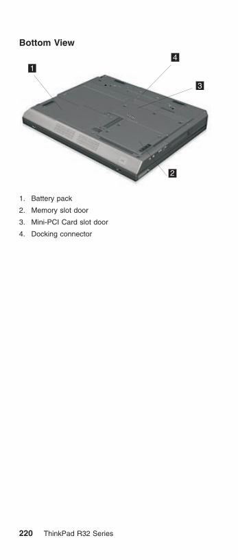
Bottom View
1
2
3
4
1. Battery pack
2. Memory slot door
3. Mini-PCI Card slot door
4. Docking connector
220 ThinkPad R32 Series
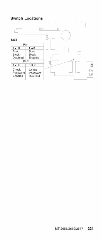
Switch Locations
SW2
Pin11 0
BootBlockDisabled
BootBlockEnabled
Pin2
CheckPasswordEnabled
1 0 1 0
CheckPasswordDisabled
01
MT 2658/2659/2677 221

Parts list
15
1
2
4
56
7
11
12
1314 16
17
18
19
21
9
20
10
8
23
22
3
8
Note: The parts marked with asterisk are CRUs (customerreplaceable units.)
222 ThinkPad R32 Series

There are two levels of CRUs: Tier 1 and Tier 2. Tier 1CRUs are identified by one asterisk (*). Tier 2 CRUs areidentified by 2 asterisks ( * *).
Tier 1 CRUs are defined as those CRUs that meet thefollowing criteria:
1. No tools required for removal or replacement.
Exception: Coin, thumb screws are acceptable.
2. Minimal technical expertise required.
3. Minimal Problem Determination is required (less than 5minutes).
Tier 2 CRUs are defined as those CRUs that meet thefollowing criteria:
1. Some screw/fastener removals.
2. Some technical experience required.
3. Helpcenter assistance may be used.
4. Problem Determination can be done by customers orwith Helpcenter assistance.
No. Description FRU No.
1 Hinge Cap 26P9722
LG/ IBM Logo Kit 08K5860
3 Middle Cover Asm 46L6509
4 Upper Case-KBD Bezel 62P4147
5 Antenna Kit for D-1.5 (w/ puller TABs) 08K4072
Antenna Kit 13″/14″ LCD for D-1.5 08K4073
6 Cable Asm. kit , RJ11 and lid switch 27L0722
7 Planar D-2 for Pentium-4M w/o securitycard, w/ 1394
26P8451
Planar D-2 for Pentium-4M w/o securitycard, w/o1394
26P8452
Planar D-2 for Pentium-4M w/ securitycard, w/ 1394
26P8453
Planar D-2 for Pentium-4M w/ securitycard, w/o 1394
26P8454
8 M/B Misc parts kit 62P4301
9 PC Card Slot 46L6530
10 HDD w/tray & screws module IBMCsacard./ 20 GB
08K9761* *
HDD w/tray & screws module HITACHIDogwood/ 20GB
08K9763**
HDD w/tray & screws module IBMCsacard / 30 GB
08K9733**
HDD w/tray & screws module HITACHIDogwood/ 30GB
08K9746**
MT 2658/2659/2677 223

No. Description FRU No.
HDD w/tray & screws module IBMCsacard / 40 GB
08K9742**
HDD w/tray & screws module HITACHIDogwood/ 40GB
08K9774**
11 HDD Cover 46L6523
12 Lower Case w/ label W/W for D-2 62P4148
Lower Case w/ label EMEA for D-2 62P4149
Lower Case w/ label IIPC for D-2 62P4150
Lower Case w/ label Korea for D-2 62P4151
Lower Case w/ label Taiwan for D-2 62P4152
Lower Case w/ label W/W-wireless forD-2
62P4153
Lower Case w/ label EMEA-wireless forD-2
62P4154
Lower Case w/ label IIPC-wireless forD-2
62P4155
Lower Case w/ label Korea-wireless forD-2
62P4156
Lower Case w/ label Taiwan for D-2 62P4157
Lower Case w/ label NA for D-2 62P4158
Lower Case w/ label EU for D-2 62P4159
Lower Case w/ label JP for D-2 62P4160
Lower Case w/ label China for D-2 62P4161
13 CARD ASM DDR- 128M 10K0029**
CARD ASM DDR- 256M 10K0031**
CARD ASM DDR- 512M 10K0033**
14 CDC Modem Card 26P8256
Cisco Aironet Wireless 802.11bMini-PCI-for North America
26P8435
Cisco Aironet Wireless 802.11bMini-PCI for EMEA
26P8367
Cisco Aironet Wireless 802.11bMini-PCI for China
26P8371
Cisco Aironet Wireless 802.11bMini-PCI for Japan
26P8369
IBM High Rate Wireless Mini-PCIAdapter
26P8472
15 Mini-PCI / DIMM door kit for D-2 62P4164
16 Main Battery Assy. (Li-Ion)
Sanyo-W/W
Sanyo-Japan
Panasonic-W/W
Panasonic-Japan
02K7054*
02K7058*
02K6928*
02K7060*
224 ThinkPad R32 Series

No. Description FRU No.
17 Speaker Kit 08K4618
18 RTC Battery(P/N 02K7063) 02K7062
19 CD-ROM Module
TEAC (CD-224E-B01)
LG (CRN-8245B)
27L3436*
27L4301*
DVD-ROM Module
Hitachi (GDR-8081N)
MKE (SR-8176–MBZ)
27L4355*
27L4351*
CD—RW Module
TEAC (CD-W28E-001)CD—RW /12XDVD Module
KME UJDA720
TEAC/ DW-28E-01 (2nd source)
27L4297*
27L4359*
08K9785*
FDD External, Unit P/N 05K9282 05K9283*
Rubber Kit 46L6527
Mylar Kit for D-2 62P4163
Screw Kit 46L6526
Mylar-Antenna holder 46P3133
Base cover Misc parts kit 46P2587
20 FAN asm 46L6507
21 Heat Sink/ FAN Asm. (w/ thermal pad)for D-2
62P4162
22 I/O Bracket 46P2590
23 CPU Intel Pentium-4M 1.7 GHz 26P8449
CPU Intel Pentium-4M 1.8 GHz 26P8346
CPU Intel Pentium-4M 2.0 GHz 26P8473
CPU Celeron 1.5GHz 26P8469
MT 2658/2659/2677 225
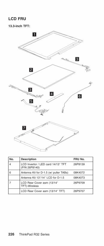
LCD FRU
13.3-inch TFT:
1
2
3
34
56
7
No. Description FRU No.
4 LCD Invertor / LED card 14/13″ TFT(P/N 26P8140)
26P8139
6 Antenna Kit for D-1.5 (w/ puller TABs) 08K4072
Antenna Kit 13″/14″ LCD for D-1.5 08K4073
7 LCD Rear Cover asm (13/14″TFT)-Wireless
26P9709
LCD Rear Cover asm (13/14″ TFT) 26P9707
226 ThinkPad R32 Series

14.1-inch TFT:
1
2
3
34
5
6
7
No. Description FRU No.
1 LCD Bezel asm ″R32″ (14″ TFT) 46L6503
2 LCD Panel asm (14″ TFT)
DBU
LG/LW
Samsung
05K9888
11P8283
11P8280
3 LCD Hinge/Bracket kit (14″ TFT) 26P9719
4 LCD Invertor / LED card 14/13″ TFT(P/N 26P8140)
26P8139
5 LCD cable asm (14″ TFT) 27L0720
6 Antenna Kit for D-1.5 (w/ puller TABs) 08K4072
Antenna Kit 13″/14″ LCD for D-1.5 08K4073
7 LCD Rear Cover asm (13/14″TFT)-Wireless
26P9709
LCD Rear Cover asm (13/14″ TFT) 26P9707
MT 2658/2659/2677 227

Keyboard
Description Vendor FRU No.
KBD ASM US English NMB 08K4506**
KBD ASM Canadian French NMB 08K4508**
KBD ASM German NMB 08K4510**
KBD ASM UK English NMB 08K4512**
KBD ASM French NMB 08K4514**
KBD ASM Dutch NMB 08K4516**
KBD ASM Swedish/Finnish NMB 08K4518**
KBD ASM Norwegian NMB 08K4520**
KBD ASM Danish NMB 08K4522**
KBD ASM Italian NMB 08K4524**
KBD ASM European Spanish NMB 08K4526**
KBD ASM Belgian NMB 08K4528**
KBD ASM Switzerland NMB 08K4530**
KBD ASM Portuguese NMB 08K4532**
KBD ASM Arabic NMB 08K4534**
KBD ASM Russian NMB 08K4536**
KBD ASM Hebrew NMB 08K4538**
KBD ASM Polish NMB 08K4540**
KBD ASM Turkish NMB 08K4542**
KBD ASM Czech NMB 08K4544**
KBD ASM Hungarian NMB 08K4546**
KBD ASM Greek NMB 08K4548**
KBD ASM Slovenian NMB 08K4550**
KBD ASM Slovakian NMB 08K4552**
KBD ASM Japanese NMB 08K4554**
KBD ASM Traditional Chinese NMB 08K4556**
KBD ASM Korean NMB 08K4558**
KBD ASM La Spanish NMB 08K4560**
KBD ASM US English Chicony 08K4562**
KBD ASM Canadian French Chicony 08K4564**
KBD ASM German Chicony 08K4566**
KBD ASM UK English Chicony 08K4568**
KBD ASM French Chicony 08K4570**
KBD ASM Dutch Chicony 08K4572**
KBD ASM Swedish/Finnish Chicony 08K4574**
KBD ASM Norwegian Chicony 08K4576**
KBD ASM Danish Chicony 08K4578**
KBD ASM Italian Chicony 08K4580**
KBD ASM European Spanish Chicony 08K4582**
228 ThinkPad R32 Series

Description Vendor FRU No.
KBD ASM Belgian Chicony 08K4584**
KBD ASM Switzerland Chicony 08K4586**
KBD ASM Portuguese Chicony 08K4588**
KBD ASM Arabic Chicony 08K4590**
KBD ASM Russian Chicony 08K4592**
KBD ASM Hebrew Chicony 08K4594**
KBD ASM Polish Chicony 08K4596**
KBD ASM Turkish Chicony 08K4598**
KBD ASM Czech Chicony 08K4600**
KBD ASM Hungarian Chicony 08K4602**
KBD ASM Greek Chicony 08K4604**
KBD ASM Slovenian Chicony 08K4606**
KBD ASM Slovakian Chicony 08K4608**
KBD ASM Japanese Chicony 08K4610**
KBD ASM Traditional Chinese Chicony 08K4612**
KBD ASM Korean Chicony 08K4614**
KBD ASM La Spanish Chicony 08K4616**
Common parts list
Tools:
Description FRU No.
Tri-Connector Wrap Plug 72X8546
PC Test Card 35G4703
Audio Wrap Cable 66G5180
USB Parallel Test Cable 05K2580
Screwdriver Kit 95F3598
5mm Socket Wrench 05K4694
Screwdriver 27L8126
Wireless Antenna Connector Tool 08K7159
ThinkPad hardware maintenance disketteversion 1.07
Note: The data may look the same with the sample hmmbut the diskette version is different. There is no FRUnumber for ThinkPad hardware maintenancediskette.
MT 2658/2659/2677 229

Telephone cable:
Description FRU No.
Telephone Cable (US/ CAN/ TWN/ APS/ LA/BRZL)
27L0465*
Telephone Cable (UK/ IR/ NZ) 27L0442*
Telephone Cable (GERMANY) 27L0441*
Telephone Cable (ITALY) 27L0448*
Telephone Cable (FRANCE) 27L0443*
Telephone Cable (DK/ DE/ PO) 27L0447*
Telephone Ccable (SW/ SU) 27L0445*
Telephone Cable (FI/ NO/ NS) 27L0446*
Telephone Cable (AUSTRALIA) 27L0467*
Telephone Cable (ND/ NU) 27L0444*
Telephone Cable (SF/ SI/ SG/ SE) 27L0462*
Telephone Cable (BE/ BK/ BS/ BD/ BF) 27L0451*
Telephone Cable (AUSTRIA) 27L0449*
Telephone Cable (SPAIN) 27L0450*
AC adapter:
Description FRU No.
AC ADAPTER, 72W 3-pins (ASTEC) 02K6751*
AC ADAPTER, 72W 3-pins (Delta) 02K6754*
AC ADAPTER, 72W 2-pins (Delta) 02K6756*
AC ADAPTER, 72W 2-pinS (ASTEC) 02K6753*
Power cords: IBM power cords for a specific country areusually available only in that country.
For 2–pin power cords:
IBM powercord partnumber Used in these countries or regions
13H5264* Canada, U.S.A.
13H5273* Japan
36L8870* Argentina
46P2095* Brazil
For 3–pin power cords:
Note: The grounded adapter is required for full MPRIIcompliance. If a 3–pin power cord came with yourcomputer, see “Safety Information” on page 11.
230 ThinkPad R32 Series

IBM powercord partnumber Used in these countries or regions
76H3514* Australia, New Zealand
76H3516* Taiwan, Thailand
76H3530* Italy
76H3520* Denmark
76H3524* UK, Hong Kong
76H3518* European Countries
76H3522* South Africa, India
76H3532* Israel
76H3535* Korea
02K0539* China (P.R.C.)
76H3528* Switzerland
Recovery CD List:
Description FRU No. MODELS
Recovery CDEnglish-WinXP PRO(UD)
01R6094 2677– L2G, L3G,L4G, L5G, N2G,N3G, N4G, N5G
Recovery CDEnglish-WinXP PRO(UD)
01R6094 2659 L2G, L3G,L4G, L5G, N2G,N3G, N4G, N5G,H2G
Recovery CDEnglish-WinXP PRO(UD)
01R6094 2658– L2G, L3G,L4G, L5G, N2G,N3G, N4G, N5G,H3G, H2G,LHGLJG, LKG, LYG,LZG, M6G, M7G
Revoery CDEnglish-WinXP PRO(US)
01R6093 2677– L2U, L3U,L4U, L5U, N2U,N3U, N4U, N5U:2659– L2U, L3U,L4U, L5U, N2U,N3U, N4U, N5U,H2U
Revoery CDEnglish-WinXP PRO(US)
01R6093 2658–L2U, L3U,L4U, L5U, N2U,N3U, N4U, N5U,H3U, H2U, K7U,K8U, KAU, KCU,KGU, KHU, KJU
Revoery CDEnglish-WinXP PRO(US)
01R6093 2658–MGU, NWU,NYU, NZU, NTU,NUU, NVU, NXU,K9U, LTU, LUU,LWU, LXU, LHU,LSU, MFU
MT 2658/2659/2677 231

Revoery CDEnglish-WinXP PRO(US)
01R6093 2677–L2H, L3H,L4H, L5H, N2H,N3H, N4H, N5H:2659–L2H, L3H,L4H, L5H, N2H,N3H, N4H, N5H,H2H
Revoery CDEnglish-WinXP PRO(US)
01R6093 2658–L2H, L3H,L4H, L5H, N2H,N3H, N4H, N5H,H3H, H2H, LHH,LNH, LRH, LTS,NKH
Revoery CDEnglish-WinXP PRO(US)
01R6093 2677–L2M, L3M,L4M, L5M, N2M,N3M,N4M, N5M:2659–L2M, L3M,L4M, L5M, N2M,N3M, N4M, N5M,H2M
Revoery CDEnglish-WinXP PRO(US)
01R6093 2658–L2M, L3M,L4M, L5M, N2M,N3M,N4M, N5M,H3M, H2M, KAM,KBM, KCM, LMM,LPM, LQM, LTM,LUM, M6M, NQM,NXM
Revoery CDEnglish-WinXP PRO(US)
01R6093 2677–L2A, L3A,L4A, N2A, N3A,N4A: 2659–L2A,L3A, L4A, N2A,N3A, N4A, H3A
Revoery CDEnglish-WinXP PRO(US)
01R6093 2658–L2A, L3A,L4A, N2A, N3A,N4A, H3A, H2A,KAA,LHA, M8A
Recovery CDNorway-WinXP PRO
01R6104 2677– L2G, L3G,L4G, L5G, N2G,N3G, N4G, N5G
Recovery CDNorway-WinXP PRO
01R6104 2659– L2G, L3G,L4G, L5G, N2G,N3G, N4G, N5G,H2G
Recovery CDNorway-WinXP PRO
01R6104 2658– L2G, L3G,L4G, L5G, N2G,N3G, N4G, N5G,H3G, H2G, LHG,LJG, LKG, LYG,LZG, M6G, M7G
Recovery CDNetherland-WinXPPRO
01R6103 2677– L2G, L3G,L4G, L5G, N2G,N3G, N4G, N5G
Recovery CDNetherland-WinXPPRO
01R6103 2659– L2G, L3G,L4G, L5G, N2G,N3G, N4G, N5G,H2G
232 ThinkPad R32 Series

Recovery CDNetherland-WinXPPRO
01R6103 2658– L2G, L3G,L4G, L5G, N2G,N3G, N4G, N5G,H3G, H2G, LHG,LJG, LKG, LYG,LZG, M6G, M7G
Recovery CDFinland-WinXP PRO
01R6102 2677– L2G, L3G,L4G, L5G, N2G,N3G, N4G, N5G
Recovery CDFinland-WinXP PRO
01R6102 2659– L2G, L3G,L4G, L5G, N2G,N3G, N4G, N5G,H2G
Recovery CDFinland-WinXP PRO
01R6102 2658– L2G, L3G,L4G, L5G, N2G,N3G, N4G, N5G,H3G, H2G, LHG,LJG, LKG, LYG,LZG, M6G, M7G
Recovery CDItaly-WinXP PRO
01R6101 2677– L2G, L3G,L4G, L5G, N2G,N3G, N4G, N5G
Recovery CDItaly-WinXP PRO
01R6101 2659– L2G, L3G,L4G, L5G, N2G,N3G, N4G, N5G,H2G
Recovery CDItaly-WinXP PRO
01R6101 2658– L2G, L3G,L4G, L5G, N2G,N3G, N4G, N5G,H3G, H2G, LHG,LJG, LKG, LYG,LZG, M6G, M7G
Recovery CDSpanish-WinXPPRO
01R6099 2677– L2S, L3S,L4S, N2S, N3S,N4S: 2659– L2S,L3S, L4S, N2S,N3S, N4S, H3S
Recovery CDSpanish-WinXPPRO
01R6099 2658–L2S, L3S,L4S, N2S, N3S,N4S, H3S, H2S,KAS, LWS, LXS,NTS, NUS, NVS,NXS
Recovery CDSpanish-WinXPPRO
01R6099 2677– L2X, L3X,L4X, N2X, N3X,N4X: 2659– L2X,L3X, L4X, N2X,N3X, N4X, H3X
Recovery CDSpanish-WinXPPRO
01R6099 2658–L2X, L3X,L4X, N2X, N3X,N4X, H3X, H2X,KAX, LWX, LXX,NTX, NUX, NVX,NXX
MT 2658/2659/2677 233

Recovery CDSpanish-WinXPPRO
01R6099 2677– L2G, L3G,L4G, L5G, N2G,N3G, N4G, N5G:2659– L2G, L3G,L4G, L5G, N2G,N3G, N4G, N5G,H2G
Recovery CDSpanish-WinXPPRO
01R6099 2658–L2G, L3G,L4G, L5G, N2G,N3G, N4G, N5G,H3G, H2G, LHG,LJG, LKG, LYG,LZG, M6G, M7G
Recovery CDDenmark-WinXPPRO
01R6096 2677–L2G, L3G,L4G, L5G, N2G,N3G, N4G, N5G
Recovery CDDenmark-WinXPPRO
01R6096 2659–L2G, L3G,L4G, L5G, N2G,N3G, N4G, N5G,H2G
Recovery CDDenmark-WinXPPRO
01R6096 2658–L2G, L3G,L4G, L5G, N2G,N3G, N4G, N5G,H3G, H2G, LHG,LJG, LKG, LYG,LZG, M6G, M7G
Recovery CDSweden-WinXPPRO
01R6100 2677–L2G, L3G,L4G, L5G, N2G,N3G, N4G, N5G
Recovery CDSweden-WinXPPRO
01R6100 2659–L2G, L3G,L4G, L5G, N2G,N3G, N4G, N5G,H2G
Recovery CDSweden-WinXPPRO
01R6100 2658–L2G, L3G,L4G, L5G, N2G,N3G, N4G, N5G,H3G, H2G, LHG,LJG, LKG, LYG,LZG, M6G, M7G
Recovery CDFrench-WinXP PRO
01R6097 2677–L2G, L3G,L4G, L5G, N2G,N3G, N4G, N5G
Recovery CDFrench-WinXP PRO
01R6097 2659–L2G, L3G,L4G, L5G, N2G,N3G, N4G, N5G,H2G
Recovery CDFrench-WinXP PRO
01R6097 2658–L2G, L3G,L4G, L5G, N2G,N3G, N4G, N5G,H3G, H2G, LHG,LJG, LKG, LYG,LZG, M6G, M7G
Recovery CDFrench-WinXP PRO
01R6097 2677– L2F, L3F,L4F, L5F, N2F, N3F,N4F, N5F
Recovery CDFrench-WinXP PRO
01R6097 2659– L2F, L3F,L4F, L5F, N2F, N3F,N4F, N5F, H2F
234 ThinkPad R32 Series

Recovery CDFrench-WinXP PRO
01R6097 2658– L2F, L3F,L4F, L5F, N2F, N3F,N4F, N5F, H3F, H2F,K9F, LTF, NXF
Recovery CDGerman-WinXPPRO
01R6098 2677–L2G, L3G,L4G, L5G, N2G,N3G, N4G, N5G
Recovery CDGerman-WinXPPRO
01R6098 2659–L2G, L3G,L4G, L5G, N2G,N3G, N4G, N5G,H2G
Recovery CDGerman-WinXPPRO
01R6098 2658–L2G, L3G,L4G, L5G, N2G,N3G, N4G, N5G,H3G, H2G, LHG,LJG, LKG, LYG,LZG, M6G, M7G
RecoveryPortuguese-WinXPPRO
01R6095 2677– L2P, L3P,L4P, N2P, N3P,N4P: 2659–L2P,L3P, L4P, N2P, N3P,N4P, H3P
RecoveryPortuguese-WinXPPRO
01R6095 2658– L2P, L3P,L4P, N2P, N3P, N4P,H3P, H2P, KAP,LWP, LXP, NTP,NUP, NVP, NXP
Recovery CDJapan-WinXP PRO
62P4777 2677– L2J, L3J,L4J, L5J, N2J, N3J,N4J, N5J:2659–L2J, L3J, L4J,L5J, N2J, N3J, N4J,N5J, H2J
Recovery CDJapan-WinXP PRO
62P4777 2658– L2J, L3J,L4J, L5J, N2J, N3J,N4J, N5J, H3J, H2J,M9J, MAJ, MBJ,MHJ, MCJ, MDJ,MEJ
Recovery CD HongKong-TC-WinXPPRO
67P4980 2677– L2B, L3B,L4B, L5B, N2B,N3B, N4B, N5B:2659–L2B, L3B,L4B, L5B, N2B,N3B, N4B, N5B,H2B
Recovery CD HongKong-TC-WinXPPRO
67P4980 2658– L2B, L3B,L4B, L5B, N2B,N3B, N4B, N5B,H3B, H2B, LRB
Recovery CDTraditionalChinese-WinXPPRO
67P4974 2677– L2T, L3T,L4T, N2T, N3T, N4T:2659–L2T, L3T, L4T,N2T, N3T, N4T, H3T
MT 2658/2659/2677 235

Recovery CDTraditionalChinese-WinXPPRO
67P4974 2658– L2T, L3T,L4T, N2T, N3T, N4T,H3T, H2T, KDT,KET, KFT, LVT, NLT,NMT, NPT, NRT
Recovery CDSimplifiedChinese-WinXPPRO
67P4977 2677– L2C, L3C,L4C, L5C, N2C,N3C, N4C, N5C:2659–L2C, L3C,L4C, L5C, N2C,N3C, N4C, H3C
Recovery CDSimplifiedChinese-WinXPPRO
67P4977 2658– L2T, L3T,L4T, N2T, N3T, N4T,H3T, H2T, KDT,KET, KFT, LVT, NLT,NMT, NPT, NRT
Recovery CDTurkey-WinXP PRO
01R6109 2677– L2G, L3G,L4G, L5G, N2G,N3G, N4G, N5G
Recovery CDTurkey-WinXP PRO
01R6109 2659– L2G, L3G,L4G, L5G, N2G,N3G, N4G, N5G,H2G
Recovery CDTurkey-WinXP PRO
01R6109 2658– L2G, L3G,L4G, L5G, N2G,N3G, N4G, N5G,H3G, H2G, LHG,LJG, LKG, LYG,LZG, M6G, M7G
Recovery CDGreek-WXP PRO
01R6110 2677– L2G, L3G,L4G, L5G, N2G,N3G, N4G, N5G
Recovery CDGreek-WXP PRO
01R6110 2659– L2G, L3G,L4G, L5G, N2G,N3G, N4G, N5G,H2G
Recovery CDGreek-WXP PRO
01R6110 2658– L2G, L3G,L4G, L5G, N2G,N3G, N4G, N5G,H3G, H2G, LHG,LJG, LKG, LYG,LZG, M6G, M7G
Recovery CDHungary-WinXPPRO
01R6111 2677– L2G, L3G,L4G, L5G, N2G,N3G, N4G, N5G
Recovery CDHungary-WinXPPRO
01R6111 2659– L2G, L3G,L4G, L5G, N2G,N3G, N4G, N5G,H2G
Recovery CDHungary-WinXPPRO
01R6111 2658– L2G, L3G,L4G, L5G, N2G,N3G, N4G, N5G,H3G, H2G, LHG,LJG, LKG, LYG,LZG, M6G, M7G
Recovery CDRussian-WinXPPRO
01R6112 2677– L2G, L3G,L4G, L5G, N2G,N3G, N4G, N5G
236 ThinkPad R32 Series

Recovery CDRussian-WinXPPRO
01R6112 2659– L2G, L3G,L4G, L5G, N2G,N3G, N4G, N5G,H2G
Recovery CDRussian-WinXPPRO
01R6112 2658– L2G, L3G,L4G, L5G, N2G,N3G, N4G, N5G,H3G, H2G, LHG,LJG, LKG, LYG,LZG, M6G, M7G
Recovery CDPolish-WinXP PRO
01R6108 2677– L2G, L3G,L4G, L5G, N2G,N3G, N4G, N5G
Recovery CDPolish-WinXP PRO
01R6108 2659– L2G, L3G,L4G, L5G, N2G,N3G, N4G, N5G,H2G
Recovery CDPolish-WinXP PRO
01R6108 2658– L2G, L3G,L4G, L5G, N2G,N3G, N4G, N5G,H3G, H2G, LHG,LJG, LKG, LYG,LZG, M6G, M7G
Recovery CDHebrew-WinXP PRO
01R6107 2677– L2G, L3G,L4G, L5G, N2G,N3G, N4G, N5G
Recovery CDHebrew-WinXP PRO
01R6107 2659– L2G, L3G,L4G, L5G, N2G,N3G, N4G, N5G,H2G
Recovery CDHebrew-WinXP PRO
01R6107 2658– L2G, L3G,L4G, L5G, N2G,N3G, N4G, N5G,H3G, H2G, LHG,LJG, LKG, LYG,LZG, M6G, M7G
Recovery CDCZ-WinXP PRO
01R6106 2677– L2G, L3G,L4G, L5G, N2G,N3G, N4G, N5G
Recovery CDCZ-WinXP PRO
01R6106 2659– L2G, L3G,L4G, L5G, N2G,N3G, N4G, N5G,H2G
Recovery CDCZ-WinXP PRO
01R6106 2658– L2G, L3G,L4G, L5G, N2G,N3G, N4G, N5G,H3G, H2G, LHG,LJG, LKG, LYG,LZG, M6G, M7G
Recovery CDEnglish-Win2000(US)
01R5670 2658–L6U, L7U,N7U, N8U
Recovery CDEnglish-Win2000(US)
01R5670 2658–N6A
MT 2658/2659/2677 237

Recovery CDSpanish-Win2000
01R5676 2658–L6X, L7X,N7X, N8X
Recovery CDSpanish-Win2000
01R5676 2658–L6S, L7S,N7S, N8S
Recovery CDPortuguese-Win2000
01R5672 2658–L6P, L7P,N7P, N8P
Recovery CDJapan-Win2000
62P4774 2658–MJJ
Recovery CDEnglish-WinXPHOME (UD)
01R5731 2658–L8G, L9G
Recovery CDEnglish-WinXPHOME (US)
01R5730 2658– K3U, K4U,LCU, N9U, NGU,NHU
Recovery CDEnglish-WinXPHOME (US)
01R5730 2658–K4A, K5A:2658–N9M:2658–LAH, NEH,NFH
Recovery CDNorway-WinXPHOME
01R5741 2658–L8G, L9G
Recovery CDNetherland-WinXPHOME
01R5740 2658–L8G, L9G
Recovery CDFinland-WinXPHOME
01R5739 2658–L8G, L9G
Recovery CDItaly-WinXP HOME
01R5738 2658–L8G, L9G
Recovery CDSpanish-WinXPHOME
01R5736 2658–L8G, L9G
Recovery CDSpanish-WinXPHOME
01R5736 2658–K4S, N9S,NGS, NHS
Recovery CDSpanish-WinXPHOME
01R5736 2658–K4X, N9X,NGX, NHX
Recovery CDDenmark-WinXPHOME
01R5733 2658–L8G, L9G
Recovery CDSweden-WinXPHOME
01R5737 2658–L8G, L9G
Recovery CDFrench-WXP HOME
01R5734 2658–L8G, L9G
Recovery CDFrench-WXP HOME
01R5734 2658–K3F, LCF
Recovery CDGerman-WinXPHOME
01R5735 2658–L8G, L9G
238 ThinkPad R32 Series

Recovery CDPortuguese-WinXPHOME
01R5732 2658–K4P, N9P,NGP, NHP
Recovery CDTurkey-WinXPHOME
01R5746 2658–L8G, L9G
Recovery CDGreek-WinXPHOME
01R5747 2658–L8G, L9G
Recovery CDHungary-WinXPHOME
01R5748 2658–L8G, L9G
Recovery CDRussian-WinXPHOME
01R5749 2658–L8G, L9G
Recovery CDPolish-WinXPHOME
01R5745 2658–L8G, L9G
Recovery CDHebrew-WinXPHOME
01R5744 2658–L8G, L9G
Recovery CDCZ-WinXP HOME
01R5743 2658–L8G, L9G
Recovery CD HongKong-TC-WinXPHOME
67P4979 2658–LAB
Recovery CDTraditionalChinese-WinXPHOME
67P4973 2658–K6T, NAT,NBT, NCT, NET,LAT, LBT, LDT, LFT
Recovery CDSimplifiedChinese-WinXPHOME
67P4976 2658–LAC
Option Parts List
Battery charges:
Description FRU No.
Main Battery Li-Ion Option—W/W 02K7052*
Main Battery Li-Ion Sanyo—W/W 02K7055*
Main Battery Li-Ion Panasonic—W/W 02K7057*
Main Battery Li-Ion Option—Japan 02K7053*
Main Battery Li-Ion Sanyo—Japan 02K7059*
Main Battery Li-Ion Panasonic—Japan 02K7061*
Ultrabay devices:
Description FRU No.
CD-RW/ DVD Combo II (KME) 27L4359*
MT 2658/2659/2677 239

Description FRU No.
CD-RW/ DVD Combo II (TEAC) 08K9785*
CD-RW/ DVD Combo-III (KME) 08K9818*
CD-RW/ DVD Combo-III (HLDS) 08K9820*
8X/ 4X/ 24X Max CD-RW (TEAC) 08K9644*
Ultralight 8X DVD-ROM (MKE) 27L4351*
Ultralight 8X DVD-ROM (HLDS) 27L4355*
24X-10X CD-ROM (HLDS) 27L4301*
24X-10X CD-ROM (TEAC) 27L3436*
Diskette drive (TEAC) 08K9606*
Diskette drive (SONY) 08K9607*
SuperDisk drive (LS240) 08K9615*
ZIP—250 drive 00N8254*
2nd HDD adapter 08K6067*
Ultrabay Plus device carrier 26P9388*
Ultrabay Plus numeric keypad 19K2056*
Ultrabay Plus cradle for WorkPad c500 series 26P9389*
240 ThinkPad R32 Series

Notices
References in this publication to IBM products, programs,or services do not imply that IBM intends to make theseavailable in all countries in which IBM operates. Anyreference to an IBM product, program, or service is notintended to state or imply that only IBM product, program,or service may be used. Subject to IBM’s valid intellectualproperty or other legally protectable rights, any functionallyequivalent product program, or service may be usedinstead of the IBM product, program, or service. Theevaluation and verification of operation in conjunction withother products, except those expressly designated by IBM,are the responsibility of the user.
IBM may have patents or pending patent applicationscovering subject matter in this document. The furnishing ofthis document does not give you any license to thesepatents. You can send license inquiries, in writing, to:
IBM Director of LicensingIBM Corporation500 Columbus AvenueThornwood, NY 10594U.S.A.
MT 2658/2659/2677 241

Trademarks
The following terms are trademarks or service marks ofIBM Corporation in the United States and other countries:
IBMUSBThinkPadTrackPointTrackPoint IV
The following terms are trademarks or service marks ofother companies as follows:
AMD-K6-2 Advanced Micro Devices, Inc.
AMD Advanced Micro Devices, Inc.
Intel Intel Corporation
Celeron Intel Corporation
Mylar E.I. Du Pont de Nemours and Company
PC-Doctor Watergate Software, Inc.
PCMCIA Personal Computer Memory Card InterfaceAssociation
Pentium Intel Corporation
242 ThinkPad R32 Series