Embed Size (px)
Citation preview

Thin Brick Façade Façades Installation Guide
April 2018

2
BENCHMARK
Welcome to Kingspan, global leaders in the design and manufacture of insulated metal panels. Insulated panels serve as energy efficient, state-of-the-art alternative to traditional construction. This document serves as installation guidelines for the BENCHMARK By Kingspan Thin Brick Facade system.
DisclaimerThis installation guide is only to be used in conjunction with panel installation drawings and Kingspan recommended details. Details shown in project shop drawings prepared by Kingspan take precedence over any similar information in this manual. This guide is intended to provide the panel contractor with recommended methods, procedures and guidelines for the installation of the Thin Brick façade system for architectural applications. Information presented is accurate but may not cover all situations, building conditions and/or details of your specific project. Consult Kingspan Technical Services where this guide does not cover your unique construction requirements. It is the sole responsibility of the project engineer and panel installer to ensure specified air and weather tightness of a building by good design and workmanship in accordance with approved drawings using only the appropriate type of sealants. It is the sole responsibility of the owner’s representative and panel installer to maintain quality workmanship in accordance with approved shop drawings to ensure the best performance of the wall system. Kingspan recommends installers read this document fully before receiving the panels on the job site. Installation classes are available through Kingspan’s Technical Services Department. Please call 1-888-332-5862 for more information.Follow the approved shop drawings and engineering calculations for your project specific fastening patterns. The engineer of record is responsible for verifying applicable design loads and panel fastening requirements.All safety procedures, including adequate fall protection, are the responsibility of the panel contractor.

3
CONTENTS
Introduction 4
InstallationAt Base and Corner 7At Sill 10At Jamb 12At Head 14
Mortar 16
Construction Details 18
Materials 22
Notes 23
4
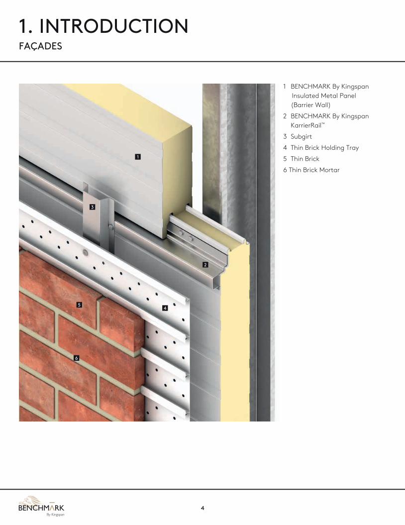
1. INTRODUCTION FAÇADES
1 BENCHMARK By Kingspan Insulated Metal Panel (Barrier Wall)
2 BENCHMARK By Kingspan KarrierRail™
3 Subgirt
4 Thin Brick Holding Tray
5 Thin Brick
6 Thin Brick Mortar
1
2
6
54
3

MARKING THE LOCATION OF THE FIRST STEEL HOLDING TRAYOnce you have determined a starting point, you need to take measurements to assure that the trays are installed level and that trays will align at each corner. The easiest way to determine that the trays are installed level is to measure the distance from your starting point up to the building’s soffit. Repeat this process with each framed opening until all have been measured. Trays that intersect at all corners must align or the thin brick corner units will not fit properly.
MARKING VERTICAL COURSING LINES Thin Brick steel holding trays are 3.20” in height and 5 trays will course every 16” when installed snugly against each other. This is the ideal condition to maintain the optimum joint size and spacing. There will be times when you will spread the trays out slightly in order to adjust coursing to meet certain conditions, such as to meet the top of windows and doors with a full tile to avoid cuts and increase speed of installation.. The trays should never be separated more than 1/8” apart from their fully seated (snuggly fit together) “normal” installed condition.
FINDING AND MARKING WALL STUDS Prior to installing trays, it is helpful to locate and mark the location of wall studs. Marking the stud locations will speed up installation and prevent fasteners from being incorrectly installed in the exterior sheathing.
5
DETERMINING TRAY STARTING POINT One of the advantages of the Thin Brick system is that you can start tray installation at any point on the wall.
The steel holding trays may be installed from the bottom working up a wall or from the top working down the wall.
The key considerations in finding a starting point are:
Finding a low starting point that will allow you to easily keep the trays level .
Determining how close to ground level you want to install trays.
Analyzing all openings and determining a starting point that will minimize course adjustments.
Finding a point that allows for easy chalk line markings.
3.20”
16”
3.20”
3.20”
3.20”
3.20”
6
1. INTRODUCTION FACADES
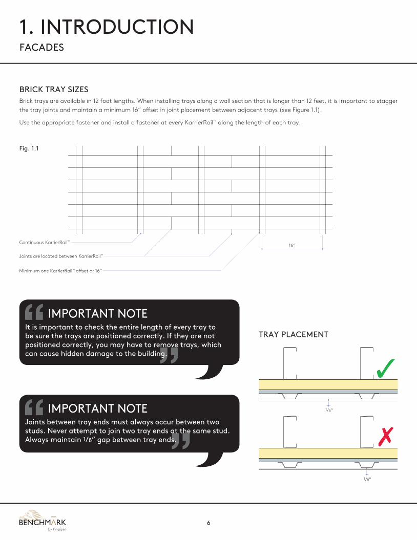
BRICK TRAY SIZESBrick trays are available in 12 foot lengths. When installing trays along a wall section that is longer than 12 feet, it is important to stagger the tray joints and maintain a minimum 16” offset in joint placement between adjacent trays (see Figure 1.1).
Use the appropriate fastener and install a fastener at every KarrierRail™ along the length of each tray.
Continuous KarrierRail™
Joints are located between KarrierRail™
Minimum one KarrierRail™ offset or 16”
16”
Fig. 1.1
IMPORTANT NOTEIt is important to check the entire length of every tray to be sure the trays are positioned correctly. If they are not positioned correctly, you may have to remove trays, which can cause hidden damage to the building.
IMPORTANT NOTEJoints between tray ends must always occur between two studs. Never attempt to join two tray ends at the same stud. Always maintain 1/8” gap between tray ends.
TRAY PLACEMENT
1/8”
1/8”
✓
✗
7
2. INSTALLATIONAT BASE AND CORNER
INSTALLING THE FIRST TRAYAlign your first tray at the proper starting place. Using a screw gun, insert a fastener through the steel holding tray and into the closest stud. Tighten the screw until the screw head is flush with the tray surface. Before inserting another screw, check the alignment of the tray and make sure that it is aligned with the chalk line. Insert another screw through the steel holding tray and into the closest stud at the opposite end of the tray from the starting point. Check the alignment of the tray and finish inserting screws into every stud along the length of the tray.
COMPLETING TRAY INSTALLATION AND JOINT STAGGERING You may install additional trays either moving up or down the wall depending on your starting point. The designed tray spacing is 3.2” which requires the flanges to be firmly seated and the backs of the trays touching each other. However, when you need to spread the trays slightly to meet certain conditions, the trays must never be spaced at more than 1/8” apart per course from their fully seated “normal” install condition. Make certain that every tray flange is firmly seated into the next tray. Use chalk lines and check for level as you install additional trays. Make certain that trays will meet precisely at all corners with the trays on the adjacent wall or corner tile will not work.
PROPER INSTALLATION OF THIN BRICK Each thin brick contains grooves on each long edg pered.
Always install thin bricks with the tapered edge down.
Insert a brick into the tray until the top groove fits into the top tray edge. Using a white rubber mallet, tap the bottom of the brick in an upward motion until the tray bottom edge snaps into the brick’s bottom groove.
STARTING WITH A THIN BRICK CORNER It is recommended to begin brick installation in the two steel holding trays immediately below the lowest window opening.
If you are starting on a wall that requires corner units, begin the brick installation by inserting a corner brick (using the long end) at one end of the wall.
Move to the other end of the wall and insert another corner. Begin filling the first tray completely with thin bricks, allowing 3/8”-1/2” vertical head joints between all bricks, whichever works best for windows, doors and wall length.
TIPWhen installing trays, use the minimum amount of fasteners needed to hold the tray in place until all rails in that section have been placed. This will make adjusting the tray easier if necessary.
8
2. INSTALLATIONAT BASE AND CORNER
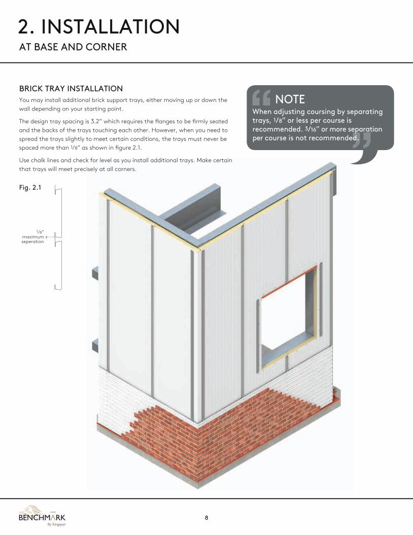
BRICK TRAY INSTALLATIONYou may install additional brick support trays, either moving up or down the wall depending on your starting point.
The design tray spacing is 3.2” which requires the flanges to be firmly seated and the backs of the trays touching each other. However, when you need to spread the trays slightly to meet certain conditions, the trays must never be spaced more than 1/8” as shown in figure 2.1.
Use chalk lines and check for level as you install additional trays. Make certain that trays will meet precisely at all corners.
Fig. 2.1
1/8” maximum seperation
NOTEWhen adjusting coursing by separating trays, 1/8” or less per course is recommended. 3/16” or more separation per course is not recommended.

9
Base at Overhang
Outside Corner
BENCHMARK thin brick
BENCHMARK thin brick
Mortar joint
Continuous KarrierRail™ (KarrierRail™ available in 1”–3” faces)
Expansion fastener as required
Continuous butyl sealant both sides of trim with marriage bead to vertical panel joint
Fastener to concrete (not by Kingspan)
Set KarrierRail™ in butyl sealant at fastener locations
1/4” – 14 hex head fastener with washer
1/4” – 14 hex head fastener with washer
Brick support tray
Base flashing
Continuous butyl sealant
Hat channel set in butyl sealant at fastener locations
Outside corner trim
Inside corner trim
Horizontal support (not by Kingspan)
Continuous butyl sealant
F.I.P. insulation as required (not by Kingspan)
1/4” – 14 hex head fastener with washer
3/4” phil pan head
Pop rivet
Pop rivet
Brick support tray
Mortar joint
Hat channel set in butyl sealant at fastener locations
1/4” – 14 “low profile” fastener with 11/8” bonded washer
Base angle with min. 3” vertical leg for panel attachment set in sealant (not by Kingspan)
BENCHMARK thin brick (bottom course transition option shown)

10
2. INSTALLATIONAT SILL

11
Framed Opening – Sill
Exposed sealant (not by Kingspan) Door / window frame (not by Kingspan)
Sealant
Expansion fastener as required
Miter cut joints where required
Sill trim
Mortar joint
Brick support tray
Continuous KarrierRail™ (KarrierRail™ available in 1”–3” faces)
BENCHMARK thin brick sill
BENCHMARK thin brick
Continuous butyl sealant both sides of trim with marriage bead to vertical panel joint
1/4” – 14 through fastener
1/4” – 14 hex head fastener with washer
WINDOW SILL TREATMENTUsing a BENCHMARK Thin Brick Sill is an easy and attractive method of installing BENCHMARK Thin Brick below windows.
First, cut a piece of thin brick steel tray the same length as the width of the J-channel below the window or the bottom of the window frame (if J-channel was not used).
Second, snap two Tru-Brix S6 sills into each end of the cut tray.
Third, place the tray and sills directly below the bottom of the window frame. Slide the tray up until the top of each S6 sill is snug against the J-channel. If not using J-Channel, trim the top flange of the tray so the tray sits snugly against the bottom of the window frame or sill trim as shown above. Using your screw gun, apply fasteners until the tray is securely fastened. If J-channel was not used, apply a bead of high-quality exterior sealant in the gap between the sill and the window frame.
Finally, remove the two sills and install fasteners at each end of the tray.
Next you must lay out the sills to determine if it is necessary to trim the sill bricks. Each sill measures 7 5/8” in length. After adding 3/8“ for the mortar joint, an installed sill will measure 8“. Re-measure the length of the tray you installed below the window. Divide this measurement by 8“ to determine the quantity of sills required.
It is important to trim the sills so that they are equal in length.
NOTEThe top leg of the tray can be trimmed off to allow a closer fit of sill brick to trim.
Top leg of brick tray
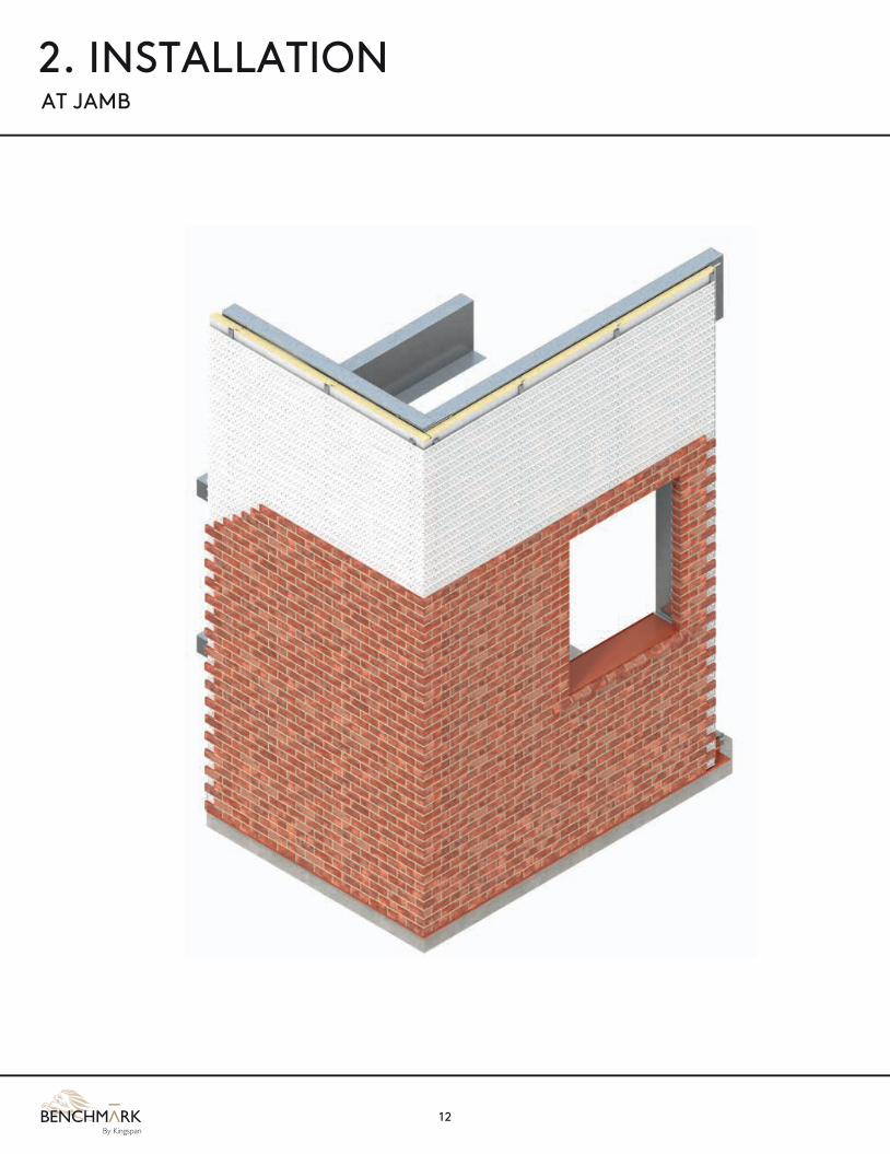
12
2. INSTALLATIONAT JAMB
13
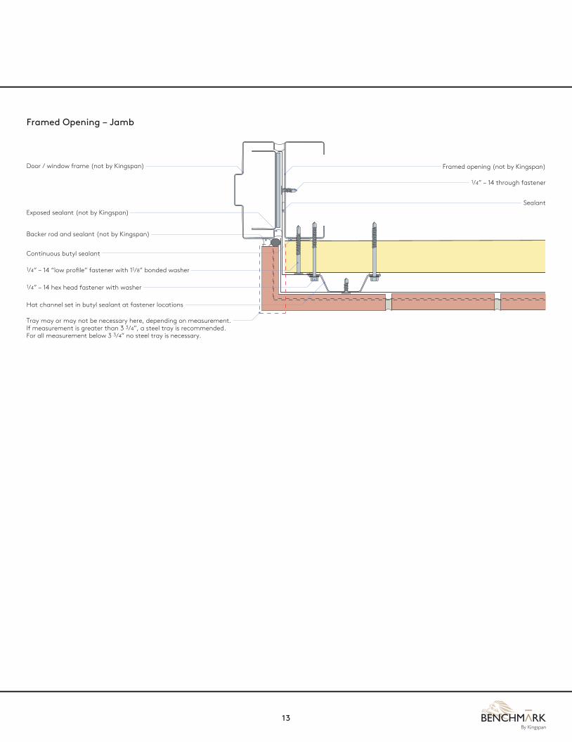
Framed Opening – Jamb
Backer rod and sealant (not by Kingspan)
Exposed sealant (not by Kingspan)
Continuous butyl sealant
Sealant
Door / window frame (not by Kingspan) Framed opening (not by Kingspan)
Hat channel set in butyl sealant at fastener locations
Tray may or may not be necessary here, depending on measurement. If measurement is greater than 3 3/4”, a steel tray is recommended. For all measurement below 3 3/4” no steel tray is necessary.
1/4” – 14 hex head fastener with washer
1/4” – 14 through fastener
1/4” – 14 “low profile” fastener with 11/8” bonded washer

14
2. INSTALLATIONAT HEAD

15
Framed Opening – Head
Exposed sealant (not by Kingspan)
Door / window frame (not by Kingspan)
Framed opening (not by Kingspan)
Expansion fastener as required
Mortar joint
Brick support tray
Drip flashing
Continuous KarrierRail™ (KarrierRail™ available in 1”–3” faces)
BENCHMARK thin brick
Continuous butyl sealant both sides of trim with marriage bead to vertical panel joint
1/4” – 14 hex head fastener with washer

16
MORTAR MIXING INSTRUCTIONS Pour 6 quarts of water into a 5 gallon bucket.
Pour 3/4 of a 50 lb bag of mortar into the bucket with 6 quarts of water.
Mix thoroughly.
Add the remaining dry mortar from the 50 lb bag into the 5 gallon bucket.
Mix again until the right consistency is reached. Do not add more water if seems too dry - keep mixing it will get wetter. If water absolutely needs to be added, do so in very small amounts at a time.
Re-temper (re-mix) every 10-15 minutes or as necessary until mortar is used up. Be sure to only add a little bit of water when re-tempering.
Work in a methodical fashion, 6 - 10 brick across at the bottom course and move up 1 course at time so when it’s time to strike the mortar you begin at the same place you first put the mortar into the wall. Overfill the joint or there won’t be enough mortar to strike. Don’t strike too early or you will have a messy smeared wall. The mortar needs to setup to the point that it strikes well and the excess falls right off.
3. MORTAR
PRE-MORTARING CHECKLIST Inspect all wall areas for any defects prior to starting the grouting process. Remove and replace any off color or broken bricks before grouting. Read and follow instructions.
Mortar is available in 50lb bags which will cover approximately 27 square feet for modular bricks and approximately 32 square feet when used in conjunction with modular oversized bricks.
CAUTIONBe careful not to add too much water, which will make the mortar too thin. Soupy mortar may slump during application resulting in walls that will require cleaning after grouting.
CAUTIONUseful life of mixed mortar is only 30 to 40 minutes. If you cannot use the entire batch in the alloted time, mix half batches of mortar.

17
PREPARING THE MORTAR POINTING GUN Once assembled, lightly spray WD40 or a similar lubricant into the gun’s tube. Also lightly coat the rubber gasket attached to the gun’s plunger.
Using the scooper, fill the pointing gun cartridge completely with mortar.
Begin filling the joints by starting with the vertical head joints. Work carefully to prevent excess mortar from dripping on the brick faces.
After two rows of vertical head joints, begin filling the adjacent horizontal bed joints.
CAUTIONMake sure that all head joints are completely filled. If some joints are not completely filled, take mortar from a joint that has been overfilled. Simply scrape the excess off with the striking tool and apply the mortar to the joint that is underfilled.
HINTIf you spill mortar on to the faces of the bricks , wait until striking is completed before trying to remove the mortar droppings. If you immediately try to remove the droppings, the mortar will smear and cleaning may be required when finished grouting.

18
4. CONSTRUCTION DETAILS
Stack Joint
Parapet
Fastener as required (not by Kingspan)
Membrane roof and parapet backer (not by Kingspan)
Horizontal supports (not by Kingspan)
Fastener to parapet backer (not by Kingspan)
Expansion fastener as required
Expansion fastener as required
Wrap membrane over brick (not by Kingspan)
Parapet assembly Parapet blocking (not by Kingspan)
Mortar joint
Mortar joint
Brick support tray
Brick support tray
Continuous KarrierRail™ (KarrierRail™ available in 1”–3” faces)
BENCHMARK thin brick
BENCHMARK thin brick
Continuous butyl sealant with marriage bead to vertical panel joint
Continuous butyl sealant both sides of trim with marriage bead to vertical panel joint
1/4” – 14 hex head fastener with washer
1/4” – 14 hex head fastener with washer
F.I.P. insulation as required (not by Kingspan)

19
Low Eave
Rake
Refer to 900/1000 Series roof panel details for additional information
Refer to 900/1000 Series roof panel details for additional information
Rake angle (not by Kingspan)
Eave strut (not by Kingspan)
Expansion fastener as required
Expansion fastener as required
Mortar joint
Mortar joint
Brick support tray
Brick support tray
BENCHMARK thin brick
BENCHMARK thin brick
Continuous butyl sealant both sides of trim with marriage bead to vertical panel joint
Continuous butyl sealant both sides of trim with marriage bead to vertical panel joint
1/4” – 14 hex head fastener with washer
1/4” – 14 hex head fastener with washer
F.I.P. insulation as required (not by Kingspan)
F.I.P. insulation as required (not by Kingspan)
Continuous KarrierRail™ (KarrierRail™ available in 1”–3” faces)
NOTERake should fasten through the mortar joint. Fastener holes should be pre-drilled. Do not fasten through the brick as bricks will crack.
20
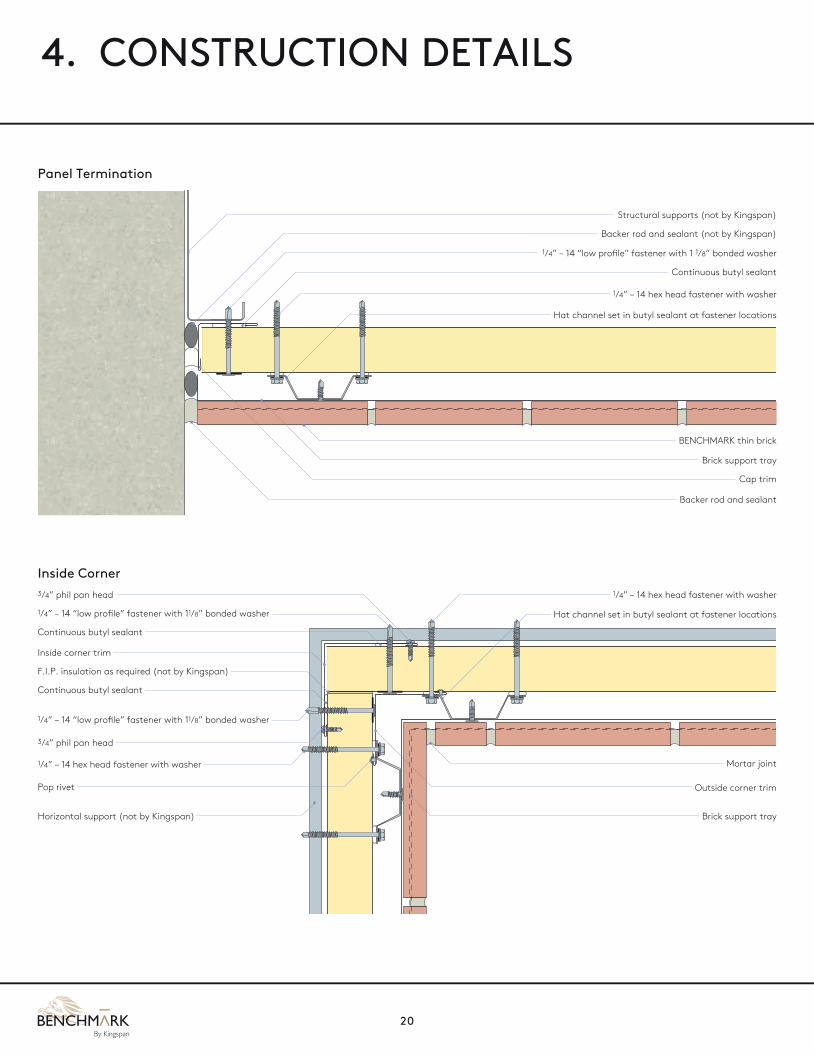
Panel Termination
Structural supports (not by Kingspan)
Backer rod and sealant (not by Kingspan)
Continuous butyl sealant
Hat channel set in butyl sealant at fastener locations
1/4” – 14 hex head fastener with washer
1/4” – 14 “low profile” fastener with 1 1/8” bonded washer
Backer rod and sealant
Cap trim
Brick support tray
BENCHMARK thin brick
Inside Corner3/4” phil pan head
3/4” phil pan head
Hat channel set in butyl sealant at fastener locations
Outside corner trim
Mortar joint
Inside corner trim
Horizontal support (not by Kingspan)
Continuous butyl sealant
Continuous butyl sealant
F.I.P. insulation as required (not by Kingspan)
1/4” – 14 hex head fastener with washer
1/4” – 14 hex head fastener with washer
Pop rivet
Brick support tray
1/4” – 14 “low profile” fastener with 11/8” bonded washer
1/4” – 14 “low profile” fastener with 11/8” bonded washer
4. CONSTRUCTION DETAILS

21
Horizontal Expansion Joint
Vertical Expansion Joint
Brick support tray with #8 x 3/4” modified truss head #2 phillips drive self-drilling fasteners at each tray (24” O.C.)
3/4” horizontal expansion joint
Sealant along horizontal expansion joint
Flat trim
Girt (not by Kingspan)
Backer rod
Field cut KarrierRail™
Brick adhesive between brick tray and brick
2 x #14 HH fasteners with bonded washers
BENCHMARK thin brick
Vertical KarrierPanel
Sealant on both sides
Mortar joint
Continuous KarrierRail™ (KarrierRail™ available in 1”–3” faces)
#14 HH thru fastener with bonded washer at each steel support
Brick support tray with #8 x 3/4” modified truss head #2 phillips drive self-drilling fasteners at hat-bar
Vertical wall panel
16GA. hat-bar
Backer rod
3/4” horizontal expansion joint
Steel Support (not by Kingspan)
Sealant
Flat trim
Mortar joint
BENCHMARK thin brick
Sealant along vertical expansion joint
3/4”
3/4”
21/4”

22
5. MATERIALS TOOLS AND HARDWARE
TOOLS AND SEALANTS
Electric tin snips
Brick Guillotine (Chopper)
Pointing Gun
Metal cutting circular saw with fine tooth carbide blade
Tape measure
Mortar paddle
Power drill / Screw gun
Chalk line
Mortar scoop
Caulking gun
Grout bag
Rubber mallet
Mason’s Soft Bristle Brush

23
NOTES

BENCHMARK SupportBENCHMARK By Kingspan Columbus, OH, USA 1-888-332-5862Modesto, CA, USA 1-800-377-5110Caledon, ON, CA 1-866-442-3594www.BENCHMARKbyKingspan.us www.BENCHMARKbyKingspan.ca
Care has been taken to ensure that the contents of this publication are
accurate, but Kingspan Limited and its subsidiary companies do
not accept responsibility for errors or for information that is found
to be misleading. Suggestions for, or description of, the end use or
application of products or methods of working are for information
only and Kingspan Limited and its subsidiaries accept no liability in
respect thereof.