Embed Size (px)
Citation preview

ECE 211 Workshop: Thevenin’s and Norton’s Theorems
Academic Resource Center

Agenda
• Background: Thevenin’s Theorems Review
• Thevenin's Analysis o How to find Equivalent Thevenin's Voltage
Source and relating problems
o How to find Equivalent Thevenin's Resistor and relating problems
• Transformation between two Theorems • Practice Problems and Solutions

Thevenin's Theorem Review
General Idea: In circuit theory, Thévenin's theorem for linear electrical networks states that any combination of voltage sources, current sources, and resistors with two terminals is electrically equivalent to a single voltage source V in series with a single series resistor R. Those sources mentioned above can be either independent or dependent.

Thevenin's Theorem Review
Analyze Procedure: 1.Calculate the output voltage, V, when in open circuit condition (no load resistor—meaning infinite resistance). This is VTh. 2.Calculate the output current, IAB, when the output terminals are short circuited (load resistance is 0). RTh equals VTh divided by this IAB. Step 2 could also be thought of as: 2a. Replace voltage sources with short circuits(wires), and current sources with open circuits(disconnections). 2b. Calculate the resistance between terminals A and B. This is RTh.

Thevenin's Voltage Example
• Find equivalent voltage source in new circuit
• Solution: Between terminals A and B, we need to find out V. Since it's open circuit and there is no current going through R1.Treat
R1 as wire. ciucuit become
simple three series resistor and a voltage source. Secondly, find the current. Thirdly, find the sum voltage across R3 and R2. That's the answer we're looking for.
Using Ohm’s law, we find: I = V/R, where V = 15V
R = R4+R3+R2 = 4Ohm I = 15/4 = 3.75A Ohm's law again, Vab = 2*3.75 = 7.5V

Practice Problems 1A

Practice Problems 1B
There is only one path in the circuit, so
the ratio of the two resistors are the
ratio of their voltages(same current).
V0 + 2V0(20K Ohms) +4V0 = 70V
V0 = 10V
Two ways finding Vab:
Vab = 70V- V0
=2V0 + 4V0
= 60V

Practice Problems 2A

Practice Problems 2B
Firstly, if we perform the source
transformation, the original circuit
changes to a simple series one. Notice
the two source are in the opposite
direction.
Vsigma = 60V - 30V = 30V
Rsigma = 30 Ohm + 60 Ohm= 90 Ohm
Isigma = Vsimga/Rsigma = 1/3 A
V12 = V60 +30V
= 1/3 * 60 + 30V = 50V

Thevenin's Resistor Example A
• Find equivalent resistor in new circuit
• Solution: Original method: short terminals A and B as shown in the picture. Find the current I going through A to B. Rth can be found by V/I,where V is the voltage we get from last problem.
R2,3 = R2+ R3 = 2 Ohm
R2,3,1 = R2,3 || R1 = 2/3 ohm
Rsigma = R1,2,3,4= R2,3,1 + R4 = 8/3 ohm
Isigma = V1/Rsigma = 45/8 A
IAB = Isigma * (R2+R3) / (R1+R2+R3) = 15/4 A
Rth = VAB/IAB = 2 Ohm
Thevenin's Resistor Example B
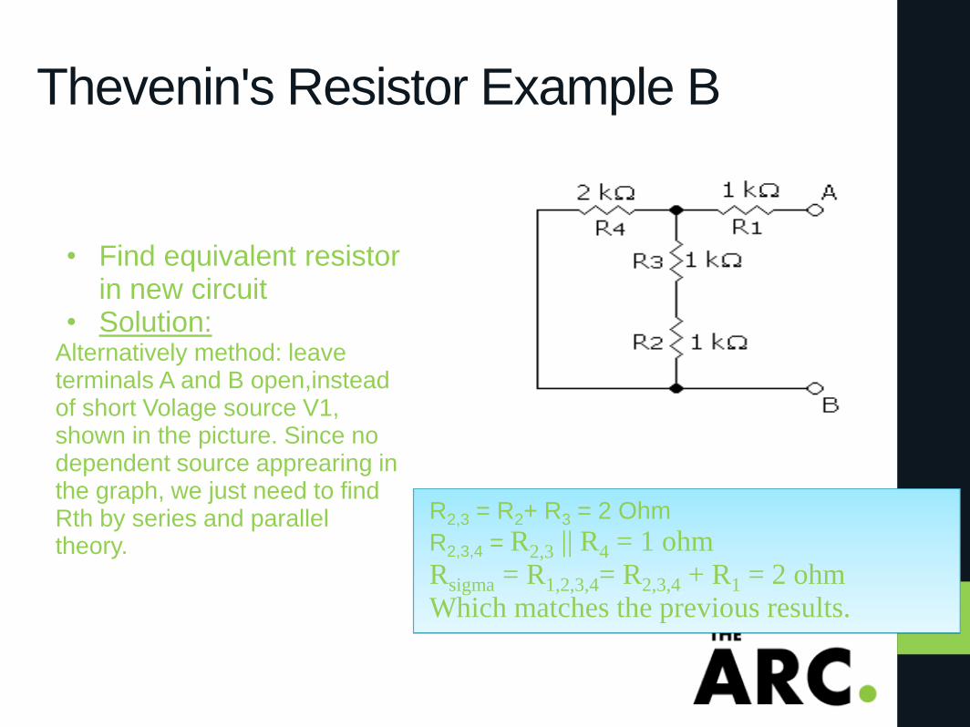
• Find equivalent resistor in new circuit
• Solution: Alternatively method: leave terminals A and B open,instead of short Volage source V1, shown in the picture. Since no dependent source apprearing in the graph, we just need to find Rth by series and parallel theory.
R2,3 = R2+ R3 = 2 Ohm
R2,3,4 = R2,3 || R4 = 1 ohm
Rsigma = R1,2,3,4= R2,3,4 + R1 = 2 ohm
Which matches the previous results.

Thevenin's Example summary
1 The graph shown in the right
hand side gives the final result
for Thevenin's theory.
compared with original circuit,
it looks a lot easier to further
analyze.
2 Generally speaking, out of the
two ways in findng equivalent
resistor. A is more suitable for
graph containing denpendent
source. B is more useful in the
situation of simply parallel
and series resistors.

Practice Problems 3A

Practice Problems 3B
When we try to calculate the quivalent
resistor, simply short indenpendet
voltage source and open independent
current source. Then, the lower left
circuit is derived.
R1 = 16 Ohm + 4 Ohm = 20 Ohm
R2 = R1 || 5 Ohm = 20 Ohm || 5 Ohm
= 4 Ohm
Rsigma = R2 + 1 Ohm = 5 Ohm

Practice Problems 4A
Practice Problems 4B
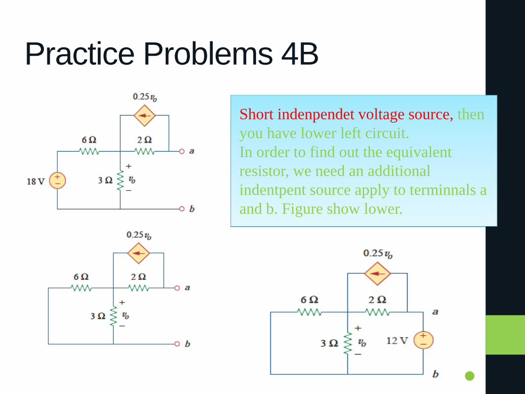
Short indenpendet voltage source, then
you have lower left circuit.
In order to find out the equivalent
resistor, we need an additional
indentpent source apply to terminnals a
and b. Figure show lower.

Practice Problems 4B
Assumption: current direction in 2
Ohm is a to N. 6 Ohm and 3 Ohm
share the same voltage(V0). For node
N, current going out are (V0/6 + V0/3).
Assumption: current direction in 2
Ohm is a to N. Total current going in:
(0.25v0 + i). From KCL we equal (V0/6
+ V0/3) with (0.25v0 + i), we get i =
v0/4.
From KVL v0/4 * 2 + v0 = 12 V
v0 = 8 V
Iab = 0.25v0 + v0/4(2 Ohm) = 0.5 v0 =
4A
Rth = Vab/Iab = 12/4 = 3 Ohm
Since we assume the voltage
source has a value of 12V, we need
one more parameter, current
I(through voltage source) to figure
out resistance using equation R=
U/I.

Norton's Theorem Review
General Idea: Norton's theorem for linear electrical networks, known in Europe as the Mayer–Norton theorem, states that any collection of voltage sources, current sources, and resistors with two terminals is electrically equivalent to an ideal current source, I, in parallel with a single resistor, R. Those sources mentioned above can also either be dependent or independent sources. Analyze Procedure: 1.Find the Norton current INo. Calculate the output current, IAB, with a short circuit as the load (meaning 0 resistance between A and B). This is INo. 2.Find the Norton resistance RNo. There are two methods of determining the Norton impedance RNo. (the same as Thevenin's Theorem)

Transformation between two methods
From the description we have seen at least two simiarities. Firstly, they both use load equaling to 0 finding current. Secondly, the way they finds quivalent resistors are precisely matched. Thus we conclude that those two are essentially the same.
Transformation eqation are:
Rno = Rth
Vth = Ino * Rno
Ino = Vth / Rno

Practice Problems

Practice Problems

Solutions to Practice Problems Vth: (original figure)
1k * I0 + 2 Vx = 3V
Vx = 40I0 * 50
solve the above:
Vx = Vth = 1.2V
I0 = 0.6 mA
We short the votage source and
add an additional votage source
between a and b.(lower figure)
Rth:
So, we have: 1000 * I0 = -2*Vx
Vx = 3V
solve the above:
I0 = -6 mA
-40 I0 - Vx/50 = Iab = 0.18A
direction: a to b
Rth = 3V/ Iab = -16.67 Ohm

Solutions to Practice Problems Vth:
(2i + 0.5 Vx) *10 +2i = Vx
(Vx/6 + i) * 3 + Vx = 50
solve the above:
Vx = 100V,i = -33.3A
Vth = (0.5 Vx + i ) = 166.67 V
We short the votage source and
add an additional votage source
between a and b.
Rth:
So, we have:
Vx/6 +Vx/3+ i = 0
Vx - 2i = 50V
solve the above:
i = -12.5A, Vx = 25V
Iab= -i - 0.5Vx + 50V/10 = 5A
direction: b to a
Rth = 50V/ Iab = 10 Ohm

• END!!