Embed Size (px)
Citation preview

Santiago de Queretaro, Qro., Mexico, February 2017
RAPID programming of an assembly cell of LEGO carsand modelling the system using SysML
ThesisTO ACHIEVE THE ACADEMIC DEGREE OF
Master in Mechatronics
BY
Israel Alvarez Mendoza

Declaration
I declare that this thesis was composed by myself, that the work presented here is my own except
where explicitly stated otherwise in the text, and that this work has not been submitted for any
other degree or professional qualification except as specified.
Israel Alvarez Mendoza
i

Acknowledgements
There are some people and instances I’d like to thank for helping me in the accomplishment of
this thesis.
First I’d like to thank CIDESI for gave me the opportunity of make this master degree. Special
thanks to Mtro. Salvador Pérez Arce, Bertha Elisa Velasco Sanchez, Roberto Sosa Cruz and
Leonardo Aurelio Baldenegro Pérez, for their support and will to help me.
I also like to thank FH Aachen, for being a great host university for me as a student. Special
thanks to Prof. Jörg Wollert for gave me the opportunity of working in this fascinating project
and for always believe in me. I appreciated the help of Sebastian Rau, Marc Gröniger, Florian
König, and everyone working in the lab, amazing and very patient people.
My biggest appreciation to CONACyT for funding my education in Mexico and in Germany,
without it, this project wouldn’t have happened.
I feel gratitude to my colleagues of thesis Rodrigo Torres Arrazate, Alfonso Castro Medina,
Victor Antonio Saldivar Moreno, and Alexander Dahm, for being a great team of work through
thick and thin.
Last but not least, I want to thank my parents, Gabriel Alvarez Arellano and Ana María Mendoza
Londoño, and my sister, Carolina Alvarez Mendoza for always being there for me supporting,
every decision I made, giving me advices and helping to believe in me.
ii

Abstract
In the industries exist a vast variety of robot cell dedicated to one or multiple assignments from
soldering to painting, packaging, as well as assembling. Each day industrial robots are reaching
new markets, and with this, the necessity to have an easy to use and yet powerful programming
language is bigger than ever. RAPID is a high level programming language developed by ABB
for robots of the same manufacturer. This language is incorporated in the software RobotStudio,
developed by the same company for programming, debugging and simulating of robot cells.
Using this tool I am going to program a ABB Flexpicker IRB 340 that is used for assembling cars
made with Lego blocks, taking advantage of the best attribute of delta robots; Pick&Place.
A general SysML model is presented to show the general interface of the main parts in the cell.
iii

Content
Declaration...................................................................................................................................i
Acknowledgements....................................................................................................................ii
Abstract.....................................................................................................................................iii
Chapter 1: Introduction...............................................................................................................1
1.1 Problem Statement....................................................................................................2
1.2 Objectives.................................................................................................................3
1.3 Justification...............................................................................................................4
Chapter 2: Background...............................................................................................................5
2.1 Industrial robots........................................................................................................5
2.2 Delta robots...............................................................................................................7
2.3 SysML......................................................................................................................9
Chapter 3: Main components of the assembly cell...................................................................11
3.1 Hardware.................................................................................................................11
3.1.1 IRB 340....................................................................................................11
3.1.2 IRC 5 controller.......................................................................................13
3.1.3 Flexpendant..............................................................................................15
3.2 Software..................................................................................................................16
3.2.1 RAPID language......................................................................................16
3.2.2 RobotStudio.............................................................................................18
Chapter 4: Methodology...........................................................................................................19
Chapter 5 SysML......................................................................................................................21
Chapter 6: Procedures prior to program the robot....................................................................25
6.1 Backup controller....................................................................................................26
6.2 Backup parameters..................................................................................................27
iv

6.3 Upgrade RobotWare...............................................................................................28
6.4 Copy of Real controller..........................................................................................29
6.5 Calibrating IRB 340................................................................................................30
6.6 Jogging the robot....................................................................................................32
Chapter 7: Programming in RAPID.........................................................................................33
7.1 Create Robot cell using RobotStudio.....................................................................33
7.2 Create tool...............................................................................................................34
7.3 Create targets and Path and routines.......................................................................35
7.3.1 Targets......................................................................................................35
7.3.2 Path..........................................................................................................35
7.3.3 Routines...................................................................................................36
7.4 RAPID program......................................................................................................37
7.4.1 Definition of constants, variables, and targets.........................................37
7.4.2 Definition of routines...............................................................................39
7.4.3 Main Procedure........................................................................................41
Chapter 8: Simulation and test in real robot.............................................................................44
8.1 Simulation test........................................................................................................44
8.2 Real robot test.........................................................................................................45
8.3 Conclusions............................................................................................................47
References.................................................................................................................................48
Index of figures.........................................................................................................................49
Appendix A RAPID program...................................................................................................50
v

Chapter 1: Introduction
In this project I am going to program a delta robot IRB 340 Flexpicker from ABB using RAPID
language for the main purpose of assemble cars builded with Lego blocks. This thesis is divided
in eight chapters. Chapter one is about the definition of problem statement, general and particular
objectives and the justification of the project. Chapter two takes the reader into the background
of industrial robots, their applications in the industry, a brief history of delta robots and the basics
of SysML. Chapter three deals with the defining the main components of the assembly cell. In
chapter four is the methodology of the project. Chapter five shows the SysML model designed
for the assembly cell with a description of the blocks and connections used. Chapter six mentions
the steps followed prior to the programming of the robot. Chapter seven describes the process of
programming a robot cell using RAPID language in RobotStudio. Finally chapter eight explains
the results presented in the virtual and real environment as well as the conclusions. The final
program is located in Appendix A.
1

1.1 Problem Statement
Every year more industries are shifting their repetitive manual labours into a more efficient and
productive way of producing goods for the end consumer with the help of industrial robots.
Nowadays one can find this type of machinery in a variety of manufacturing industries, like in
the fabrication of electronics for consumers, the packaging of food, sorting pharmaceutical
material, etc.
Using delta robots in the assembly of a car made with Lego bricks is a challenging task because
of the need of an extreme precision in the picking and placing of every block to its final
destination, and to verify that each piece is joined with each other correctly.
The system used for this study is as follows: A delta robot from ABB, model IRB 340 Flexpicker
with an end effector specially designed to easily grab the Lego blocks, a IRC5 controller from
ABB for the control of the servomotors of the robot, a conveyor feeding the assembly cell with
Lego blocks and a workspace for the process of mounting every piece in place. Additionally to
that I am using a PC with the software RobotStudio to make the simulation and offline
programming in RAPID language of the robot. At the end of the project assembly cell is going to
be modelled in a general manner using the modelling language SysML.
With the implementation of the IRB 340 to the assembly of Lego cars I would like to see if this
type of industrial robot is not only useful for sorting and packing of material, but also in the
assembly of certain parts that its construction is sort of modular, in that case the pick and place
technique fits adequately.
2

1.2 Objectives
General Objective:
• Program a IRB 340 Flexpicker robot using the standard programming language from
ABB, RAPID, to pick and place different types of Lego blocks in order to assembly three
different models of toy cars and model the fundamental assembly cell components with
the modelling language SysML.
Particular Objectives:
• Identify the main components of the assembly cell.
• Identify the interrelation of the main components with each other.
• Create backup of the previous system.
• Calibrate the robot manipulator.
• Create a copy of the real controller.
• Define the input and outputs in the IRC5 controller parameters configuration.
• Create a station in RobotStudio.
• Create a tool in RobotStudio.
• Define the targets to be used for picking and placing the different blocks and chassis.
• Check the correct orientation of each target.
• Create the main routine in RAPID.
• Develop routines for picking blocks and chassis using RAPID language.
• Develop routines for placing blocks and chassis using RAPID language.
• Define the variables used in the program.
• Simulate the assembly pick and place of Lego blocks and chassis in RobotStudio.
• Load the program to the real controller.
• Test of RAPID program in real controller.
• Model the main component and their interfaces with the SysML standard language.
3

1.3 Justification
The purpose of this investigation is to use a IRB 340 robot, which is a delta industrial robot to
assembly toy cars in a modular way, in this case handling Lego bricks taking advantage of the
most common use of this kind of robots, pick and place. At the same time we try to verify how
fast is it possible to build one of these cars in a safe way for the assembly cell and for the
assembled car.
The development of this project is going to be useful to show the potential of this industrial robot
and how this can be suitable for assembly tasks. Equivalently this project is going to be used for
demonstrations in trade fairs in order to demonstrate how versatile and adaptable it can be.
4

Chapter 2: Background
2.1 Industrial robots
Since the beginning of the Industrial revolution mankind has searched to replace tedious,
repetitive labours of human workers with special machinery capable of automate the processes
and at the same time make it faster, cheaper and guarantee repeatability and standards in every
produced goods. In 1769 with the invention of the steam machine created by James Watt marked
the beginning of the industrial automation. Henry Ford took advantage of the automation of
industrial processes in 1908 to help him with the mass production of the Model T and in 1923
Morris Motors in the UK employed the automatic transfer machine. Although these are examples
of the automation of processes in the industry it could be considered like a mechanization of
processes. It is until 1950’s when the first programmable devices started to appear, with the
development of the numerically controlled machine tool developed by MIT. In 1961 General
Motors installed the first industrial robot, and in 1969 the first programmable logic controller[1].
Henceforth the industry realised that the use of industrial robots for manufacturing processes is
beneficial for the companies, as well for the customers. To make clear what is an industrial robot,
I’d like to make use of the definition by the International Federation of Robotics in ISO 8373 [2]:
An automatically controlled, reprogrammable, multipurpose manipulator programmable in three
or more axes, which may be either fixed in place or mobile for use in industrial automation
applications.
5
Many different types of industrial robots emerged and with it a variety of industries began to
implement this machinery in their manufacturing plants. In 1956 Joseph Engelberger and George
Devol established Unimation, and with this came the first industrial robot, the Unimate, who was
used for the stacking of die cast parts at the General Motors plant in Trenton, New Jersey. In
1969 Unimation used robots for spot welding in the assembly plant of Lordstown for General
Motors. This helped to enabled the automation of more than 90% of its spot welds. In 1979 the
first six electromechanically driven axes robots were developed by KUKA in Germany.
Kawasaki produced the first robot with a mini computer-based controller, the Cincinnati
Milacron T3 in 1974. In the same year ASEA in Sweden released the first fully electric
microprocessor-controlled robot, the IRB 6, an arm like machine capable of carrying 6 kg. The
programmable universal machine for assembly (PUMA) and the first selective compliance
assembly robot arm (SCARA) were developed by the year of 1978, for the purpose of
assembling, with the drawback of the lifting capacity but improving repeatability and speed. In
1984 the first direct-drive SCARA robots were produced. This meant that the gears, chains or
belts for driving the force of the motor to the arm were discarded in favour of a more direct
connection, in order to improve accuracy and reliability.
By the year of 1992 the first delta robot was put in operation, and later on ABB adopted this
technology for making the Flexpicker robot, that by the time was the fastest picking robot [1].
In 2003 there were 800,000 robots in operation, and recently in 2012 there were over one million
industrial robots in operation with half of them used in the automotive industry. Nowadays the
number of operational industrial robots it's around 1.7 million of units and it's expected to
overpass 2.5 millions by the end of 2019 [3].
6

2.2 Delta robots
Prior to the definition of a delta robot we have to define the upper category at which delta robots
belong to; parallel robots. According to J. -P. Merlet, the following definition describes those
type of robots:
A parallel robot is made up of an end-effector with n degrees of freedom, and of a fixed base,
linked together by at least two independent kinematic chains. Actuation takes place through n
simple actuators [4].
Delta robots are the most popular application of parallel robots. They consist of three
parallelograms, each one attached to a servomotor that is located at the base of the robot. The
other end of the parallelograms are connected to the end effector. Finally there is a fourth leg
mounted in the middle of the robot used to rotate the end effector.
Fig. 1 Schematic of delta robot (US patent No. 4,976,582)[5]
7

We can consider the painting robot patented by Willard L. V. Pollard Jr. as the ancestor of the
delta robot, but it was Reymond Clavel the one who developed the first delta robot and
considered the most famous of the parallel robots in the early 80’s [4]. Many companies
fabricated delta robots afterwards including Demaurex, Elektra, Hitachi, and ABB. The latter
brought to market the delta robot IRB 340 Flexpicker in 1999. This robot was thought to be
introduce in industries like the food industry, pharmaceutical and electronics [5].
8
2.3 SysML
To fully understand what is the SysML we need first to talk about another modelling language,
Unified Modelling Language (UML). UML is a rich language for modelling both software and
systems, and is the de facto standard for software modelling [6]. UML has four basic diagrams;
behavioural diagrams, structure diagrams, interaction diagrams and functional diagrams. From
them derive more secondary diagrams. One of the advantages of working with UML for
modelling is that is very easy to learn, intuitive to use, and has well defined structures.
In many cases one can use UML to describe a complete system, but sometimes is not enough,
because UML is more convenient for software engineering [7]. For this reason SysML (Systems
Modelling Language) arises as a complementation of the well established Unified Modelling
Language. SysML is a general-purpose graphical modelling language that supports the analysis,
specification, design, verification, and validation of complex systems. These systems may
include hardware and equipment, software, data, personnel, procedures, facilities, and other
elements of human- made and natural systems [8].
It is based on UML but also has some unique diagrams such as the requirements diagram. UML
profiles can be employed to restrict or extend SysML features to serve a specific domain, as for
example real-time and embedded systems [9].
With the creation of systems that get more complex every year the understanding of them was
becoming more difficult. For this reason SysML emerged as a way for engineers to get the
abstraction of complex systems. This helps in the development of functional, easier to understand
and later on the process of modify or upgrade the whole system is more simple and efficient.
9
There are some previous works of people who has implemented SysML to some robotics
applications. To cite some examples we have the implementation of SysML to the modelling of
complex space robotic systems used in satellite servicing missions. They argue that SysML is a
good option because of the automated requirement verification and model tracing that is possible
with SysML, which can be used to reduce cost and time in the system engineering. Another case
for using SysML in the design of mobile robots. In this work the software for a mobile robot is
developed using the model-based system engineering (MBSE) approach. The claim is that using
MBSE (with SysML as the specific implementation) can enable the creation of reusable software
modules for programming the robot to allow platform independent design and reduced
development time [10].
Using SysML for the modelling of the system simplifies the process of programming. In some
cases is even possible to translate a SysML model to a programming structure like XML [9].
10

Chapter 3: Main components of the assembly cell
3.1 Hardware
3.1.1 IRB 340
Fig. 2 IRB 340 Flexpicker [11].
The delta robot developed by ABB, IRB 340 Flexpicker was the first commercial delta robot of
the company, delivered in 1999. It is a very reliable and flexible machine capable of accomplish
150 picks per minute. It is used in tasks that require to move pieces very quickly but, at the same
time, with great precision, from one location to the other. One of the main advantages of this
robot is that there is a wash down version, which is very useful for places where a strict hygiene
is needed, like when the robot handles food or pharmaceutical products, even some electronic
part demand a clean environment [11].
11

Some of the main features are listed here.
• Three versions: standard, wash-down and stainless wash-down.
• For each version there is a variant for 1 Kg and 2 Kg handling load.
• 4 axis in total.
• Maximum speed: 10 m/s
• Maximum acceleration; 100 m/s2 for 1 Kg load, 60 m/s2 for 2 Kg load.
• Conveyor tracking.
• Supply Voltage: 200 - 600 V, 50 / 60 Hz.
• Degree of protection: standard, IP55; wash-down and stainless wash-down, IP67.
Fig. 3 Working range IRB 340 (in mm) [11].
12

3.1.2 IRC 5 controller
Fig. 4 IRC5 controller from ABB [12].
The latest and most versatile ABB controller to date is the IRC 5. For this model ABB
incorporate some useful features, like a modular shape, which makes possible to stack one
controller over another for space convenience. Another remodelled component in this controller
is the portable interface unit, flexpendant, that incorporates a friendly, windows based, touch
screen interface. One key element of this controller is the capacity of controlling multiple robots,
but at the same time keeping a minimum dependency between each one of them. All ABB robot
controllers are programmed with RAPID high level programming language.
The controller used in this project is a IRC5 single cabinet. It contains the required electronics to
control the manipulator, additional axes and peripherals. The controller is divided in two
modules: drive module, which contains the drive system, and the control module; this one
contains the main computer, the main switch, communication interfaces, flexpendant connection,
service ports and some space for customer peripherals like I/O Boards [13].
13

The main aspects of the IRC 5 are listed in the following.
• Multiprocessor system, pentium CPU.
• PCI Bus
• Flash disk
• USB interface
• Ethernet interface
• Energy backup
• High-level RAPID robot programming language
• PC-DOS file format
• RobotWare software products
• Flexpendant interface
14

3.1.3 Flexpendant
Also called teach pendant unit, or TPU, it is main interface for the operator to control basic
actions like jogging the robot, producing editing and running programs and also visualise, and
monitoring the inputs and outputs. It incorporate a clean, easy to use touch screen windows based
interface, for easiness of displaying and selective main functions of the robots. In addition to it, it
has a 3D joystick for jogging the robot, buttons, some of them customisable and an enabling
device button [14].
Fig. 5 Teach pendant hardware layout [14]
15

3.2 Software
3.2.1 RAPID language
RAPID is a high-level programming language developed by ABB for the programming of robot
controllers and manipulators of the same brand. It is very flexible and easy to use language but,
at the same time, it’s a powerful tool for programming robots for applications like welding and
assembly [12]. Some of the main aspects of this language are listed below [13]:
• Hierarchical and modular program structure to support structured programming and reuse
• Routines can be Functions or Procedures
• Local or global data and routines
• Data typing, including structured and array data types
• User defined names on variables, routines and I/O
• Extensive program flow control
• Arithmetic and logical expressions
• Interrupt handling
• Error handling
• User defined instructions (appear as an inherent part of the system)
• Backward handler (user definition of how a procedure should behave when stepping
backwards)
• Many powerful built-in functions, for example mathematics and robot specific
• Unlimited language (no max. number of variables etc., only memory limited). Built-in
RAPID support in user interfaces, for example user defined pick lists, facilitate working
with RAPID
16

To have a better understanding of the terminology used for RAPID programs I’d like bring some
definitions for the most common terms mentioned in RobotStudio manual[15].
Data declaration: Used for creating data types, variables and instances, e.g. tooldata, num, string.
Instruction: A piece of code that makes something happened like setting data.
Move instructions: It creates the motion of the robot, consist in a reference to a target and the
motion parameters, e.g. MoveL.
Routine: It is a set of declarations followed by a set of instructions that implements a specific
task. Can be procedures, functions or traps.
Procedure: Set of instructions without returning a value.
Function: Set of instructions returning a value.
Traps: Set of instructions triggered by interrupts.
Module: It is a set of declarations and routines. These are splitted into program and system
modules.
Program module (.mod): user made routines.
System module (.sys): contains system specific routines.
Program file (.pgf): a RAPID program consist of a collection of module files (.mod)
and the program file (.pgf.) that references all the module files.
17

3.2.2 RobotStudio
Another important actor in the play of programming ABB robots it’s RobotStudio. It is a versatile
software developed by ABB for modelling, simulating and offline programming of robots cells.
The use of RobotStudio combined with the Flexpendant consist the fundamental tools for
programming almost any ABB robot cell. This software can be used in two modes; online and
offline. The online mode is referred to when a PC running this software is connected through the
Ethernet port of the IRC5 controller, therefore every modification in the simulation can be
transferred to the real controller. Offline mode is used when there is no access to the real
controller, hence it is connected to a virtual controller (VC). One of the advantages of using this
software is that the robot operator can be programming the manipulator in offline mode and after
testing the results in a virtual environment and checking that there are no errors, then it’s safe to
transfer the program to the real controller [15].
18

Chapter 4: Methodology
The fundamental steps to set up the assembly cell consist of:
First we need to connect the Flexpicker and the Flexpendant to the IRC5 controller (power and
data cables). Once everything is connected we will connect the IRC5 to the power grid. After that
we are going to assure that the operation mode of the controller is in Manual 25%, and then turn
it on. If everything is working correctly the flexpendant should start and display no major errors.
The next step is to calibrate the robot with the Flexpendant and adjusting the robot arms with aid
of the calibration mark. With the manipulator already calibrated, we proceed to connect a PC
with RobotStudio software and make a copy of the real controller. Completing this steps we start
to work on the program, starting with the creation of the assembly cell in RobotStudio. Then we
define in which coordinate frame is going to define the movements of the manipulator. Thereafter
we define the tool to used as end effector. Afterwards we start to create the targets for every
position the manipulator is going to reach. Once the targets are created is possible to create the
main path for defining the route the robot is going to follow and synchronize it to RAPID
language. Following with this we are going to create the program logic for pick and place, and
assembly of Lego cars. We check if there are no errors in the program and then proceed to
simulate it. When everything looks functional then continue to transfer program to real controller.
Finally we run the program in the real assembly cell and check for any errors. The final product
is the correct assembly of a Lego car.
19

Fig. 6 Flow diagram for methodology.
20

Chapter 5 SysML
For the modelling of the machine in SysML language three models were developed to show the
main interface between every component of the assembly cell. The steps to design the model
were:
• Analysing the main parts of the assembly cell.
• Establish the relation and interfaces between each of them.
The two types of diagrams used for the model were:
• Block Definition Diagram(bdd): the fundamental unit for helping to describe a system
structure in SysML. This can be used to model hardware, software, data, a person, entity,
etc.
• Internal Block Diagram(ibd): it is used for defining the internal structure of a system or
subsystem. Shows the interconnection of its parts.
The following model corresponds to the Block diagram definition of the assembly cell:
21

Fig. 7 Block Definition Diagram of the assembly cell
On top of the diagram we can find the block AssemblyCell, which is connected to the other block
elements through composition lines. These lines are used to indicated the composition elements
of the AssemblyCell system. Blocks IRB340, IRC5, Sensor and actuator, Flexpendant and PC
have flow properties. These properties help to define the interconnection between various
components inside the system and the direction. To define them a Name, Type and Flow direction
are necessary. Two types were defined to fulfil the requirements of the system;
PowerSupplyIRB340 and DataIRB340, used for supplying power from the IRC5 to the IRB 340
and transfer data form IRB 340 to the IRC5. The value applied to PowerSupplyIRB340 is stated
inside its block in the values section. The block AssemblyCellStructure contains the values for the
material that the cell structure is made of and the weight in kg.
22

Fig. 8 Internal Block Diagram of the assembly cell
The internal block diagram contains the blocks previously defined in the block definition
diagram. As seen in the diagram the angular stone of the assembly cell is the controller. All the
components are interconnected with it in an electrical manner except for the structure. The lines
with arrows are called ItemFlow and it is used to indicate the direction of the connection like
data, electrical signals, etc.
23

Fig. 9 Internal Block Diagram of IRC5 controller.
For the internal connection of the controller we have four fundamental components; the main
computer, control module, drive module and IO board. The interconnection of each part is
showed with the ItemFlow lines. The dotted lines are called dependency and it is used as the
name suggests to indicate a dependency between components.
24

Chapter 6: Procedures prior to program the robot.
For the beginning of this project I started to gather information about the Flexpicker, IRC5
controller, Flexpendant, RobotStudio, RAPID language and SysML. The majority of the
information I found was in the format of Books, scientific papers publications and manufacturer
manuals.
To start programming in a ABB robot first off I needed to understand the main components of the
robot cell and their interaction with each other. As mentioned in the introduction, the
fundamental hardware components to conform an assembly cell are the following:
• Robot manipulator
• Flexcontroller: Consist of a controller cabinet, a control module and a drive module. The
control module is the main computer ruling the motion of the robot. The drive module
contains the electronics for powering the motors of the robot.
• Flexpendant: Teach pendant unit used for jogging, debugging and program the
manipulator.
• Tool: Usually mounted as end effector of the robot, although could be stationary.
For the software part we have the following elements:
• Robotware: The main software installed in the controller. It enables functions,
configuration, parameters data and programs for controlling the robot.
• RobotStudio: It is a software developed by ABB to program and simulate robot cells of
the same manufacturer.
25

For the assembly cell used in this project the elements that composed it are: for the robot
manipulator; a delta Flexpicker IRB 340, the robot controller; a single cabinet IRC5 controller, a
Flexpendant unit, a specially designed tool (Picker) to pick Lego blocks, an aluminium profile
structure, a workspace, and a conveyor for supplying Lego blocks. Additionally to this we are
using some sensors and actuators to help in the assembly process. A laser sensor is located in the
workspace to verify that a chassis has been place in there. A vacuum sensor which is used to
detect that there is no air pressure losses when the picker picked the Lego block. There is also a
sensor to detect if the tool is located as the end effector. For picking the blocks we are using the
vacuum system supplied with the robot.
6.1 Backup controller
Before proceeding to program the robot it is necessary to make a backup of the controller in
order to save all the configurations data and parameters for future reference and in case to go
back to the original state of the machine. To do this I made the proper connections between the
manipulator and the controller, and also the Teach pendant unit. Once everything is connected I
turn on the IRC 5. Then in the teach pendant interface I go to ABB → Backup and Restore →
Backup and then select the path where the file will be saved.
Fig. 10 Backup IRC5 on Flexpendant.
26

6.2 Backup parameters
The parameters of the controller contains the information about the communication with the
manipulator and the peripherals, connection an establishment of I/O boards, drive and control
modules, and settings for the motion of the robot. For backing up the parameters and
configurations of the controller we can use either the Flexpendant or a PC with RobotStudio
connected to the real controller. In my case I saved the parameters using RobotStudio.
Fig. 11 Backup of configuration parameters.
27

6.3 Upgrade RobotWare
Robotware is the central software in which the IRC5 controller is running all the tasks related to
the robot. Depending on which robot is going to be connected to the controller there is a specific
Robotware version for it. To be able to work in online as well in offline with the controller, the
same version of Robotware should be installed in both, the PC and IRC5. In my case the original
Robotware already installed in the controller was version 5.11. Because a lack of compatibility
with this version in RobotStudio I decided to upgrade Robotware. According to ABB support, the
latest version compatible with the IRB 340 robot is version 5.15.13, and so I proceeded to use
that one. For this I used the C-start option in the flexpendant restart menu option, which allows
you to delete the old system and install a new one using a USB stick. Prior to this step I created
the system files with Robotware 5.15.13 in a USB stick using RobotStudio. After restart with the
C-Start option I select the option to install a new system from a USB. After some restarting of the
machine Robotware 5.15.13 was completely installed in the IRC5.
Fig. 12 Create Boot media for installing new system in the controller.
28

6.4 Copy of Real controller
Generate a copy of the real controller system was fundamental in order to be able to program the
robot in Offline mode (without the PC being connected to the IRC5). With this I was capable of
ensuring that what I programmed in RobotStudio was compatible with the real robot.
To do this I connected the PC with RobotStudio to the IRC5 via Ethernet port. In RobotStudio I
opened a new station. Then go to “Controller” and from there click on “Add Controller”. Once
added it is possible to select the real controller from the “Go Offline menu”. In this menu you
select the system which is going to be copied, the path to be saved and the Robotware version.
Once created it is possible to used it as a virtual controller in RobotStudio.
Fig. 13 Creating a copy of the real controller.
29

6.5 Calibrating IRB 340
The IRB 340 has a serial measurement board inside which is the part in charge of saving the
calibration of the robot. It has a lithium battery, so in case no power supply is granted to the
board it can store the values for up to a year. If the calibration values are lost it is mandatory to
calibrate the robot manually, using the release brakes button, located under the Flexpicker. The
manipulator also has one calibration mark for each arm as well for the rotating end effector.
Fig. 14 Calibration Marks in the four axis [16]
30

The calibration process is as follows:
• Connect Flexpicker and Flexpendant to IRC5.
• Connect IRC5 to power grid and turn it on.
• Wait until the system has completely loaded in the controller and flexpendant.
• Make sure the controller is on Manual 25% mode.
• Press “Release brakes” button and move each of the robot arms as well as the rotatory end
effector until their calibration marks are aligned.
• On the Flexpendant go to ABB -> Calibration -> Select the robot to be calibrated ->Calib.
Parameters -> Fine calibration, and select the axis you would like to calibrate.
After the calibration process is probable that the revolution counter of the robot must be updated.
For this we go in the Flexpendant to ABB -> Calibration -> Select the robot to be calibrated ->
Rev. Counters -> Update Revolution Counters, and then select the axis you would like to update.
Also it is possible to check that the robot is in calibration position. In the jogging window, in
“position” the position in angles of every axis is available. According IRB 340 manual, the right
angle for axis 1 to 3 is -13.2°. Moving the arms with the jogging function in Flexpendant axis by
axis is very convenient to adjust the position of each axis to this value.
Fig. 15 Flexpendant Jogging window.
31

6.6 Jogging the robot
For the purpose of testing the movement of robot and also verify the reachability of every block
to be picked, I check the Flexpicker using the Flexpendant jogging option. With this, it is
possible to move the robot linearly, that implies moving all the axis at the same time, or axis by
axis, which is useful in some cases, like when updating the revolution counters. Besides of the
axis by axis mode is possible to jog the robot linearly and “reorient” for the end effector.
Fig. 16 Different types of jogging in Flexpendant.
32

Chapter 7: Programming in RAPID.
7.1 Create Robot cell using RobotStudio
To start programming the robot in RAPID language we need first to create the robot cell in
RobotStudio, that implies, having a CAD model of all the parts involved in the process of the
assembly cell, like the robot manipulator, controller, tool, workspace, etc. Having these parts
already modelled, I proceeded to import them to RobotStudio and placing them like the real
world cell. The CAD model of the cell structure, IRC5 and LEGO blocks was designed by
Alfonso Castro Medina.
Fig. 17 CAD model of robot cell in RobotStudio.
33

7.2 Create tool
One of the most important components in a robot cell is a tool. With it a robot can perform a
variety of tasks like, milling, soldering, cutting, painting, pick and place, etc. For designing a tool
in RobotStudio first we need a CAD model of the tool. After that we import it to RobotStudio,
where we can define a frame for the tool (normally located on the tip of the tool), and properties
like the centre of gravity, moment of inertia and mass. Once created, you can simply drag and
drop the tool to the Flexpicker in order to attach it to the end effector of the robot. The tool part
contains also a tool frame which is use for the program to know the position of the tool in
relation to the world frame and base frame. CAD model provided and designed by Alfonso
Castro Medina.
Fig. 18 Tool created in RobotStudio.
34

7.3 Create targets and Path and routines
7.3.1 Targets
As for the creation of the necessary targets for the robot to move. A target is a coordinate
established for the robot to reach it. For creating them, we need to position the tool in the places
we want to create the them. For this we I moved the robot with the option “Mechanism Linear
Jog”. In it one can maneuver the robot in a linear way changing the position of the tool in x, y,
and z axis, measured in millimetres. After placing the tool in the desired position I saved the
targets with the command “Teach target” in Home tab. The saved targets can be found in the left
side panel tab “Paths&Targets” under the file “Workobjects & Targets”.
7.3.2 Path
Targets alone are useless without a path to follow. For this I needed to create a path connecting
all the targets in a desirable way. A path is a “sequence of move instructions”[15] . The process
for create it is as follows. In the same tab as before but under “Paths & Procedures” I was able to
create an empty path, right clicking it, then “Create Path” and rename the Path to “main” Once
created I selected all the targets previously taught to the robot and then drag and drop inside the
empty Path. To create the RAPID file containing the targets and path I used the “Synchronize to
RAPID” button.
35

7.3.3 Routines
With the RAPID file already created and synchronized to the station I started to programming the
flow of the and structure of the RAPID program. I pursued to make the program as clean as
possible for easy reading and fast debugging. For this reason I decided to create a variety of
routines (in the type of procedures) to establish a well organized program. The program is
divided as follows:
• Definition of constants, variables, and targets.
• Definition of routines: for pick and place blocks, as well as procedures for constructing
three models of cars.
• Main procedure: containing the logic for choosing to assemble three different car models.
36

7.4 RAPID program
7.4.1 Definition of constants, variables, and targets.
The variables and constants used in the program are the following:
PERS num start:=1;
It is used for starting the process of assembly once it is set up as 1. Default value is 0.
PERS num model:=1;
This variable is used for choosing one of the three different models that exist. The possible
values for this variable are 1 for Kombi model, 2 for Limousine and 3 for Sportwagen. Default
value is 0.
PERS num chassis:=1;
Variable for choosing the colour of chassis for the car. Could be set to 1 for blue, 2 for red and 3
for green. Default value is 0.
PERS num Block222:=4;
This one is used for selecting the colour of the 2 by 2 block applied to the Kombi model only.
Possible to be set as 1 for yellow, 2 for green, 3 for red and 4 for grey.
PERS num Block232T:=1;
Variable used for selecting the colour of the 2 by 3 rounded face block applied in the Kombi,
Limousine and Sportwagen model.
37
PERS num robotPickPlaceSpeed:=4;
Used as auxiliary variable for selecting the pick and place speed of targets. Four different values
are used. 1 for v10, 2 for v20, 3 for v40 and 4 for v80.
PERS num robotMoveSpeed:=2;
Used as auxiliary variable for selecting the speed of the movements between picking and placing
blocks. Four different values are used. 1 for v50, 2 for v100, 3 for v200 and 4 for v400.
PERS num gripperTime:=1;
Used for define the amount of time (in seconds) for the tool to wait in the current position.
VAR speeddata pickPlaceSpeed;
Internal speed value related to robotPickPlaceSpeed
VAR speeddata moveSpeed;
Internal speed value related to robotMoveSpeed
CONST speeddata helperSpeed:=v10;
This one is used for placing the blocks in the first layer with better precision.
The rest of the constants are the definition of each target with a structure like this:
CONST robtarget Block222GreenUp:=[[-128.48,298.75,-990.03],
[0.707107,-0.707107,0.000132193,-0.000132193],[0,0,0,0],
[9E9,9E9,9E9,9E9,9E9,9E9]];
38

7.4.2 Definition of routines
The following procedures where programmed in the program:
checkVacuum()
It was programmed to ensure the pick of the block was correct verified with the vacuum sensor.
pickBlock222Green(), pickBlock222Yellow(), pickBlock222Red(),
pickBlock222Grey(), pickBlock232Cyan(), pickBlock232TOrange(),
pickBlock232TBlue(), pickBlock242Red()
pickChassisBlue(), pickChassisGreen(), pickChassisRed()
These were created for the robot to go to the block/chassis position and pick it up. Inside there
are the move instructions of each target, the activation of vacuum actuator on the tool, a small
delay for assuring the picking of piece and the procedure checkVacuum().
placeChassisWorkSpace(), placePos1(), placePos2(), placePos3(),
placePos4(), placePos5()
These procedures were made for placing the pieces in a corresponding area.
placeChassisWorkSpace() is exclusively used for chassis while the rest are only used
for blocks. placePos1() and placePos2() are restricted for 2 by 3 blocks only, and are
available for every model. placePos3() is used only for 2 by 2 blocks and restricted to
Kombi model. placePos5() is used for 2 by 3 blocks and just for the Limousine model.
They contain the move instructions, deactivation of vacuum actuator and a small delay after
dropping the block.
39

Kombi(num select1,num select2,num select3), Limousine(num
select1,num select2), Sportwagen(num select1,num select2)
These procedures are in charge of assembly a car using picking and placing procedures. Three
options are used for the Kombi model, two for the Limousine and one for Sportwagen model.
select1 defines the colour of chassis, select2 defines 2 by 3 block colour and select3
defines 2 by 2 block colour.
DispatchAuto(num option)
It is used for dispatching the assembled car. The parameter option allows to verify which
model was assembled and with this information know where to pick the car to lift it up and put it
on the dispatch slide.
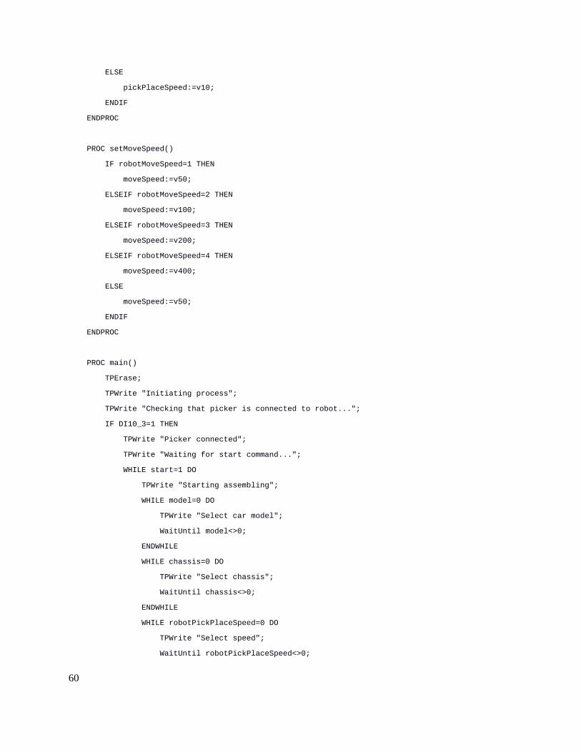
setPickPlaceSpeed()
It is used for define the speed applied in the pick and place movements of the robot. Can be set to
v10, v20, v30 or v40, depending on the value of robotPickPlaceSpeed. If none of the
latter are selected v10 is set by default.
setMoveSpeed()
Used for define the speed at which the robot should move between picks. Depends on the value
of robotMoveSpeed and can be set to v50, v100, v200 and v400. If none of the latter are
selected v50 is set by default.
40

7.4.3 Main Procedure
The flow in the main procedure was programmed in a way that goes from general to particular in
the assembly process of the car. Prior to this, it is important to make sure that the tool is
connected to the robot using an IF condition statement. The variables mentioned at the beginning
of the section must be set to their corresponding acceptable values in order for the program to
initiate the assembly routine. At the end of the assembly process all changes in the variables are
returned back to their default values. Between various steps there are text outputs, using
TPWrite, for the Flexpendant to display any errors occurring during the process of assembly.
The main procedure is listed together with the entire RAPID program in appendix A.
PROC main()
TPErase;
TPWrite "Initiating process";
TPWrite "Checking that picker is connected to robot...";
IF DI10_3=1 THEN
TPWrite "Picker connected";
TPWrite "Waiting for start command...";
WHILE start=1 DO
TPWrite "Starting assembling";
WHILE model=0 DO
TPWrite "Select car model";
WaitUntil model<>0;
ENDWHILE
WHILE chassis=0 DO
TPWrite "Select chassis";
WaitUntil chassis<>0;
ENDWHILE
41

WHILE robotPickPlaceSpeed=0 DO
TPWrite "Select speed";
WaitUntil robotPickPlaceSpeed<>0;
setPickPlaceSpeed;
ENDWHILE
setPickPlaceSpeed;
setMoveSpeed;
IF model=1 THEN
TPWrite "Select color of Block222";
WaitUntil Block222>0 AND Block222<=4;
TPWrite "Select color of Block232T";
WaitUntil Block232T>0 AND Block232T<=2;
Kombi chassis,Block232T,Block222;
ELSEIF model=2 THEN
TPWrite "Select color of Block232T";
WaitUntil Block232T>0 AND Block232T<=2;
Limousine chassis,Block232T;
ELSEIF model=3 THEN
TPWrite "Select color of Block232T";
WaitUntil Block232T>0 AND Block232T<=2;
Sportwagen chassis,Block232T;
ELSE
TPWrite "Model of auto do not exist";
ENDIF
DispatchAuto(model);
homepos;
TPWrite "End of the construction";
start:=0;
model:=0;
chassis:=0;
Block222:=0;
42
Block232T:=0;
ENDWHILE
ELSE
TPWrite "Please check the connection of the picker with the robot";
WaitTime 3;
Break;
ENDIF
ENDPROC
43

Chapter 8: Simulation and test in real robot.
8.1 Simulation test
Having created the RAPID program I proceeded to simulate it in the virtual robot cell already
designed in RobotStudio. For this simulation only the movements of the robot and the positions
of every pick and place were verified, using the virtual Flexpendant provided by the software.
Inputs could not be simulated due to the lack of permission of the virtual controller. The variables
were previously established. Because the lack of a gravity simulation in this software is not
possible to see the process of assembly 100% accurate like in real life, but the simulation helped
to look the movements and positioning of the robot.
Fig. 19 Simulation of the robot in RobotStudio.
44

Once tested the simulation I proceeded to transfer the program to the real controller. For this I
connected the PC with RobotStudio installed on it to the Ethernet port located in the front part of
the IRC5. On RobotStudio I used the “Add Controller“ option in the “Controller” tab. After the
connection was established I was able to transfer the RAPID file to the real controller.
8.2 Real robot test
For testing the program in the real robot, first I made sure everything was correctly connected
(power supply, data, flexpendant). After this I selected “Auto mode” and then turned on the
controller, and wait for the system to fully load on IRC5 and Flexpendant as well. With the
system on, I continue to check the program. First I need to set the values of each variable in order
for the process to start. The process of setting this variables is made through a serial connection
to the main computer of the IRC5. During the process of assembly in the real robot I realised that
the position of the tool are slightly misaligned, approximately 3 cm on x axis and y axis. After
seeing this I tried to find the cause of this error. First I measured the real structure and compared
it’s values with the CAD model used in RobotStudio. The hypothesis that the measured were not
equal in real and virtual environment was false. Then I had the theory that the cause of the error
was the calibration. So I calibrated the robot once again like described in section 5.5. After the
calibration was done I ran the RAPID code on the real robot once again. With the new calibration
the position of the tool was correct and the pick and place of blocks in the order programmed was
achieved. Several adjustments of the velocities had to be made to avoid the loose grip of
individual blocks or the fully assembled car. The machine is capable of assemble three different
models with 3 types of blocks and a combination of seven different colours. In continuous mode
the machine is capable of handle various request for assembling cars, executing the requests one
by one.
45
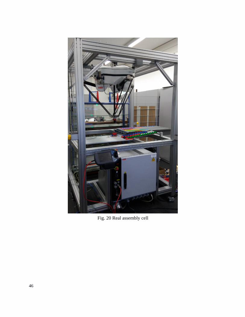
Fig. 20 Real assembly cell
46

8.3 Conclusions
After finishing the project some conclusions can be drawn regarding the programming in RAPID
of the Flexpicker:
The RAPID language offers a variety of functions to be used and perform many different tasks
with the robot manipulator, as well as flexibility in the creations of new user defined routines.
The program logic is easy to follow and because of the modularity of the procedures created, it
can be easily modified or extended to other uses.
The assembly of a car made with lego blocks using the Flexpicker robot was a success and it
proves the precision, reliability and flexibility of this robot in the process of modular assembly.
Calibration of the robot manipulator is essential to achieve the precision and repeatability
required in the assembly cell, due to this, instead of calibrating the robot manually I recommend
to use the specially designed tool ( Part no. 3HAC 9596-1) designed by ABB for the IRB 340
delta robot.
Poor calibration of a robot can lead to a misaligned tool either in RobotStudio or the real world
environment causing to make it more difficult to program the robot in offline mode.
The best way to program this type of robot is to combine the use of the Flexpendant and a PC
with RobotStudio. In RobotStudio is easier to create and modify the program logic, while with
the Flexpendant readjusting the position of the robot is more comfortable and easy to visualise.
Using a SysML model for complex systems leads to a better understanding of it because of its
graphical nature, which facilitate knowing the role of the cell components and their interface
between them. A basic SysML model was designed for this thesis and it serves its purpose of
showing the main components involved in the assembly cell. However the model can be extend
to describe more aspects of the robot cell.
47

References
[1] M. Wilson, “Introduction,” Implement. Robot Syst., pp. 1–18, 2015.
[2] I. Robotics, “Products - IFR International Federation of Robotics,” p. 2015, 2009.
[3] IFR, “Executive Summary of World Robotics 2016 Service Robots,” p. 8, 2016.
[4] J.-P. Merlet, Parallel Robots, vol. 208, no. 49. 2006.
[5] I. Bonev, “Delta parallel robot-the story of success,” Newsletter, no. 4, pp. 1–8, 2001.
[6] B. P. Douglass, Real-Time UML Workshop for Embedded Systems. 2014.
[7] T. Weilkiens, “Introduction,” Syst. Eng. with SysML/UML, pp. 1–22, 2007.
[8] S. Friedenthal, A. Moore, and R. Steiner, “Getting Started with SysML,” A Pract. Guid. toSysML, pp. 29–49, 2012.
[9] M. Nikolaidou, G. D. Kapos, A. Tsadimas, V. Dalakas, and D. Anagnostopoulos, “Simulating SysML models: Overview and challenges,” 2015 10th Syst. Syst. Eng. Conf. SoSE 2015, pp. 328–333, 2015.
[10] J. Huckaby, H. I. Christensen, and I. Machines, “A Case for SysML in Robotics,” IEEE Int. Conf. Autom. Sci. Eng., pp. 333–338, 2014.
[11] ABB, “IRB 340,” 2012.
[12] ABB, “IRC5 Industrial Robot Controller,” p. 4, 2016.
[13] ABB, “Product Specification - Controller IRC5,” p. 170, 2015.
[14] ABB, “Operator ’s Manual FlexPendant,” Screen, 2005.
[15] ABB, “Operating manual RobotStudio,” p. 588, 2016.
[16] ABB, “Product manual, procedures IRB 340,” pp. 4–5, 2003.
48
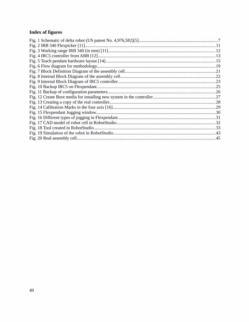
Index of figures
Fig. 1 Schematic of delta robot (US patent No. 4,976,582)[5].....................................................................7Fig. 2 IRB 340 Flexpicker [11]..................................................................................................................11Fig. 3 Working range IRB 340 (in mm) [11]..............................................................................................12Fig. 4 IRC5 controller from ABB [12].......................................................................................................13Fig. 5 Teach pendant hardware layout [14]................................................................................................15Fig. 6 Flow diagram for methodology........................................................................................................19Fig. 7 Block Definition Diagram of the assembly cell...............................................................................21Fig. 8 Internal Block Diagram of the assembly cell...................................................................................22Fig. 9 Internal Block Diagram of IRC5 controller......................................................................................23Fig. 10 Backup IRC5 on Flexpendant........................................................................................................25Fig. 11 Backup of configuration parameters..............................................................................................26Fig. 12 Create Boot media for installing new system in the controller.......................................................27Fig. 13 Creating a copy of the real controller.............................................................................................28Fig. 14 Calibration Marks in the four axis [16]..........................................................................................29Fig. 15 Flexpendant Jogging window.........................................................................................................30Fig. 16 Different types of jogging in Flexpendant......................................................................................31Fig. 17 CAD model of robot cell in RobotStudio.......................................................................................32Fig. 18 Tool created in RobotStudio...........................................................................................................33Fig. 19 Simulation of the robot in RobotStudio..........................................................................................43Fig. 20 Real assembly cell..........................................................................................................................45
49

Appendix A RAPID program.
MODULE Module1
!Variables
PERS num start:=0;
PERS num model:=0;
PERS num chassis:=0;
PERS num Block222:=0;
PERS num Block232T:=0;
PERS num robotPickPlaceSpeed:=0;
PERS num robotMoveSpeed:=0;
PERS num gripperTime:=1;
! internal speeddata linked to robotPickPlaceSpeed
VAR speeddata pickPlaceSpeed;
! internal speeddata linked to robotMoveSpeed
VAR speeddata moveSpeed;
! speeddata used on the first block layer for larger precision
CONST speeddata helperSpeed:=v10;
!!!!!! Blocks 2x2
CONST robtarget Block222GreenUp:=[[-128.48,298.75,-990.03],[0.707107,-0.707107,0.000132193,-0.000132193],[0,0,0,0],[9E9,9E9,9E9,9E9,9E9,9E9]];
CONST robtarget Block222GreenDown:=[[-128.46,298.78,-1039.51],[0.707107,-0.707107,0.000169479,-0.000169479],[0,0,0,0],[9E9,9E9,9E9,9E9,9E9,9E9]];
CONST robtarget Block222GreyUp:=[[-232.28,299.08,-1000.07],[0.707107,-0.707107,3.38928E-05,-3.38928E-05],[0,0,0,0],[9E+09,9E+09,9E+09,9E+09,9E+09,9E+09]];
CONST robtarget Block222GreyDown:=[[-232.28,299.09,-1039.67],[0.707107,-0.707107,3.05031E-05,-3.05031E-05],[0,0,0,0],[9E+09,9E+09,9E+09,9E+09,9E+09,9E+09]];
CONST robtarget Block222RedUp:=[[-198.63,299.47,-1000.02],[0.707107,-0.707107,3.38928E-05,-3.38928E-05],[0,0,0,0],[9E+09,9E+09,9E+09,9E+09,9E+09,9E+09]];
CONST robtarget Block222RedDown:=[[-198.63,299.47,-1039.84],[0.707107,-0.707107,4.06721E-05,-4.06721E-05],[0,0,0,0],[9E+09,9E+09,9E+09,9E+09,9E+09,9E+09]];
CONST robtarget Block222YellowUp:=[[-94.10,299.18,-1000.04],[0.707107,-0.707107,3.38928E-05,-3.38928E-05],[0,0,0,0],[9E+09,9E+09,9E+09,9E+09,9E+09,9E+09]];
CONST robtarget Block222YellowDown:=[[-94.09,299.18,-1039.38],[0.707107,-0.707107,3.38928E-05,-3.38928E-05],[0,0,0,0],[9E+09,9E+09,9E+09,9E+09,9E+09,9E+09]];
!!!!!!! Blocks 2x3
CONST robtarget Block232CyanUp:=[[-23.52,315.68,-990.25],[0.707107,-0.707107,0.00015592,-0.00015592],[0,0,0,0],[9E9,9E9,9E9,9E9,9E9,9E9]];
CONST robtarget Block232CyanDown:=[[-23.53,315.68,-1039.08],[0.707107,-0.707107,0.000149141,-0.000149141],[0,0,0,0],[9E9,9E9,9E9,9E9,9E9,9E9]];
CONST robtarget Block232TBlueUp:=[[-303.79,312.64,-1000.05],[0.707107,-0.707107,2.37238E-05,-2.37238E-05],[0,0,0,0],[9E+09,9E+09,9E+09,9E+09,9E+09,9E+09]];
50

CONST robtarget Block232TBlueDown:=[[-303.79,312.63,-1040.68],[0.707107,-0.707107,2.37238E-05,-2.37238E-05],[0,0,0,0],[9E+09,9E+09,9E+09,9E+09,9E+09,9E+09]];
CONST robtarget Block232TOrangeUp:=[[-337.37,312.55,-990.13],[0.707107,-0.707107,0.000122024,-0.000122024],[0,0,0,0],[9E9,9E9,9E9,9E9,9E9,9E9]];
CONST robtarget Block232TOrangeDown:=[[-337.35,312.55,-1039.83],[0.707107,-0.707107,0.000149141,-0.000149141],[0,0,0,0],[9E9,9E9,9E9,9E9,9E9,9E9]];
!!!!!!! Block 2x4
CONST robtarget Block242RedUp:=[[-197.62,299.39,-990.47],[0.707107,-0.707107,0.000132193,-0.000132193],[0,0,0,0],[9E9,9E9,9E9,9E9,9E9,9E9]];
CONST robtarget Block242RedDown:=[[-197.62,299.39,-1038.57],[0.707107,-0.707107,0.000138972,-0.000138972],[0,0,0,0],[9E9,9E9,9E9,9E9,9E9,9E9]];
!!!!!!! Chassis
CONST robtarget ChassisBlueUp:=[[184.28,164.11,-999.97],[0.707107,-0.707107,0.00015592,-0.00015592],[0,0,0,0],[9E9,9E9,9E9,9E9,9E9,9E9]];
CONST robtarget ChassisBlueDown:=[[184.28,164.12,-1094.31],[0.707107,-0.707107,0.0001627,-0.0001627],[0,0,0,0],[9E+09,9E+09,9E+09,9E+09,9E+09,9E+09]];
CONST robtarget ChassisGreenUp:=[[342.69,164.92,-1000.24],[0.707107,-0.707107,0.00015592,-0.00015592],[0,0,0,0],[9E9,9E9,9E9,9E9,9E9,9E9]];
CONST robtarget ChassisGreenDown:=[[342.7,164.92,-1092.77],[0.707107,-0.707107,0.000132193,-0.000132193],[0,0,0,0],[9E9,9E9,9E9,9E9,9E9,9E9]];
CONST robtarget ChassisRedUp:=[[264.71,164.12,-1000.63],[0.707107,-0.707107,0.000179648,-0.000179648],[0,0,0,0],[9E9,9E9,9E9,9E9,9E9,9E9]];
CONST robtarget ChassisRedDown:=[[264.71,164.11,-1093.1],[0.707107,-0.707107,0.000172868,-0.000172868],[0,0,0,0],[9E9,9E9,9E9,9E9,9E9,9E9]];
CONST robtarget ChassisWorkSpaceUp:=[[2.55,32.62,-1000.17],[0.707107,-0.707107,0.000047451,-0.000047451],[0,0,0,0],[9E9,9E9,9E9,9E9,9E9,9E9]];
CONST robtarget ChassisWorkSpaceDown:=[[2.55,32.63,-1100.2],[0.707107,-0.707107,0.00005762,-0.00005762],[0,0,0,0],[9E9,9E9,9E9,9E9,9E9,9E9]];
!!!!!!! Working positions
CONST robtarget home:=[[0.777,34.381,-932.5],[0.707106781,-0.707106781,0,0],[0,0,0,0],[9E9,9E9,9E9,9E9,9E9,9E9]];
CONST robtarget Pos1Up:=[[2.28,17.00,-1049.89],[0.707107,-0.707107,0.000362689,-0.000362689],[0,0,0,0],[9E+09,9E+09,9E+09,9E+09,9E+09,9E+09]];
CONST robtarget Pos1Down:=[[2.29,16.98,-1082.21],[0.707107,-0.707107,0.000362689,-0.000362689],[0,0,0,0],[9E+09,9E+09,9E+09,9E+09,9E+09,9E+09]];
CONST robtarget Pos1DownHelper:=[[2.27,17.00,-1064.96],[0.707107,-0.707107,0.00035252,-0.00035252],[0,0,0,0],[9E+09,9E+09,9E+09,9E+09,9E+09,9E+09]];
CONST robtarget Pos1DownHelper10:=[[2.28,16.99,-1071.15],[0.707107,-0.707107,0.000362689,-0.000362689],[0,0,0,0],[9E+09,9E+09,9E+09,9E+09,9E+09,9E+09]];
CONST robtarget Pos2Up:=[[4.36,80.03,-1000.03],[0.707107,-0.707107,0.000220324,-0.000220324],[0,0,0,0],[9E9,9E9,9E9,9E9,9E9,9E9]];
CONST robtarget Pos2Down:=[[3.23,64.43,-1081.61],[0.707107,-0.707107,0.000230493,-0.000230493],[0,0,0,0],[9E9,9E9,9E9,9E9,9E9,9E9]];
CONST robtarget Pos2DownHelper:=[[3.26,65.07,-1066.72],[0.707107,-0.707107,0.000213544,-0.000213544],[0,0,0,0],[9E9,9E9,9E9,9E9,9E9,9E9]];
CONST robtarget Pos2DownHelper10:=[[3.23,64.43,-1071.11],[0.707107,-0.707107,0.000230493,-0.000230493],[0,0,0,0],[9E9,9E9,9E9,9E9,9E9,9E9]];
CONST robtarget Pos3Up:=[[2.32,32.88,-1000.93],[0.707107,-0.707107,0.00015592,-0.00015592],[0,0,0,0],[9E9,9E9,9E9,9E9,9E9,9E9]];
51

CONST robtarget Pos3Down:=[[2.32,32.88,-1062.49],[0.707107,-0.707107,0.000132193,-0.000132193],[0,0,0,0],[9E9,9E9,9E9,9E9,9E9,9E9]];
CONST robtarget Pos4Up:=[[3.45,64.67,-1000.04],[0.707107,-0.707107,0.000091517,-0.000091517],[0,0,0,0],[9E9,9E9,9E9,9E9,9E9,9E9]];
CONST robtarget Pos4Down:=[[3.45,64.68,-1062.57],[0.707107,-0.707107,0.000132193,-0.000132193],[0,0,0,0],[9E9,9E9,9E9,9E9,9E9,9E9]];
CONST robtarget Pos5Up:=[[3.2,48.57,-1000.26],[0.707107,-0.707107,0.000088127,-0.000088127],[0,0,0,0],[9E9,9E9,9E9,9E9,9E9,9E9]];
CONST robtarget Pos5Down:=[[3.2,48.57,-1062.68],[0.707107,-0.707107,0.000074569,-0.000074569],[0,0,0,0],[9E9,9E9,9E9,9E9,9E9,9E9]];
CONST robtarget DispatchUp:=[[-213.89,34.38,-1000.29],[0.707107,-0.707107,3.05031E-05,-3.05031E-05],[0,0,0,0],[9E+09,9E+09,9E+09,9E+09,9E+09,9E+09]];
CONST robtarget DispatchDown:=[[-213.89,34.38,-1105.03],[0.707107,-0.707107,3.38928E-05,-3.38928E-05],[0,0,0,0],[9E+09,9E+09,9E+09,9E+09,9E+09,9E+09]];
PROC checkVacuum()
IF DI10_2 = 0 THEN
TPWrite "Problem with vacuum";
homepos;
Break;
ENDIF
ENDPROC
PROC pickBlock222Green()
MoveL Block222GreenUp,moveSpeed,fine,PickerFinal_2\WObj:=wobj0;
MoveL Block222GreenDown,pickPlaceSpeed,fine,PickerFinal_2\WObj:=wobj0;
SetDO DO10_1,1;
WaitTime gripperTime;
MoveL Block222GreenUp,moveSpeed,fine,PickerFinal_2\WObj:=wobj0;
checkVacuum;
ENDPROC
PROC pickBlock222Yellow()
MoveL Block222YellowUp,moveSpeed,fine,PickerFinal_2\WObj:=wobj0;
MoveL Block222YellowDown,pickPlaceSpeed,fine,PickerFinal_2\WObj:=wobj0;
SetDO DO10_1,1;
WaitTime gripperTime;
MoveL Block222YellowUp,moveSpeed,fine,PickerFinal_2\WObj:=wobj0;
checkVacuum;
ENDPROC
52

PROC pickBlock222Red()
MoveL Block222RedUp,moveSpeed,fine,PickerFinal_2\WObj:=wobj0;
MoveL Block222RedDown,pickPlaceSpeed,fine,PickerFinal_2\WObj:=wobj0;
SetDO DO10_1,1;
WaitTime gripperTime;
MoveL Block222RedUp,moveSpeed,fine,PickerFinal_2\WObj:=wobj0;
checkVacuum;
ENDPROC
PROC pickBlock222Grey()
MoveL Block222GreyUp,moveSpeed,fine,PickerFinal_2\WObj:=wobj0;
MoveL Block222GreyDown,pickPlaceSpeed,fine,PickerFinal_2\WObj:=wobj0;
SetDO DO10_1,1;
WaitTime gripperTime;
MoveL Block222GreyUp,moveSpeed,fine,PickerFinal_2\WObj:=wobj0;
checkVacuum;
ENDPROC
PROC pickBlock232Cyan()
MoveL Block232CyanUp,moveSpeed,fine,PickerFinal_2\WObj:=wobj0;
MoveL Block232CyanDown,pickPlaceSpeed,fine,PickerFinal_2\WObj:=wobj0;
SetDO DO10_1,1;
WaitTime gripperTime;
MoveL Block232CyanUp,moveSpeed,fine,PickerFinal_2\WObj:=wobj0;
checkVacuum;
ENDPROC
PROC pickBlock232TOrange()
MoveL Block232TOrangeUp,moveSpeed,fine,PickerFinal_2\WObj:=wobj0;
MoveL Block232TOrangeDown,pickPlaceSpeed,fine,PickerFinal_2\WObj:=wobj0;
SetDO DO10_1,1;
WaitTime gripperTime;
MoveL Block232TOrangeUp,moveSpeed,fine,PickerFinal_2\WObj:=wobj0;
checkVacuum;
ENDPROC
PROC pickBlock232TBlue()
MoveL Block232TBlueUp,moveSpeed,fine,PickerFinal_2\WObj:=wobj0;
MoveL Block232TBlueDown,pickPlaceSpeed,fine,PickerFinal_2\WObj:=wobj0;
53

SetDO DO10_1,1;
WaitTime gripperTime;
MoveL Block232TBlueUp,moveSpeed,fine,PickerFinal_2\WObj:=wobj0;
checkVacuum;
ENDPROC
PROC pickBlock242Red()
MoveL Block242RedUp,moveSpeed,fine,PickerFinal_2\WObj:=wobj0;
MoveL Block242RedDown,pickPlaceSpeed,fine,PickerFinal_2\WObj:=wobj0;
SetDO DO10_1,1;
WaitTime gripperTime;
MoveL Block242RedUp,moveSpeed,fine,PickerFinal_2\WObj:=wobj0;
checkVacuum;
ENDPROC
PROC pickChassisBlue()
MoveL ChassisBlueUp,moveSpeed,fine,PickerFinal_2\WObj:=wobj0;
MoveL ChassisBlueDown,pickPlaceSpeed,fine,PickerFinal_2\WObj:=wobj0;
SetDO DO10_1,1;
WaitTime gripperTime;
MoveL ChassisBlueUp,moveSpeed,fine,PickerFinal_2\WObj:=wobj0;
checkVacuum;
ENDPROC
PROC pickChassisGreen()
MoveL ChassisGreenUp,moveSpeed,fine,PickerFinal_2\WObj:=wobj0;
MoveL ChassisGreenDown,pickPlaceSpeed,fine,PickerFinal_2\WObj:=wobj0;
SetDO DO10_1,1;
WaitTime gripperTime;
MoveL ChassisGreenUp,moveSpeed,fine,PickerFinal_2\WObj:=wobj0;
checkVacuum;
ENDPROC
PROC pickChassisRed()
MoveL ChassisRedUp,moveSpeed,fine,PickerFinal_2\WObj:=wobj0;
MoveL ChassisRedDown,pickPlaceSpeed,fine,PickerFinal_2\WObj:=wobj0;
SetDO DO10_1,1;
WaitTime gripperTime;
MoveL ChassisRedUp,moveSpeed,fine,PickerFinal_2\WObj:=wobj0;
54

checkVacuum;
ENDPROC
PROC placeChassisWorkSpace()
MoveL ChassisWorkSpaceUp,moveSpeed,fine,PickerFinal_2\WObj:=wobj0;
MoveL ChassisWorkSpaceDown,pickPlaceSpeed,fine,PickerFinal_2\WObj:=wobj0;
SetDO DO10_1,0;
WaitTime gripperTime;
MoveL ChassisWorkSpaceUp,moveSpeed,fine,PickerFinal_2\WObj:=wobj0;
ENDPROC
PROC homepos()
SetDO DO10_1,0;
MoveL home,moveSpeed,fine,PickerFinal_2\WObj:=wobj0;
ENDPROC
PROC placePos1()
MoveL Pos1Up,moveSpeed,fine,PickerFinal_2\WObj:=wobj0;
MoveL Pos1DownHelper,pickPlaceSpeed,fine,PickerFinal_2;
MoveL Pos1DownHelper10,helperSpeed,fine,PickerFinal_2;
MoveL Pos1Down,pickPlaceSpeed,fine,PickerFinal_2\WObj:=wobj0;
SetDO DO10_1,0;
WaitTime gripperTime;
MoveL Pos1Up,moveSpeed,fine,PickerFinal_2\WObj:=wobj0;
ENDPROC
PROC placePos2()
MoveL Pos2Up,moveSpeed,fine,PickerFinal_2\WObj:=wobj0;
MoveL Pos2DownHelper,pickPlaceSpeed,fine,PickerFinal_2\WObj:=wobj0;
MoveL Pos2DownHelper10,helperSpeed,fine,PickerFinal_2;
MoveL Pos2Down,pickPlaceSpeed,fine,PickerFinal_2\WObj:=wobj0;
SetDO DO10_1,0;
WaitTime gripperTime;
MoveL Pos2DownHelper,pickPlaceSpeed,fine,PickerFinal_2\WObj:=wobj0;
MoveL Pos2Up,moveSpeed,fine,PickerFinal_2\WObj:=wobj0;
ENDPROC
PROC placePos3()
MoveL Pos3Up,moveSpeed,fine,PickerFinal_2\WObj:=wobj0;
55

MoveL Pos3Down,pickPlaceSpeed,fine,PickerFinal_2\WObj:=wobj0;
SetDO DO10_1,0;
WaitTime gripperTime;
MoveL Pos3Up,moveSpeed,fine,PickerFinal_2\WObj:=wobj0;
ENDPROC
PROC placePos4()
MoveL Pos4Up,moveSpeed,fine,PickerFinal_2\WObj:=wobj0;
MoveL Pos4Down,pickPlaceSpeed,fine,PickerFinal_2\WObj:=wobj0;
SetDO DO10_1,0;
WaitTime gripperTime;
MoveL Pos4Up,moveSpeed,fine,PickerFinal_2\WObj:=wobj0;
ENDPROC
PROC placePos5()
MoveL Pos5Up,moveSpeed,fine,PickerFinal_2\WObj:=wobj0;
MoveL Pos5Down,pickPlaceSpeed,fine,PickerFinal_2\WObj:=wobj0;
SetDO DO10_1,0;
WaitTime gripperTime;
MoveL Pos5Up,moveSpeed,fine,PickerFinal_2\WObj:=wobj0;
ENDPROC
PROC Kombi(num select1,num select2,num select3)
homepos;
IF select1=1 THEN
pickChassisBlue;
ELSEIF select1=2 THEN
pickChassisRed;
ELSEIF select1=3 THEN
pickChassisGreen;
ELSE
TPWrite "Chassis color do not exist";
ENDIF
placeChassisWorkSpace;
WaitDI DI10_1,0;
pickBlock232Cyan;
placePos1;
pickBlock232Cyan;
placePos2;
56

IF select2=1 THEN
pickBlock232TBlue;
ELSE
pickBlock232TOrange;
ENDIF
placePos3;
IF select3=1 THEN
pickBlock222Yellow;
ELSEIF select3=2 THEN
pickBlock222Green;
ELSEIF select3=3 THEN
pickBlock222Red;
ELSE
pickBlock222Grey;
ENDIF
placePos4;
ENDPROC
PROC Limousine(num select1,num select2)
homepos;
IF select1=1 THEN
pickChassisBlue;
ELSEIF select1=2 THEN
pickChassisRed;
ELSEIF select1=3 THEN
pickChassisGreen;
ELSE
TPWrite "Chassis color do not exist";
ENDIF
placeChassisWorkSpace;
WaitDI DI10_1,0;
pickBlock232Cyan;
placePos1;
pickBlock232Cyan;
placePos2;
IF select2=1 THEN
pickBlock232TBlue;
ELSE
pickBlock232TOrange;
57

ENDIF
placePos5;
ENDPROC
PROC Sportwagen(num select1,num select2)
homepos;
IF select1=1 THEN
pickChassisBlue;
ELSEIF select1=2 THEN
pickChassisRed;
ELSEIF select1=3 THEN
pickChassisGreen;
ELSE
TPWrite "Chassis color do not exist";
ENDIF
placeChassisWorkSpace;
WaitDI DI10_1,0;
IF select2=1 THEN
pickBlock232TBlue;
ELSE
pickBlock232TOrange;
ENDIF
placePos1;
pickBlock232Cyan;
placePos2;
ENDPROC
PROC DispatchAuto(num option)
IF option=1 THEN
MoveL Pos3Up,moveSpeed,fine,PickerFinal_2\WObj:=wobj0;
MoveL Pos3Down,pickPlaceSpeed,fine,PickerFinal_2\WObj:=wobj0;
SetDO DO10_1,1;
WaitTime gripperTime;
MoveL Pos3Up,moveSpeed,fine,PickerFinal_2\WObj:=wobj0;
WaitDI DI10_1,1;
MoveL DispatchUp,moveSpeed,fine,PickerFinal_2\WObj:=wobj0;
MoveL DispatchDown,moveSpeed,fine,PickerFinal_2\WObj:=wobj0;
SetDO DO10_1,0;
WaitTime gripperTime;
58

MoveL DispatchUp,moveSpeed,fine,PickerFinal_2\WObj:=wobj0;
ELSEIF option=2 THEN
MoveL Pos5Up,moveSpeed,fine,PickerFinal_2\WObj:=wobj0;
MoveL Pos5Down,pickPlaceSpeed,fine,PickerFinal_2\WObj:=wobj0;
SetDO DO10_1,1;
WaitTime gripperTime;
MoveL Pos5Up,moveSpeed,fine,PickerFinal_2\WObj:=wobj0;
WaitDI DI10_1,1;
MoveL DispatchUp,moveSpeed,fine,PickerFinal_2\WObj:=wobj0;
MoveL DispatchDown,moveSpeed,fine,PickerFinal_2\WObj:=wobj0;
SetDO DO10_1,0;
WaitTime gripperTime;
MoveL DispatchUp,moveSpeed,fine,PickerFinal_2\WObj:=wobj0;
ELSEIF option=3 THEN
MoveL Pos1Up,moveSpeed,fine,PickerFinal_2\WObj:=wobj0;
MoveL Pos1Down,pickPlaceSpeed,fine,PickerFinal_2\WObj:=wobj0;
SetDO DO10_1,1;
WaitTime gripperTime;
MoveL Pos1Up,moveSpeed,fine,PickerFinal_2\WObj:=wobj0;
WaitDI DI10_1,1;
MoveL DispatchUp,moveSpeed,fine,PickerFinal_2\WObj:=wobj0;
MoveL DispatchDown,moveSpeed,fine,PickerFinal_2\WObj:=wobj0;
SetDO DO10_1,0;
WaitTime gripperTime;
MoveL DispatchUp,moveSpeed,fine,PickerFinal_2\WObj:=wobj0;
ELSE
TPWrite "Error in dispatch option";
ENDIF
ENDPROC
PROC setPickPlaceSpeed()
IF robotPickPlaceSpeed=1 THEN
pickPlaceSpeed:=v10;
ELSEIF robotPickPlaceSpeed=2 THEN
pickPlaceSpeed:=v20;
ELSEIF robotPickPlaceSpeed=3 THEN
pickPlaceSpeed:=v40;
ELSEIF robotPickPlaceSpeed=4 THEN
pickPlaceSpeed:=v80;
59
ELSE
pickPlaceSpeed:=v10;
ENDIF
ENDPROC
PROC setMoveSpeed()
IF robotMoveSpeed=1 THEN
moveSpeed:=v50;
ELSEIF robotMoveSpeed=2 THEN
moveSpeed:=v100;
ELSEIF robotMoveSpeed=3 THEN
moveSpeed:=v200;
ELSEIF robotMoveSpeed=4 THEN
moveSpeed:=v400;
ELSE
moveSpeed:=v50;
ENDIF
ENDPROC
PROC main()
TPErase;
TPWrite "Initiating process";
TPWrite "Checking that picker is connected to robot...";
IF DI10_3=1 THEN
TPWrite "Picker connected";
TPWrite "Waiting for start command...";
WHILE start=1 DO
TPWrite "Starting assembling";
WHILE model=0 DO
TPWrite "Select car model";
WaitUntil model<>0;
ENDWHILE
WHILE chassis=0 DO
TPWrite "Select chassis";
WaitUntil chassis<>0;
ENDWHILE
WHILE robotPickPlaceSpeed=0 DO
TPWrite "Select speed";
WaitUntil robotPickPlaceSpeed<>0;
60
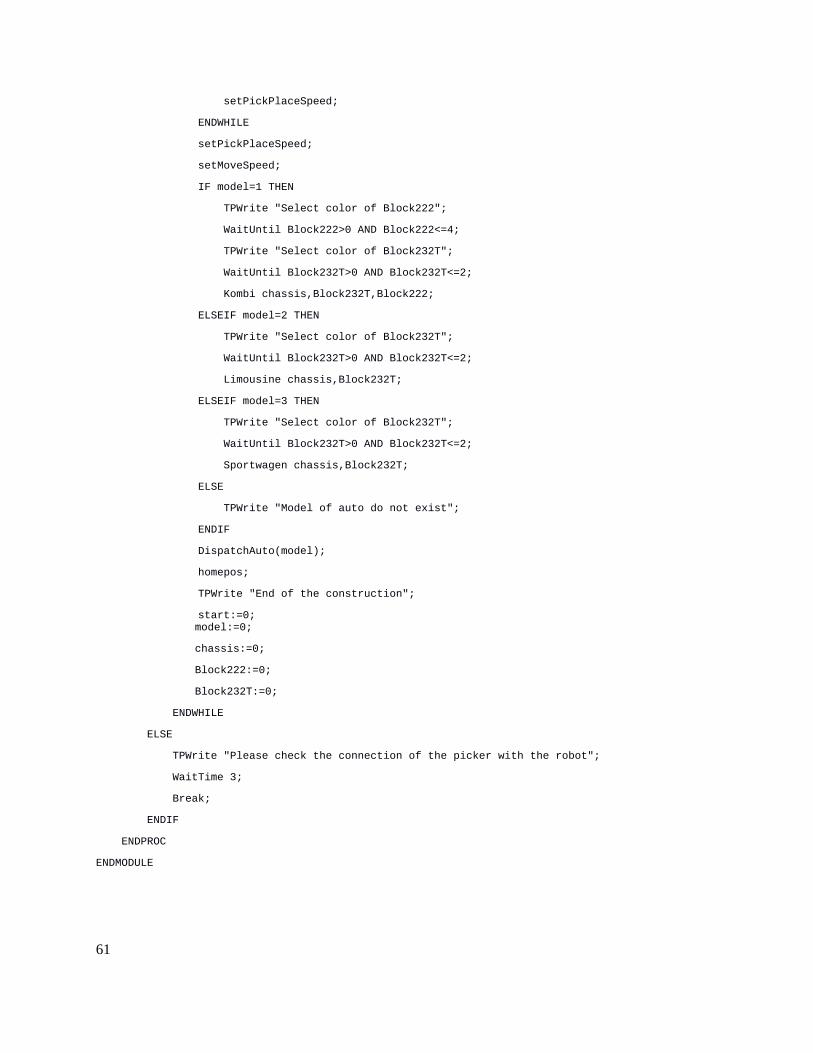
setPickPlaceSpeed;
ENDWHILE
setPickPlaceSpeed;
setMoveSpeed;
IF model=1 THEN
TPWrite "Select color of Block222";
WaitUntil Block222>0 AND Block222<=4;
TPWrite "Select color of Block232T";
WaitUntil Block232T>0 AND Block232T<=2;
Kombi chassis,Block232T,Block222;
ELSEIF model=2 THEN
TPWrite "Select color of Block232T";
WaitUntil Block232T>0 AND Block232T<=2;
Limousine chassis,Block232T;
ELSEIF model=3 THEN
TPWrite "Select color of Block232T";
WaitUntil Block232T>0 AND Block232T<=2;
Sportwagen chassis,Block232T;
ELSE
TPWrite "Model of auto do not exist";
ENDIF
DispatchAuto(model);
homepos;
TPWrite "End of the construction";
start:=0; model:=0;
chassis:=0;
Block222:=0;
Block232T:=0;
ENDWHILE
ELSE
TPWrite "Please check the connection of the picker with the robot";
WaitTime 3;
Break;
ENDIF
ENDPROC
ENDMODULE
61