Embed Size (px)
Citation preview

NAVAL POSTGRADUATE SCHOOL Monterey, California
THESIS
Approved for public release; distribution is unlimited.
3D VISUALIZATION OF TACTICAL COMMUNICATIONS FOR PLANNING AND OPERATIONS USING
VIRTUAL REALITY MODELING LANGUAGE (VRML) AND EXTENSIBLE 3D (X3D)
by
Michael G. Hunsberger
June 2001
Thesis Advisor: Don Brutzman Co-Advisors: Dave Laflam Dan Boger
3D VISUALIZATION OF TACTICAL COMMUNICATIONS FOR PLANNING AND OPERATIONS USING
VIRTUAL REALITY MODELING LANGUAGE (VRML) AND EXTENSIBLE 3D (X3D)
Michael G. Hunsberger-United States Air Force B.S. Rochester Institute of Technology, 1996
Master of Science System Technology–June 2001 Master of Science Computer Science-June 2001
Advisor: Don Brutzman, Department of Undersea Warfare Co-Advisor: David Laflam, United States Army Co-Advisor: Dan Boger, C4I Academic Group
The military is increasingly reliant on communication networks for day-to-day
tasks as well as large-scale military operations. Tactical communications networks are growing progressively more complex as the amount of information required on the battlefield increases. Communication planners require more advanced tools to perform and manage signal-planning activities. This work examines the use of 3D visualizations to assist in tactical signal planning. These visualizations are developed using Virtual Reality Modeling Language (VRML), Extensible 3D (X3D) graphics, and Distributed Information Simulation (DIS) for network connectivity.
These visualizations and the connectivity provide signal planners the ability to generate 3D scenarios quickly identifying problems such as frequency interference, connectivity problems, and marginal-coverage areas. Network connectivity also provides a collaborative planning environment for geographically dispersed units.
The NATO Global Hub Land C2 Information Exchange Data Model (LC2IEDM) is a semantic model designed for information passing between systems. This work also examines LC2IEDM for its ability to represent tactical communication plans and facilitate the autogeneration of 3D scenarios.
DoD KEY TECHNOLOGY AREA: command, control, communications, modeling, simulation KEYWORDS: 3D Visualizations, Virtual Reality Modeling Language (VRML), Extensible 3D (X3D), Tactical Communications, Communications Planning, NATO Global Hub, Land C2 Information Exchange Data Model (LC2IEDM)

i
REPORT DOCUMENTATION PAGE Form Approved OMB No. 0704-0188 Public reporting burden for this collection of information is estimated to average 1 hour
per response, including the time for reviewing instruction, searching existing data sources, gathering and maintaining the data needed, and completing and reviewing the collection of information. Send comments regarding this burden estimate or any other aspect of this collection of information, including suggestions for reducing this burden, to Washington headquarters Services, Directorate for Information Operations and Reports, 1215 Jefferson Davis Highway, Suite 1204, Arlington, VA 22202-4302, and to the Office of Management and Budget, Paperwork Reduction Project (0704-0188) Washington DC 20503. 1. AGENCY USE ONLY
2. REPORT DATE June 2001
3. REPORT TYPE AND DATES COVERED Master’s Thesis
4. TITLE AND SUBTITLE: 3D Visualization Of Tactical Communications For Planning And Operations Using Virtual Reality Modeling Language (VRML) And Extensible 3D (X3D) 6. AUTHOR Hunsberger, Michael, G.
5. FUNDING NUMBERS
7. PERFORMING ORGANIZATION NAME(S) AND ADDRESS(ES) Naval Postgraduate School Monterey, CA 93943-5000
8. PERFORMING ORGANIZATION REPORT NUMBER
9. SPONSORING / MONITORING AGENCY NAME(S) AND ADDRESS(ES) N/A
10. SPONSORING / MONITORING AGENCY REPORT NUMBER
11. SUPPLEMENTARY NOTES The views expressed in this thesis are those of the author and do not reflect the official policy or position of the Department of Defense or the U.S. Government. 12a. DISTRIBUTION / AVAILABILITY STATEMENT
Approved for public release; distribution is unlimited. 12b. DISTRIBUTION CODE
13. ABSTRACT
The military is increasingly reliant on communication networks for day-to-day tasks as well as large-scale military operations. Tactical communications networks are growing progressively more complex as the amount of information required on the battlefield increases. Communication planners require more advanced tools to perform and manage signal-planning activities. This work examines the use of 3D visualizations to assist in tactical signal planning. These visualizations are developed using Virtual Reality Modeling Language (VRML), Extensible 3D (X3D) graphics, and Distributed Information Simulation (DIS) for network connectivity.
These visualizations and the connectivity provide signal planners the ability to generate 3D scenarios quickly identifying problems such as frequency interference, connectivity problems, and marginal-coverage areas. Network connectivity also provides a collaborative planning environment for geographically dispersed units.
The NATO Global Hub Land C2 Information Exchange Data Model (LC2IEDM) is a semantic model designed for information passing between systems. This work also examines LC2IEDM for its ability to represent tactical communication plans and facilitate the autogeneration of 3D scenarios.
15. NUMBER OF PAGES
14. SUBJECT TERMS 3D Visualizations, Virtual Reality Modeling Language (VRML), Extensible 3D (X3D), Tactical Communications, Communications Planning, NATO Global Hub, Land C2 Information Exchange Data Model (LC2IEDM) 16. PRICE CODE
17. SECURITY CLASSIFICATION OF REPORT
Unclassified
18. SECURITY CLASSIFICATION OF THIS PAGE
Unclassified
19. SECURITY CLASSIFICATION OF ABSTRACT
Unclassified
20. LIMITATION OF ABSTRACT
UL
NSN 7540-01-280-5500 Standard Form 298 (Rev. 2-89) Prescribed by ANSI Std. 239-18

ii
THIS PAGE INTENTIONALLY LEFT BLANK
iii
Approved for public release; distribution is unlimited
3D VISUALIZATION OF TACTICAL COMMUNICATIONS FOR PLANNING AND OPERATIONS USING VIRTUAL REALITY MODELING LANGUAGE
(VRML) AND EXTENSIBLE 3D (X3D)
Michael G. Hunsberger Captain, United States Air Force
B.S., Rochester Institute of Technology, 1996
Submitted in partial fulfillment of the requirements for the degrees of
MASTER OF SCIENCE IN SYSTEMS TECHNOLOGY, JOINT C3 SYSTEMS
MASTER OF SCIENCE IN COMPUTER SCIENCE
from the
NAVAL POSTGRADUATE SCHOOL June 2001
Author: ___________________________________________ Michael G. Hunsberger
Approved by: ___________________________________________ Don Brutzman, Thesis Advisor
___________________________________________ Dave Laflam, Co-Advisor
___________________________________________ Dan Boger, Co-Advisor
Chair, C4I Academic Group and Chair, Computer Science Department

iv
THIS PAGE INTENTIONALLY LEFT BLANK

v
ABSTRACT
The military is increasingly reliant on communication networks for day-to-day
tasks as well as large-scale military operations. Tactical communications networks are
growing progressively more complex as the amount of information required on the
battlefield increases. Communication planners require more advanced tools to perform
and manage signal-planning activities. This work examines the use of 3D visualizations
to assist in tactical signal planning. These visualizations are developed us ing Virtual
Reality Modeling Language (VRML), Extensible 3D (X3D) graphics, and Distributed
Information Simulation (DIS) for network connectivity.
These visualizations and the connectivity provide signal planners the ability to
generate 3D scenarios quickly identifying problems such as frequency interference,
connectivity problems, and marginal-coverage areas. Network connectivity also provides
a collaborative planning environment for geographically dispersed units.
The NATO Global Hub Land C2 Information Exchange Data Model (LC2IEDM)
is a semantic model designed for information passing between systems. This work also
examines LC2IEDM for its ability to represent tactical communication plans and
facilitate the autogeneration of 3D scenarios.

vi
THIS PAGE INTENTIONALLY LEFT BLANK

vii
TABLE OF CONTENTS
I. INTRODUCTION........................................................................................................1 A. THESIS STATEMENT...................................................................................1 B. OVERVIEW.....................................................................................................1 C. OBJECTIVES ..................................................................................................3 D. ORGANIZATION OF THESIS .....................................................................3
II. BACKGROUND AND RELATED WORK ..............................................................7 A. INTRODUCTION............................................................................................7 B. TECHNOLOGY ..............................................................................................7
1. Extensible Markup Language (XML)................................................7 2. Virtual Reality Modeling Language (VRML) / Extensible 3D
(X3D) .....................................................................................................8 3. IEEE Distributed Interactive Simulation (DIS) ................................8
C. COMMUNICATION TOOLS ........................................................................9 1. U.S. Marine Corps System Planning, Engineering and
Evaluation Device (SPEED) ..............................................................10 2. US Army Mobile Subscriber Equipment – Network Planning
Terminal (MSE-NPT)........................................................................11 3. Satellite Tool Kit (STK) .....................................................................12 4. Edge Product Family by Autometric, Inc. .......................................13 5. Ontar Corporation Family of Products ...........................................14
D. MILITARY PLANNING METHODOLOGIES.........................................15 1. Operations Orders .............................................................................15 2. Communications Annex ....................................................................15
E. CHAPTER SUMMARY................................................................................16
III. VIRTUAL REALITY MODELING LANGUAGE (VRML), EXTENSIBLE MARKUP LANGUAGE (XML), AND EXTENSIBLE 3D (X3D) GRAPHICS.................................................................................................................17 A. INTRODUCTION..........................................................................................17 B. VIRTUAL REALITY MODELING LANGUAGE (VRML) ....................17
1. Visual Nodes .......................................................................................19 2. Grouping Nodes .................................................................................23 3. Viewing and NavigationInfo Nodes..................................................24 4. Behavior and Event Model................................................................26 5. Interpolators Node and ROUTEs .....................................................27 6. Sensor Nodes.......................................................................................28 7. Script Node .........................................................................................28 8. PROTO and EXTERNPROTO Definitions ....................................29
C. GEOVRML.....................................................................................................29 1. GeoOrigin ...........................................................................................32 2. GeoLocation........................................................................................32 3. GeoPositionInterpolator....................................................................32 4. GeoViewpoint .....................................................................................33
viii
D. EXTENSIBLE MARKUP LANGUAGE (XML) ........................................33 E. EXTENSIBLE 3D (X3D)...............................................................................34 F. CHAPTER SUMMARY................................................................................37
IV. SCENARIO VISUALIZATION ...............................................................................39 A. INTRODUCTION..........................................................................................39 B. VISUALIZATION .........................................................................................39
1. Scientific Visualization ......................................................................39 2. Information Visualization .................................................................40
C. 3D GRAPHICS PALETTE...........................................................................41 1. Color and Textures ............................................................................41 2. Size and Distance................................................................................42 3. Navigation...........................................................................................42 4. Animation ...........................................................................................42
D. RADIO COMMUNICATION ......................................................................43 E. SCENARIO VISUALIZATION ...................................................................45
1. Very High Frequency (VHF) Communication Systems .................45 2. Ultra High Frequency (UHF) Communication Systems ................46 3. Super High Frequency (SHF) Communication Systems ................46 4. Satellite Systems .................................................................................47
F. CHAPTER SUMMARY................................................................................48
V. SHARED VISUALIZATION OF RADIO CHARACTERISTICS USING DISTRIBUTED INTERACTIVE SIMULATION (DIS) .......................................49 A. INTRODUCTION..........................................................................................49 B. DISTRIBUTED INTERACTIVE SIMULATION (DIS) PROTOCOL
DATA UNIT (PDU) CATEGORIES............................................................49 1. Entity Information/Interaction PDUs ..............................................49 2. Warfare PDUs ....................................................................................50 3. Logistics PDUs ....................................................................................50 4. Simulation Management PDUs .........................................................50 5. Distributed Emission Regeneration PDUs .......................................51 6. Radio Communications PDUs ..........................................................51
C. RADIO COMMUNICATION FAMILY PROTOCOL DATA UNITS....51 1. Transmitter PDU................................................................................52 2. Receiver PDU......................................................................................53 3. Signal PDU..........................................................................................54
D. PDU VISUALIZATION ................................................................................55 E. DIS-JAVA-VRML .........................................................................................56 F CHAPTER SUMMARY................................................................................58
VI. OPERATIONS AND COMMUNICATIONS PLANNING...................................59 A. INTRODUCTION..........................................................................................59 B. OPERATIONS PLANNING.........................................................................59
1. Strategic Level....................................................................................60 2. Operational Level...............................................................................60 3. Tactical Level......................................................................................60

ix
C. OPERATION ORDER (OPORD)................................................................60 D. RADIO COMMUNICATION PLANNING................................................62 E. ANNEX K - COMMAND, CONTROL, COMMUNICATION, AND
COMPUTER (C4) SYSTEMS ......................................................................65 F. CHAPTER SUMMARY................................................................................65
VII. MODELING COMMUNICATIONS PLANNING AND OPERATIONS USING THE NATO LAND C2 INFORMATION EXCHANCE DATA MODEL (LC2IEDM) ................................................................................................67 A. INTRODUCTION..........................................................................................67 B. DATA INTERCHANGE ...............................................................................67 C. GENERIC HUB ..............................................................................................69 D. LAND C2 INFORMATION EXCHANGE DATA MODEL
(LC2IEDM).....................................................................................................70 E. THE COMMUNICATIONS-ELECTRONICS EXTENSION FOR
MODELING COMMUNICATION PLANNING AND OPERATIONS ...............................................................................................71
F. COMMUNICATIONS-ELECTRONICS EXTENSION EXAMPLES ....73 1. Two-Node Network (Example A) .....................................................73 2. Four-Node Network (Example B).....................................................74
G. CHAPTER SUMMARY................................................................................76
VIII. DEMONSTRATION OF SIMULATION RESULTS ............................................77 A. INTRODUCTION..........................................................................................77 B. DEMONSTRATION OF VISUALIZATION TECHNIQUES..................77
1. Signal Primitives ................................................................................77 2. System Visualization..........................................................................79 3. Scenario Visualization .......................................................................83
C. USE OF VISUALIZATION IN COMMUNICATION PLANNING AND OPERATIONS .....................................................................................85
D. CHAPTER SUMMARY................................................................................86
IX. CONCLUSIONS AND RECOMMENDATIONS...................................................87 A. INTRODUCTION..........................................................................................87 B. THESIS CONCLUSIONS.............................................................................87
1. 3D Tactical Visualization Of Communications ...............................87 2. Open-Source Software Toolkits ........................................................88 3. Operation Orders Using The Global Hub Data Model..................88
C. RECOMMENDED FUTURE WORK.........................................................88 1. Physics-Based Signal Propagation....................................................88 2. Dynamic 3D Terrain Visualization...................................................88 3. Autogeneration of 3D from an Operation Order Annex K............89 4. Virtual Reality Toolbox .....................................................................89 5. MathML..............................................................................................89

x
APPENDIX A. ABBREVIATIONS............................................................................91
APPENDIX B. SOFTWARE AVAILABILITY AND INSTALLATION SUMMARY........................................................................................93
APPENDIX C. SIGNAL PROTOTYPES ...ERROR! BOOKMARK NOT DEFINED.
APPENDIX D. OMNI DIRECTIONAL COMMUNICATION PROTOTYPES.121
APPENDIX E. TROPOSPHERIC SATELLITE SUPPORT RADIO (TSSR) PROTOTYPES ................................................................................167
APPENDIX F. TRC-170 TROPOSPHERIC SCATTER MICROWAVE RADIO TERMINAL PROTOTYPES ...........................................213
APPENDIX G. TERRAIN DEVELOPMENT CODE ............................................245
LIST OF REFERENCES ....................................................................................................267
INITIAL INITIAL DISTRIBUTION LIST ......................................................................271

xi
LIST OF FIGURES
Figure 2.1 BattleScape Visualization Scene Showing Coverage Areas for Aircraft and Satellites, Ref. (Autometrics, 2001)................................................... 14 Figure 3.1 “Hello World” Source Code and Rendered World, From (Brutzman, 1998) ...................................................................................... 19 Figure 3.2 Tropo Satellite Support Radio (TSSR) Built Using Primitive Shapes ..... 20 Figure 3.3 Aerial View of Las Pulgas Beach at Camp Pendelton, California
Generated from National Imaging and Mapping Agency (NIMA) Digital Terrain Elevation Data (DTED) using a Matlab Script, After (Brutzman, Blais, 2001)................................................................... 22 Figure 3.4 Beach Level View of Las Pulgas Beach, Camp Pendelton, California .... 23 Figure 3.5 Cosmo Software VRML Plug-In .............................................................. 25 Figure 3.6 Chomp Demo for 3-Space Navigation Practice (Silicon Graphics, 1998) 26 Figure 3.6 X3D Source Code and Rendering for GeoVRMLWorld.wrl, From
(Murray, 2000).......................................................................................... 31 Figure 3.7 Screen capture of X3D-Edit Tool, From (Brutzman, 2000) ..................... 36 Figure 3.8 VRML (left) and X3D (right) Source Code for "Hello World", From
(Brutzman, 1999) ...................................................................................... 37 Figure 4.1 Radio Spectrum Frequency Bands, After (Neuhaus, 2001)...................... 44 Figure 5.1 SPEED Radio Coverage Analysis Tool showing Center Radio Coverage64 Figure 5.2 SPEED Radio Coverage Tool Displaying Common Line of Sight
Coverage Area for all Three Radios ......................................................... 64 Figure 6.1 Generic Hub and Its Relationship to Subfunctional Areas, From (NATO,
2000) ......................................................................................................... 70 Figure 6.2 Communication-Electronics Entities, From (NATO, 2000) ..................... 72 Figure 6.3 Two Examples of Logical Networks, After (NATO, 2000) ..................... 73 Figure 8.1 Beam Cone and Beam Cylinder Signal Prototypes Shown as Solid and Wire Frame Objects ........................................................................... 78 Figure 8.2 Two Area-Coverage Domes...................................................................... 79 Figure 8.3 Two Tropo Satellite Support Radios (TSSR) with an Established Direct-Path Link........................................................................................ 80 Figure 8.4 High Above Two TRC-170s Operating in Troposcatter Mode ................ 81 Figure 8.5 Omni Directional Receivers and Transmitters with the Two Larger Domes Indicating Active Communication................................................ 82 Figure 8.6 Satellite Ground Station With Transmitting Cone Shown From Above .. 83 Figure 8.7 3 Advanced Amphibious Assault Vehicles Shown Communicating After Launching from the Landing Platform-Docking ............................. 84 Figure 8.8 Follow-on Communication using Troposcatter Satellite Support Radios and TRC-170 in Troposcatter Mode ............................................. 85

xii
THIS PAGE INTENTIONALLY LEFT BLANK

xiii
LIST OF TABLES
Table 4.1 Frequency Ranges and Usage of the Radio Spectrum in the United States, After (Laflam, 2000).......................................................... 44 Table 6.1 Two Node Network Example Expressed using Global Hub Notation, From (NATO, 2000) ................................................................................. 74 Table 6.2 Four Node Network Example Expressed using Global Hub Notation, From (NATO, 2000) ................................................................................. 75

xiv
THIS PAGE INTENTIONALLY LEFT BLANK
1
I. INTRODUCTION
A. THESIS STATEMENT
Virtual Reality Modeling Language (VRML) and Extensible 3D (X3D) graphics
provide a framework that can be used to visualize tactical radio communications in a
three-dimensional (3D) battlespace. These visualizations can enhance both the
communication planning process and battlespace awareness.
B. OVERVIEW
The development of Large-Scale Virtual Environments (LSVEs) representing a
military battlefield has long been the goal of military researchers. Such LSVEs allow
distributed users to view training and operational situations in 3D. These environments
can facilitate more realistic training and increased battlespace awareness by allowing
users to view the total situation from any vantage point in a realistic fashion.
Rapid rendering of high-resolution 3D models previously required specialized
graphics hardware that was prohibitively expensive for adoption on a large scale. As
computer power has increased however, interactive 3D models are now able to run on
commodity personal computers (PCs). This thesis demonstrates 3D tactical
communication visualizations and models that can be integrated into LSVEs for signal
planning and battlespace awareness.
Computer ne tworks have grown larger and more complex in the past several
years. Military tactical networks are no exception. Military operations are increasingly
dependent on information and networks as forces shift to Network Centric Warfare

2
(NCW) (Cebrowski, 1997). Tactical radio networks provide operational capabilities for
mobile, dispersed units where no fixed infrastructure exists. Such networks increasingly
contain interconnections of multiple sites using different types of equipment.
One challenge in utilizing tactical radio networks is the ability for the
communications planner and commander to understand the complex organization of the
network. Current planning systems use two-dimensional (2D) cartographic
representations of the three dimensional (3D) operations space. By creating a 3D model
of a communications plan, the planner can view the plan as a whole from different
perspectives. The planner can also convey this information to other communicators and
the operators they are supporting.
Virtual Reality Modeling Language (VRML) is a Web-based graphics language
for creating 3D models. VRML allows user interaction with a scene through navigation
controls and predefined viewpoints. One of the key features of VRML is it is a non-
proprietary ISO standard designed for use over the World Wide Web (VRML, 1997).
Extensible 3D (X3D) is the next generation specification of VRML (Extensible
3D Task Group, 2001). It incorporates Extensible Markup Language (XML) encoding of
the VRML97 specification (World Wide Web Consortium (W3C), 1997). X3D provides
the benefits of extensibility, componentization, and the ability to developed well- formed
and validated scene graphs. X3D is backwards compatible with the VRML97
specification.
The VRML / X3D languages contain a rich set of tools for visualizing
information. The VRML /X3D graphics palette includes shapes, colors, textures,
luminescence, and animations that can be used to create 3D scenes. VRML / X3D is

3
used extensively throughout this thesis to create exemplar models illustrating potential
solutions.
The systems capability to portray a common representation for operational and
planning data facilitates increases interoperability. The North Atlantic Treaty
Organization (NATO) Land C2 Information Exchange Data Model (LC2IEDM) proposal
is a data model for exchanging information between systems (NATO, 2000). It is an
attempt to have all NATO countries implement a common method for exchanging data
between independent systems. This could prove useful for the autogeneration of 3D
visual planning models. The Generic Hub will be evaluated will be examined with
respect to its communication object representation.
C. OBJECTIVES
The objective of this thesis is to demonstrate the viability of using Virtual Reality
Modeling Language (VRML) and Extensible 3D (X3D) graphics to create a 3D
battlespace for visualizing tactical communications. To develop a tactical
communication visualization framework, the following components must be developed:
• VRML Prototype libraries representing the different communication systems that can be added to other virtual environments
• Scientific visualization approach to rendering communications links
• Realistic tactical battlefield in VRML for display of communication systems
D. ORGANIZATION OF THESIS
This thesis is organized as follows:
4
• Chapter II: Background. This chapter introduces the relevant
components for the creation a 3D visualization framework. It also
discusses some of the tools currently being used for military visualization.
Operation and communication planning methodologies are also
examined.
• Chapter III: Extensible Markup Language (XML), Virtual Reality
Modeling Language (VRML), and Extensible 3D (X3D). This chapter
provides an in-depth look at the underlying tools used to create 3D
visualizations for the web.
• Chapter IV: Scenario Visualization. This chapter describes the
process of scenario visualization by examining tactical communication
systems.
• Chapter V: Parameter Visualization. This chapter describes the
process of individual signals visualization using IEEE Distributed
Interactive Simulation (DIS) specification.
• Chapter VI: Operations and Communications Planning. This chapter
examines the military methodologies for operation and communications
planning.
• Chapter VII: Modeling Communications Planning and Operations
Using the NATO Land C2 Information Exchance Data Model
(LC2IEDM). This chapter examines the LC2IEDM for suitability of
representing tactical communication planning and operations.

5
• Chapter VIII: Demonstration of Results. This chapter describes,
presents, and evaluates the communication visualizations produced during
this thesis.
• Chapter IX: Conclusions and Recommendations. This chapter
summarizes the conclusions and recommendations for future work on
tactical communication visualization.

6
THIS PAGE INTENTIONALLY LEFT BLANK

7
II. BACKGROUND AND RELATED WORK
A. INTRODUCTION
This chapter reviews the fundamental concepts and technology underlying 3D
visualization of communication signals. This chapter introduces the tools and
technologies used within this thesis for generating 3D visualizations. It also presents
some of the current communications planning systems that are used within the
Department of Defense. A brief overview of military operations and communication
systems planning tools are also presented.
B. TECHNOLOGY
This section provides a brief introduction to some of the technology that enables
3D visualization and battlefield simulation using computer networks. These tools are
Extensible Markup Language (XML), Virtual Reality Modeling Language (VRML), the
next-generation VRML encoding Extensible 3D (X3D), and Distribute Interactive
Simulation (DIS), the distributed networking simulation standard. These computer
languages and protocols allow for the description of shared 3D models and the
distribution of simulation information over computer networks.
1. Extensible Markup Language (XML)
Extensible Markup Language (XML) is a markup language and World Wide Web
(WWW) standard defined by the World Wide Web Consortium (W3C). XML is a
markup language that provides structural information for documents. This structure
defines the precise roles and relationships in which the information must follow within

8
the document. A markup language defines the structure of a particular document. The
XML specification defines a standard way to add markup to documents (Walsh, 1998).
XML differs from other markup languages because it does not directly specify how
information is to be presented, but rather defines the structure (and thus semantics) of the
information.
2. Virtual Reality Modeling Language (VRML) / Extensible 3D (X3D)
The Virtual Reality Modeling Language (VRML) is a descriptive computer
language designed to facilitate the creation of 3D objects and worlds. VRML is similar
to the Hypertext Markup Language (HTML) in that it allows viewing and user interaction
using a standard web browser. VRML 97 is the current published International Standards
Organization (ISO) standard for the VRML language. Extensible 3D (X3D) is the next-
generation VRML specification. X3D extends the functionality of VRML by rewriting
the VRML code with an XML encoding and adding new nodes.
3. IEEE Distributed Interactive Simulation (DIS)
Distributed Interactive Simulation (DIS) is a government/industry/academic
initiative, maintained by the Institute of Electrical and Electronic Engineers (IEEE), to
define the infrastructure linking distributed simulations. The DIS standards are contained
in the IEEE 1278 family of documents. The DIS Application Protocols in IEEE 1278.1-
1995 contain communication protocols used to standardize the way information about a
simulation is passed between computers on the simulation network. DIS protocols also
specify the way information is packetized and transmitted ‘over-the-wire’ of the network.
The DIS protocols are an outgrowth of simulator-network (SIMNET) research
completed for the Defense Advanced Research Projects Agency (DARPA). Bolt,

9
Beranek, and Newman conducted SIMNET research in the late 1980s. SIMNET’s goal
was to create a virtual battlefield by linking numerous computers together. The DIS
protocols have drawn on the experience and lessons learned from SIMNET.
DIS is designed for both interactivity and distributed computing on different types
of computer operating systems and networks architectures. Simulations will proceed
correctly as long as each computer has implemented the DIS protocol correctly. The DIS
standard specifies a set of messages or Protocol Data Units (PDUs) that contain ordered
data fields conveying state information about the entities in the simulation. The state
information fields are states such as speed, location, orientation, and acceleration for
simulated entities. DIS packets usually rely on multicast for the network transport
protocol. Multicast reduces the number of redundant packets sent over the network
through the use of traffic grouping techniques, thus reducing the overhead of the
simulation.
Ongoing work with DIS can be found in several symposia series, including: IEEE
International Workshop on Distributed Simulations and Real Time Applications.
C. COMMUNICATION TOOLS
The next section details several communication planning and visualization tools
currently being used within DoD. The tools are System Planning, Engineering and
Evaluation Device (SPEED), Mobile Subscribe Equipment- Network Planning Tool
(MSE-NPT), Satellite Toolkit (STK), and the Edge Product Family. This thesis surveys
these available tools and examines their ability to visualize radio signals in 2D or 3D.
10
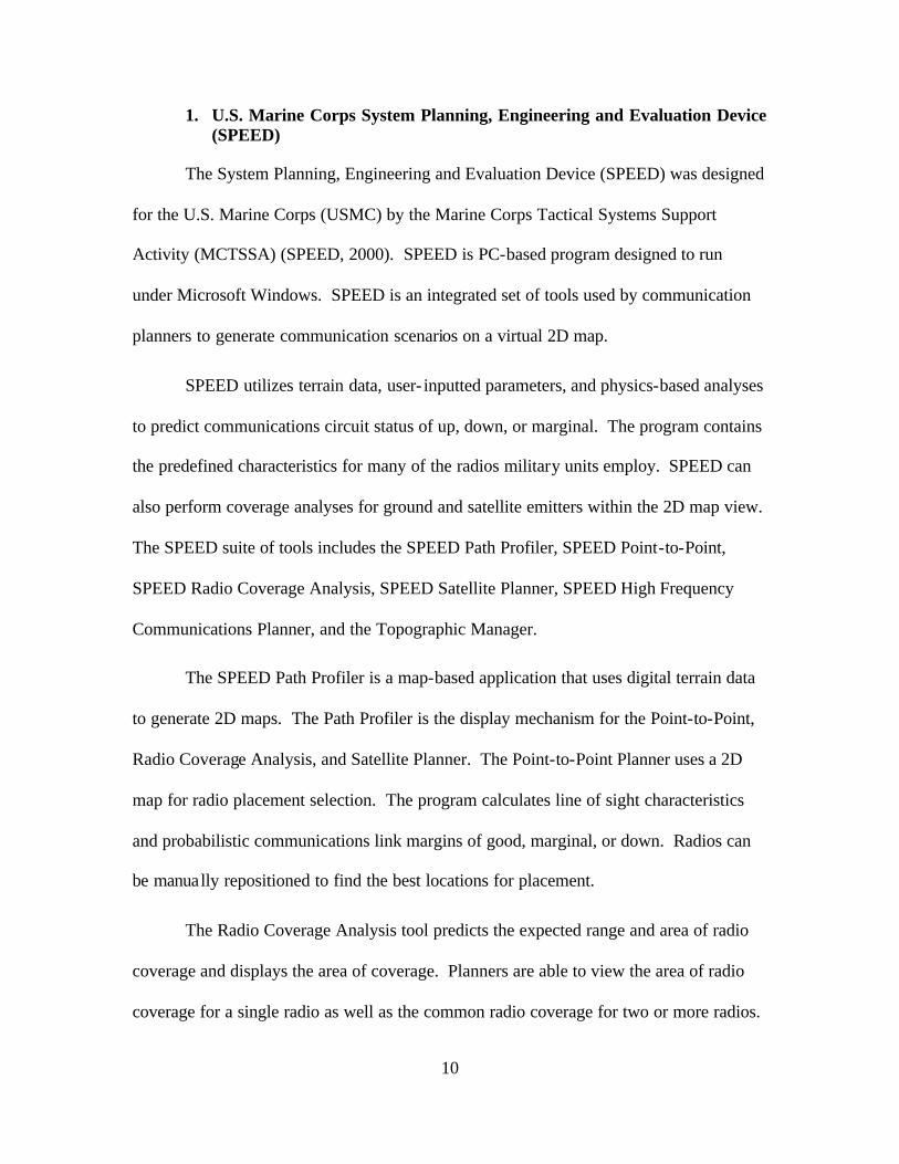
1. U.S. Marine Corps System Planning, Engineering and Evaluation Device (SPEED)
The System Planning, Engineering and Evaluation Device (SPEED) was designed
for the U.S. Marine Corps (USMC) by the Marine Corps Tactical Systems Support
Activity (MCTSSA) (SPEED, 2000). SPEED is PC-based program designed to run
under Microsoft Windows. SPEED is an integrated set of tools used by communication
planners to generate communication scenarios on a virtual 2D map.
SPEED utilizes terrain data, user- inputted parameters, and physics-based analyses
to predict communications circuit status of up, down, or marginal. The program contains
the predefined characteristics for many of the radios military units employ. SPEED can
also perform coverage analyses for ground and satellite emitters within the 2D map view.
The SPEED suite of tools includes the SPEED Path Profiler, SPEED Point-to-Point,
SPEED Radio Coverage Analysis, SPEED Satellite Planner, SPEED High Frequency
Communications Planner, and the Topographic Manager.
The SPEED Path Profiler is a map-based application that uses digital terrain data
to generate 2D maps. The Path Profiler is the display mechanism for the Point-to-Point,
Radio Coverage Analysis, and Satellite Planner. The Point-to-Point Planner uses a 2D
map for radio placement selection. The program calculates line of sight characteristics
and probabilistic communications link margins of good, marginal, or down. Radios can
be manually repositioned to find the best locations for placement.
The Radio Coverage Analysis tool predicts the expected range and area of radio
coverage and displays the area of coverage. Planners are able to view the area of radio
coverage for a single radio as well as the common radio coverage for two or more radios.

11
This tool also determines the coverage for a Position Locating and Reporting System
(PLRS) network with PLRS Area Analysis tool.
The Satellite Planner is used to plan and evaluate satellite links based on proposed
locations for satellite communication terminals. Satellite Planner can operate with both
geostationary and non-geostationary satellites. The Topographic Manager is designed to
manage the use of Digital Terrain Elevation Data (DTED) obtained from the National
Imaging and Mapping Agency (NIMA). DTED is elevation data available for much of
the earth’s surface at differing resolutions. Topographic Manager processes the DTED,
which is then used for line-of-sight (LOS) calculations throughout the SPEED program.
2. US Army Mobile Subscriber Equipment – Network Planning Terminal (MSE-NPT)
The US Army Mobile Subscriber Equipment (MSE) – Network Planning
Terminal (NPT) is a set of radio-profiling software and hardware that was developed
under a contract for the CECOM (MSE-NPT, 1997). All Army tactical units that have
MSE transmission equipment use MSE-NPT. Some Air Force tactical communication
units also use MSE-NPT.
MSE-NPT provides the communication planners an object-oriented approach for
creating communication plans. Operators create networking plans using the 2D graphical
user interface (GUI). The operator must have knowledge of the specific radios and their
capabilities. Once a user has completed a network design with specific locations for the
transmission equipment, MSE-NPT will provide a detailed analysis of the network using
terrain profiling. The detailed analysis includes link margins, propagation loss, path
reliability, FRESNEL zone clearance, multi path effects, and climate factors. MSE-NPT
uses NIMA DTED products to calculate terrain effects on user-designed networks. MSE-

12
NPT outputs its findings using on a 2D color display with the network overlaid on the
terrain map.
3. Satellite Tool Kit (STK)
Satellite Tool Kit (STK) is a space and communication planning and visualization
tool suite designed by Analytical Graphics, Inc (AGI, 2001). Primarily designed as a
satellite and space design and evaluation tool, STK has been consistently upgraded to
incorporate communication, radio, and command and control modules. STK is the core
tool of the software suite. It is designed to run on a PC or Unix platform. The STK core
software tool has been recently released as freeware software product with some
additional modules available for a fee. STK is available at (www.stk.com).
The STK core tool is used throughout the Department of Defense Space Units for
analysis of all types of space missions. STK provides modeling and visualization for
these mission types. It also provides modules for communications and enhanced
visualization. STK also supports DIS networking.
The communication module (STK/Comm) provides analysis of the quality of
communication links. The three main functions of the Comm module are to: provide
link analyses for all orbit types, including geostationary and Low Earth Orbiting (LEO)
spacecraft; generate contour plots of critical communications parameters; and model
radio interference (AGI, 2000). As military communications systems become more
complex with communications reachback and tactical satellite use, the end-to-end
analysis of communications systems is increasingly important.
The STK visualization module (STK/VO) is designed to provide both 2D and 3D
communication and space scenarios. The STK / Advanced VO module also provides

13
high definition 3D imaging for video production and terrain visualization. STK/VO is
also capable of performing scenario fly through to visualize relationships between objects
within a scenario.
4. Edge Product Family by Autometric, Inc.
Autometric, Inc. (acquired by Boeing in August, 2000) developed a 2D and 3D
visualization and analysis toolkit called the Edge Product Family. The Edge Product
Family is a Microsoft Windows-based platform providing Battlespace Situational
Awareness, Intelligence Analysis, Decision Support, and Intelligence Surveillance
Reconnaissance Collection Support. Edge is tightly coupled with Microsoft Office
products to facilitate data interchange.
Edge consists of tools designed to model, simulate, and visualize weather,
battlefields, space, and all types of user data. These products can be used to generate 2D
or 3D visualizations of users’ information or information created from Edge simulations.
The Edge toolkit contains the following tools: BattleScape, a 3D situational-awareness
tool; Omni, 3D modeling, simulation, and visualization package for user-defined
interactions of objects; and Wings, a 2D or 3D mission-rehearsal tool. The visualization
upgrades allow map and imagery data, terrain models, and weather phenomena to be
incorporated into the 3D scenes. All of these products can be used together to create
complex visualizations of the battlefield. Figure 2.1 shows a possible combination of
mapping and terrain products with visible coverage areas for satellites and aircraft.

14
Figure 2.1 BattleScape Visualization Scene Showing Coverage Areas for Aircraft and Satellites, Ref. (Autometrics, 2001)
5. Ontar Corporation Family of Products
Ontar Corporation develops and distributes software dealing with atmospheric
science and image processing. It currently distributes the U.S. Air Force Research
Laboratory’s MODTRAN model. MODTRAN is used for computing transmission
through the atmosphere. It provides calculations from the UV through visible, infrared,
and microwave spectrum. PcEosael is also of interest for tactical communications. It
provides theoretical, semiempirical, and empirical programs describing the effects of
electromagnetic propagation in battlefield environments (Ontar, 2001).

15
D. MILITARY PLANNING METHODOLOGIES
The following section briefly introduces military planning methodology
specifically concentrating on the Operations Order (OPORD) and Communications
Annex to an OPORD. Military planning is a sequential process accomplished at all
levels of the chain of command from the National Command Authorities through the
Combatant Commanders to subordinate commanders. It is performed in accordance with
both joint and service planning publications and guidance. Operation planning is
accomplished as part of both Deliberate and Crisis Action Planning. Deliberate planning
is used to prepare for possible contingencies and is conducted mostly in peacetime.
Crisis Action Planning is based on time critical events as they are happening.
1. Operations Orders
Operation Orders are multi- level documents the military uses for all types of
operations. OPORDs follow prescribed formats and are passed from commanders to
their subordinate commanders for their execution. OPORDs can be outlined in deliberate
planning actions, but are not executed until they have been modified to the specific
situation during Crisis Action Planning. Operation Orders contain annexes detailing the
specifics for different functions that are to be accomplished in accordance with the order.
Some of these are communications, logistics, and unit defense. One of the difficulties in
producing compatible, overarching OPORDs is the variety of specific requirements
between the individual services and within the warfare communities.
2. Communications Annex
The communications annex outlines all of the communication assets and
placement for use during the accomplishment of an Operations Order. It specifies which

16
communication systems will be used, how those systems will interconnect, and which
users will be able to communicate. The communications annex provides the details of
frequencies, the cryptographic equipment and keying material that will be used, and the
power levels for satellite terminals and Radio Frequency (RF) emitting systems.
E. CHAPTER SUMMARY
This chapter outlines the technology and tools for modeling communication
systems used for communication signal visualization. This consists of 3D and simulation
technology, such as VRML, Extensible 3D (X3D), and the IEEE Distributed Interactive
Simulation (DIS) protocol. Several of the current communication and visualization tools
utilized by units within the Department of Defense are also examined. Finally, some of
the operation and communications planning methods of DoD are examined.

17
III. VIRTUAL REALITY MODELING LANGUAGE (VRML), EXTENSIBLE MARKUP LANGUAGE (XML), AND
EXTENSIBLE 3D (X3D) GRAPHICS
A. INTRODUCTION
This chapter examines the computer languages that provide the ability to describe
and generate 3D. The first section provides an in-depth discussion of the Virtual Reality
Modeling Language (VRML). The second section introduces Extensible Modeling
Language (XML). The next section describes GeoVRML and the ability to incorporate
geographic coordinates into VRML scenes. The last section provides information on the
next-generation VRML specification, Extensible 3D (X3D) Graphics.
B. VIRTUAL REALITY MODELING LANGUAGE (VRML)
Virtual Reality Modeling Language (VRML) is a computer language designed for
describing and displaying 3D models along with user interactions on them. One of
VRML’s benefits is its recognition as an ISO standard designed for viewing 3D scenes
using World Wide Web browsers. Using VRML, a designer can describe a 3D model
that a user can view and interact with using a web browser.
The examples in this thesis are shown using Cosmo Player 2.1.1 3D-browser
plug- in developed by the Cosmo Software team of Platinum Technology
(http://cosmosoftware.com/products/player). Cosmo Player is a VRML Plug- in for web
browsers. Web browsers provide the plug- in frameworks to allow developers to extend
the functionality of a browser without modifying the browser itself. With the use of plug-

18
ins, web browsers can now support additional file types and formats such as VRML, that
developers create.
VRML provides a user with independence of viewpoint and freedom of
movement allowing them to interact with various 3D models and scenes for example, a
VRML model of a house can allow a user to walk through the house and examine room
by room. The various examples in this thesis are shown using the approved VRML97
standard (VRML, 1997).
The fundamental design structure in VRML97 is the scene graph. This scene
graph describes the 3D models, their visual properties and interactions, plus a user’s
interactions with the scene. The scene graph is composed of groups of encoded content
called nodes. Nodes are added to the scene to display graphical objects such as a Box,
Sphere, Cylinder (primitive objects), ElevationGrid, or IndexedFaceSet
(complex polygon representations). These nodes can be grouped together to describe
more complex objects that can then be used to specify animation or interaction. The two
basic steps in constructing a scene graph are to specify the visual nodes and appearance
of the model and then specify the interaction and movement of the model. VRML
provides a standardized interchange language to create such virtual words so they can be
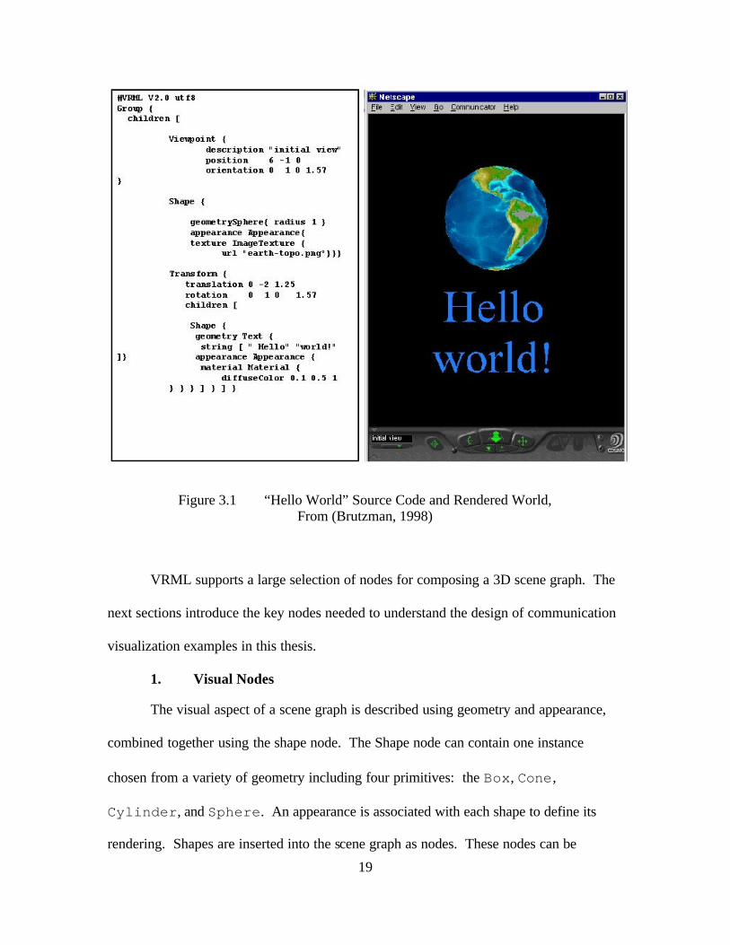
viewed with any VRML-capable Web browser. Figure 3.1 implements several of these
VRML nodes to create a virtual earth (Brutzman, 1998).
19
Figure 3.1 “Hello World” Source Code and Rendered World, From (Brutzman, 1998)
VRML supports a large selection of nodes for composing a 3D scene graph. The
next sections introduce the key nodes needed to understand the design of communication
visualization examples in this thesis.
1. Visual Nodes
The visual aspect of a scene graph is described using geometry and appearance,
combined together using the shape node. The Shape node can contain one instance
chosen from a variety of geometry including four primitives: the Box, Cone,
Cylinder, and Sphere. An appearance is associated with each shape to define its
rendering. Shapes are inserted into the scene graph as nodes. These nodes can be

20
grouped, sized, translated, rotated, colored, and textured to build more complex entities in
the virtual world. The shape node also contains several other nodes including
IndexedFaceSet, IndexedLineSet, IndexedPointSet, and
ElevationGrid. These nodes create arrays of polygons that map out an object in the
virtual world.
Figure 3.2 shows a Tropo Satellite Support Radio (TSSR) with beam antenna
pattern. A TSSR is a microwave radio set used for short-distance (less than 20 miles)
point-to-point communication. These complex shapes can be built using a combination
of primitive shapes.
Figure 3.2 Tropo Satellite Support Radio (TSSR) Built Using Primitive Shapes

21
Complex models are often built using specialized 3D authoring software or
Computer-Aided Design (CAD) software. With these software packages, a user can
convert and export the object to a VRML IndexedFaceSet node. The
IndexedFaceSet is used to create complex and realistic shapes in VRML. Once the
IndexedFaceSet is calculated, it is placed as a value in the geometric field of the
Shape node allowing it to be manipulated like primitive shapes.
Shape nodes also contain an Appearance node to allow the designer to specify
how an object is rendered. The Appearance node is used with the Texture and Material
nodes to specify texture images and color of the object. The Material node allows the
specification of diffuse, specular, and emissive color as well as shininess and
transparency. The Texture node allows images to be placed over an object for increased
realism. A terrain map or cartographic image can be placed over the elevation data in a
virtual world to present a more realistic or informative setting (Brutzman, 1998).
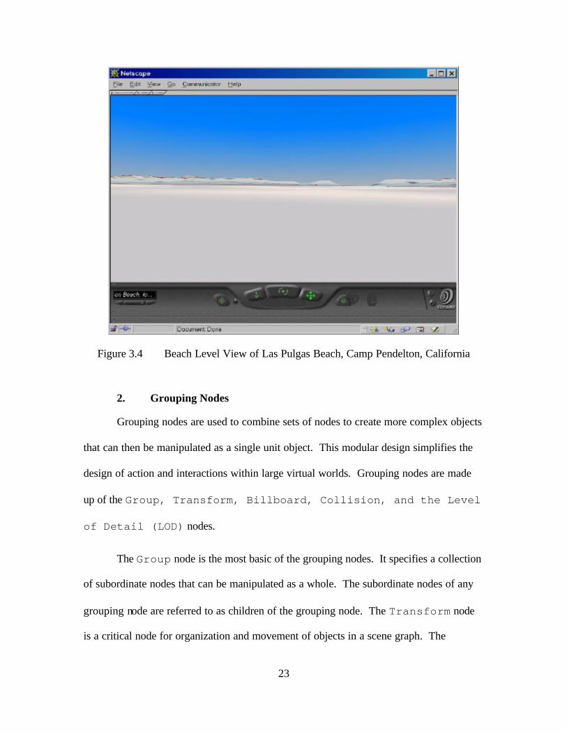
The terrain shown in Figures 3.3 and 3.4 was created using a feature within
MATLAB that reads DTED files and can generate values for VRML terrain files in the
form of an ElevationGrid (Brutzman and Blais, 2001). Figures 3.3 and 3.4 show
two views of the Las Pulgas Beach at Camp Pendelton, California. Figure 3.3 displays an
aerial view of the beach. The colors indicate the relative elevation of the beach. Figure
3.4 shows a ground level view from the beach.

22
Figure 3.3 Aerial View of Las Pulgas Beach at Camp Pendelton, California Generated from National Imaging and Mapping Agency (NIMA) Digital Terrain
Elevation Data (DTED) using a Matlab Script, After (Brutzman, Blais, 2001)
23
Figure 3.4 Beach Level View of Las Pulgas Beach, Camp Pendelton, California
2. Grouping Nodes
Grouping nodes are used to combine sets of nodes to create more complex objects
that can then be manipulated as a single unit object. This modular design simplifies the
design of action and interactions within large virtual worlds. Grouping nodes are made
up of the Group, Transform, Billboard, Collision, and the Level
of Detail (LOD) nodes.
The Group node is the most basic of the grouping nodes. It specifies a collection
of subordinate nodes that can be manipulated as a whole. The subordinate nodes of any
grouping node are referred to as children of the grouping node. The Transform node
is a critical node for organization and movement of objects in a scene graph. The

24
Transform node groups its subordinate nodes similar to the Group node, but it can also
bring groups of Group nodes together and move them within a local coordinate system.
Within the local coordinate system, the Transform node can also specify translational
rotational, and scaling changes of the children nodes. This is one of the fundamental
capabilities of a scene graph. The transform node can be combined with interpolator
nodes (defined below) to create animation in the virtual world. (Brutzman, 1998)
3. Viewing and NavigationInfo Nodes
The Viewpoint node is designed to make navigation easier within a virtual
world. It allows the designer to add predefined locations and camera angles for viewing
the scene. These predefined views, when carefully designed, can make navigation easier
within the virtual world by highlighting object or views the author feels are important.
These predefined views can be easily accessed through the navigation interface of the
VRML browser. Exploration of large virtual worlds is also more manageable because
viewers can jump to another location without needing to manually navigate through the
world. In Cosmo Software VRML Plug- in displays, shown in Figure 3.5, viewpoint
information is shown at the bottom left of the screen.

25
Viewpoint List
Zoom Navigation Controls Straighten
Undo Move Cosmo Information
Figure 3.5 Cosmo Software VRML Plug-In
The related NavigationInfo contains information about the physical
characteristics of the viewing avatar. These include the physical height, and speed at
which the avatar can move. The NavigationInfo node permits an author of a virtual
world to control how a view moves about the scene. A viewer may be forced or guided
to walk (rather than fly) though a scene (Brutzman, 1998). Further details and a 3D
tutorial for navigation in 3-space is provided by the Chomp! demo included in the Cosmo
Player distribution. Figure 3.6 shows the Chomp! demo.

26
Figure 3.6 Chomp Demo for 3-Space Navigation Practice (Silicon Graphics, 1998)
4. Behavior and Event Model
Nodes in VRML are defined by their fields and events. Fields contain values
representing the nodes. A behavior in VRML is a change in the field value. Events pass
behaviors with their timestamp to another field value. Script nodes can either be sinks
or sources of events. The VRML event execution model defines how VRML processes
events. After a sensor or script has generated an initial event, the event is propagated to
other affected nodes. These other nodes may respond by generating additional events,
continuing until all routes have been honored. This process is called an event cascade. All
events generated during a given event cascade are assigned the same timestamp as the
initial event, since all are considered to happen instantaneously. Once the event cascade
is complete, the results are rendered (Carey, 1997).

27
5. Interpolators Node and ROUTEs
After the scene graph has been designed with geometries and virtual objects, it is
often desirable to animate the scene. VRML uses interpolators and ROUTE nodes to
perform animation. Interpolator nodes are designed to provide keyframe animation,
where a position or rotation is specified for only a few, key fractional times. The VRML
interpolator nodes use these key fractional times and values as a rough sketch of the
animation and fill in the values between those specified as needed (Ames, 1997). The
most common interpolators are the position and orientation interpolators, but there are
also color, coordinate, normal, and scalar interpolators. The position and orientation
interpolators are used to create translated and rotational animation of objects in the scene
graph. Script nodes can extend the functionality of interpolators by allowing the
addition of software algorithms to control the interpolation.
Once the calculations are completed, the resultant values must be passed to
Transform, Shape, or Appearance nodes for the action to take place. ROUTEs
are used to dispatch events between VRML nodes. For example a ROUTE can take the
calculated changes from an interpolator and redirect the data into the Transform node.
The modified field in the Transform node implements the behavior changes in the
scene graph (Ames, 1997).
The TimeSensor node drives the animation process. The TimeSensor starts
and stops animation and control the animation speed. The TimeSensor node provides
the clock that the interpolators use to output positiona l data.

28
6. Sensor Nodes
There are six different sensors in the VRML specification that allow user
interaction within a scene graph. These are TimeSensor, TouchSensor,
VisibilitySensor, PlaneSensor, SphereSensor, and
CylinderSensor. Sensors are either triggered by time or user interaction.
TouchSensor, one of the primary sensors, activates whenever a mouse cursor or
pointing device is placed over or clicks on the sensed object. TouchSensors are
useful for turning on and off behaviors and linking to additional information. Script
nodes are also used to extend sensor functionality. New nodes being added in
X3D/VRML 200x include KeySensor and StringSensor for keyboard-based string
input.
7. Script Node
The VRML Script node is used to integrate imperative programming languages
such as Java and ECMAScript (formerly known as JavaScript) into the scene graph. The
Script node is used to connect programmed behaviors into a scene. Script nodes
typically signify a change or user action, receive events from other nodes, and contain a
program module that performs some computation, thereby effecting change somewhere
else in the scene by sending events. (VRML SPEC, 1997) The Script node can be
used with Interpolator and Sensor nodes to add flexibility and more complex
behaviors. It is often used to perform functions such as network access, physics
calculations, or a user-interface.
29
8. PROTO and EXTERNPROTO Definitions
The PROTO and EXTERNPROTO definitions are used to create new VRML nodes
as combinations of predefined VRML objects. PROTOs are especially useful for
constructing large, specialized scene graphs in which an object is used repetitively in
different ways or in many different worlds. Corresponding terms in X3D parlance are
ProtoDeclare, ProtoInstance, and ExternProtoDeclare. A PROTO
defining an object needs to be created only once, and then it can be instantiated wherever
the designer needs to use it. PROTOs provide an efficient way to create large virtual
worlds in modular fashion. EXTERNPROTOs can be placed in separate VRML files and
referenced in another scene by instantiating it in the local VRML file. Designers can
create libraries of complex objects for use in multiple worlds.
C. GEOVRML
The VRML97 specification is a powerful tool for representing 3D worlds. One of
its drawbacks is the ability for the specification to represent or utilize geographic
concepts. VRML97 does not address concepts such as latitude/longitude, related
coordinate systems, or the ability to navigate within these systems. GeoVRML 1.0
(www.geovrml.org) is a suite of nodes that define geo-referenced scene graph objects and
data such as maps and 3D terrain models. These nodes can also be viewed using a
standard VRML plug- in to a web browser. Resarchers at the Stanford Research Institute
(SRI) developed the GeoVRML suite of nodes and tools using software from the
Synthetic Environment Data Representation and Interchange Specification (SEDRIS)
(SEDRIS) project (SEDRIS, 2001). GeoVRML is now available to the public. The key

30
components of GeoVRML are ten specialized PROTO nodes designed for referencing
and interpolation of virtual worlds through geographic mechanisms. The GeoVRML
PROTOs use underlying Java code and Script nodes to perform the physically based
calculations and geographic modeling. The GeoVRML suite is a “Recommended
Practice” of the Web 3D Consortium (Iverson, 1999).
GeoVRML nodes perform similar functions to corresponding nodes in the
VRML97 specification. The left side of Figure 3.6 shows a GeoVRML code fragment
that builds the geo-referenced virtual scene shown on the right side of the figure. This
code does not display all of the declarations necessary for full geo-referencing, but it does
show the major nodes necessary to render a GeoVRML scene. This virtual Earth appears
similar to the virtual Earth in the original “Hello World” scene in Figure 3.1. The
original scene was a Sphere node wrapped in a texture map of the Earth.
The geo-referenced scene in Figure 3.6 is composed of elevation grids geo-
referenced to the actual latitude and longitude of the location. This scene demonstrates
the power of GeoVRML by placing an inverted cone at the exact location of Monterey
California. GeoVRML is a key technology for representing the virtual battlespace
because it will allow planners and operators to view actual areas using geographical
coordinate systems such as Latitude-Longitude and the Military Grid Reference System
(MGRS).

31
Figure 3.6 X3D Source Code and Rendering for GeoVRMLWorld.wrl, From (Murray, 2000)
GeoVRML allows the conversion of Digital Terrain Elevation Data (DTED) post
height information provided by the National Imaging and Mapping Agency (NIMA) into
correctly georeferenced maps for use in virtua l worlds. Military mission planning
requires this type of accuracy for terrain. GeoVRML supports the generation of
georeferenced terrain for 3D visualization of military plans at any location in the world.
GeoViewpoint {geoOrigin IS geoOrigingeoSystem ["UTM" ,"Z11"]position "3905500 578200 10000000“orientation 1 0 0 -1.57description "Welcome to Monterey“ }
#Build Earth w/ GeoElev. Grid & Lat/longShape {
appearance Appearance {material Material { diffuseColor 0.8 1.0 0.3 }texture DEF TEX ImageTexture
{ url "earth.gif" }}geometry GeoElevationGrid {
geoOrigin IS geoOrigingeoSystem [ "GDC" ]geoGridOrigin "-90 -180 0"xDimension 21zDimension 21xSpacing "18"zSpacing "9"height [0 0 0 0… (441 total) ]}}
GeoLocation {geoSystem [ "GDC" ] geoCoords "36.601388 -121.88166 200000"
#----------Lat/Long Monterey CAchildren [
Transform { rotation 1 0 0 3.1415926children [
Shape {appearance Appearance {material Material {
diffuseColor 1 0 0 }}geometry Cone {
bottomRadius 100000 height 500000 }
} ] } ] }

32
The next section introduces the major nodes available in GeoVRML. These
include GeoOrigin, GeoLocation, GeoPositionInterpolator, and
GeoViewpoint.
1. GeoOrigin
The currently supported coordinate reference systems in the GeoVRML suite
assume the virtual world begins at the center of the Earth. In order to gain optimal
precision of the model, GeoVRML provides the GeoOrigin node to specify the local
coordinate system. Only one GeoOrigin node is used within a scene, directing a
browser where to look inside the VRML world and to interpret the geological data.
(Reddy, 2000)
2. GeoLocation
The military uses maps for all types of planning and operational situations. It is
of critical importance to place objects at precise locations in a virtual battlespace. The
GeoLocation node provides the capability to place objects in a virtual world using a
geological reference frame. This node performs in a manner similar to the Transform
node of VRML97 specification. (Reddy, 2000)
3. GeoPositionInterpolator
In the VRML97 specification, the Transform node is coupled with the
PositionInterpolator node to provide smooth motion for animation. In the
GeoVRML suite, the GeoLocation node is also coupled with the
GeoPositionInterpolator. The GeoPositionInterpolator node
performs the function of keyframe animation by calculating key values and intermediate
position in geological coordinates. A time sensor is used to drive the process that passes

33
the coordinates to the GeoLocation node effecting movement of an object about a
geo-referenced world. (Reddy, 2000)
4. GeoViewpoint
The GeoViewpoint node performs the function of the viewpoint node in the
VRML97 specification. The GeoViewpoint node allows a designer to specify a
viewer’s location and orientation in a geo-referenced coordinate frame. The
GeoViewpoint node facilitates navigation within complex GeoVRML worlds.
D. EXTENSIBLE MARKUP LANGUAGE (XML)
Extensible Markup Language (XML) is a markup language defined by the World
Wide Web Consortium (W3C). XML is designed to allow the definition of structured
documents. XML is a subset of the Standard Generalized Markup Language (SGML).
SGML is an ISO standard that facilitates document formatting and processing. Its use
has expanded to encompass and facilitate all types of data exchange. XML is the
lightweight version of the full SGML implementation: design provides 80% of the
functionality (at 20% of the cost) of the full implementation of SGML (World Wide Web
Consortium (W3C), 2001).
XML allows the creation of elements or tagsets that describe data. This is
referred to as metadata, or data describing data. The data in such a document becomes
self-describing. XML uses entities as the basis for document definition. Each entity has
attributes defining the way it should be handled. XML provides a formal syntax for
describing the relationships between the entities, elements and attributes that make up an
XML document, which can be used to tell the computer how it can recognize the

34
component parts of each document (Bryan, 1997). The Document Type Definition
(DTD) formally defines the tagsets and relationships used in a document (World Wide
Web Consortium (WC3), 2000). The DTD ensures document validity by testing the
document conformance against the set of rules in the DTD. XML Schemas are similar
to DTDs. XML Schemas express shared vocabularies and allow machines to carry out
rules made by people. They provide a means for defining the structure, content and
semantics of XML documents (World Wide Web Consortium (W3C), 2000).
E. EXTENSIBLE 3D (X3D)
Extensible 3D (X3D) is the next-generation VRML specification. X3D is more
than an update to the VRML97 specification. X3D is a redesign of both the VRML97
code structure and encoding. X3D provides an Extensible Markup Language (XML)
encoding of the VRML97 specification. By using XML, the new X3D standard includes
a Document Type Definition (DTD) tag set that allows users to develop well- formed and
validated scene graphs. The extensibility of the XML encoding provides multiple
additional benefits. Extensibility gives X3D the ability to define and integrate new nodes
at runtime. X3D has the ability to encode geometries rapidly and also define new
geometries, which ensures correct the rendering of increasingly intricate models. X3D is
fully backward compatible with the VRML97 standard by providing identical
fundamental nodes and structures. X3D also provides an XML schema. The XML
Schema has been used to automatically generate an X3D Application Program Interface
(API), the Scene Authoring Interface (SAI) (Goldberg, 2001).

35
By using XML as the basis for X3D, designers now have the ability to create
geometries that contain XML metadata. Metadata is data describing the geometries in the
scene graph to other applications that may use the data. Metadata is especially powerful
for military planners because it provides definable geometries that can be transformed,
organized, and displayed according to their needs. Of particular interest are
corresponding metadata references for XHTML (W3C, 2000) and the XML-based
Resource Description Framework (RDF) (W3C, 2001).
The X3D-Edit authoring tool makes use of the X3D software suite to allow
developers to produce valid, syntactically correct scene graphs (Brutzman, 2001). X3D-
Edit employs and configures IBM’s Xeena XML editor (IBM Haifa Research Laboratory,
2000), which has been configured to facilitate the development of VRML scene graphs
conforming to the X3D Compact DTD. The tool uses an Extensible Stylesheet Language
(XSL) (Kay, 2000) to convert X3D documents to documents conforming to the VRML97
specification. After conversion, X3D-Edit automatically launches a VRML-enabled
browser for convenient debugging. Figure 3.7 shows a screen capture of X3D-Edit.

36
Figure 3.7 Screen capture of X3D-Edit Tool, From (Brutzman, 2000)
All modes in this thesis are generated using the X3D development environment.
Although the VRML97 specification is the basis for the models, X3D provides a
convenient structure and flexibility for producing valid scene graphs. Figure 3.8 show
examples of X3D and VRML code that will render identical worlds. These code sets
represent the Hello World scene shown in Figure 3.1.

37
Figure 3.8 VRML (left) and X3D (right) Source Code for "Hello World", From (Brutzman, 1999)
F. CHAPTER SUMMARY
XML, VRML, GeoVRML, and X3D are the underlying tools used throughout this
thesis to demonstrate exemplar 3D scenes. These powerful tools facilitate the creation
and displaying of 3D visualizations using common web browser technology. This
revolution will enable 3D graphics to become as commonplace as today’s 2D web page
technology.
#VRML V2.0 utf8Group {children [
Viewpoint {description "initial view"position 6 -1 0orientation 0 1 0 1.57 }
Shape {geometry Sphere { radius 1 }appearance Appearance{
texture ImageTexture {url "earth-topo.png"}}
}
Transform {translation 0 -2 1.25
rotation 0 1 0 1.57children [
Shape {geometry Text {string [" Hello” "world!" ]}
appearance Appearance {material Material {
diffuseColor 0.1 0.5 1 }}
}]
} ]
}
<X3D><Scene>
<Group > <Viewpoint
description='initial view‘orientation='0.0 1.0 0.0 1.57‘position='6.0 -1.0 0.0‘
/> <Shape>
<Sphere radius='1.0'/><Appearance>
<ImageTextureurl='"earth-topo.png" “
/> </Appearance>
</Shape><Transform
rotation='0.0 1.0 0.0 1.57'translation='0.0 -2.0 1.25'>
<Shape> <Text string='"Hello" "world!"'/><Appearance> <Material
diffuseColor='0.1 0.5 1.0‘/>
</Appearance> </Shape>
</Transform>
</Group> </Scene>
</X3D>

38
THIS PAGE INTENTIONALLY LEFT BLANK

39
IV. SCENARIO VISUALIZATION
A. INTRODUCTION
This chapter discusses the visualization aspects of a communication scenario.
The field of scientific and information visualization are introduced as well as the 3D
graphics palette available in VRML. The commonly used military communication
systems are presented based on the area of the electro-magnetic radio spectrum they
occupy. This section also discusses the aspects of visualizing each system.
B. VISUALIZATION
As computers become increasingly powerful, the amount of data generated also
increases. Computers and humans need to analyze the generated data in order to answer
the research questions for which they are tasked. The field of visualization is concerned
with presenting large datasets in meaningful ways for useful analysis. The two sections
below discuss both scientific visualization and its subcategory of information
visualization.
1. Scientific Visualization
Scientific visualization is the graphical presentation of scientific phenomena for
visual interpretation. The goal of scientific visualization is to enhance scientific
productivity by utilizing human visual perception and computer graphics techniques
(Domik, 1997). Most scientific visualization can be divided into one of two categories.
The first is the representation of scientific information for technical study. These
representations seek to provide a researcher with qualitative insights that might not be

40
seen without visualization. The key to this type of visualization is the accurate
representation of the underlying data.
A second goal of scientific visualization is to convey information to a
nontechnical audience. Such visualizations are different because they must provide
understanding a general audience that may not have insight into the observed phenomena.
The primary goals of this type of visualization are to provide clarity and user
understanding of the info rmation.
2. Information Visualization
Large datasets are sometimes difficult to analyze and understand using only
statistical methods. Information visualization is a subset of scientific visualization that
deals with the presentation of large data sets of (primarily numeric) information in a
graphical format. Information visualization seeks to map the data to a visualization
methodology system that provides viewers with increased understanding.
The graphical rendering primitives available to represent information include
lines, points, solids, images, semi transparent surfaces, and text. The attributes of the
information of interest can be represented by color, size, location, and the relative factors
of the information attributes. The common forms of information visualization include
bar or pie charts, graphs, maps, images, and 3D representations. Information
visualization is a recent and active field of research (Ware, 2000) (IEEE, 2001).

41
C. 3D GRAPHICS PALETTE
The 3D graphics palette consists of tools and techniques for use within 3D scenes
to convey information to the viewer. Some of the available tools include color and
textured appearance, size, distance, and animation.
1. Color and Textures
Color is a key tool in the visualization palette allowing a viewer to quickly
distinguish between similar objects or parts of the same object. In many applications,
data ranges are mapped to specific colors for visualization. The VRML color scheme is
based on RGB colors. The RGB color scale describes any color using numeric values
specifying the amount of Red, Green, and Blue. Intensities for each of these values are
based on a zero to one scale. The first value specifies the amount of red that is used, the
second green, and the third blue. A value of 1 means the color is shown completely. A
value of zero means that color is not used. For example, blue is (0 0 1) and bright yellow
is (1 1 0). VRML can also render glowing colors. These colors are also specified as in
the RGB format in the emissive field of a color node.
VRML further has the ability to map textures to shapes to present a more realistic
appearance. These textures can be images or movies. Textures are applied to objects
depending on the actual shape. A texture applied to a box will place the image on each
side of the box. A texture on a sphere wraps the image counter clockwise starting at the
back of the sphere. These considerations need to be taken into account when using
textures.
42
2. Size and Distance
The size of objects and distances between them are important parts of
visualization. Size, or relative size, should accurately reflect the visualized phenomena.
This prevents viewers from quickly dismissing the scenario as unrealistic. Visual cues or
references are needed to accurately judge size and distance in 3D.
3. Navigation
Large scenes or user worlds that are sparsely populated can be difficult to view.
The key to navigation is the ability to direct a viewer’s attention to an interesting part of
the scene. VRML provides Viewpoint nodes which allow an author to set specific
camera shots capturing important scenes within a world. VRML also provides the ability
for arbitrary user navigation in several modes including walking through, flying over, and
tilting or rotating the scene.
4. Animation
Animation is an effective way to convey information in 3D visualizations. To
prevent animations from appearing jittery, the visualization frame rate should be greater
than 10 frames per second. Until recently, this was only achievable on specialized
computer equipment optimized for graphics processing. In recent years, commodity PC
hardware can currently generate average frame rates of 6-10 frames per second for large,
complex scenes. It is expected that the rendering capabilities of commodity PCs will
continue to improve exponentially.
VRML utilizes keyframe processing for generating animation. All animations are
based on a relative time frame whose key ranges from 0 to 1. The position and rotation

43
of an object is specified per key, with the fractional times between 0 and 1. VRML then
calculates the intermediate values between these key values to give the animation a
smooth appearance. Overall time frames are then scaled to the actual length of the
animation.
D. RADIO COMMUNICATION
Radio communication is the generation and detection of electromagnetic waves
traveling through the air. Heinrich Hertz first demonstrated this ability in 1888. The
radio spectrum is a subset of the electromagnetic spectrum below infrared and visible
light. Radio waves are measured in length and frequency, which are inversely
proportional. Frequency measurements are in cycles per second or Hertz. The radio
spectrum extends from the Very Low Frequency (VLF) band beginning at 10 kilohertz
(kHz) to the top Extremely High Frequency (EHF) band at 300 gigahertz.
The military has communication systems in all bands of the frequency spectrum.
The visualizations described in this thesis concentrate on the Very, Ultra, and Super High
Frequency bands. Figure 4.1 and 4.2 show the frequency bands and military uses for
each.

44
VLF LF MF HF VHF UHF SHF EHF Infrared
| 100 kHz
| 1 MHz
| 10 MHz
| 100 MHz
| 1 GHz
| 10 GHz
| 100 GHz
Figure 4.1 Radio Spectrum Frequency Bands, After (Neuhaus, 2001)
Frequency Band Application
10 kHz to 30 kHz Very Low Frequency (VLF) Maritime Mobile Telephone Service
30 kHz to 300 kHz Low Frequency (LF) Radio Beacons for Aircraft Navigation
300 kHz to 3 MHz Medium Frequency (MF)
3 MHz to 30 MHz High Frequency (HF) Army Squad Radios
30 MHz to 144 MHz
144 MHz to 174 MHz
174 MHz to 328.6 MHz
Very High Frequency (VHF)
Mobile Radio Communication
328.6 MHz to 450 MHz
450 MHz to 470 MHz
470 MHz to 806 MHz
806 MHz to 960 MHz
960 MHz to 2.3 GHz
2.3 GHz to 2.9 GHz
Ultra High Frequency (UHF)
Trucked or Conventional Base Radio
Ground to Aircraft Radio
Greatest Usage between 806 MHz to 906 MHz
Wireless Communication Service
2.9 GHz to 30 GHz Super High Frequency (SHF) High Capacity Network Transmission
30 GHz and above Extremely High Frequency (EHF) Point-to-Point Microwave Service Table 4.1 Frequency Ranges and Usage of the Radio Spectrum in the United States,
After (Laflam, 2000)
45
E. SCENARIO VISUALIZATION
This section describes tactical communication visualization from a scene and
scenario point of view. It examines the different types of tactical communications radio
systems that will be represented. It primarily looks at systems based on the frequency
band they occupy. The Very High Frequency (VHF), Ultra High Frequency (UHF), and
Super High Frequency (SHF) are examined. Additionally, satellite systems throughout
the radio spectrum will be examined for special visualization requirements.
1. Very High Frequency (VHF) Communication Systems
The Very High Frequency band exists in the 30 to 300 megahertz (MHz) range of
the radio spectrum with wavelengths between 1 and 10 meters. The typical military
communications systems operate at the lower end of the VHF band. This typically
increases the maximum range of the transmissions. VHF systems are commonly used in
mobility requirements because they can provide omni directional area coverage.
Two common VHF systems are the AN/MRC-145 and the AN/PRC-119. The
MRC-145 is a vehicle mounted VHF- Frequency Modulated (FM) radio that operates
between 30 and 87.975 MHz. The MRC-145 provides long-range communications of up
to 21 miles using an omni-directional antenna. The typical data rate is between 600 and
4800 bits per second (bps). The PRC-119 is a man-portable radio used in the same
operating frequencies. It has a range of 5 miles also with a data rate of 600 to 4800 kbps.
VHF system visualization represents unique requirements because of the large
omni-directional coverage areas. Physical and man-made objects, such as terrain features
and large buildings, can also obstruct VHF signals. Vehicles having multiple radios or

46
densely populated troop areas can quickly increase the scenarios complexity. The use of
many overlapping coverage areas can quickly make UHF signals indistinguishable.
2. Ultra High Frequency (UHF) Communication Systems
The Ultra High Frequency band exists in the 300 MHz to 3-gigahertz (GHz) range
of the radio spectrum with wavelengths between 0.1 and 1 meter. The typical military
communications systems operate at the upper end of the VHF band and into the lower
end of the UHF band. The frequencies between 225.0 and 399.975 MHz are used
predominantly for air-to-ground communications, but can also be used for local ground-
to-ground communications also. The range for military air-to-ground systems in the
UHF band is 200 miles while the ground-to-ground is up to approximately 35 miles
where there are minimal (or no) obstructions between communication points.
UHF signal visualization has similar challenges to those dealt with in VHF
visualization. The UHF ground-to-ground communication applications also require large
coverage areas with the possibility of many users within a small footprint. The air-to-
ground signals also provide a challenge in their extremely large operational ranges.
There are typically only a few personnel that would be in contact with aircraft using
ground-to-air communications.
3. Super High Frequency (SHF) Communication Systems
The Super High Frequency band exists in the 3 GHz to 30 GHz range of the radio
spectrum with wavelengths between 0.01 and 0.1 meter. The military employs SHF
communications for high bandwidth, point-to-point applications. SHF systems are
operated in line of sight, obstacle gain defraction, or troposcatter modes. LOS operation
requires an unimpeded path between transmitter and receiver and is used for links up to
47
25-30 miles. Obstacle gain defraction is used for longer distances of up to 60 miles.
Both transmitters aim at the highest point of the LOS obstruction and use the refractive
properties of SHF energy to bend the beams to the distant end’s receiver. The
troposcatter method is used for longer link requirements of up to 100 miles. Both end
points aim at predetermined points on the troposphere and use the refractive energy of
SHF to bounce their signals off the troposphere.
The AN/TRC-170 tropospheric scatter radio set and the TER-170 Tropo Satellite
Support Radio (TSSR) both operate within the SHF band. The TRC-170 utilizes either
LOS or tropo communication modes. It can transmit up to 4608 Kbps and operates in the
4.4 to 5.0 GHz range with a bandwidth of 3.5 or 7 MHz. The Tropo Satellite Support
Radio (TSSR) is a full-duplex, line-of-sight microwave radio terminal used for short-
range point-to-point military applications. The TSSRs are used to remote equipment or
personnel by replacing long cable runs. The TSSR operating range is 20 miles. It can
transmit up to 6144 Kbps and operates in the 14.4 to 15.35 GHz range.
The primary aspect of the SHF system visualization is how to show point-to-point
connectivity over long distances. The visualization must also take into account the three
different modes of operation possible with SHF. Realistic tropospheric scatter and
refractivity visualization can be particularly challenging.
4. Satellite Systems
Tactical military satellite systems exist across the entire radio-frequency
spectrum. Communication satellites are usually in a geosynchronous orbit.
Geosynchronous satellites orbit the earth at a precise altitude above the earth allowing the
speed of the satellite to equal the speed of the earth’s rotation. This enables the satellite

48
to appear stationary from the earth. The geosynchronous satellite coverage area is nearly
one half of the earth’s surface. From a tactical perspective, the visualization of this
footprint is irrelevant because all battlefield operations are typically visible to a single
satellite. It is still useful to show users communicating through the satellite, and to also
the ultimate end points for the communication link.
F. CHAPTER SUMMARY
The field of information visualization provides useful insights into the tactical
communication visualization problem. It is necessary to represent the communications
systems so users can understand and act on the increased information presented. One
way to analyze the communication scenario is to examine each communication frequency
bands. Each band presents has unique characteristics which must be taken into account
to create accurate visualizations.

49
V. SHARED VISUALIZATION OF RADIO CHARACTERISTICS USING DISTRIBUTED INTERACTIVE SIMULATION (DIS)
A. INTRODUCTION
This chapter examines the Distributed Interactive Simulation (DIS) protocol and
how communication entities using DIS can be visualized. The first section introduces
the DIS PDU categories. Next, the radio communication family of PDUs is discussed, as
well as the individual parameters contained within them and how these parameters can be
visualized. The final section describes the DIS-Java-VRML software toolkit.
B. DISTRIBUTED INTERACTIVE SIMULATION (DIS) PROTOCOL DATA UNIT (PDU) CATEGORIES
The DIS standard specifies a set of messages or Protocol Data Units (PDUs) that
contain ordered data fields conveying state information about the entities in the
simulation. The DIS standard defines 27 different PDUs, which can be grouped into 6
categories. The categories will be examined in more detail below.
1. Entity Information/Interaction PDUs
The Entity State and Collision PDUs represent the entity information interaction
category. The Entity State PDU communicates information about an entity’s current
physical state. State data includes location, velocity, orientation, appearance, markings,
and position and movement of articulated parts. The Entity State PDU also indicates the
entity sending the PDU and the team or force to which the entity belongs. The Collision
PDU is used to convey information about collisions between two simulated entities, or
else collision between an entity and an object existing in the virtual environment.

50
DIS applications typically have each entity calculate the current position for all
entities based on previous state information. This “dead reckoning” of location
parameters facilitates the variable PDU packet-transmission scheme used within DIS.
This significantly reduces the amount of PDU traffic required to be sent. The Entity State
PDU may also be sent periodically to indicate a heartbeat update, or to offset any lost
PDUs.
2. Warfare PDUs
The warfare category represents the use of weapons and effects in the virtual
battlespace. It consists of Fire and Detonation PDUs. The Fire PDU communicates
information regarding the firing of a weapon. The Detonation PDU contains information
about the impact or detonation of a weapon. These are used in conjunction to determine
the effects of a weapon on other entities in the environment.
3. Logistics PDUs
DIS simulations use a series of PDUs to represent logistics functions. These
include Service Request, Resupply Offer, Resupply Received, Resupply Cancel, Repair
Complete, and Repair Response PDUs. The logistics activities are controlled through a
series of request and response messages between entities.
4. Simulation Management PDUs
There are numerous PDUs in the simulation management category including
Start/Resume, Create Entity, and Remove Entity. There are two types of management
PDUs. They are entity/exercise control and data. The simulation protocol may or may
not be used depending on the exercise.
51
5. Distributed Emission Regeneration PDUs
The Distributed Emission Regeneration category consists of the Electromagnetic
Emission and Designator PDU. The Electromagnetic Emission PDU is used to
communicate information regarding active electromagnetic emissions, including active
countermeasures. The Designator PDU is a functional designator for such activities as
lasing a target to support a laser-guided weapon.
6. Radio Communications PDUs
The radio communications family of PDUs contains a transmitter, receiver, and
signal PDUs. The Radio Communication Protocol (RCP) communicate information
about both audio and data transmission via radio and Tactical Data Links. The RCP also
supports actual transmission of information in real- time, or conveyed through a pre-
recorded database. The visualizations within this thesis are based on data fields within
the transmitter, signal, and receiver PDUs to ensure compatibility with the underlying
simulation protocol.
C. RADIO COMMUNICATION FAMILY PROTOCOL DATA UNITS
The radio communication family of Protocol Data Units consists of 3 PDUs:
transmitter, receiver, and signal. They are used to represent radio objects within
simulations. Each of the PDUs and their individual parameters will be discussed. The
three PDUs have two common fields. The first is Entity ID and the second is Radio ID.
The Entity ID is used to uniquely designate any Entity during a specific exercise. An
entity could be a tank, plane, military unit, or any other object that can be simulated. The
Radio ID is used to identify a specific radio within the simulation.

52
There are two types of values within the Radio Communications Family PDUs.
The first are parameters with enumerated values, which have only a certain number of
specific values that can be used. The antenna pattern type parameter is a simple example
of the enumerated field. It can have three different values: beam, omni-directional
dome, or spherical harmonic. The second type of parameter is a numerical value, which
can take any value within the specified range. Frequency is an example of a numerical
parameter. It can take any numerical value between zero and its maximum allocated byte
size.
1. Transmitter PDU
The transmitter PDU contains all the information needed to specifically identify a
radio transmitter within a simulation. The information contained within each PDU can be
used to calculate additional parameters such as signal strength, coverage area, and other
fields needed to represent transmitted signals. There are a large number of parameters
used within the transmitter PDU. This section describes the parameters contained within
the transmitter PDU (IEEE, 1995):
§ PDU Header. This field shall contain data common to all DIS PDUs. § Entity ID. This field shall identify the entity that is the source of the radio
transmission. § Radio ID. This field shall identify a particular radio within a given entity.
Radio IDs shall be assigned sequentially to the radios within an entity, starting with Radio ID 1. The combination of Entity ID and Radio ID uniquely identify a radio within a simulation exercise.
§ Radio Entity Type. This field shall indicate the type of radio being simulated.
§ Transmit State. This field shall specify whether a radio is off, powered but not transmitting, or powered and transmitting.
§ Input Source. This field shall specify which position, (pilot, co-pilot, first officer, gunnery officer, etc.) or data port in the entity utilizing the radio, is providing the input audio or data being transmitted.
§ Antenna Location. This field shall specify the location of the radiating portion of the antenna.

53
§ Antenna Pattern Type. This field shall specify the type of representation used for the radiation pattern from the antenna.
§ Antenna Pattern Length. This field shall specify the length in octets of the Antenna Pattern Parameters field.
§ Frequency. This field shall specify the center frequency being used by the radio for transmission. This frequency shall be expressed in units of hertz.
§ Transmit Frequency Bandwidth. This field shall identify the bandpass of the radio defined by the Radio ID field and the Radio Type field.
§ Power. This field shall specify the average power being transmitted in units of decibel-milliwatts.
§ Modulation Type. This field shall specify the type of modulation used for radio transmission.
§ Crypto System. This field shall identify the crypto equipment utilized if such equipment is used with the Transmitter PDU.
§ Crypto Key ID. This field shall consist of 16 bits. The high-order bit, when cleared, shall indicate that the crypto equipment is in the baseband encryption mode, and when set shall indicate that the crypto equipment is in the diphase encryption mode.
§ Length of Modulation Parameters. These fields shall specify the length in octets of the modulation parameters.
2. Receiver PDU
The receiver PDU contains all the information needed to specifically identify a
radio receiver within a simulation. Each receiver PDU contains information about the
entity receiver and can be used to calculate whether a signal was received and if a link
could be established. This section describes the parameters contained within the receiver
PDU (IEEE, 1995).
§ PDU Header. This field shall contain data common to all DIS PDUs. § Entity ID. This field shall identify the entity that is controlling the radio
transmission. The source entity may either represent the radio itself or represent an entity (such as a vehicle) that contains the radio.
§ Radio ID. This field shall identify a particular radio within a given entity. Radio IDs shall be assigned sequentially to the radios within an entity, starting with Radio ID 1. The combination of Entity ID and Radio ID uniquely identifies a radio within a simulation exercise.
§ Receiver State. This field shall indicate the state of the receiver, which shall either be idle or active.
§ Received Power. This field shall indicate the radio frequency power received, after applying any propagation loss and antenna gain.

54
§ Transmitter Entity ID. This field shall identify the entity that is the source of the transmission that is currently being received.
§ Transmitter Radio ID. This field shall identify the particular radio within the entity cited in Transmitter Entity ID that is the source of the radio transmission.
3. Signal PDU
The signal PDU contains the information being sent between transmitter and
receiver. These packets contain the actual voice, video, or data emissions being sent by
the transmitter. This section describes the parameters contained within the signal PDU
(IEEE, 1995).
§ PDU Header. This field shall contain data common to all DIS PDUs. § Entity ID. This field shall identify the entity that is the source of the radio
transmission. The source entity may either represent the radio itself or represent an entity (such as a vehicle) that contains the radio.
§ Radio ID. This field shall identify a particular radio within a given entity. The Entity ID, Radio ID pair associates each Signal PDU with the preceding Transmitter PDU that contains the same Entity ID, Radio ID pair. The combination of Entity ID and Radio ID uniquely identifies a particular radio within a simulation exercise.
§ Encoding Scheme. This field shall specify the encoding used in the Data field of this PDU.
§ TDL Type. This field shall specify the TDL Type as a 16-bit enumeration field when the encoding class is the raw binary, audio, application-specific, or database index representation of a TDL message. When the Data field is not representing a TDL Message, this field shall be set to zero.
§ Sample Rate. This field shall specify either the sample rate in samples per second if the encoding class is encoded audio or, the data rate in bits per second for data transmissions. If the encoding class is database index, this field shall be zero.
§ Data Length. This field shall specify the number of bits of digital voice audio or digital data being sent in this Signal PDU.
§ Samples. This field shall specify the number of samples in this PDU. § Data. This field shall specify the audio or digital data conveyed by the
radio transmission. The interpretation of the Data field depends on the value of the encoding scheme and TDL Type fields.

55
D. PDU VISUALIZATION
The section will discuss the use of the PDU parameters to generate 3D
visualizations of communication entities. The Radio Entity Type contained within both
the transmitter and receiver PDUs will not be visibly displayed, but will be used for
calculations relating to the coverage areas, frequency, power, and signal propagation
distances.
Transmitter frequency is a key parameter within the Transmitter PDUs. Different
colors or texture patterns denote different frequency emissions. This allows an operator
to easily identify frequency conflicts or problems that could impair necessary information
passing. The transmitter power parameter coupled with the Radio Entity Type enables
scaling of the antenna patters such as transmitter domes or transmission propagation
distances to reflect realistic values.
The Antenna Pattern Type contains three enumerated fields and describes the type
of coverage an emitter will generate. The three are omnidirectional, beam, and
spherical-harmonic. The beam pattern is further broken down to give more
information about the directional beam. These subcategories include the beam direction,
azimuth beamwidth, and elevation beamwidth. The azimuth and elevation beamwidth
specify the –3 dB (half-power) power-density point in the X-Y plane and X-Z plane,
respectively.
The Transmit State parameter enumerates the status of the transmitter: off, on
but not transmitting, or on and transmitting. The antenna is shown
without additional information to indicate an off state. This field is visualized with
56
visible domes when the transmitter is on. A lightning-bolt pattern indicates when a radio
is transmitting and will show the packet path to an acknowledged receiver.
Once a receiver determines it can successfully receive PDUs from the
broadcasting transmitter, the receiver renders a line from itself to the transmitter. This
allows users to easily see the network connectivity between transmitting and receiving
entities. Note that only receivers render connecting lines, in order to provide a scalable
and nonrepetitive way of displaying connectivity information.
The Receiver State parameter is similar to that of the Transmitter State parameter
in the Transmitter PDU. The Receiver State enumeration can take the following values:
off, on but not receiving, or on and receiving. The representations
are similar. A receiver in the off state is shown as a stand-alone antenna. The receiver
that is on, but not receiving signals will have a small dome shown over it.
While it is receiving a signal, the dome is increased in size to indicate receipt of a
parameter of interest. If the received signal is above the minimum signal strength, a
connection is shown between the receiver and the transmitter. In this way, the viewer can
then determine whether a signal is being received, but is not strong enough to close the
link or is it is not being received at all.
E. DIS-JAVA-VRML
DIS-Java-VRML is an open source software toolkit and library of applications
that enables VRML / X3D scenes to be DIS compliant through the use of Java
networking code (Brutzman, 2001). DIS-Java-VRML is designed to provide DIS
connectivity using the functionality of the Java programming language in standalone

57
mode or compatibly with the 3D modeling and visualization of VRML. It provides a
scene developer with a set of libraries and examples with which they can develop
networked 3D virtual worlds. The goal of the DIS-Java-VRML working group’s goal
was not to invent a new protocol design, but instead to develop Java class libraries and an
architecture for exchanging DIS packets over a Local-Area Network (LAN) or the
Internet.
The combination of VRML script nodes and the Java classes passing information
through the event in and event out fields allows information to be updated in a VRML
scene graph. Such network connectivity between 3D virtual worlds makes this
environment useful as a collaborative planning system. Multiple users can now design
scenes and interact within a world even though they may be geographically separated.
The toolkit also facilitates the development of a 3D virtual battlespace containing many
entities controlled at different locations.
DIS, Java, and VRML can provide all of the pertinent capabilities needed to implement large-scale virtual environments (LSVEs). DIS is essentially a behavior protocol tuned for physics-based (i.e. “real world”) many-to-many interactions. Java is the programming language used to implement the DIS protocol, perform math calculations, communicate with the network and communicate with the VRML scene. VRML 3D graphics are used to model and render both local and remote entities in shared virtual worlds. (Brutzman, 2000 website)
Examples are examined further in the following chapters. DIS-Java-VRML
development software and models are available at
(http://www.web3d.org.WorkingGroups/vrtp/dis-java-vrml).

58
F CHAPTER SUMMARY
The visualization of communication signals is addressed in a two level approach.
First, the available information must be examined for relevance and suitability for
visualization. Second, an overview of the communication space and tactical battlefield is
needed to ensure accurate and effective representation. This two-phase approach will
help ensure maximum usability for planners and operators.

59
VI. OPERATIONS AND COMMUNICATIONS PLANNING
A. INTRODUCTION
Operational planning is accomplished throughout the military chain of command.
It is directed by the National Command Authorities and accomplished by the Combatant
Commanders and their subordinate levels of command. Operational planning takes place
at strategic, operational, and tactical levels of war. This planning has a cascading effect
in which the generated operation plan becomes the basis for subordinate planning and the
generation of next level of orders. This chapter will provide an overview of military
operations planning and orders, focusing on communication annexes.
B. OPERATIONS PLANNING
Military planning is accomplished at all echelons of command and across the full
range of operations in which the military is involved. Military planning typically falls
into one of two categories. The first is force planning, which is mostly handled by the
individual services that are charged with the training, equipping, and providing force to
the Combatant Commanders. The second is operations planning, summarized in this
section. Operations planning is directed toward the employment of military forces within
the context of a military strategy to attain specified objectives for possible contingencies
(Joint Pub 5-0, 1995). Operations planning is used to created operation plans
(OPLANs) and operation orders (OPORDs) for all levels of wartime and peacetime
operations.

60
1. Strategic Level
Operational planning at the strategic level of war consists of translating the
country’s broad national security objects into strategic military objectives. This planning
is accomplished between the NCA, Combatant Commanders, and the Joint Chiefs of
Staff. The plans are realized as theater- level strategies employed by each of the regional
Commanders In Chief.
2. Operational Level
Operation planning at the operational level links the tactical employment of forces
to strategic objectives (Joint Pub 5-0, 1995). The objective of operational- level planning
is to attain specific goals through campaigns or operations. This planning seeks to
determine when, where, and how major force employment will take place.
3. Tactical Level
Tactical operation planning is the employment and maneuver of military units
against the enemy. Tactical plans bring maximum combat force to bear against enemy
units. This level of planning is concerned with engagements and battles. The signal
planner is primarily concerned about the tactical employment of forces at this level.
C. OPERATION ORDER (OPORD)
An Operation order (OPORDs) is a specifically formatted message that outlines
actions subordinate units are to take. It is directive in nature. The header of the message
contains transmission information showing the sender and all recipients of the message.
The next section contains the task information and all of the forces that are required for
execution. The beginning text contains information about the message such as when it
was sent, the classification, and other administrative details.

61
The next section contains information about the overall situation, as it is currently
assessed. It contains information about both friendly and enemy forces. Next, the full
mission statement for the operation is given. The next section consists of the execution
information. This section gives the overall concept of operations so all tasked units can
understand their role in the bigger operation. The execution information also outlines the
task assignments and gives the coordinating instructions. The last section contains
administrative and logistics information. This section also contains the information about
the command, control, and communications (C3) procedures and systems to be used. If a
large operation is being planned, C3 information is contained in an OPORD annex
containing appropriate references to the main OPORD.
The OPORD structure is part of the United States Message Text Format
(USMTF) (DISA, 2001). The Defense Information Systems Agency (DISA) maintains
this text only message-formatting standard. The USMTF was designed to enhance joint
and coalition warfighting effectiveness through the standardization of message formats,
data elements, and information exchange procedures (Chairman Joint Chiefs of Staff
Instruction 6241.01, 1996). USMTF has been in use within the DoD for many years.
Recently, there has been interest in migrating from a text-only solution to an
Extensible Markup Language (XML)-based solution. This initiative is known as the
Extensible Markup Language Message Text Format (XML-MTF). The XML-MTF has
four significant benefits over USMTF. First, USMTF is a 30-year-old technology that
exists as a government standard thus limiting software acquisition and upgrade choices.
Second, the USMTF is tied to the 1960s-era Teletypeprinter, which limits the way data
can be presented in messages. Third, the USMTF is only able to send the information

62
that is part of the actual message. It does not allow metadata (information about the
information) to be transmitted. Lastly, XML will provide a significant improvement in
the way in which messages can be syntactically checked and then used for higher-level
information exchange. This facilitates computer-to-computer data processing and
advanced autogeneration of visualizations as shown in the thesis “Automatically
Generating A Distributed 3D Battlespace Using USMTF and XML-MTF Air Tasking
Order, Extensible Markup Language (XML) and Virtual Reality Modeling Language
(VRML)” (Murray-Quigley, 2000). XML-MTF work is ongoing (XML-MTF
Development Team, 2001).
D. RADIO COMMUNICATION PLANNING
Communication planning is one part of the larger Command, Control,
Communication, and Computer (C4) planning that a signal planner must complete.
Similar to operation planning, it also exists across all echelons of the military. C4
planning consists of information assurance, satellite communication, frequency spectrum,
and command and control planning. This section focuses on the tactical communication
planning dealing with radio communications.
Communication planning is completed in conjunction with the operation planning
ensuring support to the overall operation. Communication planning begins once a signal
planner receives initial guidance on the supported units’ operation plan and preliminary
request for communications support. Signal planners use a variety of tools to create a
communication plan.

63
Signal planners utilize planning tools like Mobile Subscriber Equipment –
Network Planning Terminal (MSE-NPT) and System Planning, Engineering and
Evaluation Device (SPEED) to develop tactical radio link plans. These tools use Digital
Terrain Elevation Data (DTED) to determine suitable locations for antennas. They also
calculate coverage areas for mobile systems.
Figure 5.1 shows the SPEED Radio Coverage Analysis Tool. This tool uses the
underlying topographic information to show predicted coverage area for the center radio.
As depicted, the other two radios should be able to communicate with the center radio.
SPEED contains most of the common military radios so that a user can quickly input a
scenario and obtain appropriate results. The inset picture in the upper left hand corner of
Figure 5.1 shows the surrounding area of the main scene for context.
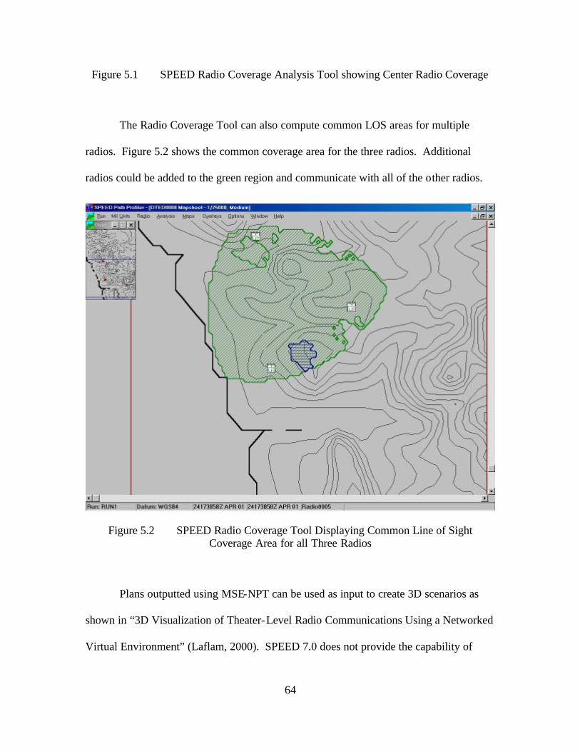
64
Figure 5.1 SPEED Radio Coverage Analysis Tool showing Center Radio Coverage
The Radio Coverage Tool can also compute common LOS areas for multiple
radios. Figure 5.2 shows the common coverage area for the three radios. Additional
radios could be added to the green region and communicate with all of the other radios.
Figure 5.2 SPEED Radio Coverage Tool Displaying Common Line of Sight Coverage Area for all Three Radios
Plans outputted using MSE-NPT can be used as input to create 3D scenarios as
shown in “3D Visualization of Theater-Level Radio Communications Using a Networked
Virtual Environment” (Laflam, 2000). SPEED 7.0 does not provide the capability of

65
generating output files. SPEED 8.0 will be released in summer 2001. Once released, it
should be evaluated for the possibility of linking it with a 3D rendering software package.
E. ANNEX K - COMMAND, CONTROL, COMMUNICATION, AND COMPUTER (C4) SYSTEMS
The Annex K or Command, Control, Communication, and Computer (C4) System
Annex contains communication section of an OPORD. This allows the document to be
created and transmitted independently from the rest of the OPORD document. The
format for the body of the Annex K follows the same format as the ORORD. It gives an
overview of the situation and assigns tasks to subordinate units. There may be additional
appendixes containing information about the information assurance plan, overall C4 plan,
satellite communications plan, defense courier service information, and the frequency
spectrum plan. In a multi-national operation, an appendix with foreign data exchange
requirements may also be included.
F. CHAPTER SUMMARY
Military operations are complex events with many participants. Military
operation planning must be completed correctly to synchronize actions of everyone
involved. Operation planning exists on a continuum across all levels of war from
strategic to operational to tactical. It also exists within each echelon of command. The
OPORD provides each unit its assigned role and mission within the overall operation.
The signal planner is concerned with the mission and specifically the C3 requirements
outlined in the OPORD.

66
THIS PAGE INTENTIONALLY LEFT BLANK

67
VII. MODELING COMMUNICATIONS PLANNING AND OPERATIONS USING THE NATO LAND C2 INFORMATION
EXCHANCE DATA MODEL (LC2IEDM)
A. INTRODUCTION
Future warfare will increasingly rely on ad hoc coalition environments with
disparate communication and information technology systems. These systems must be
able to interoperate and exchange data. All Coalition partners must agree upon standards
prior to the start of operations. NATO is currently evaluating the Land C2 Information
Exchange Model (LC2IEDM), as part of a bigger Generic Hub (GH) data model, for data
exchange suitability. The US Navy’s Naval Undersea Warfare Command (NUWC) and
the Institute for Defense Analysis (IDA) are extending this primarily land-focused model
to incorporate Naval representations. This chapter briefly introduces the data model and
evaluates its suitability for representing communications planning and operations.
B. DATA INTERCHANGE
As the Department of Defense (DoD) progresses along the knowledge pyramid
from data to knowledge it is trying to attain increasingly higher levels of understanding.
This understanding is facilitated by interconnected systems. These systems need
structured formats for passing information. This structured methodology allows systems
to pass specific information and rely on the other system to represent it correctly. A
command and control example is an Air Force system passing a structured message
‘Squadron of F-16s at the air base’ and having an Army system represent it correctly.

68
Systems use data models to provide such format and message structure. By
outlining a format and structure, the data model provides the basis for these systems to be
able to pass data the other system can understand. This information exchange model
does not specify the way data must be represented or stored on a specific system. It only
specifies what and how information must be exchanged between different systems. This
significantly reduces the number of things that must be specified and gives system
implementers freedom to extend the specifications to meet their needs.
The NATO C3 Technical Architecture (NC3TA) Interoperability Reference
Model describes four levels for classifying a system’s interoperability. They are:
Degree 1: Unstructured Data Exchange. Involves the exchange of human-interpretable unstructured data such as the free text found in operational estimates, analysis and papers.
Degree 2: Structured Data Exchange. Involves the exchange of human-interpretable structured data intended for manual and/or automated handling, but requires manual compilation, receipt and/or message dispatch.
Degree 3: Seamless Sharing of Data. Involves the automated sharing of data amongst systems based on a common exchange model.
Degree 4: Seamless Sharing of Information. An extension of degree 3 to the universal interpretation of information through data processing based on co-operating applications (NC3TA, 2000).
The proposed NATO Generic Hub Data Model is a proposal to create a Degree 3
specification for seamless sharing of data. By adhering to the model, it will also facilitate
users creating systems that can seamlessly share information.

69
C. GENERIC HUB
NATO’s automated information exchange plan requires a structured
representation of information that needs to be exchanged. This representation must be
specific enough to be meaningful, but also flexible enough so that it can change over time
to represent new information needs. The model should serve as a hub for countries
seeking to base new information systems on it. The NATO Generic Hub data model was
designed to meet these needs.
The primary goal of the Generic Hub model is an information exchange data
model. The model will provide the basis for structured information exchange not
currently available with messaging systems. As a minimum, the NATO nations wish to
have the GH Data Model preserve the meaning and relationships of the information
exchanged and thereby attain the interoperability associated with NATO Level 4 of
System Interconnection (automated exchange of data, with user- imposed constraints,
between C2IS databases) (NATO, 2000).
The Generic Hub Data Model uses land combat operations as the generic
battlespace hub for model. Functional areas of the battlespace can be viewed as spokes
originating in the hub and extending outward as shown in Figure 6.1. The functional
areas include Fire Support, Air Support, Administration, Communications and
Electronics, Intelligence/Electronic Warfare, etc. There are some common
representations between the functional areas and the generic battlespace hub. This
ensures data consistency across the model.

70
Air Support
Fire Support
Special Ops
Combat ServiceSupport & Logistics
Intelligence/Electronic Warfare(IEW )
Air Defense &Airspace Control
EngineerOperations
Land CombatOperations
Communicationsand Electronics
Administration(Personnel)
Figure 6.1 Generic Hub and Its Relationship to Subfunctional Areas, From (NATO, 2000)
D. LAND C2 INFORMATION EXCHANGE DATA MODEL (LC2IEDM)
The Land C2 Information Exchange Data Model (LC2IEDM) is the base of the
generic hub. The structure is meant to be generic and include all land, sea, and air
operations although it currently focuses primarily on the land portion. It seeks to define
the information that is relevant to the generic battlespace and also the information that
has meaning within several of the functional areas. The model describes objects of
interest including forces, personnel, weather, terrain features, and organizations. The
data model also includes information about the relationship between objects. An
individual airman who belongs to the 51st Fighter Wing at Osan AB, Korea is an example
of specific information that can be represented.
The data model has five key independent entities. They include OBJECT-ITEM,
OBJECT-TYPE, CAPABILITY, LOCATION, and ACTION. OBJECT-ITEM entity is
an individual object that has some significance. An example is a specific person such as

71
a commander. The OBJECT-TYPE entity is a class of objects with significance. This
could be a type of facility such as an airfield or a type of person such as a specific rank or
position. The CAPABILITY entity provides the ability to perform a mission or function.
LOCATION entity is a position within a specific frame of reference. ACTION entity is
an activity or how that activity may take place. This would include operational plans and
logistic requests and activities.
The five secondary entities include CANDIDATE-TARGET-LIST, CONTEXT,
REFERENCE, REPORTING-DATA, and RULE-OF-ENGAGEMENT. The use of these
10 independent entities and the relationships between them allow for the full specification
of a battlespace situation that can be transmitted between systems to convey information.
E. THE COMMUNICATIONS-ELECTRONICS EXTENSION FOR MODELING COMMUNICATION PLANNING AND OPERATIONS
The Communications-Electronics (CE) extension describes all facets of
communication and information areas in the battlespace including design, development,
installation, operation, and maintenance of systems dealing with collecting, transmitting,
processing, and displaying of data and information. The scope of the CE extension is
limited to the communications architecture at a logical level. It deals with the subscribers
and the networks they use. Current development does not deal with the physical
architecture, commercial, or strategic communication systems. For example further work
is needed to fully represent the richness of detail typically contained in a larger operation
order Annex K.
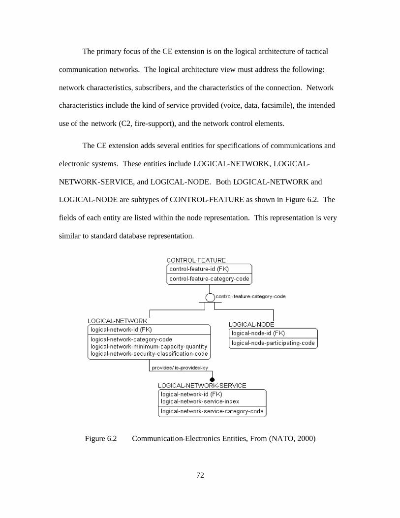
72
The primary focus of the CE extension is on the logical architecture of tactical
communication networks. The logical architecture view must address the following:
network characteristics, subscribers, and the characteristics of the connection. Network
characteristics include the kind of service provided (voice, data, facsimile), the intended
use of the network (C2, fire-support), and the network control elements.
The CE extension adds several entities for specifications of communications and
electronic systems. These entities include LOGICAL-NETWORK, LOGICAL-
NETWORK-SERVICE, and LOGICAL-NODE. Both LOGICAL-NETWORK and
LOGICAL-NODE are subtypes of CONTROL-FEATURE as shown in Figure 6.2. The
fields of each entity are listed within the node representation. This representation is very
similar to standard database representation.
Figure 6.2 Communication-Electronics Entities, From (NATO, 2000)

73
F. COMMUNICATIONS-ELECTRONICS EXTENSION EXAMPLES
This section will examine two examples utilizing the CE extension. Both
examples illustrate how logical networks can be represented using the GH model. The
first network is a two-node network and the second is a four-node network. The
graphical representation of the examples is shown in Figure 6.3.
0101
organisation-id 041
0307
organisation-id 012
A
0909
0101
organisation-id 041
0427 0307
organisation-id 012
0517
organisation-id 085
B
0909
0744
0444
Figure 6.3 Two Examples of Logical Networks, After (NATO, 2000)
1. Two-Node Network (Example A)
The first example contains two organizational subscribers connected by a single
bi-directional link. The relevant information from the example is contained in Table 6.1.
The network is modeled using two LOGICAL-NODES and participating-codes set for
transmit/receive. Next are the participating organizations identified by organization-id
and the control-feature-id corresponding to their node-id. The LOGICAL-NETWORK
describes the network connection between the subscribers. In the example, the network
capacity is 28800 baud at the NATO SECRET level. The final section is used to
associate the LOGICAL-NODE and LOGICAL-NETWORK.

74
(a) LOGICAL-NODE logical-node-id logical-node-participating-code
0101 Transmitting/receiving 0307 Transmitting/receiving
(b) ORGANISATION-CONTROL-FEATURE -ASSOCIATION ***-subject-organisation-id ***-object-control-feature-id ***-index ***-category-code
012 0307 1 Is user of 041 0101 1 Is user of
Note: *** = organisation-control-feature-association
(c) LOGICAL-NETWORK ***-id ***-category-code ***-minimum-capacity-quantity ***-security-classification-code
0909 Sole user network 28,800 NATO SECRET
Note: *** = logical-network
(d) CONTROL-FEATURE-CONTROL-FEATURE-ASSOCIATION ***-subject-control-feature-id ***-object-control-feature-id ***-index ***-category-code
0307 0909 1 Is part of 0101 0909 1 Is part of
Note: *** = control- feature-control- feature-association
Table 6.1 Two Node Network Example Expressed using Global Hub Notation, From (NATO, 2000)
2. Four-Node Netwo rk (Example B)
The second example, Figure 6.3, builds on Example A by adding an organization
that is a receive-only subscriber of the network. An addition link is added that is
modeled as a separate LOGICAL-NETWORK. The two links are then also modeled as a
LOGICAL-NETWORK. The data for the example is contained in Table 6.2.

75
(a) LOGICAL-NODEs logical-node-id logical-node-participating-code
0101 Transmitting/receiving 0307 Transmitting/receiving 0427 Transmitting 0517 Receiving
(b) ORGANISATION-CONTROL-FEATURE -ASSOCIATION ***-subject-
organisation-id ***-object-control-
feature-id ***-
index ***-category-
code
012 0307 1 Is user of 012 0427 1 Is user of 041 0101 1 Is user of 085 0517 1 Is user of
Note: *** denotes “organisation-control-feature-association”.
(c) LOGICAL-NETWORK
***-id ***-category-code ***-minimum-capacity-quantity ***-security-classification-code
0909 Sole user network 28,800 NATO SECRET 0744 Sole user network 14.400 NATO SECRET 0444 Compound network 14.400 —
Note: *** = logical-network
(d) CONTROL-FEATURE-CONTROL-FEATURE -ASSOCIATION ***-subject-control-
feature-id ***-object-control-
feature-id ***-
index ***-category-
code
0307 0909 1 Is part of 0101 0909 1 Is part of 0307 0744 1 Is part of 0507 0744 1 Is part of 0909 0444 1 Is part of 0744 0444 1 Is part of
Note: *** denotes “control-feature-control-feature-association”.
Table 6.2 Four Node Network Example Expressed using Global Hub Notation, From (NATO, 2000)
The first connection in this example, between ORGANIZATIONs with
organization- ids 012 and 041 is modeled as it was in Example A. There is a second
logical node assigned to the ORGANIZATION with organization- id 012 because it has

76
two connections with different characteristics. The new LOGICAL-NETWORK is
specified similarly as the one in Example A while the compound network is specified as
an association of the two point-to-point LOGICAL-NETWORKS.
G. CHAPTER SUMMARY
The proposed NATO Generic Hub and LC2IEDM increase the effective and
efficiency of disparate systems that need to exchange data. The GH data model supports
higher- level information interchange by standardizing the way the information is
exchanged. This format is robust and flexible enough to allow a full range of battlespace
representations to be created.
The Communications-Electronics extension to LC2IEDM represents
communication and information processes and systems. It primarily focuses on the
logical network representation of tactical networks. Modifications to provide strategic
and commercial network representations are being considered. This will significantly
extend the usefulness of the model.

77
VIII. DEMONSTRATION OF SIMULATION RESULTS
A. INTRODUCTION
This chapter describes and presents antenna prototypes and example scenes
designed for tactical signal visualization. The goal for these representations is to provide
intuitively obvious visualizations. Antenna and signal model prototypes are presented
first. The prototypes are then incorporated into scenarios showing probable tactical
employment. Finally, this chapter discusses the potential uses for this system.
B. DEMONSTRATION OF VISUALIZATION TECHNIQUES
This section outlines the different visualization models created for this thesis.
The primitives shown are graphics-palette capabilities such as: color, transparency, and
shapes. These are the building blocks for the system prototypes. The prototypes provide
the user with a customizable object that can be used in different ways without having to
alter the underlying model.
1. Signal Primitives
This section displays the signal primitives used to create the visualization models.
Figure 8.1 displays the beam prototypes used in point-to-point communication
applications. The cones on the left are useful to display the spreading of the beam pattern
as the distance between transmitter and receiver increases. The spreading also presents a
challenge because it can take up much of the scene at the receiving end obscuring other
features and this can also be very narrow and “difficult to see” at the transmitter. These
usability constraints led to the development of the cylindrical displays on the right side of
Figure 8.1. The cylinders are effective for point-to-point links because they provide a

78
constant diameter for all distances. Figure 8.1 displays both the solid and wire frame
views that a designer could use.
Figure 8.1 Beam Cone and Beam Cylinder Signal Prototypes Shown as Solid and Wire Frame Objects
Coverage domes (or half-domes) are an effective way to present area coverage
systems that communicate with multiple senders or receivers. Two domes are shown in
Figure 8.2. The frequency of a radio’s transmitter or receiver is shown using the color of
the coverage dome. The coverage domes contain a prototype that generates a color for
the dome based on the declared frequency. This will help prevent frequency interference
and show all users communicating on a given frequency. Future work needs to compare
and contrast usage paradigms for the assignment of graphics rendering parameters to
communications parameters.

79
Figure 8.2 Two Area-Coverage Domes
2. System Visualization
This section presents the system visualizations designed for demonstrating both
SHF and UHF communications. Figure 8.3 shows a pair of Tropo Satellite Support
Radios (TSSRs) with an established link.

80
Figure 8.3 Two Tropo Satellite Support Radios (TSSR) with an Established Direct-Path Link
The next SHF system is a TRC-170 operating in troposcatter mode by bouncing
their signals off the troposphere. Figure 8.4 shows an aerial view of two TRC-170s
connected using conic beams.

81
Figure 8.4 High Above Two TRC-170s Operating in Troposcatter Mode
The omni-directional visualizations, typically VHF or UHF systems, use domes to
indicate both the receivers and transmitters within a scene. They are not differentiated
except when the transmitter is transmitting. The domes are not intended to represent
coverage area for the system. Some of the systems have coverage areas of 20 miles line-
of-sight. The domes quickly grew too large to represent more than a few radios. This is
an area where 2D visualization is superior to 3D representation.
Figure 8.5 shows 6 radio domes using 3 different frequencies. Each color
represents a frequency. The two domes with the red lightning bolts indicate they are
transmitters. The other four are receivers. The two yellow domes are larger than the
other four indicating those radios are in the process of communicating.

82
Figure 8.5 Omni Directional Receivers and Transmitters with the Two Larger Domes Indicating Active Communication
Satellite system visualizations are difficult because of the enormous coverage
areas and distances between the satellite and ground stations. It is useful to depict ground
receivers and convey connectivity information to users. It is not possible to intelligibly
view the operating area from a satellite in geosynchronous orbit because of the great
distance involved. Figure 8.6 shows a satellite ground station with a conical beam
emanating from it.
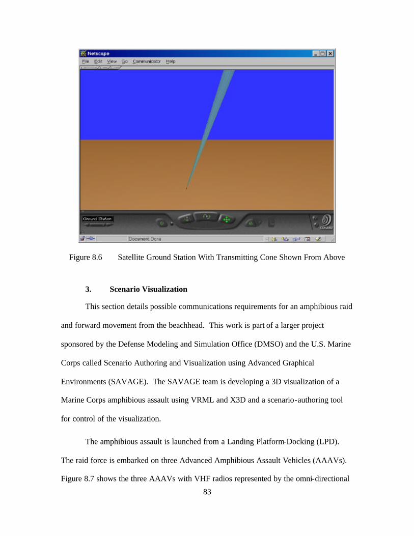
83
Figure 8.6 Satellite Ground Station With Transmitting Cone Shown From Above
3. Scenario Visualization
This section details possible communications requirements for an amphibious raid
and forward movement from the beachhead. This work is part of a larger project
sponsored by the Defense Modeling and Simulation Office (DMSO) and the U.S. Marine
Corps called Scenario Authoring and Visualization using Advanced Graphical
Environments (SAVAGE). The SAVAGE team is developing a 3D visualization of a
Marine Corps amphibious assault using VRML and X3D and a scenario-authoring tool
for control of the visualization.
The amphibious assault is launched from a Landing Platform-Docking (LPD).
The raid force is embarked on three Advanced Amphibious Assault Vehicles (AAAVs).
Figure 8.7 shows the three AAAVs with VHF radios represented by the omni-directional

84
domes. The command vehicle (center) has two radios represented by the two domes.
The yellow dome represents a transmitter set to the same frequency as the other two
AAAVs. Those radios are in standby mode indicated by the smaller domes. The blue
dome on the command vehicle is a receiver. It is larger than the other domes indicating it
is receiving from the LPD in the background of the scene. The cone extending from the
LPD indicates a satellite connection.
Figure 8.7 3 Advanced Amphibious Assault Vehicles Shown Communicating After Launching from the Landing Platform-Docking
Figure 8.8 shows an overview of the beach communications. It includes two
TRC-170 pairs operating in troposcatter mode. It includes a satellite link and two short
TSSR point-to-point links. This scenario displays the possible system representations

85
that may be used by tactical units. It is not meant to represent the actual tactical doctrine
for communications after an amphibious raid.
2 Pairs of TRC-170 Operating in Troposcatter Mode
Satellite Ground Station Communicating With Geostationary Satellite
TSSR Not Connected
TSSR Connected
Figure 8.8 Follow-on Communication using Troposcatter Satellite Support Radios and TRC-170 in Troposcatter Mode
C. USE OF VISUALIZATION IN COMMUNICATION PLANNING AND OPERATIONS
Both signal planners and operators will benefit from better understanding of
communication capabilities. Signal planners are better able to support operators through
problem recognition and correction. This includes frequency deconfliction, recognition
of degraded signal areas, and optimum antenna placement based on terrain. The
operators can better understand the effects that maneuver operations may have on their
communications. They can also see coverage areas that in turn influence operating
decisions and choice of operating areas.

86
D. CHAPTER SUMMARY
Signal planners and operators will benefit from the increased understanding of the
tactical situation through the use of 3D visualizations. The visualizations shown in this
chapter demonstrate what can be done using DIS-Java-VRML open-source toolkit. Both
the 3D communications building blocks and scenarios created for this seek to
demonstrate what can be developed and the utility of this development.

87
IX. CONCLUSIONS AND RECOMMENDATIONS
A. INTRODUCTION
This chapter outlines the conclusions drawn from the communication
visualization work completed for this thesis. The future work necessary to enhance these
exemplar scenes are and work are also addressed.
B. THESIS CONCLUSIONS
1. 3D Tactical Visualization Of Communications
The tactical scenes and scenarios developed for this thesis demonstrate that it is
possible to create 3D visualizations of communications signals and systems. The goal for
these visualizations was to be inherently obvious to the viewer. These visualizations do
convey useful information that is not currently available in the 2D planning systems used
throughout the DoD. These visualizations, however, are not inherently obvious. Both
signal planners and operators who must understand communication coverage areas and
connectivity between forces can use these tactical visualizations to gain a better
understanding of the battlefield.
Using actual terrain representations can allow users to determine interference or
possible signal degradation visually facilitating problem discovery. It is still difficult to
visualize communication systems connected over long distances (greater than 10 miles).
To view the entirety of such visualizations, the viewpoint must be a long distance from
the system.

88
2. Open-Source Software Toolkits
The open source toolkit consisting of VRML and X3D graphics, IEEE DIS, and
the Java language provides a thorough framework that can be utilized to develop 3D
communication visualizations in a relatively short amount of time (less than 1 year).
These visualizations can be displayed using commercial web technology on commodity
PCs widely available throughout the DoD. The software toolkit also enables
collaborative planning at different locations through network connectivity.
3. Operation Orders Using The Global Hub Data Model
The Global Hub data model is currently proposed for the interchange of data
between NATO systems. It provides a robust capability for many operational scenarios
by providing the ability to define equipment and objects and relationships. It represents
logical networks defined by who is connected to whom. It does not however have the
fidelity to fully represent all of the communication information contained within an
operation order annex K.
C. RECOMMENDED FUTURE WORK
1. Physics-Based Signal Propagation
The current signal visualizations are done independent of any signal propagation
models. The use of the DIS transmitter, receiver and signal PDU parameters and terrain
data can be used to compute signal strength and degradation areas. This can provide
signal planners increased understanding and make planning easier.
2. Dynamic 3D Terrain Visualization
The current communication system models could be used in any virtual
environment. Currently, there are only a few battlefield scenarios containing actual

89
terrain data. While Digital Terrain Elevation Data is available for nearly the entire world,
the ability to auto-generate 3D representations does not exist. The ability to auto-
generate 3D terrain given a set of coordinates would facilitate battlefield environment
creation for any operating location in the world.
3. Autogeneration of 3D from an Operation Order Annex K
Current signal planning is accomplished manually using some of the 2D systems
discussed in this thesis. It will be extremely useful for these systems to be able to process
operation order information dealing with communications and produce 3D
representations of the tactical battlespace. This ability has been shown using an XML
Air Tasking Order (ATO) and should be applied to communications planning. This
would require the adoption an extensible operation order for communication like XML-
MTF or the Global Hub data model and the 3D models for the visualization.
4. Virtual Reality Toolbox
MATLAB by MathWorks, Inc. (www.mathworks.com) recently incorporated
support for VRML with the addition of the Virtual Reality Toolbox by Humusoft, Inc
(www.humusoft.com). Matlab contains signal representation capabilities and supports
equation development. These capabilities and the addition of the VRML toolkit should
be investigated for future use in 3D signal representations.
5. MathML
The possible integration of MathML as a scripting language and presentation
format for 3D equations may hold great promise for extending the functionality of
VRML / X3D. MathML could be used to store propagation equations and signal and
path loss equations. MathML should be investigated because it stores equations in a

90
language-neutral way. Such language neutrality can facilitate the storing of equations for
future compatibility with numerous computational systems.

91
APPENDIX A. ABBREVIATIONS
2D Two-Dimensional 3D Three-Dimensional AAAV Advanced Amphibious Assault Vehicles API Application Program Interface ATO Air Tasking Order BPS bits per second C3 Command, Control, and Communication C4 Command, Control, Communications, and
Computer CAD Computer-Aided Design CE Communications-Electronics CECOM US Army Communications Electronics Command DARPA Defense Advanced Research Projects Agency DIS Distribute Interactive Simulation DISA Defense Information Systems Agency DMSO Defense Modeling and Simulation Office DTD Document Type Definition DTED Digital Terrain Elevation Data EHF Extremely High Frequency FM Frequency Modulated GH Generic Hub GHz Gigahertz HTML Hypertext Markup Language IDA Institute for Defense Analysis IEEE Institute of Electrical and Electronic Engineers ISO International Standards Organization JRE Java Runtime Environment LC2IEDM Land C2 Information Exchange Data Model LEO Low Earth Orbiting LOD Level of Detail LPD Landing Platform-Docking LSVE Large Scale Virtual Environments MCTSSA Marine Corps Tactical Systems Support Activity MGRS Military Grid Reference System MHz megahertz MSE-NPT Mobile Subscribe Equipment- Network Planning
Tool NATO North Atlantic Treaty Organization NC3TA NATO C3 Technical Architecture NCW Network Centric Warfare NIMA National Imaging and Mapping Agency NUWC Naval Undersea Warfare Command OPORD Operations Order

92
PC Personal Computer PDU Protocol Data Units PLRS Position Locating and Reporting System RCP Radio Communication Protocol RF Radio Frequency RGB Red Green Blue SAVAGE Scenario Authoring and Visualization using
Advanced Graphical Environments SEDRIS Synthetic Environment Data Representation and
Interchange Specification SGML Standard Generalized Markup Language SHF Super High Frequency SIMNET Simulator-Network SPEED System Planning, Engineering and Evaluation
Device SRI Stanford Research Institute STK Satellite Tool Kit TSSR Tropo Satellite Support Radio UHF Ultra High Frequency USMC United States Marine Corps USMTF United States Message Text Format VHF Very High Frequency VLF Very Low Frequency VRML Virtual Reality Modeling Language W3C World Wide Web Consortium WWW World Wide Web X3D Extensible 3D XML Extensible Markup Language XML-MTF Extensible Markup Language Message Text Format XSL Extensible Stylesheet Language

93
APPENDIX B. SOFTWARE AVAILABILITY AND INSTALLATION SUMMARY
A. INTRODUCTION
This appendix describes the availability and installation for most of the software
packages used to generate this thesis. Much of the software is included on the CD with
this thesis. If the CD is unavailable, this section provides instructions for downloading
and installing the software.
B. VIRTUAL REALITY MODELING LANGUAGE (VRML) BROWSER
To view Virtual Reality Modeling Language (VRML) scenes, one must have a
VRML-capable browser. This section describes the software availability and an
overview of the installation instructions. The current VRML viewer of choice is Cosmo
Player running on Netscape Navigator 4.7 because it fully supports Java integration.
1. Netscape Navigator 4.7
If you do not have Netscape Navigator installed on your system, download it from
http://home.netscape.com/download/sd_cc32d477en.html and follow the installation
instructions.
2. Cosmo Player
Cosmo Player (version 2.1.1) VRML plug- in is available at
http://www.cai.com/cosmo/ . To install Cosmo Player, download the appropriate player
for your system. Follow the directions on the web site. Cosmo Player works best with
Netscape Navigator 4.7.
These two steps will allow you to view VRML 3D files.

94
3. Naval Postgraduate School (NPS) Military Models Library
The Naval Postgraduate School Military Models Library is maintained at
http://web.nps.navy.mil/~brutzman/vrml/examples/NpsMilitaryModels/toc.html and can
be viewed individually or downloaded as a complete archive. All of the communication
models developed for this thesis are available in the Communications And Sensors
folder.
4. Extensible 3D (X3D) Edit
This section details the steps necessary to view and create Extensib le 3D (X3D)
models in X3D Edit. X3D Edit was used to create all of the models contained in this
thesis. Step-by-step instructions are available at
http://www.web3D.org/TaskGroups/x3d/translation/README.X3D-
Edit.html#Installation
The Java Runtime Environment (JRE) is necessary for installation of X3D Edit.
The JRE is available from Sun Microsystems at http://java.sun.com/j2se/1.3 . This is a
large file and should be downloaded over a high-speed connection if at all possible.
Next, download and install Xeena from IBM Alphaworks
http://www.alphaWorks.ibm.com/tech/xeena . Be sure to install version 1.2EA.
X3D-Edit is available from
http://www.web3D.org/TaskGroups/x3d/translation/X3D-Edit.zip It should be unzipped
to the top level of the C:\ drive.
Again, full installation instructions are provided at
http://www.web3D.org/TaskGroups/x3d/translation/README.X3D-
Edit.html#Installation

95
5. DIS-Java-VRML Software Toolkit
The DIS-Java-VRML software toolkit is available at
http://www.web3d.org/WorkingGroups/vrtp/dis-java-vrml/download.html with complete
installation instructions.

96
THIS PAGE INTENTIONALLY LEFT BLANK

97
APPENDIX C. SIGNAL PROTOTYPES
A. SIGNAL MODELS
This appendix contains code for the simple signal models that are used throughout this thesis. They include the beam prototypes, which are
available at: http://web.nps.navy.mil/~brutzman/vrml/examples/NpsMilitaryModels/CommunicationsAndSensors/Beam/chapter.html and
the half dome prototypes, which are available at:
http://web.nps.navy.mil/~brutzman/vrml/examples/NpsMilitaryModels/CommunicationsAndSensors/HalfDome/chapter.html
This appendix contains the following files of X3D Code:
BeamConePrototype BeamConeExample
BeamCylinderPrototype BeamCylinderExample HalfDome

98
B. BEAM CONE PROTOTYPE
<?xml version="1.0" encoding="UTF-8"?> <!DOCTYPE X3D PUBLIC "http://www.web3D.org/TaskGroups/x3d/translation/x3d-compact.dtd" "file://localhost/C:/www.web3D.org/TaskGroups/x3d/translation/x3d-compact.dtd"> <X3D> <Header> <meta name='filename' content='BeamConePrototype.xml'/> <meta name='author' content='Don Brutzman'/> <meta name='revised' content='December 7, 2000'/> <meta name='description' content='Produce wireframe or transparent beam cones.'/> <meta name='url' content='http://web.nps.navy.mil/~brutzman/vrtp/demo/auv/BeamConePrototype.xml http://www.web3D.org/WorkingGroups/vrtp/demo/auv/BeamConePrototype.xml'/>
<meta name='generator' content='X3D-Edit, http://www.web3D.org/TaskGroups/x3d/translation/README.X3D-Edit.html'/> </Header> <Scene>
<!-- Produce wireframe or transparent beam cones. Typical uses include propeller/thruster water flow or line-of-sight sonar/radar/light beams. Negative range values invert base and apex at same relative: location. Default beam with apex at (0,0,0) and base of radius 1 in x-z plane at (1,0,0). --> <ProtoDeclare name='BeamCone'> <!-- contact: (communications) is transmitted signal in contact with receiver, or, (sensor) is a target return detected? --> <!-- range: distance in meters along x axis --> <!-- defaultRange: distance in meters, used until eventIn range sent --> <!-- beamHeightDegrees: degrees across vertical y axis --> <!-- beamWidthDegrees: degrees across horizontal z axis --> <!-- transparency: 1 = fully transparent, wireframe only --> <!-- eventIn, eventOut and field semantics must be retained due to exposedField not being allowed in VRML 97 scripts (unfortunately) --> <field name='contact' type='Boolean' value='false' IS='DETECTION.contact' vrml97Hint='eventIn'/> <field name='range' type='Float' value='0' IS='BEAM_CALCULATE.range' vrml97Hint='eventIn'/>

99
<field name='defaultRange' type='Float' value='1' IS='BEAM_CALCULATE.defaultRange' vrml97Hint='field'/> <field name='wireframe' type='Boolean' value='true' IS='DETECTION.wireframe' vrml97Hint='field'/> <field name='solid' type='Boolean' value='true' IS='DETECTION.solid' vrml97Hint='field'/> <field name='beamHeightDegrees' type='Float' value='10' IS='BEAM_CALCULATE.beamHeightDegrees' vrml97Hint='field'/> <field name='beamWidthDegrees' type='Float' value='10' IS='BEAM_CALCULATE.beamWidthDegrees' vrml97Hint='field'/> <field name='contactColor' type='Color' value='.8 .1 .1' IS='WIRE_COLOR.emissiveColor CONE_COLOR.emissiveColor DETECTION.contactColor' vrml97Hint='field'/> <field name='noContactColor' type='Color' value='.3 .5 .5' IS='DETECTION.noContactColor' vrml97Hint='field'/> <field name='transparency' type='Float' value='0' IS='WIRE_COLOR.transparency CONE_COLOR.transparency DETECTION.transparency' vrml97Hint='field'/> <!-- BEAM_CONTROL beam scaling is controlled by range/beamHeightDegrees/beamWidthDegrees/direction inputs --> <Transform DEF='BEAM_CONTROL'>
<Switch DEF='WIREFRAME_SWITCH' whichChoice='0'> <WorldInfo info='initial choice is null node (WorldInfo), meaning no wireframe beam'/> <Shape>
<Appearance> <Material DEF='WIRE_COLOR' diffuseColor='.1 .1 .1'/> </Appearance> <IndexedLineSet coordIndex='0 13 -1, 1 2 3 4 5 6 7 8 9 10 11 12 1 -1, 0 1 -1, 0 2 -1, 0 3 -1, 0 4 -1, 0 5 -1, 0 6 -1, 0 7 -1, 0 8 -1, 0 9 -1, 0 10 -1, 0 11 -1, 0 12 -1'> <Coordinate point='0 0 0, 1 1 0, 1 0.86 0.50, 1 0.50 0.86, 1 0 1.0, 1 -0.50 0.86, 1 -0.86 0.50, 1 -1 0, 1 -0.86 -0.50, 1 -0.50 -0.86, 1 0 -1.0, 1 0.50 -0.86, 1 0.86 -0.50, 1 0 0'/> </IndexedLineSet>
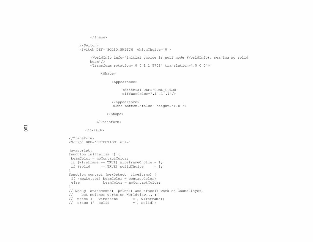
100
</Shape> </Switch> <Switch DEF='SOLID_SWITCH' whichChoice='0'> <WorldInfo info='initial choice is null node (WorldInfo), meaning no solid beam'/> <Transform rotation='0 0 1 1.5708' translation='.5 0 0'> <Shape> <Appearance> <Material DEF='CONE_COLOR' diffuseColor='.1 .1 .1'/> </Appearance> <Cone bottom='false' height='1.0'/>
</Shape> </Transform> </Switch>
</Transform> <Script DEF='DETECTION' url=' javascript: function initialize () { beamColor = noContactColor; if (wireframe == TRUE) wireframeChoice = 1; if (solid == TRUE) solidChoice = 1; } function contact (newDetect, timeStamp) { if (newDetect) beamColor = contactColor; else beamColor = noContactColor; } // Debug statements: print() and trace() work on CosmoPlayer, // but neither works on Worldview... :( // trace (' wireframe =', wireframe); // trace (' solid =', solid);
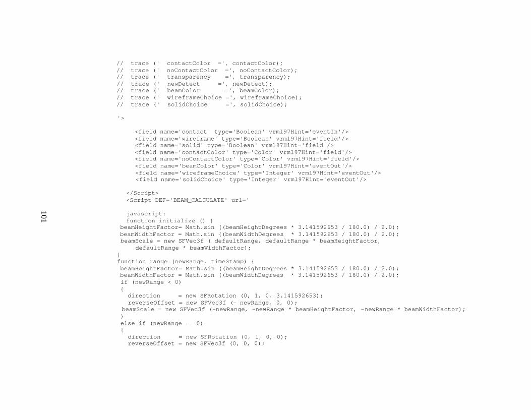
101
// trace (' contactColor =', contactColor); // trace (' noContactColor =', noContactColor); // trace (' transparency =', transparency); // trace (' newDetect =', newDetect); // trace (' beamColor =', beamColor); // trace (' wireframeChoice =', wireframeChoice); // trace (' solidChoice =', solidChoice); '> <field name='contact' type='Boolean' vrml97Hint='eventIn'/> <field name='wireframe' type='Boolean' vrml97Hint='field'/> <field name='solid' type='Boolean' vrml97Hint='field'/> <field name='contactColor' type='Color' vrml97Hint='field'/> <field name='noContactColor' type='Color' vrml97Hint='field'/> <field name='beamColor' type='Color' vrml97Hint='eventOut'/> <field name='wireframeChoice' type='Integer' vrml97Hint='eventOut'/> <field name='solidChoice' type='Integer' vrml97Hint='eventOut'/>
</Script> <Script DEF='BEAM_CALCULATE' url=' javascript: function initialize () {
beamHeightFactor= Math.sin ((beamHeightDegrees * 3.141592653 / 180.0) / 2.0); beamWidthFactor = Math.sin ((beamWidthDegrees * 3.141592653 / 180.0) / 2.0); beamScale = new SFVec3f ( defaultRange, defaultRange * beamHeightFactor,
defaultRange * beamWidthFactor); } function range (newRange, timeStamp) { beamHeightFactor= Math.sin ((beamHeightDegrees * 3.141592653 / 180.0) / 2.0); beamWidthFactor = Math.sin ((beamWidthDegrees * 3.141592653 / 180.0) / 2.0); if (newRange < 0) { direction = new SFRotation (0, 1, 0, 3.141592653); reverseOffset = new SFVec3f (- newRange, 0, 0);
beamScale = new SFVec3f (-newRange, -newRange * beamHeightFactor, -newRange * beamWidthFactor); } else if (newRange == 0) { direction = new SFRotation (0, 1, 0, 0); reverseOffset = new SFVec3f (0, 0, 0);

102
beamScale = new SFVec3f ( .0001, .0001, .0001 ); } else { direction = new SFRotation (0, 1, 0, 0); reverseOffset = new SFVec3f (0, 0, 0); beamScale = new SFVec3f (newRange, newRange * beamHeightFactor, newRange * beamWidthFactor); } } // Note above that VRML scale factor triplets all equal to zero are not allowed // Debug statements: print() and trace() work on CosmoPlayer, // but neither works on Worldview... :( // trace (' beamWidthDegrees =', beamWidthDegrees); // trace (' beamHeightDegrees=', beamHeightDegrees); // trace (' initial beamScale=', beamScale); '>
<field name='range' type='Float' vrml97Hint='eventIn'/> <field name='defaultRange' type='Float' vrml97Hint='field'/> <field name='beamHeightDegrees' type='Float' vrml97Hint='field'/> <field name='beamWidthDegrees' type='Float' vrml97Hint='field'/> <field name='beamScale' type='Vector3Float' vrml97Hint='eventOut'/> <field name='direction' type='Rotation' vrml97Hint='eventOut'/>
<field name='reverseOffset' type='Vector3Float' vrml97Hint='eventOut'/> </Script> <ROUTE fromNode='DETECTION' fromField='beamColor' toNode='WIRE_COLOR' toField='emissiveColor'/> <ROUTE fromNode='DETECTION' fromField='beamColor' toNode='CONE_COLOR' toField='emissiveColor'/> <ROUTE fromNode='DETECTION' fromField='wireframeChoice' toNode='WIREFRAME_SWITCH' toField='whichChoice'/> <ROUTE fromNode='DETECTION' fromField='solidChoice' toNode='SOLID_SWITCH' toField='whichChoice'/> <ROUTE fromNode='BEAM_CALCULATE' fromField='beamScale' toNode='BEAM_CONTROL' toField='scale'/> <ROUTE fromNode='BEAM_CALCULATE' fromField='direction' toNode='BEAM_CONTROL' toField='rotation'/> <ROUTE fromNode='BEAM_CALCULATE' fromField='reverseOffset' toNode='BEAM_CONTROL' toField='translation'/>

103
</ProtoDeclare> <!-- Viewable geometry for this scene is anchored text that links to an example showing
ExternProtoDeclare usage of BeamCone --> <WorldInfo info='Produce wireframe or transparent beam cones.' title='BeamConeProto'/> <NavigationInfo type='"EXAMINE" "ANY"'/> <Viewpoint position='0 0 15'/> <Anchor url='"BeamConeExample.wrl" "file:///C|/vrtp/demo/auv/BeamConeExample.wrl" "file:///D|/vrtp/demo/auv/BeamConeExample.wrl" "http://web.nps.navy.mil/~brutzman/vrtp/demo/auv/BeamConeExample.wrl" "http://www.web3D.org/WorkingGroups/vrtp/demo/auv/BeamConeExample.wrl"'> <Shape> <Appearance> <Material diffuseColor='0 1 1' emissiveColor='0 1 1'/>
</Appearance> <Text string='"BeamConePrototype" "is a Prototype definition file." "" "To see an example scene," "click this text and view" "BeamConeExample."'> <FontStyle justify='"MIDDLE" "MIDDLE"'/>
</Text> </Shape> </Anchor> </Scene> </X3D> <!-- Tag color codes: <NodeName attribute='value'/> -->
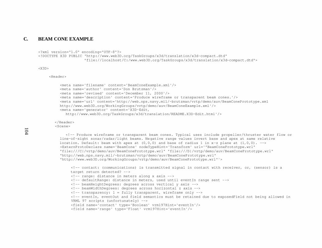
104
C. BEAM CONE EXAMPLE
<?xml version="1.0" encoding="UTF-8"?> <!DOCTYPE X3D PUBLIC "http://www.web3D.org/TaskGroups/x3d/translation/x3d-compact.dtd" "file://localhost/C:/www.web3D.org/TaskGroups/x3d/translation/x3d-compact.dtd"> <X3D> <Header> <meta name='filename' content='BeamConeExample.xml'/> <meta name='author' content='Don Brutzman'/> <meta name='revised' content='December 11, 2000'/> <meta name='description' content='Produce wireframe or transparent beam cones.'/> <meta name='url' content='http://web.nps.navy.mil/~brutzman/vrtp/demo/auv/BeamConePrototype.xml http://www.web3D.org/WorkingGroups/vrtp/demo/auv/BeamConeExample.xml'/> <meta name='generator' content='X3D-Edit,
http://www.web3D.org/TaskGroups/x3d/translation/README.X3D-Edit.html'/> </Header> <Scene> <!-- Produce wireframe or transparent beam cones. Typical uses include propeller/thruster water flow or
line-of-sight sonar/radar/light beams. Negative range values invert base and apex at same relative location. Default: beam with apex at (0,0,0) and base of radius 1 in x-z plane at (1,0,0). --> <ExternProtoDeclare name='BeamCone' nodeTypeHint='Transform' url='"BeamConePrototype.wrl" "file:///C|/vrtp/demo/auv/BeamConePrototype.wrl" "file:///D|/vrtp/demo/auv/BeamConePrototype.wrl" "http://web.nps.navy.mil/~brutzman/vrtp/demo/auv/BeamConePrototype.wrl" "http://www.web3D.org/WorkingGroups/vrtp/demo/auv/BeamConePrototype.wrl"'> <!-- contact: (communications) is transmitted signal in contact with receiver, or, (sensor) is a target return detected? --> <!-- range: distance in meters along x axis --> <!-- defaultRange: distance in meters, used until eventIn range sent --> <!-- beamHeightDegrees: degrees across vertical y axis --> <!-- beamWidthDegrees: degrees across horizontal z axis --> <!-- transparency: 1 = fully transparent, wireframe only --> <!-- eventIn, eventOut and field semantics must be retained due to exposedField not being allowed in VRML 97 scripts (unfortunately) --> <field name='contact' type='Boolean' vrml97Hint='eventIn'/> <field name='range' type='Float' vrml97Hint='eventIn'/>
105
<field name='defaultRange' type='Float' vrml97Hint='field'/> <field name='wireframe' type='Boolean' vrml97Hint='field'/> <field name='solid' type='Boolean' vrml97Hint='field'/> <field name='beamHeightDegrees' type='Float' vrml97Hint='field'/> <field name='beamWidthDegrees' type='Float' vrml97Hint='field'/> <field name='contactColor' type='Color' vrml97Hint='field'/> <field name='noContactColor' type='Color' vrml97Hint='field'/> <field name='transparency' type='Float' vrml97Hint='field'/> </ExternProtoDeclare> <!-- Viewable geometry for this scene --> <WorldInfo info='Produce wireframe or transparent beam cones' title='BeamConeExample'/> <NavigationInfo type='"EXAMINE" "ANY"'/> <Viewpoint description='BeamCone example' position='5 0 10'/> <Group> <ProtoInstance DEF='SAMPLE_BEAMCONE' name='BeamCone'>
<fieldValue name='defaultRange' value='5'/> <fieldValue name='beamHeightDegrees' value='24'/> <fieldValue name='beamWidthDegrees' value='5'/> <fieldValue name='transparency' value='0.2'/> <fieldValue name='wireframe' value='true'/> <fieldValue name='solid' value='true'/>
</ProtoInstance> <Transform translation='5 -3 0'> <Billboard> <Shape> <Appearance> <Material diffuseColor='.8 .8 0'/> </Appearance> <Text string='touch text to toggle contact-mode rendering'> <FontStyle justify='"MIDDLE" "MIDDLE"' size='0.6'/>

106
</Text> </Shape> </Billboard> <TouchSensor DEF='TEXT_TOUCH'/> </Transform> <TimeSensor DEF='CLOCK' cycleInterval='10' loop='true'/> <ScalarInterpolator DEF='RANGE_INTERPOLATOR' key='0 .4, .4 .5, .5 .9, .9 1' keyValue='0.01 10, 0 0, -0.01 -10, 0 0'/> </Group> <ROUTE fromNode='TEXT_TOUCH' fromField='isOver' toNode='SAMPLE_BEAMCONE' toField='contact'/> <ROUTE fromNode='CLOCK' fromField='fraction_changed' toNode='RANGE_INTERPOLATOR' toField='set_fraction'/> <ROUTE fromNode='RANGE_INTERPOLATOR' fromField='value_changed'
toNode='SAMPLE_BEAMCONE' toField='range'/> </Scene> </X3D>
<!-- Tag color codes: <NodeNme attribute='value'/> -->
D. BEAM CYLINDER PROTOTYPE
<?xml version="1.0" encoding="UTF-8"?>

107
<!DOCTYPE X3D PUBLIC "http://www.web3D.org/TaskGroups/x3d/translation/x3d-compact.dtd" "file://localhost/C:/www.web3D.org/TaskGroups/x3d/translation/x3d-compact.dtd"> <X3D> <Header> <meta name='filename' content='BeamCylinderPrototype.xml'/> <meta name='author' content='Don Brutzman'/> <meta name='created' content='February 25, 2001'/> <meta name='description' content='Produce wireframe or transparent beam cylinders.'/> <meta name='url' content=
'http://www.web3D.org/TaskGroups/x3d/translation/examples/MilitaryModels/Sensors/Beam/BeamCylinderPrototype.xml'/> <meta name='generator' content='X3D-Edit, http://www.web3D.org/TaskGroups/x3d/translation/README.X3D-Edit.html'/> </Header>
<Scene> <!-- Produce wireframe or transparent beam cylinders. Typical uses include propeller/thruster water flow or line-of-sight sonar/radar/light beams. Negative range values invert base and apex at same relative location. Default: beam with apex at (0,0,0) and base of radius 1 in x-z plane at (1,0,0). --> <ProtoDeclare name='BeamCylinder'>
<!-- contact: (communications) is transmitted signal in contact with receiver, or, (sensor) is a
target return detected? --> <!-- range: distance in meters along x axis --> <!-- defaultRange: distance in meters, used until eventIn range sent --> <!-- beamHeightDegrees: degrees across vertical y axis --> <!-- beamWidthDegrees: degrees across horizontal z axis --> <!-- transparency: 1 = fully transparent, wireframe only --> <!-- eventIn, eventOut and field semantics must be retained due to exposedField not being allowed in VRML 97 scripts (unfortunately) --> <field name='contact' type='Boolean' value='false' IS='DETECTION.contact' vrml97Hint='eventIn'/> <field name='range' type='Float' value='0' IS='BEAM_CALCULATE.range' vrml97Hint='eventIn'/> <field name='defaultRange' type='Float' value='1' IS='BEAM_CALCULATE.defaultRange' vrml97Hint='field'/> <field name='wireframe' type='Boolean' value='true' IS='DETECTION.wireframe'

108
vrml97Hint='field'/> <field name='solid' type='Boolean' value='true' IS='DETECTION.solid' vrml97Hint='field'/> <field name='beamHeight' type='Float' value='1' IS='BEAM_CALCULATE.beamHeight' vrml97Hint='field'/> <field name='beamWidth' type='Float' value='1' IS='BEAM_CALCULATE.beamWidth' vrml97Hint='field'/> <field name='contactColor' type='Color' value='.8 .1 .1' IS='WIRE_COLOR.emissiveColor CYLINDER_COLOR.emissiveColor DETECTION.contactColor' vrml97Hint='field'/> <field name='noContactColor' type='Color' value='.3 .5 .5' IS='DETECTION.noContactColor' vrml97Hint='field'/> <field name='transparency' type='Float' value='0' IS='WIRE_COLOR.transparency CYLINDER_COLOR.transparency DETECTION.transparency' vrml97Hint='field'/> <!-- BEAM_CONTROL beam scaling is controlled by range/beamHeightDegrees/beamWidthDegrees/direction inputs --> <Transform DEF='BEAM_CONTROL'> <Switch DEF='WIREFRAME_SWITCH' whichChoice='0'>
<WorldInfo info='initial choice is null node (WorldInfo), meaning no wireframe beam'/> <Shape> <Appearance>
<Material DEF='WIRE_COLOR' diffuseColor='.1 .1 .1'/> </Appearance> <IndexedLineSet coordIndex='0 13 -1, 1 14 -1, 2 15 -1, 3 16 -1, 4 17 -1, 5 18 -1, 6 19 -1, 7 20 -1, 8 21 -1, 9 22 -1, 10 23 -1, 11 24 -1, 12 25 -1, 13, 14, 15, 16, 17, 18, 19, 20, 21, 22, 23, 24, 13, -1 0, 1, 2, 3, 4, 5, 6, 7, 8, 9, 10, 11, 0,-1'> <Coordinate point='0 1 0, 0 0.86 0.50, 0 0.50 0.86, 0 0 1.0, 0 -0.50 0.86, 0 -0.86 0.50, 0 -1 0, 0 -0.86 -0.50, 0 -0.50 -0.86, 0 0 -1.0, 0 0.50 -0.86, 0 0.86 -0.50, 0 0 0 1 1 0, 1 0.86 0.50, 1 0.50 0.86, 1 0 1.0, 1 -0.50 0.86, 1 -0.86 0.50, 1 -1 0, 1 -0.86 -0.50, 1 -0.50 -0.86, 1 0 -1.0, 1 0.50 -0.86, 1 0.86 -0.50, 1 0 0'/>

109
</IndexedLineSet> </Shape> </Switch> <Switch DEF='SOLID_SWITCH' whichChoice='0'> <WorldInfo info='initial choice is null node (WorldInfo), meaning no solid beam'/> <Transform rotation='0 0 1 1.5708' translation='.5 0 0'> <Shape> <Appearance> <Material DEF='CYLINDER_COLOR'
diffuseColor='.1 .1 .1'/> </Appearance> <Cylinder height='1.0'/> </Shape>
</Transform> </Switch> </Transform> <Script DEF='DETECTION'> <field name='contact' type='Boolean' vrml97Hint='eventIn'/> <field name='wireframe' type='Boolean' vrml97Hint='field'/> <field name='solid' type='Boolean' vrml97Hint='field'/> <field name='contactColor' type='Color' vrml97Hint='field'/> <field name='noContactColor' type='Color' vrml97Hint='field'/> <field name='beamColor' type='Color' vrml97Hint='eventOut'/> <field name='wireframeChoice' type='Integer' vrml97Hint='eventOut'/> <field name='solidChoice' type='Integer' vrml97Hint='eventOut'/> <
110
javascript: function initialize () { beamColor = noContactColor; if (wireframe == TRUE) wireframeChoice = 1; if (solid == TRUE) solidChoice = 1; } function contact (newDetect, timeStamp) { if (newDetect) beamColor = contactColor; else beamColor = noContactColor; } // Debug statements: print() and trace() work on CosmoPlayer, // but neither works on Worldview... :( // trace (' wireframe =', wireframe); // trace (' solid =', solid); // trace (' contactColor =', contactColor); // trace (' noContactColor =', noContactColor); // trace (' transparency =', transparency); // trace (' newDetect =', newDetect);
// trace (' beamColor =', beamColor); // trace (' wireframeChoice =', wireframeChoice); // trace (' solidChoice =', solidChoice); ]]> </Script>
<Script DEF='BEAM_CALCULATE'> <field name='range' type='Float' vrml97Hint='eventIn'/> <field name='defaultRange' type='Float' vrml97Hint='field'/> <field name='beamHeight' type='Float' vrml97Hint='field'/> <field name='beamWidth' type='Float' vrml97Hint='field'/> <field name='beamScale' type='Vector3Float' vrml97Hint='eventOut'/> <field name='direction' type='Rotation' vrml97Hint='eventOut'/> <field name='reverseOffset' type='Vector3Float' vrml97Hint='eventOut'/> <
111
direction = new SFRotation (0, 1, 0, 3.141592653); reverseOffset = new SFVec3f (- newRange, 0, 0); beamScale = new SFVec3f (-newRange, beamHeight, beamWidth); } else if (newRange == 0) { direction = new SFRotation (0, 1, 0, 0); reverseOffset = new SFVec3f (0, 0, 0); beamScale = new SFVec3f ( .0001, .0001, .0001 ); // zero scale is illegal } else { direction = new SFRotation (0, 1, 0, 0); reverseOffset = new SFVec3f (0, 0, 0); beamScale = new SFVec3f (newRange, beamHeight, beamWidth); } } // Note above that VRML scale factor triplets all equal to zero are not allowed
// Debug statements: print() and trace() work on CosmoPlayer, // but neither works on Worldview... :( trace (' beamWidth =', beamWidth); trace (' beamHeight=', beamHeight); trace (' initial beamScale=', beamScale);
]]> </Script> <ROUTE fromNode='DETECTION' fromField='beamColor' toNode='WIRE_COLOR' toField='emissiveColor'/> <ROUTE fromNode='DETECTION' fromField='beamColor' toNode='CYLINDER_COLOR' toField='emissiveColor'/> <ROUTE fromNode='DETECTION' fromField='wireframeChoice' toNode='WIREFRAME_SWITCH' toField='whichChoice'/> <ROUTE fromNode='DETECTION' fromField='solidChoice' toNode='SOLID_SWITCH' toField='whichChoice'/> <ROUTE fromNode='BEAM_CALCULATE' fromField='beamScale' toNode='BEAM_CONTROL' toField='scale'/> <ROUTE fromNode='BEAM_CALCULATE' fromField='direction' toNode='BEAM_CONTROL' toField='rotation'/> <ROUTE fromNode='BEAM_CALCULATE' fromField='reverseOffset' toNode='BEAM_CONTROL' toField='translation'/>

112
</ProtoDeclare> <!-- Viewable geometry for this scene is anchored text that links to an example showing
ExternProtoDeclare usage of BeamCylinder --> <WorldInfo info='Produce wireframe or transparent beam cylinders.' title='BeamCylinderProto'/> <NavigationInfo type='"EXAMINE" "ANY"'/> <Viewpoint position='0 0 15'/> <Anchor url='"BeamCylinderExample.wrl" "file:///C|/vrtp/demo/auv/BeamCylinderExample.wrl" "file:///D|/vrtp/demo/auv/BeamCylinderExample.wrl" "http://web.nps.navy.mil/~brutzman/vrtp/demo/auv/BeamCylinderExample.wrl" "http://www.web3D.org/WorkingGroups/vrtp/demo/auv/BeamCylinderExample.wrl"'> <Shape> <Appearance> <Material diffuseColor='0 1 1' emissiveColor='0 1 1'/>
</Appearance> <Text string='"BeamCylinderPrototype" "is a Prototype definition file." "" "To see an example scene," "click this text and view" "BeamCylinderExample."'> <FontStyle justify='"MIDDLE" "MIDDLE"'/>
</Text> </Shape> </Anchor> </Scene> </X3D> <!-- Tag color codes: <NodeName attribute='value'/> -->

113
E. BEAM CYLINDER EXAMPLE
<?xml version="1.0" encoding="UTF-8"?> <!DOCTYPE X3D PUBLIC "http://www.web3D.org/TaskGroups/x3d/translation/x3d-compact.dtd" "file://localhost/C:/www.web3D.org/TaskGroups/x3d/translation/x3d-compact.dtd"> <X3D> <Header> <meta name='filename' content='BeamCylinderExample.xml'/> <meta name='author' content='Don Brutzman'/> <meta name='created' content='February 25, 2001'/> <meta name='description' content='Produce wireframe or transparent beam cylinders.'/> <meta name='url'
content='http://www.web3D.org/TaskGroups/x3d/translation/examples/MilitaryModels/Sensors/Beam/BeamCylinderExample.xml'/> <meta name='generator' content='X3D-Edit, http://www.web3D.org/TaskGroups/x3d/translation/README.X3D-Edit.html'/> </Header> <Scene>
<!-- Produce wireframe or transparent beam cylinders. Typical uses include propeller/thruster water flow or line-of-sight sonar/radar/light beams. Negative range values invert base and apex at same relative
location. Default: beam with apex at (0,0,0) and base of radius 1 in x-z plane at (1,0,0). --> <ExternProtoDeclare name='BeamCylinder' nodeTypeHint='Transform' url='BeamCylinderPrototype.wrl'> <!-- contact: (communications) is transmitted signal in contact with receiver, or, (sensor) is a
target return detected? --> <!-- range: distance in meters along x axis --> <!-- defaultRange: distance in meters, used until eventIn range sent --> <!-- beamHeight: meters across vertical y axis --> <!-- beamWidth: meters across horizontal z axis --> <!-- transparency: 1 = fully transparent, wireframe only --> <!-- eventIn, eventOut and field semantics must be retained due to exposedField not being allowed in VRML 97 scripts (unfortunately) --> <field name='contact' type='Boolean' vrml97Hint='eventIn'/>
114
<field name='range' type='Float' vrml97Hint='eventIn'/> <field name='defaultRange' type='Float' vrml97Hint='field'/> <field name='wireframe' type='Boolean' vrml97Hint='field'/> <field name='solid' type='Boolean' vrml97Hint='field'/> <field name='beamHeight' type='Float' vrml97Hint='field'/> <field name='beamWidth' type='Float' vrml97Hint='field'/> <field name='contactColor' type='Color' vrml97Hint='field'/> <field name='noContactColor' type='Color' vrml97Hint='field'/> <field name='transparency' type='Float' vrml97Hint='field'/> </ExternProtoDeclare> <!-- Viewable geometry for this scene --> <WorldInfo info='Produce wireframe or transparent beam cylinders' title='BeamCylinderPrototype'/> <NavigationInfo type='"EXAMINE" "ANY"'/> <Viewpoint description='BeamCylinder example' position='5 0 10'/> <Group> <ProtoInstance DEF='SAMPLE_BEAMCYLINDER' name='BeamCylinder'>
<fieldValue name='defaultRange' value='10'/> <fieldValue name='beamHeight' value='1'/> <fieldValue name='beamWidth' value='1'/> <fieldValue name='transparency' value='0.2'/> <fieldValue name='wireframe' value='true'/>
<fieldValue name='solid' value='true'/> </ProtoInstance> <Transform translation='5 -3 0'> <Billboard> <Shape> <Appearance> <Material diffuseColor='.8 .8 0'/> </Appearance> <Text string='touch text to toggle contact-mode rendering'> <FontStyle justify='"MIDDLE" "MIDDLE"' size='0.6'/>
115
</Text> </Shape> </Billboard> <TouchSensor DEF='TEXT_TOUCH'/> </Transform> <TimeSensor DEF='CLOCK' cycleInterval='10' enabled='false' loop='true'/> <ScalarInterpolator DEF='RANGE_INTERPOLATOR' key='0 .4, .4 .5, .5 .9, .9 1' keyValue='0.01 10, 0 0, -0.01 -10, 0 0'/> </Group> <ROUTE fromNode='TEXT_TOUCH' fromField='isOver' toNode='SAMPLE_BEAMCYLINDER' toField='contact'/> <ROUTE fromNode='CLOCK' fromField='fraction_changed' toNode='RANGE_INTERPOLATOR' toField='set_fraction'/>
<ROUTE fromNode='RANGE_INTERPOLATOR' fromField='value_changed' toNode='SAMPLE_BEAMCYLINDER' toField='range'/> </Scene> </X3D>
<!-- Tag color codes: <NodeName attribute='value'/> -->

116
F. HALF DOME
<?xml version="1.0" encoding="UTF-8"?> <!DOCTYPE X3D PUBLIC "http://www.web3D.org/TaskGroups/x3d/translation/x3d-compact.dtd" "file://localhost/C:/www.web3D.org/TaskGroups/x3d/translation/x3d-compact.dtd"> <X3D> <Header> <meta name='filename' content='DomeGreen.wrl'/> <meta name='author' content='David W. Laflam'/> <meta name='revised' content='11 August 2000'/> <meta name='description' content='Green Signal Dome'/> <meta name='url' content='http://www.web3D.org/WorkingGroups/vrtp/demo/helicopter/DomeGreen.xml'/>
<meta name='generator' content='X3D-Edit, http://www.web3D.org/TaskGroups/x3d/translation/README.X3D-Edit.html'/> </Header> <Scene>
<WorldInfo title='Geodesic Hemisphere Order 4, radius 1m'/> <NavigationInfo type='"EXAMINE", "ANY"'/> <Group> <Shape> <Appearance> <Material ambientIntensity='0.372549' diffuseColor='0 0.51 0.12' emissiveColor='0 0.8 0' shininess='0.72' transparency='0.85'/> </Appearance> <IndexedFaceSet creaseAngle='.01' solid='false' coordIndex='0, 1, 2, -1, 1, 3, 4, -1, 2, 4, 5, -1, 3, 6, 7, -1, 4, 7, 8, -1, 5, 8, 9, -1, 6, 10, 11, -1, 7, 11, 12, -1, 8, 12, 13, -1, 9, 13, 14, -1, 10, 15, 16, -1, 11, 16, 17, -1, 12, 17, 18, -1, 13, 18, 19, -1, 14, 19, 20, -1, 1, 4, 2, -1, 3, 7, 4, -1, 4, 8, 5, -1, 6, 11, 7, -1, 7, 12, 8, -1, 8, 13, 9, -1, 10, 16, 11, -1, 11, 17, 12, -1, 12, 18, 13, -1, 13, 19, 14, -1, 21, 22, 23, -1, 22, 24, 25, -1, 23, 25, 26, -1, 24, 27, 28, -1, 25, 28, 29, -1, 26, 29, 30, -1, 27, 31, 32, -1, 28, 32, 33,

117
-1, 29, 33, 34, -1, 30, 34, 35, -1, 31, 0, 2, -1, 32, 2, 5, -1, 33, 5, 9, -1, 34, 9, 14, -1, 35, 14, 20, -1, 22, 25, 23, -1, 24, 28, 25, -1, 25, 29, 26, -1, 27, 32, 28, -1, 28, 33, 29, -1, 29, 34, 30, -1, 31, 2, 32, -1, 32, 5, 33, -1, 33, 9, 34, -1, 34, 14, 35, -1, 21, 36, 22, -1, 36, 37, 38, -1, 22, 38, 24, -1, 37, 39, 40, -1, 38, 40, 41, -1, 24, 41, 27, -1, 41, 42, 43, -1, 27, 43, 31, -1, 31, 44, 0, -1, 36, 38, 22, -1, 37, 40, 38, -1, 38, 41, 24, -1, 40, 42, 41, -1, 41, 43, 27, -1, 43, 44, 31, -1, 15, 45, 16, -1, 45, 46, 47, -1, 16, 47, 17, -1, 46, 48, 49, -1, 47, 49, 50, -1, 17, 50, 18, -1, 48, 51, 52, -1, 49, 52, 53, -1, 50, 53, 54, -1, 18, 54, 19, -1, 51, 55, 56, -1, 52, 56, 57, -1, 53, 57, 58, -1, 54, 58, 59, -1, 19, 59, 20, -1, 45, 47, 16, -1, 46, 49, 47, -1, 47, 50, 17, -1, 48, 52, 49, -1, 49, 53, 50, -1, 50, 54, 18, -1, 51, 56, 52, -1, 52, 57, 53, -1, 53, 58, 54, -1, 54, 59, 19, -1, 15, 60, 45, -1, 45, 61, 46, -1, 61, 62, 63, -1, 46, 63, 48, -1, 63, 64, 65, -1, 48, 65, 51, -1, 64, 66, 67, -1, 65, 67, 68, -1, 51, 68, 55, -1, 60, 61, 45, -1, 61, 63, 46, -1, 62, 64, 63, -1, 63, 65, 48, -1, 64, 67, 65, -1, 65, 68, 51, -1, 55, 69, 56, -1, 69, 70, 71, -1, 56, 71, 57, -1, 70, 72, 73, -1, 71, 73, 74, -1, 57, 74, 58, -1, 72, 75, 76, -1, 73, 76, 77, -1, 74, 77, 78, -1, 58, 78, 59, -1, 75, 79, 80, -1, 76, 80, 81, -1, 77, 81, 82, -1, 78, 82, 83, -1, 59, 83, 20, -1, 69, 71, 56, -1, 70, 73, 71, -1, 71, 74, 57, -1, 72, 76, 73, -1, 73, 77, 74, -1, 74, 78, 58, -1, 75, 80, 76, -1, 76, 81, 77, -1, 77, 82, 78, -1, 78, 83, 59, -1, 55, 84, 69, -1, 84, 85, 86, -1, 69, 86, 70, -1,
85, 87, 88, -1, 86, 88, 89, -1, 70, 89, 72, -1, 87, 90, 91, -1, 88, 91, 92, -1, 89, 92, 93, -1, 72, 93, 75, -1, 90, 94, 95, -1, 91, 95, 96, -1, 92, 96, 97, -1, 93, 97, 98, -1, 75, 98, 79, -1, 84, 86, 69, -1, 85, 88, 86, -1, 86, 89, 70, -1, 87, 91, 88, -1, 88, 92, 89, -1, 89, 93, 72, -1, 90, 95, 91, -1, 91, 96, 92, -1, 92, 97, 93, -1, 93, 98, 75, -1, 79, 99, 80, -1, 99, 100, 101, -1, 80, 101, 81, -1, 100, 102, 103, -1, 101, 103, 104, -1, 81, 104, 82, -1, 102, 105, 106, -1, 103, 106, 107, -1, 104, 107, 108, -1, 82, 108,
83, -1, 105, 21, 23, -1, 106, 23, 26, -1, 107, 26, 30, -1, 108, 30, 35, -1, 83, 35, 20, -1, 99, 101, 80, -1, 100, 103, 101, -1, 101, 104, 81, -1, 102, 106, 103, -1, 103, 107, 104, -1, 104, 108, 82, -1, 105, 23, 106, -1, 106, 26, 107, -1, 107, 30, 108, -1, 108, 35, 83, -1, 79, 109, 99, -1, 109, 110, 111, -1, 99, 111, 100, -1, 110, 112, 113, -1, 111, 113, 114, -1, 100, 114, 102, -1, 112, 115, 116, -1, 113, 116, 117, -1, 114, 117, 118, -1, 102, 118, 105, -1, 115, 119, 120, -1, 116, 120, 121, -1, 117, 121, 122, -1, 118, 122, 123, -1, 105, 123, 21, -1, 109, 111, 99, -1, 110, 113, 111, -1, 111, 114, 100, -1, 112, 116, 113, -1, 113, 117, 114, -1, 114, 118, 102, -1, 115, 120, 116, -1, 116, 121, 117, -1, 117, 122, 118, -1, 118, 123, 105, -1, 119, 115, 124, -1, 115, 112, 128, -1, 124, 128, 125, -1, 112, 110, 129, -1, 128, 129, 130, -1, 125, 130, 126, -1, 110, 109, 131, -1, 129, 131, 132, -1, 130, 132, 133, -1, 126, 133, 127, -1, 109, 79, 98, -1, 131, 98, 97, -1, 132, 97, 96, -1, 133, 96, 95, -1, 127, 95, 94, -1, 115, 128, 124, -1, 112, 129, 128, -1, 128, 130, 125, -1, 110, 131, 129, -1, 129, 132, 130, -1, 130, 133, 126, -1, 109, 98, 131, -1, 131, 97, 132, -1, 132, 96, 133, -1, 133, 95, 127, -1, 39, 37, 135, -1, 37, 36, 137, -1, 135, 137, 138, -1, 136, 138, 139, -1, 36, 21, 123, -1, 137, 123, 122, -1, 138, 122, 121, -1, 139, 121, 120, -1, 134, 120, 119, -1, 37, 137, 135, -1, 135, 138, 136, -1, 36, 123, 137, -1, 137, 122, 138, -1, 138, 121, 139, -1, 139, 120, 134, -1, 94, 90, 140, -1, 90, 87, 141, -1, 87, 85, 142, -1, 141,

118
142, 143, -1, 85, 84, 144, -1, 142, 144, 145, -1, 84, 55, 68, -1, 144, 68, 67, -1, 145, 67, 66, -1, 90, 141, 140, -1, 87, 142, 141, -1, 85, 144, 142, -1, 142, 145, 143, -1, 84, 68, 144, -1, 144, 67, 145, -1'> <Coordinate point='0.5257 0 0.8507, 0.3477 0 0.9376, 0.4636 0.1875 0.866, 0.1227 0 0.9924, 0.2531 0.2047 0.9455, 0.368 0.397 0.8408, -0.1227 0 0.9924, 0 0.2116 0.9773, 0.1308 0.4233 0.8965, 0.2453 0.5955 0.765, -0.3477 0 0.9376, -0.2531 0.2047 0.9455, -0.1308 0.4233 0.8965, 0 0.6142 0.7891, 0.1159 0.7501 0.6511, -0.5257 0 0.8507, -0.4636 0.1875 0.866, -0.368 0.397 0.8408, -0.2453 0.5955 0.765, -0.1159 0.7501 0.6511, 0 0.8507 0.5257, 0.8507 0.5257 0, 0.866 0.4636 0.1875, 0.7501 0.6511 0.1159, 0.8408 0.368 0.397, 0.7408 0.5844 0.3313, 0.5955 0.765 0.2453, 0.765 0.2453 0.5955, 0.6849 0.4732 0.5541, 0.5541 0.6849 0.4732, 0.397 0.8408 0.368, 0.6511 0.1159 0.7501, 0.5844 0.3313 0.7408, 0.4732 0.5541 0.6849, 0.3313 0.7408 0.5844, 0.1875 0.866 0.4636, 0.9376 0.3477 0, 0.9924 0.1227 0, 0.9455 0.2531 0.2047, 0.9924 0 0, 0.9773 0 0.2116, 0.8965 0.1308 0.4233, 0.8965 0 0.4233, 0.7891 0 0.6142, 0.6511 0 0.7501,
-0.6511 0.1159 0.7501, -0.765 0.2453 0.5955, -0.5844 0.3313 0.7408, -0.8408 0.368 0.397, -0.6849 0.4732 0.5541, -0.4732 0.5541 0.6849, -0.866 0.4636 0.1875, -0.7408 0.5844 0.3313, -0.5541 0.6849 0.4732, -0.3313 0.7408 0.5844, -0.8507 0.5257 0, -0.7501 0.6511 0.1159, -0.5955 0.765 0.2453, -0.397 0.8408 0.368, -0.1875 0.866 0.4636, -0.6511 0 0.7501, -0.7891 0 0.6142, -0.8965 0 0.4233, -0.8965 0.1308
0.4233, -0.9773 0 0.2116, -0.9455 0.2531 0.2047, -0.9924 0 0, -0.9924 0.1227 0, -0.9376 0.3477 0, -0.7501 0.6511 -0.1159, -0.5955 0.765 -0.2453, -0.6142 0.7891 0, -0.397 0.8408 -0.368, -0.4233 0.8965 -0.1308, -0.4233 0.8965 0.1308, -0.1875 0.866 -0.4636, -0.2047 0.9455 -0.2531, -0.2116 0.9773 0, -0.2047 0.9455 0.2531, 0 0.8507 -0.5257, 0 0.9376 -0.3477, 0 0.9924 -0.1227, 0 0.9924 0.1227, 0 0.9376 0.3477, -0.866 0.4636 -0.1875, -0.8408 0.368 -0.397, -0.7408 0.5844 -0.3313, -0.765 0.2453 -0.5955, -0.6849 0.4732 -0.5541, -0.5541 0.6849 -0.4732, -0.6511 0.1159 -0.7501, -0.5844 0.3313 -0.7408, -0.4732 0.5541 -0.6849, -0.3313 0.7408 -0.5844, -0.5257 0 -0.8507, -0.4636 0.1875 -0.866, -0.368 0.397 -0.8408, -0.2453 0.5955 -0.765, -0.1159 0.7501 -0.6511, 0.1875 0.866 -0.4636, 0.397 0.8408 -0.368, 0.2047 0.9455 -0.2531, 0.5955 0.765 -0.2453, 0.4233 0.8965 -0.1308, 0.2116 0.9773 0, 0.7501 0.6511 -0.1159, 0.6142 0.7891 0, 0.4233 0.8965 0.1308, 0.2047 0.9455 0.2531, 0.1159 0.7501 -0.6511, 0.2453 0.5955 -0.765, 0.3313 0.7408 -0.5844, 0.368 0.397 -0.8408, 0.4732 0.5541 -0.6849, 0.5541 0.6849 -0.4732, 0.4636 0.1875 -0.866, 0.5844 0.3313 -0.7408, 0.6849 0.4732 -0.5541, 0.7408

119
0.5844 -0.3313, 0.5257 0 -0.8507, 0.6511 0.1159 -0.7501, 0.765 0.2453 -0.5955, 0.8408 0.368 -0.397, 0.866 0.4636 -0.1875, 0.3477 0 -0.9376, 0.1227 0 -0.9924, -0.1227 0 -0.9924, -0.3477 0 -0.9376, 0.2531 0.2047 -0.9455, 0.1308 0.4233 -0.8965, 0 0.2116 -0.9773, 0 0.6142 -0.7891, -0.1308 0.4233 -0.8965, -0.2531 0.2047 -0.9455, 0.6511 0 -0.7501, 0.9773 0 -0.2116, 0.8965 0 -0.4233, 0.9455 0.2531 -0.2047, 0.8965 0.1308 -0.4233, 0.7891 0 -0.6142, -0.6511 0 -0.7501, -0.7891 0 -0.6142, -0.8965 0.1308 -0.4233, -0.8965 0 -0.4233, -0.9455 0.2531 -0.2047, -0.9773 0 -0.2116'/> </IndexedFaceSet> </Shape> </Group> </Scene>
</X3D> <!-- Tag color codes: <NodeName attribute='value'/> -->

120

121
APPENDIX D. OMNI DIRECTIONAL COMMUNICATION PROTOTYPES
A. OMNI DIRECTIONAL PROTOTYPES
This appendix provides code for all of the omni directional models. All models can be found at:
http://web.nps.navy.mil/~brutzman/vrml/examples/NpsMilitaryModels/CommunicationsAndSensors/OmniDirectional/chapter.html
This appendix contains the following files of X3D Code:
OmniDirectionalReceiverPrototype OmniDirectionalTransmitterPrototype OmniDirectionalExample OmniDirectionalReceiverPrototypeWithDIS OmniDirectionalTransmitterPrototypeWithDIS
OmniDirectionalExampleWithDIS
Also included is the java code needed to generate DIS Protocol Data Units for exercising the OmniDirectionalExampleWithDIS:
UHFPduGenerator:

122
B. OMNI DIRECTIONAL RECEIVER PROTOTYPE
OmniDirectional Prototypes are
<?xml version="1.0" encoding="UTF-8"?> <!DOCTYPE X3D PUBLIC "http://www.web3D.org/TaskGroups/x3d/translation/x3d-compact.dtd" "file://localhost/C:/www.web3D.org/TaskGroups/x3d/translation/x3d-compact.dtd"> <X3D> <Header> <meta name='filename' content='OmniReceiverPrototype.xml'/> <meta name='author' content='Mike Hunsberger'/> <meta name='created' content='26 Mar 2001'/>
<meta name='modified' content='22 May 2001'/> <meta name='description' content='Omni Directional Signal Dome Proto controlled by input frequency'/> <meta name='url'
content='http://www.web3D.org/WorkingGroups/vrtp/demo/helicopter/OmniDirectionalDomeFrequencyControlledPROTO.xml'/>
<meta name='generator' content='X3D-Edit,
http://www.web3D.org/TaskGroups/x3d/translation/README.X3D-Edit.html'/> </Header> <Scene> <ProtoDeclare name='OmniReceiver'> <field name='emissiveColor' type='Color' value='0 .8 0' IS='material.emissiveColor' vrml97Hint='eventIn'/> <field name='frequency' type='Integer' value='150000' IS='CalculateColorSchemeMEDAL.frequency' vrml97Hint='field'/> <field name='shininess' type='Float' value='.72' IS='material.shininess' vrml97Hint='field'/> <field name='ambientIntensity' type='Float' value='0.372549' IS='material.ambientIntensity' vrml97Hint='field'/> <field name='transparency' type='Float' value='.85' IS='material.transparency' vrml97Hint='field'/> <Group>

123
<Shape> <Appearance> <Material DEF='material'/> </Appearance> <IndexedFaceSet creaseAngle='.01' solid='false' coordIndex='0, 1, 2, -1, 1, 3, 4, -1, 2, 4, 5, -1, 3, 6, 7, -1, 4, 7, 8, -1, 5, 8, 9, -1, 6, 10, 11, -1, 7, 11, 12, -1, 8, 12, 13, -1, 9, 13, 14, -1, 10, 15, 16, -1, 11, 16, 17, -1, 12, 17, 18, -1, 13, 18, 19, -1, 14, 19, 20, -1, 1, 4, 2, -1, 3, 7, 4, -1, 4, 8, 5, -1, 6, 11, 7, -1, 7, 12, 8, -1, 8, 13, 9, -1, 10, 16, 11, -1, 11, 17, 12, -1, 12, 18, 13, -1, 13, 19, 14, -1, 21, 22, 23, -1, 22, 24, 25, -1, 23, 25, 26, -1, 24, 27, 28, -1, 25, 28, 29, -1, 26, 29, 30, -1, 27, 31, 32, -1, 28, 32, 33, -1, 29, 33, 34, -1, 30, 34, 35, -1, 31, 0, 2, -1, 32, 2, 5, -1, 33, 5, 9, -1, 34, 9, 14, -1, 35, 14, 20, -1, 22, 25, 23, -1, 24, 28, 25, -1, 25, 29, 26, -1, 27, 32, 28, -1, 28, 33, 29, -1, 29, 34, 30, -1, 31, 2, 32, -1, 32, 5, 33, -1, 33, 9, 34, -1, 34, 14, 35, -1, 21, 36, 22, -1, 36, 37, 38, -1, 22,
38, 24, -1, 37, 39, 40, -1, 38, 40, 41, -1, 24, 41, 27, -1, 41, 42, 43, -1, 27, 43, 31, -1, 31, 44, 0, -1, 36, 38, 22, -1, 37, 40, 38, -1, 38, 41, 24, -1, 40, 42, 41, -1, 41, 43, 27, -1, 43, 44, 31, -1, 15, 45, 16, -1, 45, 46, 47, -1, 16, 47, 17, -1, 46, 48, 49, -1, 47, 49, 50, -1, 17, 50, 18, -1, 48, 51, 52, -1, 49, 52, 53, -1, 50, 53, 54, -1, 18, 54, 19, -1, 51, 55, 56, -1, 52, 56, 57, -1, 53, 57, 58, -1, 54, 58, 59, -1, 19, 59, 20, -1, 45, 47, 16,
-1, 46, 49, 47, -1, 47, 50, 17, -1, 48, 52, 49, -1, 49, 53, 50, -1, 50, 54, 18, -1, 51, 56, 52, -1, 52, 57, 53, -1, 53, 58, 54, -1, 54, 59, 19, -1, 15, 60, 45, -1, 45, 61, 46, -1, 61, 62, 63, -1, 46, 63, 48, -1, 63, 64, 65, -1, 48, 65, 51, -1, 64, 66, 67, -1, 65, 67, 68, -1, 51, 68, 55, -1, 60, 61, 45, -1, 61, 63, 46, -1, 62, 64, 63, -1, 63, 65, 48, -1, 64, 67, 65, -1, 65, 68, 51, -1, 55, 69, 56, -1, 69, 70, 71, -1, 56, 71, 57, -1, 70, 72, 73, -1, 71, 73, 74, -1, 57, 74, 58, -1, 72, 75, 76, -1, 73, 76, 77, -1, 74, 77, 78, -1, 58, 78, 59, -1, 75, 79, 80, -1, 76, 80, 81, -1, 77, 81, 82, -1, 78, 82, 83, -1, 59, 83, 20, -1, 69, 71, 56, -1, 70, 73, 71, -1, 71, 74, 57, -1, 72, 76, 73, -1, 73, 77, 74, -1, 74, 78, 58, -1, 75, 80, 76, -1, 76, 81, 77, -1, 77, 82, 78, -1, 78, 83, 59, -1, 55, 84, 69, -1, 84, 85, 86, -1, 69, 86, 70, -1, 85, 87, 88, -1, 86, 88, 89, -1, 70, 89, 72, -1, 87, 90, 91, -1, 88, 91, 92, -1, 89, 92, 93, -1, 72, 93, 75, -1, 90, 94, 95, -1, 91, 95, 96, -1, 92, 96, 97, -1, 93, 97, 98, -1, 75, 98, 79, -1, 84, 86, 69, -1, 85, 88, 86, -1, 86, 89, 70, -1, 87, 91, 88, -1, 88, 92, 89, -1, 89, 93, 72, -1, 90, 95, 91, -1, 91, 96, 92, -1, 92, 97, 93, -1, 93, 98, 75, -1, 79, 99, 80, -1, 99, 100, 101, -1, 80, 101, 81, -1, 100, 102, 103, -1, 101, 103, 104, -1, 81, 104, 82, -1, 102, 105, 106, -1, 103, 106, 107, -1, 104, 107, 108, -1, 82, 108,

124
83, -1, 105, 21, 23, -1, 106, 23, 26, -1, 107, 26, 30, -1, 108, 30, 35, -1, 83, 35, 20, -1, 99, 101, 80, -1, 100, 103, 101, -1, 101, 104, 81, -1, 102, 106, 103, -1, 103, 107, 104, -1, 104, 108, 82, -1, 105, 23, 106, -1, 106, 26, 107, -1, 107, 30, 108, -1, 108, 35, 83, -1, 79, 109, 99, -1, 109, 110, 111, -1, 99, 111, 100, -1, 110, 112, 113, -1, 111, 113, 114, -1, 100, 114, 102, -1, 112, 115, 116, -1, 113, 116, 117, -1, 114, 117, 118, -1, 102, 118, 105, -1, 115, 119, 120, -1, 116, 120, 121, -1, 117, 121, 122, -1, 118, 122, 123, -1, 105, 123, 21, -1, 109, 111, 99, -1, 110, 113, 111, -1, 111, 114, 100, -1, 112, 116, 113, -1, 113, 117, 114, -1, 114, 118, 102, -1, 115, 120, 116, -1, 116, 121, 117, -1, 117, 122, 118, -1, 118, 123, 105, -1, 119, 115, 124, -1, 115, 112, 128, -1, 124, 128, 125, -1, 112, 110, 129, -1, 128, 129, 130, -1, 125, 130, 126, -1, 110, 109, 131, -1, 129, 131, 132, -1, 130, 132, 133, -1, 126, 133, 127, -1, 109, 79, 98, -1, 131, 98, 97, -1, 132, 97, 96, -1, 133, 96, 95, -1, 127, 95, 94, -1, 115, 128, 124, -1, 112, 129, 128, -1, 128, 130, 125, -1, 110, 131, 129, -1, 129, 132, 130, -1, 130, 133, 126, -1, 109, 98, 131, -1, 131, 97, 132, -1, 132, 96, 133, -1, 133, 95, 127, -1, 39, 37, 135, -1, 37, 36, 137, -1, 135, 137, 138, -1, 136, 138, 139, -1, 36, 21, 123, -1, 137, 123, 122, -1,
138, 122, 121, -1, 139, 121, 120, -1, 134, 120, 119, -1, 37, 137, 135, -1, 135, 138, 136, -1, 36, 123, 137, -1, 137, 122, 138, -1, 138, 121, 139, -1, 139, 120, 134, -1, 94, 90, 140, -1, 90, 87, 141, -1, 87, 85, 142, -1, 141, 142, 143, -1, 85, 84, 144, -1, 142, 144, 145, -1, 84, 55, 68, -1, 144, 68, 67, -1, 145, 67, 66, -1, 90, 141, 140, -1, 87, 142, 141, -1, 85, 144, 142, -1, 142, 145, 143, -1, 84, 68, 144, -1, 144, 67, 145, -1'>
<Coordinate point='0.5257 0 0.8507, 0.3477 0 0.9376, 0.4636 0.1875 0.866, 0.1227 0 0.9924, 0.2531 0.2047 0.9455, 0.368 0.397 0.8408, -0.1227 0 0.9924, 0 0.2116 0.9773, 0.1308 0.4233 0.8965, 0.2453 0.5955 0.765, -0.3477 0 0.9376, -0.2531 0.2047 0.9455, -0.1308 0.4233 0.8965, 0 0.6142 0.7891, 0.1159 0.7501 0.6511, -0.5257 0 0.8507, -0.4636 0.1875 0.866, -0.368 0.397 0.8408, -0.2453 0.5955 0.765, -0.1159 0.7501 0.6511, 0 0.8507 0.5257, 0.8507 0.5257 0, 0.866 0.4636 0.1875, 0.7501 0.6511 0.1159, 0.8408 0.368 0.397, 0.7408 0.5844 0.3313, 0.5955 0.765 0.2453, 0.765 0.2453 0.5955, 0.6849 0.4732 0.5541, 0.5541 0.6849 0.4732, 0.397 0.8408 0.368, 0.6511 0.1159 0.7501, 0.5844 0.3313 0.7408, 0.4732 0.5541 0.6849, 0.3313 0.7408 0.5844, 0.1875 0.866 0.4636, 0.9376 0.3477 0, 0.9924 0.1227 0, 0.9455 0.2531 0.2047, 0.9924 0 0, 0.9773 0 0.2116, 0.8965 0.1308 0.4233, 0.8965 0 0.4233, 0.7891 0 0.6142,

125
0.6511 0 0.7501, -0.6511 0.1159 0.7501, -0.765 0.2453 0.5955, -0.5844 0.3313 0.7408, -0.8408 0.368 0.397, -0.6849 0.4732 0.5541, -0.4732 0.5541 0.6849, -0.866 0.4636 0.1875, -0.7408 0.5844 0.3313, -0.5541 0.6849 0.4732, -0.3313 0.7408 0.5844, -0.8507 0.5257 0, -0.7501 0.6511 0.1159, -0.5955 0.765 0.2453, -0.397 0.8408 0.368, -0.1875 0.866 0.4636, -0.6511 0 0.7501, -0.7891 0 0.6142, -0.8965 0 0.4233, -0.8965 0.1308 0.4233, -0.9773 0 0.2116, -0.9455 0.2531 0.2047, -0.9924 0 0, -0.9924 0.1227 0, -0.9376 0.3477 0, -0.7501 0.6511 -0.1159, -0.5955 0.765 -0.2453, -0.6142 0.7891 0, -0.397 0.8408 -0.368, -0.4233 0.8965 -0.1308, -0.4233 0.8965 0.1308, -0.1875 0.866 -0.4636, -0.2047 0.9455 -0.2531, -0.2116 0.9773 0, -0.2047 0.9455 0.2531, 0 0.8507 -0.5257, 0 0.9376 -0.3477, 0 0.9924 -0.1227, 0 0.9924 0.1227, 0 0.9376 0.3477, -0.866 0.4636 -0.1875, -0.8408 0.368 -0.397, -0.7408 0.5844 -0.3313, -0.765 0.2453 -0.5955, -0.6849 0.4732 -0.5541, -0.5541 0.6849 -0.4732, -0.6511
0.1159 -0.7501, -0.5844 0.3313 -0.7408, -0.4732 0.5541 -0.6849, -0.3313 0.7408 -0.5844, -0.5257 0 -0.8507, -0.4636 0.1875 -0.866, -0.368 0.397 -0.8408, -0.2453 0.5955 -0.765, -0.1159 0.7501 -0.6511, 0.1875 0.866 -0.4636, 0.397 0.8408 -0.368, 0.2047 0.9455 -0.2531, 0.5955 0.765 -0.2453, 0.4233 0.8965 -0.1308, 0.2116
0.9773 0, 0.7501 0.6511 -0.1159, 0.6142 0.7891 0, 0.4233 0.8965 0.1308, 0.2047 0.9455 0.2531, 0.1159 0.7501 -0.6511, 0.2453 0.5955 -0.765, 0.3313 0.7408 -0.5844, 0.368 0.397 -0.8408, 0.4732 0.5541 -0.6849, 0.5541 0.6849 -0.4732, 0.4636 0.1875 -0.866, 0.5844 0.3313 -0.7408, 0.6849 0.4732 -0.5541, 0.7408 0.5844 -0.3313, 0.5257 0 -0.8507, 0.6511 0.1159 -0.7501, 0.765 0.2453 -0.5955, 0.8408 0.368 -0.397, 0.866 0.4636 -0.1875, 0.3477 0 -0.9376, 0.1227 0 -0.9924, -0.1227 0 -0.9924, -0.3477 0 -0.9376, 0.2531 0.2047 -0.9455, 0.1308 0.4233 -0.8965, 0 0.2116 -0.9773, 0 0.6142 -0.7891, -0.1308 0.4233 -0.8965, -0.2531 0.2047 -0.9455, 0.6511 0 -0.7501, 0.9773 0 -0.2116, 0.8965 0 -0.4233, 0.9455 0.2531 -0.2047, 0.8965 0.1308 -0.4233, 0.7891 0 -0.6142, -0.6511 0 -0.7501, -0.7891 0 -0.6142, -0.8965 0.1308 -0.4233, -0.8965 0 -0.4233, -0.9455 0.2531 -0.2047, -0.9773 0 -0.2116'/>

126
</IndexedFaceSet> </Shape> <Script DEF='CalculateColorSchemeMEDAL'> <!-- inputUnits are 'feet' or 'meters' - heightValuesOutput is always in meters. --> <field name='frequency' type='Integer' vrml97Hint='field'/> <field name='diffuseColor' type='Color' vrml97Hint='eventOut'/> <field name='emissiveColor' type='Color' vrml97Hint='eventOut'/> <field name='shininess' type='Float' vrml97Hint='eventOut'/> <field name='ambientIntensity' type='Float' vrml97Hint='eventOut'/> <field name='transparency' type='Float' vrml97Hint='eventOut'/> <
127
grey = new SFColor (0.5, 0.5, 0.5); slateGrey = new SFColor (0.439, 0.502, 0.565); skyBlue = new SFColor (0.6, 0.6, 1.0); olive = new SFColor (0.1, 0.4, 0); black = new SFColor (0.1, 0.1, 0.1); //print('frequency = ' +frequency) ; frequencyValue = frequency ; print('frequency = ' +frequencyValue) ; { if (frequencyValue < depthBand[1]) { diffuseColor = brown; emissiveColor = brown; } else if (frequencyValue < depthBand[2]) { diffuseColor = cyan; emissiveColor = cyan; }
else if (frequencyValue < depthBand[3]) { diffuseColor = red; emissiveColor = redEmiss ; } else if (frequencyValue < depthBand[4]) { diffuseColor = grey; emissiveColor = grey; } else if (frequencyValue < depthBand[5]) { diffuseColor = yellow; emissiveColor = yellow; }
else if (frequencyValue < depthBand[6]) { diffuseColor = tan; emissiveColor = tan; } else if (frequencyValue < depthBand[7]) { diffuseColor = orange; emissiveColor = orange; } else { diffuseColor = black; emissiveColor = black; transparency = 0 ; } print('color = ' +diffuseColor) ; } } ]]> </Script> </Group> <ROUTE fromNode='CalculateColorSchemeMEDAL' fromField='diffuseColor' toNode='material'

128
toField='diffuseColor'/> <ROUTE fromNode='CalculateColorSchemeMEDAL' fromField='transparency' toNode='material' toField='transparency'/> <ROUTE fromNode='CalculateColorSchemeMEDAL' fromField='emissiveColor' toNode='material' toField='emissiveColor'/> </ProtoDeclare> <ProtoInstance name='OmniReceiver'> <fieldValue name='frequency' value='100000'/> </ProtoInstance> <WorldInfo title='Geodesic Hemisphere Order 4, radius 1m'/> </Scene> </X3D>
<!-- Tag color codes: <NodeName attribute='value'/> -->

129
C. OMNI DIRECTIONAL TRANSMITTER PROTOTYPE
<?xml version="1.0" encoding="UTF-8"?> <!DOCTYPE X3D PUBLIC "http://www.web3D.org/TaskGroups/x3d/translation/x3d-compact.dtd" "file://localhost/C:/www.web3D.org/TaskGroups/x3d/translation/x3d-compact.dtd"> <X3D> <Header> <meta name='filename' content='OmniTransmitterPrototype.xml'/> <meta name='author' content='Mike Hunsberger'/> <meta name='created' content='26 Mar 2001'/> <meta name='revised' content='22 May 2001'/> <meta name='description' content='Omni Directional Signal Dome Proto controlled by input frequency'/>
<meta name='url'
content='http://www.web3D.org/WorkingGroups/vrtp/demo/helicopter/OmniDirectionalDomeFrequencyControlledPROTO.xml'/> <meta name='generator' content='X3D-Edit, http://www.web3D.org/TaskGroups/x3d/translation/README.X3D-Edit.html'/>
</Header> <Scene> <ProtoDeclare name='OmniTransmitter'> <field name='emissiveColor' type='Color' value='0 .8 0' IS='material.emissiveColor' vrml97Hint='eventIn'/> <field name='frequency' type='Integer' IS='CalculateColorSchemeMEDAL.frequency' vrml97Hint='field'/> <field name='shininess' type='Float' value='.72' IS='material.shininess' vrml97Hint='field'/> <field name='ambientIntensity' type='Float' value='0.372549' IS='material.ambientIntensity' vrml97Hint='field'/> <field name='transparency' type='Float' value='.85' IS='material.transparency' vrml97Hint='field'/> <Group> <Shape>
130
<Appearance> <Material DEF='material'/> </Appearance> <IndexedFaceSet creaseAngle='.01' solid='false' coordIndex='0, 1, 2, -1, 1, 3, 4, -1, 2, 4, 5, -1, 3, 6, 7, -1, 4, 7, 8, -1, 5, 8, 9, -1, 6, 10, 11, -1, 7, 11, 12, -1, 8, 12, 13, -1, 9, 13, 14, -1, 10, 15, 16, -1, 11, 16, 17, -1, 12, 17, 18, -1, 13, 18, 19, -1, 14, 19, 20, -1, 1, 4, 2, -1, 3, 7, 4, -1, 4, 8, 5, -1, 6, 11, 7, -1, 7, 12, 8, -1, 8, 13, 9, -1, 10, 16, 11, -1, 11, 17, 12, -1, 12, 18, 13, -1, 13, 19, 14, -1, 21, 22, 23, -1, 22, 24, 25, -1, 23, 25, 26, -1, 24, 27, 28, -1, 25, 28, 29, -1, 26, 29, 30, -1, 27, 31, 32, -1, 28, 32, 33, -1, 29, 33, 34, -1, 30, 34, 35, -1, 31, 0, 2, -1, 32, 2, 5, -1, 33, 5, 9, -1, 34, 9, 14, -1, 35, 14, 20, -1, 22, 25, 23, -1, 24, 28, 25, -1, 25, 29, 26, -1, 27, 32, 28, -1, 28, 33, 29, -1, 29, 34, 30, -1, 31, 2, 32, -1, 32, 5, 33, -1, 33, 9, 34, -1, 34, 14, 35, -1, 21, 36, 22, -1, 36, 37, 38, -1, 22, 38, 24, -1, 37, 39, 40, -1, 38, 40, 41, -1, 24, 41, 27, -1, 41, 42, 43, -1, 27, 43, 31, -1, 31, 44, 0, -1, 36, 38, 22, -1, 37, 40, 38, -1, 38, 41, 24,
-1, 40, 42, 41, -1, 41, 43, 27, -1, 43, 44, 31, -1, 15, 45, 16, -1, 45, 46, 47, -1, 16, 47, 17, -1, 46, 48, 49, -1, 47, 49, 50, -1, 17, 50, 18, -1, 48, 51, 52, -1, 49, 52, 53, -1, 50, 53, 54, -1, 18, 54, 19, -1, 51, 55, 56, -1, 52, 56, 57, -1, 53, 57, 58, -1, 54, 58, 59, -1, 19, 59, 20, -1, 45, 47, 16, -1, 46, 49, 47, -1, 47, 50, 17, -1, 48, 52, 49, -1, 49, 53, 50, -1, 50, 54, 18, -1, 51, 56, 52, -1, 52, 57, 53, -1, 53, 58, 54, -1, 54, 59, 19, -1, 15,
60, 45, -1, 45, 61, 46, -1, 61, 62, 63, -1, 46, 63, 48, -1, 63, 64, 65, -1, 48, 65, 51, -1, 64, 66, 67, -1, 65, 67, 68, -1, 51, 68, 55, -1, 60, 61, 45, -1, 61, 63, 46, -1, 62, 64, 63, -1, 63, 65, 48, -1, 64, 67, 65, -1, 65, 68, 51, -1, 55, 69, 56, -1, 69, 70, 71, -1, 56, 71, 57, -1, 70, 72, 73, -1, 71, 73, 74, -1, 57, 74, 58, -1, 72, 75, 76, -1, 73, 76, 77, -1, 74, 77, 78, -1, 58, 78, 59, -1, 75, 79, 80, -1, 76, 80, 81, -1, 77, 81, 82, -1, 78, 82, 83, -1, 59, 83, 20, -1, 69, 71, 56, -1, 70, 73, 71, -1, 71, 74, 57, -1, 72, 76, 73, -1, 73, 77, 74, -1, 74, 78, 58, -1, 75, 80, 76, -1, 76, 81, 77, -1, 77, 82, 78, -1, 78, 83, 59, -1, 55, 84, 69, -1, 84, 85, 86, -1, 69, 86, 70, -1, 85, 87, 88, -1, 86, 88, 89, -1, 70, 89, 72, -1, 87, 90, 91, -1, 88, 91, 92, -1, 89, 92, 93, -1, 72, 93, 75, -1, 90, 94, 95, -1, 91, 95, 96, -1, 92, 96, 97, -1, 93, 97, 98, -1, 75, 98, 79, -1, 84, 86, 69, -1, 85, 88, 86, -1, 86, 89, 70, -1, 87, 91, 88, -1, 88, 92, 89, -1, 89, 93, 72, -1, 90, 95, 91, -1, 91, 96, 92, -1, 92, 97, 93, -1, 93, 98, 75, -1, 79, 99, 80, -1, 99, 100, 101, -1, 80, 101, 81, -1, 100, 102, 103, -1, 101, 103, 104, -1, 81, 104, 82, -1, 102, 105, 106, -1, 103, 106, 107, -1, 104, 107, 108, -1, 82, 108, 83, -1, 105, 21, 23, -1, 106, 23, 26, -1, 107, 26, 30, -1, 108, 30, 35, -1, 83, 35, 20, -1, 99, 101, 80, -1, 100, 103, 101, -1, 101, 104, 81, -1, 102,

131
106, 103, -1, 103, 107, 104, -1, 104, 108, 82, -1, 105, 23, 106, -1, 106, 26, 107, -1, 107, 30, 108, -1, 108, 35, 83, -1, 79, 109, 99, -1, 109, 110, 111, -1, 99, 111, 100, -1, 110, 112, 113, -1, 111, 113, 114, -1, 100, 114, 102, -1, 112, 115, 116, -1, 113, 116, 117, -1, 114, 117, 118, -1, 102, 118, 105, -1, 115, 119, 120, -1, 116, 120, 121, -1, 117, 121, 122, -1, 118, 122, 123, -1, 105, 123, 21, -1, 109, 111, 99, -1, 110, 113, 111, -1, 111, 114, 100, -1, 112, 116, 113, -1, 113, 117, 114, -1, 114, 118, 102, -1, 115, 120, 116, -1, 116, 121, 117, -1, 117, 122, 118, -1, 118, 123, 105, -1, 119, 115, 124, -1, 115, 112, 128, -1, 124, 128, 125, -1, 112, 110, 129, -1, 128, 129, 130, -1, 125, 130, 126, -1, 110, 109, 131, -1, 129, 131, 132, -1, 130, 132, 133, -1, 126, 133, 127, -1, 109, 79, 98, -1, 131, 98, 97, -1, 132, 97, 96, -1, 133, 96, 95, -1, 127, 95, 94, -1, 115, 128, 124, -1, 112, 129, 128, -1, 128, 130, 125, -1, 110, 131, 129, -1, 129, 132, 130, -1, 130, 133, 126, -1, 109, 98, 131, -1, 131, 97, 132, -1, 132, 96, 133, -1, 133, 95, 127, -1, 39, 37, 135, -1, 37, 36, 137, -1, 135, 137, 138, -1, 136, 138, 139, -1, 36, 21, 123, -1, 137, 123, 122, -1, 138, 122, 121, -1, 139, 121, 120, -1, 134, 120, 119, -1, 37, 137, 135, -1, 135, 138, 136, -1, 36, 123, 137, -1, 137, 122, 138, -1, 138, 121,
139, -1, 139, 120, 134, -1, 94, 90, 140, -1, 90, 87, 141, -1, 87, 85, 142, -1, 141, 142, 143, -1, 85, 84, 144, -1, 142, 144, 145, -1, 84, 55, 68, -1, 144, 68, 67, -1, 145, 67, 66, -1, 90, 141, 140, -1, 87, 142, 141, -1, 85, 144, 142, -1, 142, 145, 143, -1, 84, 68, 144, -1, 144, 67, 145, -1'> <Coordinate point='0.5257 0 0.8507, 0.3477 0 0.9376,
0.4636 0.1875 0.866, 0.1227 0 0.9924, 0.2531 0.2047 0.9455, 0.368 0.397 0.8408, -0.1227 0 0.9924, 0 0.2116 0.9773, 0.1308 0.4233 0.8965, 0.2453 0.5955 0.765, -0.3477 0 0.9376, -0.2531 0.2047 0.9455, -0.1308 0.4233 0.8965, 0 0.6142 0.7891, 0.1159 0.7501 0.6511, -0.5257 0 0.8507, -0.4636 0.1875 0.866, -0.368 0.397 0.8408, -0.2453 0.5955 0.765, -0.1159 0.7501 0.6511, 0 0.8507 0.5257, 0.8507 0.5257 0, 0.866 0.4636 0.1875, 0.7501 0.6511 0.1159, 0.8408 0.368 0.397, 0.7408 0.5844 0.3313, 0.5955 0.765 0.2453, 0.765 0.2453 0.5955, 0.6849 0.4732 0.5541, 0.5541 0.6849 0.4732, 0.397 0.8408 0.368, 0.6511 0.1159 0.7501, 0.5844 0.3313 0.7408, 0.4732 0.5541 0.6849, 0.3313 0.7408 0.5844, 0.1875 0.866 0.4636, 0.9376 0.3477 0, 0.9924 0.1227 0, 0.9455 0.2531 0.2047, 0.9924 0 0, 0.9773 0 0.2116, 0.8965 0.1308 0.4233, 0.8965 0 0.4233, 0.7891 0 0.6142, 0.6511 0 0.7501, -0.6511 0.1159 0.7501, -0.765 0.2453 0.5955, -0.5844 0.3313 0.7408, -0.8408 0.368 0.397,
132
-0.6849 0.4732 0.5541, -0.4732 0.5541 0.6849, -0.866 0.4636 0.1875, -0.7408 0.5844 0.3313, -0.5541 0.6849 0.4732, -0.3313 0.7408 0.5844, -0.8507 0.5257 0, -0.7501 0.6511 0.1159, -0.5955 0.765 0.2453, -0.397 0.8408 0.368, -0.1875 0.866 0.4636, -0.6511 0 0.7501, -0.7891 0 0.6142, -0.8965 0 0.4233, -0.8965 0.1308 0.4233, -0.9773 0 0.2116, -0.9455 0.2531 0.2047, -0.9924 0 0, -0.9924 0.1227 0, -0.9376 0.3477 0, -0.7501 0.6511 -0.1159, -0.5955 0.765 -0.2453, -0.6142 0.7891 0, -0.397 0.8408 -0.368, -0.4233 0.8965 -0.1308, -0.4233 0.8965 0.1308, -0.1875 0.866 -0.4636, -0.2047 0.9455 -0.2531, -0.2116 0.9773 0, -0.2047 0.9455 0.2531, 0 0.8507 -0.5257, 0 0.9376 -0.3477, 0 0.9924 -0.1227, 0 0.9924 0.1227, 0 0.9376 0.3477, -0.866 0.4636 -0.1875, -0.8408 0.368 -0.397, -0.7408 0.5844 -0.3313, -0.765 0.2453 -0.5955, -0.6849 0.4732 -0.5541, -0.5541 0.6849 -0.4732, -0.6511 0.1159 -0.7501, -0.5844 0.3313 -0.7408, -0.4732 0.5541 -0.6849, -0.3313 0.7408 -0.5844, -0.5257 0 -0.8507,
-0.4636 0.1875 -0.866, -0.368 0.397 -0.8408, -0.2453 0.5955 -0.765, -0.1159 0.7501 -0.6511, 0.1875 0.866 -0.4636, 0.397 0.8408 -0.368, 0.2047 0.9455 -0.2531, 0.5955 0.765 -0.2453, 0.4233 0.8965 -0.1308, 0.2116 0.9773 0, 0.7501 0.6511 -0.1159, 0.6142 0.7891 0, 0.4233 0.8965 0.1308, 0.2047 0.9455 0.2531, 0.1159 0.7501
-0.6511, 0.2453 0.5955 -0.765, 0.3313 0.7408 -0.5844, 0.368 0.397 -0.8408, 0.4732 0.5541 -0.6849, 0.5541 0.6849 -0.4732, 0.4636 0.1875 -0.866, 0.5844 0.3313 -0.7408, 0.6849 0.4732 -0.5541, 0.7408 0.5844 -0.3313, 0.5257 0 -0.8507, 0.6511 0.1159 -0.7501, 0.765 0.2453 -0.5955, 0.8408 0.368 -0.397, 0.866 0.4636 -0.1875, 0.3477 0 -0.9376, 0.1227 0 -0.9924, -0.1227 0 -0.9924, -0.3477 0 -0.9376, 0.2531 0.2047 -0.9455, 0.1308 0.4233 -0.8965, 0 0.2116 -0.9773, 0 0.6142 -0.7891, -0.1308 0.4233 -0.8965, -0.2531 0.2047 -0.9455, 0.6511 0 -0.7501, 0.9773 0 -0.2116, 0.8965 0 -0.4233, 0.9455 0.2531 -0.2047, 0.8965 0.1308 -0.4233, 0.7891 0 -0.6142, -0.6511 0 -0.7501, -0.7891 0 -0.6142, -0.8965 0.1308 -0.4233, -0.8965 0 -0.4233, -0.9455 0.2531 -0.2047, -0.9773 0 -0.2116'/> </IndexedFaceSet>

133
</Shape> <Transform scale='.1 .1 .1'> <Inline url='"../../CommunicationsAndSensors/OmniDirectional/LightningBolt.wrl" "../../CommunicationsAndSensors/OmniDirectional/LightningBolt.xml"'/> </Transform> <Transform rotation='0 1 0 3.14' scale='.1 .1 .1'> <Inline url='"../../CommunicationsAndSensors/OmniDirectional/LightningBolt.wrl" "../../CommunicationsAndSensors/OmniDirectional/LightningBolt.xml"'/> </Transform> <Script DEF='CalculateColorSchemeMEDAL'> <!-- inputUnits are 'feet' or 'meters' - heightValuesOutput is always in
meters. --> <field name='frequency' type='Integer' vrml97Hint='field'/> <field name='diffuseColor' type='Color' vrml97Hint='eventOut'/> <field name='emissiveColor' type='Color' vrml97Hint='eventOut'/> <field name='shininess' type='Float' vrml97Hint='eventOut'/> <field name='ambientIntensity' type='Float' vrml97Hint='eventOut'/>
<field name='transparency' type='Float' vrml97Hint='eventOut'/> <
134
redEmiss = new SFColor (1, 0, 0) ; orange = new SFColor (1, .529, 0); yellow = new SFColor (1, 1, 0); green = new SFColor (0, 1, 0); cyan = new SFColor (0, 1, 1); blue = new SFColor (0, 0, 1); magenta = new SFColor (1, 0, 1); maroon = new SFColor (0.561, 0, 0.322); tan = new SFColor (0.871, 0.721, 0.529); seaGreen = new SFColor (0.322, 0.584, 0.517); slateBlue = new SFColor (0.494, 0.533, 0.671); navyBlue = new SFColor (0.137, 0.137, 0.459); grey = new SFColor (0.5, 0.5, 0.5); slateGrey = new SFColor (0.439, 0.502, 0.565); skyBlue = new SFColor (0.6, 0.6, 1.0); olive = new SFColor (0.1, 0.4, 0); black = new SFColor (0.1, 0.1, 0.1);
//print('frequency = ' +frequency) ; frequencyValue = frequency ;
print('frequency = ' +frequencyValue) ; { if (frequencyValue < depthBand[1]) { diffuseColor = brown; emissiveColor = brown; } else if (frequencyValue < depthBand[2]) { diffuseColor = cyan; emissiveColor = cyan; } else if (frequencyValue < depthBand[3]) { diffuseColor = red; emissiveColor = redEmiss ; } else if (frequencyValue < depthBand[4]) { diffuseColor = grey; emissiveColor = grey; } else if (frequencyValue < depthBand[5]) { diffuseColor = yellow; emissiveColor = yellow; } else if (frequencyValue < depthBand[6]) { diffuseColor = tan; emissiveColor = tan; } else if (frequencyValue < depthBand[7]) { diffuseColor = orange; emissiveColor = orange; } else { diffuseColor = black;
135
emissiveColor = black; transparency = 0 ; } print('color = ' +diffuseColor) ; } } ]]> </Script> </Group> <ROUTE fromNode='CalculateColorSchemeMEDAL' fromField='diffuseColor' toNode='material' toField='diffuseColor'/> <ROUTE fromNode='CalculateColorSchemeMEDAL' fromField='transparency' toNode='material' toField='transparency'/> <ROUTE fromNode='CalculateColorSchemeMEDAL' fromField='emissiveColor' toNode='material' toField='emissiveColor'/>
</ProtoDeclare> <Background groundAngle='1.57079' groundColor='1 0.8 0.6, 0.6 0.4 0.2' skyAngle='0.2' skyColor='1 1 1, 0.2 0.2 1'/> <NavigationInfo type='"EXAMINE" "ANY"'/> <ProtoInstance name='OmniTransmitter'>
<fieldValue name='frequency' value='100000'/> </ProtoInstance> <WorldInfo title='Geodesic Hemisphere Order 4, radius 1m'/> </Scene> </X3D> <!-- Tag color codes: <NodeName attribute='value'/> -->

136
D. OMNI DIRECTIONAL EXAMPLE
<?xml version="1.0" encoding="UTF-8"?> <!DOCTYPE X3D PUBLIC "http://www.web3D.org/TaskGroups/x3d/translation/x3d-compact.dtd" "file://localhost/C:/www.web3D.org/TaskGroups/x3d/translation/x3d-compact.dtd"> <X3D> <Header> <meta name='filename' content='OmniExample.xml'/> <meta name='author' content='Mike Hunsberger'/> <meta name='created' content='4 June 2001'/> <meta name='revised' content='12 June 2001'/> <meta name='description' content='Omni Directional Antenna Domes. Several are shown in the process of
transmitting and receiving.'/> <meta name='url'
content='http://www.web3D.org/TaskGroups/x3d/translation/examples/MilitaryModels/CommunicationsAndSensors/OmniDirectional/OmniExample.xml'/>
<meta name='generator' content='X3D-Edit, http://www.web3D.org/TaskGroups/x3d/translation/README.X3D-Edit.html'/> </Header> <Scene> <!-- Produce wireframe or transparent beam cylinders. Typical uses include propeller/thruster water flow or line-of-sight sonar/radar/light beams. Negative range values invert base and apex at same relative.: location Default beam with apex at (0,0,0) and base of radius 1 in x-z plane at (1,0,0). --> <ExternProtoDeclare name='UHFReceiver' nodeTypeHint='Transform' url='../../CommunicationsAndSensors/OmniDirectional/OmniReceiverPrototype.wrl'> <field name='frequency' type='Integer' vrml97Hint='field'/> </ExternProtoDeclare> <ExternProtoDeclare name='UHFTransmitter' nodeTypeHint='Transform' url='../../CommunicationsAndSensors/OmniDirectional/OmniTransmitterPrototype.wrl'>
137
<field name='frequency' type='Integer' vrml97Hint='field'/> </ExternProtoDeclare> <!-- Viewable geometry for this scene --> <WorldInfo info='Produce wireframe or transparent beam cylinders' title='BeamCylinderPrototype'/> <NavigationInfo type='"EXAMINE" "ANY"'/> <Viewpoint description='Signals' position='5 5 30'/> <Background groundAngle='1.57079' groundColor='1 0.8 0.6, 0.6 0.4 0.2' skyAngle='0.2' skyColor='1 1 1, 0.2 0.2 1'/> <Group> <Transform scale='5 5 5' translation='-20 0 -25'> <ProtoInstance name='UHFReceiver'> <fieldValue name='frequency' value='3500000'/> </ProtoInstance>
</Transform> <Transform scale='5 5 5' translation='-15 0 -25'> <ProtoInstance name='UHFTransmitter'>
<fieldValue name='frequency' value='40000'/> </ProtoInstance> </Transform> <Transform scale='25 25 25' translation='-150 0 -60'> <ProtoInstance name='UHFReceiver'> <fieldValue name='frequency' value='35000000'/> </ProtoInstance> </Transform> <Transform scale='25 25 25' translation='70 0 70'> <ProtoInstance name='UHFTransmitter'>

138
<fieldValue name='frequency' value='35000000'/> </ProtoInstance> </Transform> <Transform scale='5 5 5' translation='250 0 40'> <ProtoInstance name='UHFReceiver'> <fieldValue name='frequency' value='40000'/> </ProtoInstance> </Transform> <Transform scale='5 5 5' translation='260 0 -60'> <ProtoInstance name='UHFReceiver'>
<fieldValue name='frequency' value='3500000'/> </ProtoInstance> </Transform>
</Group> </Scene> </X3D> <!-- Tag color codes: <NodeName attribute='value'/> -->

139
E. OMNI DIRECTIONAL RECEIVER WITH DISTRIBUTED INTERACTIVE SIMULATION (DIS) INTEGRATION
<?xml version="1.0" encoding="UTF-8"?> <!DOCTYPE X3D PUBLIC "http://www.web3D.org/TaskGroups/x3d/translation/x3d-compact.dtd" "file://localhost/C:/www.web3D.org/TaskGroups/x3d/translation/x3d-compact.dtd"> <X3D> <Header> <meta name='filename' content='OmniReceiverPrototype.xml'/> <meta name='author' content='Mike Hunsberger'/> <meta name='created' content='26 Mar 2001'/> <meta name='modified' content='22 May 2001'/> <meta name='description' content='Omni Directional Signal Dome Proto controlled by input frequency'/>
<meta name='url'
content='http://www.web3D.org/WorkingGroups/vrtp/demo/helicopter/OmniDirectionalDomeFrequencyControlledPROTO.xml'/> <meta name='generator' content='X3D-Edit, http://www.web3D.org/TaskGroups/x3d/translation/README.X3D-Edit.html'/>
</Header> <Scene> <ProtoDeclare name='OmniReceiver'> <field name='emissiveColor' type='Color' value='0 .8 0' IS='material.emissiveColor' vrml97Hint='eventIn'/> <field name='frequency' type='Integer' value='150000' IS='CalculateColorSchemeMEDAL.frequency' vrml97Hint='field'/> <field name='shininess' type='Float' value='.72' IS='material.shininess' vrml97Hint='field'/> <field name='ambientIntensity' type='Float' value='0.372549' IS='material.ambientIntensity' vrml97Hint='field'/> <field name='transparency' type='Float' value='.85' IS='material.transparency' vrml97Hint='field'/> <Group> <Transform DEF='DomeTransform'>

140
<Shape> <Appearance> <Material DEF='material'/> </Appearance> <IndexedFaceSet creaseAngle='.01' solid='false' coordIndex='0, 1, 2, -1, 1, 3, 4, -1, 2, 4, 5, -1, 3, 6, 7, -1, 4, 7, 8, -1, 5, 8, 9, -1, 6, 10, 11, -1, 7, 11, 12, -1, 8, 12, 13, -1, 9, 13, 14, -1, 10, 15, 16, -1, 11, 16, 17, -1, 12, 17, 18, -1, 13, 18, 19, -1, 14, 19, 20, -1, 1, 4, 2, -1, 3, 7, 4, -1, 4, 8, 5, -1, 6, 11, 7, -1, 7, 12, 8, -1, 8, 13, 9, -1, 10, 16, 11, -1, 11, 17, 12, -1, 12, 18, 13, -1, 13, 19, 14, -1, 21, 22, 23, -1, 22, 24, 25, -1, 23, 25, 26, -1, 24, 27, 28, -1, 25, 28, 29, -1, 26, 29, 30, -1, 27, 31, 32, -1, 28, 32, 33, -1, 29, 33, 34, -1, 30, 34, 35, -1, 31, 0, 2, -1, 32, 2, 5, -1, 33, 5, 9, -1, 34, 9, 14, -1, 35, 14, 20, -1, 22, 25, 23, -1, 24, 28, 25, -1, 25,
29, 26, -1, 27, 32, 28, -1, 28, 33, 29, -1, 29, 34, 30, -1, 31, 2, 32, -1, 32, 5, 33, -1, 33, 9, 34, -1, 34, 14, 35, -1, 21, 36, 22, -1, 36, 37, 38, -1, 22, 38, 24, -1, 37, 39, 40, -1, 38, 40, 41, -1, 24, 41, 27, -1, 41, 42, 43, -1, 27, 43, 31, -1, 31, 44, 0, -1, 36, 38, 22, -1, 37, 40, 38, -1, 38, 41, 24, -1, 40, 42, 41, -1, 41, 43, 27, -1, 43, 44, 31, -1, 15, 45, 16, -1, 45, 46,
47, -1, 16, 47, 17, -1, 46, 48, 49, -1, 47, 49, 50, -1, 17, 50, 18, -1, 48, 51, 52, -1, 49, 52, 53, -1, 50, 53, 54, -1, 18, 54, 19, -1, 51, 55, 56, -1, 52, 56, 57, -1, 53, 57, 58, -1, 54, 58, 59, -1, 19, 59, 20, -1, 45, 47, 16, -1, 46, 49, 47, -1, 47, 50, 17, -1, 48, 52, 49, -1, 49, 53, 50, -1, 50, 54, 18, -1, 51, 56, 52, -1, 52, 57, 53, -1, 53, 58, 54, -1, 54, 59, 19, -1, 15, 60, 45, -1, 45, 61, 46, -1, 61, 62, 63, -1, 46, 63, 48, -1, 63, 64, 65, -1, 48, 65, 51, -1, 64, 66, 67, -1, 65, 67, 68, -1, 51, 68, 55, -1, 60, 61, 45, -1, 61, 63, 46, -1, 62, 64, 63, -1, 63, 65, 48, -1, 64, 67, 65, -1, 65, 68, 51, -1, 55, 69, 56, -1, 69, 70, 71, -1, 56, 71, 57, -1, 70, 72, 73, -1, 71, 73, 74, -1, 57, 74, 58, -1, 72, 75, 76, -1, 73, 76, 77, -1, 74, 77, 78, -1, 58, 78, 59, -1, 75, 79, 80, -1, 76, 80, 81, -1, 77, 81, 82, -1, 78, 82, 83, -1, 59, 83, 20, -1, 69, 71, 56, -1, 70, 73, 71, -1, 71, 74, 57, -1, 72, 76, 73, -1, 73, 77, 74, -1, 74, 78, 58, -1, 75, 80, 76, -1, 76, 81, 77, -1, 77, 82, 78, -1, 78, 83, 59, -1, 55, 84, 69, -1, 84, 85, 86, -1, 69, 86, 70, -1, 85, 87, 88, -1, 86, 88, 89, -1, 70, 89, 72, -1, 87, 90, 91, -1, 88, 91, 92, -1, 89, 92,

141
93, -1, 72, 93, 75, -1, 90, 94, 95, -1, 91, 95, 96, -1, 92, 96, 97, -1, 93, 97, 98, -1, 75, 98, 79, -1, 84, 86, 69, -1, 85, 88, 86, -1, 86, 89, 70, -1, 87, 91, 88, -1, 88, 92, 89, -1, 89, 93, 72, -1, 90, 95, 91, -1, 91, 96, 92, -1, 92, 97, 93, -1, 93, 98, 75, -1, 79, 99, 80, -1, 99, 100, 101, -1, 80, 101, 81, -1, 100, 102, 103, -1, 101, 103, 104, -1, 81, 104, 82, -1, 102, 105, 106, -1, 103, 106, 107, -1, 104, 107, 108, -1, 82, 108, 83, -1, 105, 21, 23, -1, 106, 23, 26, -1, 107, 26, 30, -1, 108, 30, 35, -1, 83, 35, 20, -1, 99, 101, 80, -1, 100, 103, 101, -1, 101, 104, 81, -1, 102, 106, 103, -1, 103, 107, 104, -1, 104, 108, 82, -1, 105, 23, 106, -1, 106, 26, 107, -1, 107, 30, 108, -1, 108, 35, 83, -1, 79, 109, 99, -1, 109, 110, 111, -1, 99, 111, 100, -1, 110, 112, 113, -1, 111, 113, 114, -1, 100, 114, 102, -1, 112, 115, 116, -1, 113, 116, 117, -1, 114, 117, 118, -1, 102, 118, 105, -1, 115, 119, 120, -1, 116, 120, 121, -1, 117, 121, 122, -1, 118, 122, 123, -1, 105, 123, 21, -1, 109, 111, 99, -1, 110, 113, 111, -1, 111, 114, 100, -1, 112, 116, 113, -1, 113, 117, 114, -1, 114,
118, 102, -1, 115, 120, 116, -1, 116, 121, 117, -1, 117, 122, 118, -1, 118, 123, 105, -1, 119, 115, 124, -1, 115, 112, 128, -1, 124, 128, 125, -1, 112, 110, 129, -1, 128, 129, 130, -1, 125, 130, 126, -1, 110, 109, 131, -1, 129, 131, 132, -1, 130, 132, 133, -1, 126, 133, 127, -1, 109, 79, 98, -1, 131, 98, 97, -1, 132, 97, 96, -1, 133, 96, 95, -1,
127, 95, 94, -1, 115, 128, 124, -1, 112, 129, 128, -1, 128, 130, 125, -1, 110, 131, 129, -1, 129, 132, 130, -1, 130, 133, 126, -1, 109, 98, 131, -1, 131, 97, 132, -1, 132, 96, 133, -1, 133, 95, 127, -1, 39, 37, 135, -1, 37, 36, 137, -1, 135, 137, 138, -1, 136, 138, 139, -1, 36, 21, 123, -1, 137, 123, 122, -1, 138, 122, 121, -1, 139, 121, 120, -1, 134, 120, 119, -1, 37, 137, 135, -1, 135, 138, 136, -1, 36, 123, 137, -1, 137, 122, 138, -1, 138, 121, 139, -1, 139, 120, 134, -1, 94, 90, 140, -1, 90, 87, 141, -1, 87, 85, 142, -1, 141, 142, 143, -1, 85, 84, 144, -1, 142, 144, 145, -1, 84, 55, 68, -1, 144, 68, 67, -1, 145, 67, 66, -1, 90, 141, 140, -1, 87, 142, 141, -1, 85, 144, 142, -1, 142, 145, 143, -1, 84, 68, 144, -1, 144, 67, 145, -1'> <Coordinate point='0.5257 0 0.8507, 0.3477 0 0.9376, 0.4636 0.1875 0.866, 0.1227 0 0.9924, 0.2531 0.2047 0.9455, 0.368 0.397 0.8408, -0.1227 0 0.9924, 0 0.2116 0.9773,

142
0.1308 0.4233 0.8965, 0.2453 0.5955 0.765, -0.3477 0 0.9376, -0.2531 0.2047 0.9455, -0.1308 0.4233 0.8965, 0 0.6142 0.7891, 0.1159 0.7501 0.6511, -0.5257 0 0.8507, -0.4636 0.1875 0.866, -0.368 0.397 0.8408, -0.2453 0.5955 0.765, -0.1159 0.7501 0.6511, 0 0.8507 0.5257, 0.8507 0.5257 0, 0.866 0.4636 0.1875, 0.7501 0.6511 0.1159, 0.8408 0.368 0.397, 0.7408 0.5844 0.3313, 0.5955 0.765 0.2453, 0.765 0.2453 0.5955, 0.6849 0.4732 0.5541, 0.5541 0.6849 0.4732, 0.397 0.8408 0.368, 0.6511 0.1159 0.7501, 0.5844 0.3313 0.7408, 0.4732 0.5541 0.6849, 0.3313 0.7408 0.5844, 0.1875 0.866 0.4636, 0.9376 0.3477 0, 0.9924 0.1227 0, 0.9455 0.2531 0.2047, 0.9924 0 0, 0.9773 0 0.2116, 0.8965 0.1308 0.4233, 0.8965 0 0.4233, 0.7891 0 0.6142, 0.6511 0 0.7501, -0.6511
0.1159 0.7501, -0.765 0.2453 0.5955, -0.5844 0.3313 0.7408, -0.8408 0.368 0.397, -0.6849 0.4732 0.5541, -0.4732 0.5541 0.6849, -0.866 0.4636 0.1875, -0.7408 0.5844 0.3313, -0.5541 0.6849 0.4732, -0.3313 0.7408 0.5844, -0.8507 0.5257 0,
-0.7501 0.6511 0.1159, -0.5955 0.765 0.2453, -0.397 0.8408 0.368, -0.1875 0.866 0.4636, -0.6511 0 0.7501, -0.7891 0 0.6142, -0.8965 0 0.4233, -0.8965 0.1308 0.4233, -0.9773 0 0.2116, -0.9455 0.2531 0.2047, -0.9924 0 0, -0.9924 0.1227 0, -0.9376 0.3477 0, -0.7501 0.6511 -0.1159, -0.5955 0.765 -0.2453, -0.6142 0.7891 0, -0.397 0.8408 -0.368, -0.4233 0.8965 -0.1308, -0.4233 0.8965 0.1308, -0.1875 0.866 -0.4636, -0.2047 0.9455 -0.2531, -0.2116 0.9773 0, -0.2047 0.9455 0.2531, 0 0.8507 -0.5257, 0 0.9376 -0.3477, 0 0.9924 -0.1227, 0 0.9924 0.1227, 0 0.9376 0.3477, -0.866 0.4636 -0.1875, -0.8408 0.368 -0.397, -0.7408 0.5844 -0.3313, -0.765 0.2453 -0.5955, -0.6849 0.4732 -0.5541, -0.5541 0.6849 -0.4732, -0.6511 0.1159 -0.7501,

143
-0.5844 0.3313 -0.7408, -0.4732 0.5541 -0.6849, -0.3313 0.7408 -0.5844, -0.5257 0 -0.8507, -0.4636 0.1875 -0.866, -0.368 0.397 -0.8408, -0.2453 0.5955 -0.765, -0.1159 0.7501 -0.6511, 0.1875 0.866 -0.4636, 0.397 0.8408 -0.368, 0.2047 0.9455 -0.2531, 0.5955 0.765 -0.2453, 0.4233 0.8965 -0.1308, 0.2116 0.9773 0, 0.7501 0.6511 -0.1159, 0.6142 0.7891 0, 0.4233 0.8965 0.1308, 0.2047 0.9455 0.2531, 0.1159 0.7501 -0.6511, 0.2453 0.5955 -0.765, 0.3313 0.7408 -0.5844, 0.368 0.397 -0.8408, 0.4732 0.5541 -0.6849, 0.5541 0.6849 -0.4732, 0.4636 0.1875 -0.866, 0.5844 0.3313 -0.7408, 0.6849 0.4732 -0.5541, 0.7408 0.5844 -0.3313, 0.5257 0 -0.8507, 0.6511 0.1159 -0.7501, 0.765 0.2453 -0.5955, 0.8408 0.368 -0.397, 0.866 0.4636 -0.1875,
0.3477 0 -0.9376, 0.1227 0 -0.9924, -0.1227 0 -0.9924, -0.3477 0 -0.9376, 0.2531 0.2047 -0.9455, 0.1308 0.4233 -0.8965, 0 0.2116 -0.9773, 0 0.6142 -0.7891, -0.1308 0.4233 -0.8965, -0.2531 0.2047 -0.9455, 0.6511 0 -0.7501, 0.9773 0 -0.2116, 0.8965 0 -0.4233,
0.9455 0.2531 -0.2047, 0.8965 0.1308 -0.4233, 0.7891 0 -0.6142, -0.6511 0 -0.7501, -0.7891 0 -0.6142, -0.8965 0.1308 -0.4233, -0.8965 0 -0.4233, -0.9455 0.2531 -0.2047, -0.9773 0 -0.2116'/> </IndexedFaceSet> </Shape> </Transform> <ReceiverPdu DEF='RECEIVER' address='224.2.181.145' applicationID='1' entityID='1' port='62040' readInterval='1' siteID='0' whichGeometry='0'/> <Script DEF='CalculateColorSchemeMEDAL'> <!-- inputUnits are 'feet' or 'meters' - heightValuesOutput is always in meters. --> <field name='frequency' type='Integer' vrml97Hint='field'/>
144
<field name='diffuseColor' type='Color' vrml97Hint='eventOut'/> <field name='emissiveColor' type='Color' vrml97Hint='eventOut'/> <field name='shininess' type='Float' vrml97Hint='eventOut'/> <field name='ambientIntensity' type='Float' vrml97Hint='eventOut'/> <field name='transparency' type='Float' vrml97Hint='eventOut'/> <
145
frequencyValue = frequency ; print('frequency = ' +frequencyValue) ; { if (frequencyValue < depthBand[1]) { diffuseColor = brown; emissiveColor = brown; } else if (frequencyValue < depthBand[2]) { diffuseColor = cyan; emissiveColor = cyan; } else if (frequencyValue < depthBand[3]) { diffuseColor = red; emissiveColor = redEmiss ; } else if (frequencyValue < depthBand[4]) { diffuseColor = grey; emissiveColor = grey; } else if (frequencyValue < depthBand[5]) { diffuseColor = yellow; emissiveColor = yellow; } else if (frequencyValue < depthBand[6]) { diffuseColor = tan; emissiveColor = tan; }
else if (frequencyValue < depthBand[7]) { diffuseColor = orange; emissiveColor = orange; } else { diffuseColor = black; emissiveColor = black; transparency = 0 ; }
print('color = ' +diffuseColor) ; } } ]]> </Script> <Script DEF='TransmitScript'> <field name='transState' type='Integer' vrml97Hint='eventIn'/> <field name='size' type='Vector3Float' vrml97Hint='eventOut'/> <
146
print('TransmitScript initialize() complete') ; } // function name matches eventIn variable name ('hour') // hourValue captures the new value of the ROUTE hour event // minutes is just the current field value function transState (newValue, timestamp) { transmitState = newValue ; if (transmitState == 2) { size[0] = 10; size[1] = 10; size[2] = 10; } else if (transmitState == 1) { size[0] = 2; size[1] = 2;
size[2] = 2; } else { size[0] = .5; size[1] = .5; size[2] = .5;
} print('size = ' + size) ; } ]]> </Script> </Group> <ROUTE fromNode='CalculateColorSchemeMEDAL' fromField='diffuseColor' toNode='material' toField='diffuseColor'/> <ROUTE fromNode='CalculateColorSchemeMEDAL' fromField='transparency' toNode='material' toField='transparency'/> <ROUTE fromNode='CalculateColorSchemeMEDAL' fromField='emissiveColor' toNode='material' toField='emissiveColor'/> <ROUTE fromNode='RECEIVER' fromField='receiverState' toNode='TransmitScript' toField='transState'/> <ROUTE fromNode='TransmitScript' fromField='size' toNode='DomeTransform' toField='scale'/>

147
</ProtoDeclare> <ProtoInstance name='OmniReceiver'> <fieldValue name='frequency' value='100000'/> </ProtoInstance> <WorldInfo title='Geodesic Hemisphere Order 4, radius 1m'/> </Scene> </X3D> <!-- Tag color codes: <NodeName attribute='value'/> -->

148
F. OMNI DIRECTIONAL TRANSMITTER WITH DISTRIBUTED INTERACTIVE SIMULATION (DIS) INTEGRATION
<?xml version="1.0" encoding="UTF-8"?> <!DOCTYPE X3D PUBLIC "http://www.web3D.org/TaskGroups/x3d/translation/x3d-compact.dtd" "file://localhost/C:/www.web3D.org/TaskGroups/x3d/translation/x3d-compact.dtd"> <X3D> <Header> <meta name='filename' content='OmniTransmitterPrototypeWithDIS.xml'/> <meta name='author' content='Mike Hunsberger'/>
<meta name='created' content='26 Mar 2001'/> <meta name='modified' content='22 May 2001'/> <meta name='description' content='Omni Directional Signal Dome Proto controlled by input frequency'/> <meta name='url'
content='http://www.web3D.org/WorkingGroups/vrtp/demo/helicopter/OmniDirectionalDomeFrequencyControlledPROTO.xml'/>
<meta name='generator' content='X3D-Edit, http://www.web3D.org/TaskGroups/x3d/translation/README.X3D-Edit.html'/> </Header> <Scene> <ProtoDeclare name='OmniTransmitter'> <field name='emissiveColor' type='Color' value='0 .8 0' IS='material.emissiveColor' vrml97Hint='eventIn'/> <field name='frequency' type='Integer' value='150000' IS='CalculateColorSchemeMEDAL.frequency' vrml97Hint='field'/> <field name='shininess' type='Float' value='.72' IS='material.shininess' vrml97Hint='field'/> <field name='ambientIntensity' type='Float' value='0.372549' IS='material.ambientIntensity' vrml97Hint='field'/> <field name='transparency' type='Float' value='.85' IS='material.transparency' vrml97Hint='field'/> <field name='address' type='String' value='224.2.181.145' IS='RECEIVER.address'

149
vrml97Hint='field'/> <field name='port' type='Integer' value='62040' IS='RECEIVER.port' vrml97Hint='field'/> <field name='siteID' type='Integer' value='0' IS='RECEIVER.siteID' vrml97Hint='field'/> <field name='applicationID' type='Integer' value='1' IS='RECEIVER.applicationID' vrml97Hint='field'/> <field name='entityID' type='Integer' value='1' IS='RECEIVER.entityID' vrml97Hint='field'/> <Group> <Transform DEF='DomeTransform'> <Shape> <Appearance> <Material DEF='material'/> </Appearance> <IndexedFaceSet creaseAngle='.01' solid='false'
coordIndex='0, 1, 2, -1, 1, 3, 4, -1, 2, 4, 5, -1, 3, 6, 7, -1, 4, 7, 8, -1, 5, 8, 9, -1, 6, 10, 11, -1, 7, 11, 12, -1, 8, 12, 13, -1, 9, 13, 14, -1, 10, 15, 16, -1, 11, 16, 17, -1, 12, 17, 18, -1, 13, 18, 19, -1, 14, 19, 20, -1, 1, 4, 2, -1, 3, 7, 4, -1, 4, 8, 5, -1, 6, 11, 7, -1, 7, 12, 8, -1, 8, 13, 9, -1, 10, 16, 11, -1, 11, 17, 12, -1, 12, 18, 13, -1, 13, 19, 14, -1, 21, 22, 23,
-1, 22, 24, 25, -1, 23, 25, 26, -1, 24, 27, 28, -1, 25, 28, 29, -1, 26, 29, 30, -1, 27, 31, 32, -1, 28, 32, 33, -1, 29, 33, 34, -1, 30, 34, 35, -1, 31, 0, 2, -1, 32, 2, 5, -1, 33, 5, 9, -1, 34, 9, 14, -1, 35, 14, 20, -1, 22, 25, 23, -1, 24, 28, 25, -1, 25, 29, 26, -1, 27, 32, 28, -1, 28, 33, 29, -1, 29, 34, 30, -1, 31, 2, 32, -1, 32, 5, 33, -1, 33, 9, 34, -1, 34, 14, 35, -1, 21, 36, 22, -1, 36, 37, 38, -1, 22, 38, 24, -1, 37, 39, 40, -1, 38, 40, 41, -1, 24, 41, 27, -1, 41, 42, 43, -1, 27, 43, 31, -1, 31, 44, 0, -1, 36, 38, 22, -1, 37, 40, 38, -1, 38, 41, 24, -1, 40, 42, 41, -1, 41, 43, 27, -1, 43, 44, 31, -1, 15, 45, 16, -1, 45, 46, 47, -1, 16, 47, 17, -1, 46, 48, 49, -1, 47, 49, 50, -1, 17, 50, 18, -1, 48, 51, 52, -1, 49, 52, 53, -1, 50, 53, 54, -1, 18, 54, 19, -1, 51, 55, 56, -1, 52, 56, 57, -1, 53, 57, 58, -1, 54, 58, 59, -1, 19, 59, 20, -1, 45, 47, 16, -1, 46, 49, 47, -1, 47, 50, 17, -1, 48, 52, 49, -1, 49, 53, 50, -1, 50, 54, 18, -1, 51, 56, 52, -1, 52, 57, 53, -1, 53, 58, 54, -1, 54, 59, 19, -1, 15, 60, 45, -1, 45, 61, 46, -1, 61, 62, 63, -1, 46, 63, 48, -1, 63, 64, 65, -1, 48, 65, 51, -1, 64, 66, 67, -1, 65, 67, 68, -1, 51, 68,
150
55, -1, 60, 61, 45, -1, 61, 63, 46, -1, 62, 64, 63, -1, 63, 65, 48, -1, 64, 67, 65, -1, 65, 68, 51, -1, 55, 69, 56, -1, 69, 70, 71, -1, 56, 71, 57, -1, 70, 72, 73, -1, 71, 73, 74, -1, 57, 74, 58, -1, 72, 75, 76, -1, 73, 76, 77, -1, 74, 77, 78, -1, 58, 78, 59, -1, 75, 79, 80, -1, 76, 80, 81, -1, 77, 81, 82, -1, 78, 82, 83, -1, 59, 83, 20, -1, 69, 71, 56, -1, 70, 73, 71, -1, 71, 74, 57, -1, 72, 76, 73, -1, 73, 77, 74, -1, 74, 78, 58, -1, 75, 80, 76, -1, 76, 81, 77, -1, 77, 82, 78, -1, 78, 83, 59, -1, 55, 84, 69, -1, 84, 85, 86, -1, 69, 86, 70, -1, 85, 87, 88, -1, 86, 88, 89, -1, 70, 89, 72, -1, 87, 90, 91, -1, 88, 91, 92, -1, 89, 92, 93, -1, 72, 93, 75, -1, 90, 94, 95, -1, 91, 95, 96, -1, 92, 96, 97, -1, 93, 97, 98, -1, 75, 98, 79, -1, 84, 86, 69, -1, 85, 88, 86, -1, 86, 89, 70, -1, 87, 91, 88, -1, 88, 92, 89, -1, 89, 93, 72, -1, 90, 95, 91, -1, 91, 96, 92, -1, 92, 97, 93, -1, 93, 98, 75, -1, 79, 99, 80, -1, 99, 100, 101, -1, 80, 101, 81, -1, 100, 102, 103, -1, 101, 103, 104, -1, 81, 104, 82, -1, 102, 105, 106, -1, 103, 106, 107, -1, 104, 107, 108, -1, 82, 108, 83, -1, 105, 21, 23, -1, 106, 23, 26, -1, 107, 26, 30, -1,
108, 30, 35, -1, 83, 35, 20, -1, 99, 101, 80, -1, 100, 103, 101, -1, 101, 104, 81, -1, 102, 106, 103, -1, 103, 107, 104, -1, 104, 108, 82, -1, 105, 23, 106, -1, 106, 26, 107, -1, 107, 30, 108, -1, 108, 35, 83, -1, 79, 109, 99, -1, 109, 110, 111, -1, 99, 111, 100, -1, 110, 112, 113, -1, 111, 113, 114, -1, 100, 114, 102, -1, 112, 115, 116, -1, 113, 116, 117, -1,
114, 117, 118, -1, 102, 118, 105, -1, 115, 119, 120, -1, 116, 120, 121, -1, 117, 121, 122, -1, 118, 122, 123, -1, 105, 123, 21, -1, 109, 111, 99, -1, 110, 113, 111, -1, 111, 114, 100, -1, 112, 116, 113, -1, 113, 117, 114, -1, 114, 118, 102, -1, 115, 120, 116, -1, 116, 121, 117, -1, 117, 122, 118, -1, 118, 123, 105, -1, 119, 115, 124, -1, 115, 112, 128, -1, 124, 128, 125, -1, 112, 110, 129, -1, 128, 129, 130, -1, 125, 130, 126, -1, 110, 109, 131, -1, 129, 131, 132, -1, 130, 132, 133, -1, 126, 133, 127, -1, 109, 79, 98, -1, 131, 98, 97, -1, 132, 97, 96, -1, 133, 96, 95, -1, 127, 95, 94, -1, 115, 128, 124, -1, 112, 129, 128, -1, 128, 130, 125, -1, 110, 131, 129, -1, 129, 132, 130, -1, 130, 133, 126, -1, 109, 98, 131, -1, 131, 97, 132, -1, 132, 96, 133, -1, 133, 95, 127, -1, 39, 37, 135, -1, 37, 36, 137, -1, 135, 137, 138, -1, 136, 138, 139, -1, 36, 21, 123, -1, 137, 123, 122, -1, 138, 122, 121, -1, 139, 121, 120, -1, 134, 120, 119, -1, 37, 137, 135, -1, 135, 138, 136, -1, 36, 123, 137, -1, 137, 122, 138, -1, 138, 121, 139, -1, 139, 120,

151
134, -1, 94, 90, 140, -1, 90, 87, 141, -1, 87, 85, 142, -1, 141, 142, 143, -1, 85, 84, 144, -1, 142, 144, 145, -1, 84, 55, 68, -1, 144, 68, 67, -1, 145, 67, 66, -1, 90, 141, 140, -1, 87, 142, 141, -1, 85, 144, 142, -1, 142, 145, 143, -1, 84, 68, 144, -1, 144, 67, 145, -1'> <Coordinate point='0.5257 0 0.8507, 0.3477 0 0.9376, 0.4636 0.1875 0.866, 0.1227 0 0.9924, 0.2531 0.2047 0.9455, 0.368 0.397 0.8408, -0.1227 0 0.9924, 0 0.2116 0.9773, 0.1308 0.4233 0.8965, 0.2453 0.5955 0.765, -0.3477 0 0.9376, -0.2531 0.2047 0.9455, -0.1308 0.4233 0.8965, 0 0.6142 0.7891, 0.1159 0.7501 0.6511, -0.5257 0 0.8507, -0.4636 0.1875 0.866, -0.368 0.397 0.8408, -0.2453 0.5955 0.765, -0.1159 0.7501 0.6511, 0 0.8507 0.5257, 0.8507 0.5257 0, 0.866 0.4636 0.1875, 0.7501 0.6511 0.1159,
0.8408 0.368 0.397, 0.7408 0.5844 0.3313, 0.5955 0.765 0.2453, 0.765 0.2453 0.5955, 0.6849 0.4732 0.5541, 0.5541 0.6849 0.4732, 0.397 0.8408 0.368, 0.6511 0.1159 0.7501, 0.5844 0.3313 0.7408, 0.4732 0.5541 0.6849, 0.3313 0.7408 0.5844, 0.1875 0.866 0.4636,
0.9376 0.3477 0, 0.9924 0.1227 0, 0.9455 0.2531 0.2047, 0.9924 0 0, 0.9773 0 0.2116, 0.8965 0.1308 0.4233, 0.8965 0 0.4233, 0.7891 0 0.6142, 0.6511 0 0.7501, -0.6511 0.1159 0.7501, -0.765 0.2453 0.5955, -0.5844 0.3313 0.7408, -0.8408 0.368 0.397, -0.6849 0.4732 0.5541, -0.4732 0.5541 0.6849, -0.866 0.4636 0.1875, -0.7408 0.5844 0.3313, -0.5541 0.6849 0.4732, -0.3313 0.7408 0.5844, -0.8507 0.5257 0, -0.7501 0.6511 0.1159, -0.5955 0.765 0.2453, -0.397 0.8408 0.368, -0.1875 0.866 0.4636, -0.6511 0 0.7501, -0.7891 0 0.6142, -0.8965 0 0.4233, -0.8965 0.1308 0.4233, -0.9773 0 0.2116, -0.9455 0.2531 0.2047, -0.9924 0 0, -0.9924 0.1227 0, -0.9376 0.3477 0, -0.7501 0.6511 -0.1159, -0.5955 0.765 -0.2453, -0.6142 0.7891 0, -0.397

152
0.8408 -0.368, -0.4233 0.8965 -0.1308, -0.4233 0.8965 0.1308, -0.1875 0.866 -0.4636, -0.2047 0.9455 -0.2531, -0.2116 0.9773 0, -0.2047 0.9455 0.2531, 0 0.8507 -0.5257, 0 0.9376 -0.3477, 0 0.9924 -0.1227, 0 0.9924 0.1227, 0 0.9376 0.3477, -0.866 0.4636 -0.1875, -0.8408 0.368 -0.397, -0.7408 0.5844 -0.3313, -0.765 0.2453 -0.5955, -0.6849 0.4732 -0.5541, -0.5541 0.6849 -0.4732, -0.6511 0.1159 -0.7501, -0.5844 0.3313 -0.7408, -0.4732 0.5541 -0.6849, -0.3313 0.7408 -0.5844, -0.5257 0 -0.8507, -0.4636 0.1875 -0.866, -0.368 0.397 -0.8408, -0.2453 0.5955 -0.765, -0.1159 0.7501 -0.6511, 0.1875 0.866 -0.4636, 0.397 0.8408 -0.368, 0.2047 0.9455 -0.2531, 0.5955 0.765 -0.2453, 0.4233 0.8965 -0.1308, 0.2116 0.9773 0, 0.7501 0.6511
-0.1159, 0.6142 0.7891 0, 0.4233 0.8965 0.1308, 0.2047 0.9455 0.2531, 0.1159 0.7501 -0.6511, 0.2453 0.5955 -0.765, 0.3313 0.7408 -0.5844, 0.368 0.397 -0.8408, 0.4732 0.5541 -0.6849, 0.5541 0.6849 -0.4732, 0.4636 0.1875 -0.866, 0.5844 0.3313
-0.7408, 0.6849 0.4732 -0.5541, 0.7408 0.5844 -0.3313, 0.5257 0 -0.8507, 0.6511 0.1159 -0.7501, 0.765 0.2453 -0.5955, 0.8408 0.368 -0.397, 0.866 0.4636 -0.1875, 0.3477 0 -0.9376, 0.1227 0 -0.9924, -0.1227 0 -0.9924, -0.3477 0 -0.9376, 0.2531 0.2047 -0.9455, 0.1308 0.4233 -0.8965, 0 0.2116 -0.9773, 0 0.6142 -0.7891, -0.1308 0.4233 -0.8965, -0.2531 0.2047 -0.9455, 0.6511 0 -0.7501, 0.9773 0 -0.2116, 0.8965 0 -0.4233, 0.9455 0.2531 -0.2047, 0.8965 0.1308 -0.4233, 0.7891 0 -0.6142, -0.6511 0 -0.7501, -0.7891 0 -0.6142, -0.8965 0.1308 -0.4233, -0.8965 0 -0.4233, -0.9455 0.2531 -0.2047, -0.9773 0 -0.2116'/> </IndexedFaceSet>

153
</Shape> <Transform scale='.1 .1 .1'> <Inline url='"../../CommunicationsAndSensors/OmniDirectional/LightningBolt.wrl" "../../CommunicationsAndSensors/OmniDirectional/LightningBolt.xml"'/> </Transform> <Transform rotation='0 1 0 3.14' scale='.1 .1 .1'> <Inline url='"../../CommunicationsAndSensors/OmniDirectional/LightningBolt.wrl" "../../CommunicationsAndSensors/OmniDirectional/LightningBolt.xml"'/> </Transform> </Transform> <TransmitterPdu DEF='TRANSMITTER' address='224.2.181.145' applicationID='1'
entityID='1' port='62040' readInterval='1' siteID='0' whichGeometry='0'/> <Script DEF='CalculateColorSchemeMEDAL'> <!-- inputUnits are 'feet' or 'meters' - heightValuesOutput is always in meters. --> <field name='frequency' type='Integer' vrml97Hint='field'/>
<field name='diffuseColor' type='Color' vrml97Hint='eventOut'/> <field name='emissiveColor' type='Color' vrml97Hint='eventOut'/> <field name='shininess' type='Float' vrml97Hint='eventOut'/> <field name='ambientIntensity' type='Float' vrml97Hint='eventOut'/> <field name='transparency' type='Float' vrml97Hint='eventOut'/> <
154
brown = new SFColor (0.2, 0.2, 0); white = new SFColor (1, 1, 1); red = new SFColor (1, 0, 0); redEmiss = new SFColor (1, 0, 0) ; orange = new SFColor (1, .529, 0); yellow = new SFColor (1, 1, 0); green = new SFColor (0, 1, 0); cyan = new SFColor (0, 1, 1); blue = new SFColor (0, 0, 1); magenta = new SFColor (1, 0, 1); maroon = new SFColor (0.561, 0, 0.322); tan = new SFColor (0.871, 0.721, 0.529); seaGreen = new SFColor (0.322, 0.584, 0.517); slateBlue = new SFColor (0.494, 0.533, 0.671); navyBlue = new SFColor (0.137, 0.137, 0.459); grey = new SFColor (0.5, 0.5, 0.5); slateGrey = new SFColor (0.439, 0.502, 0.565); skyBlue = new SFColor (0.6, 0.6, 1.0);
olive = new SFColor (0.1, 0.4, 0); black = new SFColor (0.1, 0.1, 0.1); //print('frequency = ' +frequency) ;
frequencyValue = frequency ; print('frequency = ' +frequencyValue) ; { if (frequencyValue < depthBand[1]) { diffuseColor = brown; emissiveColor = brown; } else if (frequencyValue < depthBand[2]) { diffuseColor = cyan; emissiveColor = cyan; } else if (frequencyValue < depthBand[3]) { diffuseColor = red; emissiveColor = redEmiss ; } else if (frequencyValue < depthBand[4]) { diffuseColor = grey; emissiveColor = grey; } else if (frequencyValue < depthBand[5]) { diffuseColor = yellow; emissiveColor = yellow; } else if (frequencyValue < depthBand[6]) { diffuseColor = tan; emissiveColor = tan; } else if (frequencyValue < depthBand[7]) { diffuseColor = orange;

155
emissiveColor = orange; } else { diffuseColor = black; emissiveColor = black; transparency = 0 ; } print('color = ' +diffuseColor) ; } } ]]> </Script> <Script DEF='TransmitScript'> <field name='transState' type='Integer' vrml97Hint='eventIn'/> <field name='size' type='Vector3Float' vrml97Hint='eventOut'/> <![CDATA[
javascript: function initialize () { size = new SFVec3f(1, 1, 1) ; print('TransmitScript initialize() complete') ;
} // function name matches eventIn variable name ('hour') // hourValue captures the new value of the ROUTE hour event // minutes is just the current field value function transState (newValue, timestamp) { transmitState = newValue ; if (transmitState == 2) { size[0] = 10; size[1] = 10; size[2] = 10; } else if (transmitState == 1) { size[0] = 2; size[1] = 2; size[2] = 2;
156
} else { size[0] = .001; size[1] = .001; size[2] = .001; } print('size = ' + size) ; } ]]> </Script> </Group> <ROUTE fromNode='CalculateColorSchemeMEDAL' fromField='diffuseColor' toNode='material' toField='diffuseColor'/> <ROUTE fromNode='CalculateColorSchemeMEDAL' fromField='transparency' toNode='material' toField='transparency'/>
<ROUTE fromNode='CalculateColorSchemeMEDAL' fromField='emissiveColor' toNode='material' toField='emissiveColor'/> <ROUTE fromNode='TRANSMITTER' fromField='transmitState' toNode='TransmitScript' toField='transState'/> <ROUTE fromNode='TransmitScript' fromField='size' toNode='DomeTransform' toField='scale'/>
</ProtoDeclare> <ProtoInstance name='OmniTransmitter'> <fieldValue name='frequency' value='100000'/> </ProtoInstance> <WorldInfo title='Geodesic Hemisphere Order 4, radius 1m'/> </Scene> </X3D> <!-- Tag color codes: <NodeName attribute='value'/> -->

157
G. OMNI DIRECTIONAL EXAMPLE WITH DISTRIBUTED INTERACTIVE SIMULATION (DIS) INTEGRATION
<?xml version="1.0" encoding="UTF-8"?> <!DOCTYPE X3D PUBLIC "http://www.web3D.org/TaskGroups/x3d/translation/x3d-compact.dtd" "file://localhost/C:/www.web3D.org/TaskGroups/x3d/translation/x3d-compact.dtd"> <X3D> <Header> <meta name='filename' content='OmniExample.xml'/> <meta name='author' content='Mike Hunsberger'/> <meta name='created' content='4 June 2001'/> <meta name='revised' content='12 June 2001'/> <meta name='description' content='Omni Directional Antenna Domes. Several are shown in the process of
transmitting and receiving.'/> <meta name='url'
content='http://www.web3D.org/TaskGroups/x3d/translation/examples/MilitaryModels/CommunicationsAndSensors/OmniDirectional/OmniExample.xml'/>
<meta name='generator' content='X3D-Edit, http://www.web3D.org/TaskGroups/x3d/translation/README.X3D-Edit.html'/> </Header> <Scene> <!-- Produce wireframe or transparent beam cylinders. Typical uses include propeller/thruster water flow or line-of-sight sonar/radar/light beams. Negative range values invert base and apex at same relative.: location Default beam with apex at (0,0,0) and base of radius 1 in x-z plane at (1,0,0). --> <ExternProtoDeclare name='UHFReceiver' nodeTypeHint='Transform' url='../../CommunicationsAndSensors/OmniDirectional/OmniReceiverPrototypeWithDIS.wrl'> <field name='frequency' type='Integer' vrml97Hint='field'/> </ExternProtoDeclare> <ExternProtoDeclare name='UHFTransmitter' nodeTypeHint='Transform' url='../../CommunicationsAndSensors/OmniDirectional/OmniTransmitterPrototypeWithDIS.wrl'>

158
<field name='frequency' type='Integer' vrml97Hint='field'/> </ExternProtoDeclare> <!-- Viewable geometry for this scene --> <WorldInfo info='Produce wireframe or transparent beam cylinders' title='BeamCylinderPrototype'/> <NavigationInfo type='"EXAMINE" "ANY"'/> <Viewpoint description='Signals' position='5 5 30'/> <Background groundAngle='1.57079' groundColor='1 0.8 0.6, 0.6 0.4 0.2' skyAngle='0.2' skyColor='1 1 1, 0.2 0.2 1'/> <Group> <Transform scale='5 5 5' translation='-20 0 -25'> <ProtoInstance name='UHFReceiver'> <fieldValue name='frequency' value='3500000'/> </ProtoInstance>
</Transform> <Transform scale='5 5 5' translation='-15 0 -25'> <ProtoInstance name='UHFTransmitter'>
<fieldValue name='frequency' value='40000'/> </ProtoInstance> </Transform> <Transform scale='25 25 25' translation='-150 0 -60'> <ProtoInstance name='UHFReceiver'> <fieldValue name='frequency' value='35000000'/> </ProtoInstance> </Transform> <Transform scale='25 25 25' translation='70 0 70'> <ProtoInstance name='UHFTransmitter'>

159
<fieldValue name='frequency' value='35000000'/> </ProtoInstance> </Transform> <Transform scale='5 5 5' translation='250 0 40'> <ProtoInstance name='UHFReceiver'> <fieldValue name='frequency' value='40000'/> </ProtoInstance> </Transform> <Transform scale='5 5 5' translation='260 0 -60'> <ProtoInstance name='UHFReceiver'>
<fieldValue name='frequency' value='3500000'/> </ProtoInstance> </Transform>
</Group> </Scene> </X3D> <!-- Tag color codes: <NodeName attribute='value'/> -->

160
H. UHFPDUGENERATOR JAVA CODE LISTING
import mil.navy.nps.dis.*; import mil.navy.nps.disEnumerations.*; import mil.navy.nps.testing.*; // for MulticastPduSender import mil.navy.nps.util.*; import java.text.*; import java.io.*; import java.lang.*; import java.net.*; import java.util.*;
/** * * Generates default packets for radio family visualizations. * * Authors: Mike Hunsberger
* Start Date: 7 June 2001 * Revised: 14 June 2001 * Description: Generates DIS-JAVA-VRML transmitter and receiver Pdus * to drive signals visualizations. * * *<dt><b>Invocation:</b> *<dd> java UHFPduGenerator * *<P> * */

161
public class UHFPduGenerator { private static ReceiverPdu rpdu; // empty entity state pdu to be filled w/ // position/orientation data by this class private static TransmitterPdu tpdu; private String entityName; // entityName private float pduSendInterval = 1; // seconds private static boolean DEBUG; private BehaviorStreamBufferUDP behaviorStreamBufferUDP; // tie in to the network
private String ipAddress; private int portNumber; private static int timeToLive = 15; // default ttl convention is local campus
//============================================================================================= // Constructors //============================================================================================= public UHFPduGenerator (String name) { rpdu = new ReceiverPdu(); // create the entity state pdu tpdu = new TransmitterPdu(); entityName = name; DEBUG = true;

162
// instantiate a BehaviorStreamBufferUDP to handle the network interface, instantiate with // the multicast IP address and port ipAddress = "224.2.181.145"; portNumber = 62040; behaviorStreamBufferUDP = new BehaviorStreamBufferUDP(ipAddress, portNumber); behaviorStreamBufferUDP.setTimeToLive (timeToLive); short[] entityID = new short[3]; // set the espdu DIS entity identifier entityID[0] = 0; entityID[1] = 1; entityID[2] = 1; // receiver 1
rpdu.setEntityID(entityID[0], entityID[1], entityID[2]); System.out.println("rpdu entity ID is set to [" + rpdu.getEntityID().toString() + "]"); short[] transmitterEntityID = new short[3]; // set the espdu DIS entity identifier
transmitterEntityID[0] = 0; transmitterEntityID[1] = 1; transmitterEntityID[2] = 2; // transmitter 2 tpdu.setEntityID(transmitterEntityID[0], transmitterEntityID[1], transmitterEntityID[2]); System.out.println("tpdu entity ID is set to [" + tpdu.getEntityID().toString() + "]"); } // end constructor //============================================================================================= // Utility Methods //=============================================================================================
163
public void debug(String message){ if(DEBUG){ System.out.println(message); } // end if } // end debug private void send( ) { while (true) { UnsignedShort receiverState = new UnsignedShort(1); rpdu.setReceiverState(receiverState) ; UnsignedByte transmitterState = new UnsignedByte(1);
tpdu.setTransmitState(transmitterState) ; for (int i = 0; i < 10; i++) { rpdu.makeTimestampCurrent(); behaviorStreamBufferUDP.sendPdu(rpdu, ipAddress, portNumber); System.out.println("Sent PDU") ;
tpdu.makeTimestampCurrent(); behaviorStreamBufferUDP.sendPdu(tpdu, ipAddress, portNumber); System.out.println("Sent Transmitter PDU") ; try{ Thread.sleep(500); } // end try catch (InterruptedException ie){} } receiverState = new UnsignedShort(2); rpdu.setReceiverState(receiverState) ; transmitterState = new UnsignedByte(2); tpdu.setTransmitState(transmitterState) ; for (int i = 0; i < 10; i++) {
164
rpdu.makeTimestampCurrent(); behaviorStreamBufferUDP.sendPdu(rpdu, ipAddress, portNumber); System.out.println("Sent PDU") ; tpdu.makeTimestampCurrent(); behaviorStreamBufferUDP.sendPdu(tpdu, ipAddress, portNumber); System.out.println("Sent Transmitter PDU") ; try{ Thread.sleep(500); } // end try catch (InterruptedException ie){} } receiverState = new UnsignedShort(0); rpdu.setReceiverState(receiverState) ;
transmitterState = new UnsignedByte(0); tpdu.setTransmitState(transmitterState) ; for (int i = 0; i < 5; i++) { rpdu.makeTimestampCurrent(); behaviorStreamBufferUDP.sendPdu(rpdu, ipAddress, portNumber);
System.out.println("Sent PDU") ; tpdu.makeTimestampCurrent(); behaviorStreamBufferUDP.sendPdu(tpdu, ipAddress, portNumber); System.out.println("Sent Transmitter PDU") ; try{ Thread.sleep(500); } // end try catch (InterruptedException ie){} } } }

165
//============================================================================================= // Main //============================================================================================= public static void main(String[] args){ boolean ttlMatch = false; boolean rtpMatch = false;
UHFPduGenerator UHFSender = new UHFPduGenerator("Comm1"); // WorldCoordinate startPos = new WorldCoordinate(5.0, 3.0, 2.0); // create startPos // receiver.rpdu.setEntityLocation(startPos); // set start Pos UHFSender.rpdu.setRtpHeaderEnabled(rtpMatch); UHFSender.tpdu.setRtpHeaderEnabled(rtpMatch);
UHFSender.send( ) ; } // end main } // end class

166

167
APPENDIX E. TROPOSPHERIC SATELLITE SUPPORT RADIO (TSSR) PROTOTYPES
A. TROPOSPHERIC SATELLITE SUPPORT RADIO (TSSR) MODELS
This appendix contains code for the Tropospheric Satellite Support Radio models that are used throughout this thesis. They are available at:
http://web.nps.navy.mil/~brutzman/vrml/examples/NpsMilitaryModels/CommunicationsAndSensors/TSSR/chapter.html
This appendix contains the following files of X3D Code:
TSSRBody TSSRTripod TSSR TSSRPairPrototype TSSRPairExample TSSRPairPrototypeWithDIS
Also included is the java file for generating DIS Protocol Data Units to view the TSSRPairPrototypeWithDIS file. CommPduGenerator

168
B. TROPOSPHERIC SATELLITE SUPPORT RADIO (TSSR) BODY
<?xml version="1.0" encoding="UTF-8"?> <!DOCTYPE X3D PUBLIC "http://www.web3D.org/TaskGroups/x3d/translation/x3d-compact.dtd" "file://localhost/C:/www.web3D.org/TaskGroups/x3d/translation/x3d-compact.dtd"> <X3D> <Header> <meta name='filename' content='TSSR-Body.xml'/> <meta name='author' content='Mike Hunsberger'/> <meta name='created' content='7 May 2001'/> <meta name='revised' content='17 May 2001'/> <meta name='description' content='The Body of Tropo Satellite Support Radio (TSSR) used short-
range (< 20 miles) point-to-point SHF communication. The system is designed to support remote equipment and users by replacing long cable runs.'/> <meta name='url' content='http://web.nps.navy.mil/~brutzman/vrml/NpsMilitaryModels/CommunicationsAndSensors/TSSR/TSSR- Body.xml'/>
<meta name='generator' content='X3D-Edit, http://www.web3D.org/TaskGroups/x3d/translation/README.X3D-Edit.html'/> </Header> <Scene> <NavigationInfo type='"EXAMINE", "ANY"'/> <Background groundAngle='1.57079' groundColor='1 0.8 0.6, 0.6 0.4 0.2' skyAngle='0.2' skyColor='1 1 1, 0.2 0.2 1'/> <Group DEF='TSSRBody'> <Transform> <Shape> <Extrusion beginCap='false' convex='false' crossSection='1 0, .866 .5, .707 .707, .5 .866, 0 1, -.5 .866, -.707 .707, -.866 .5, -1 0, -.866 -.5, -.707 -.707, -.5 -.866 0 -1, .5 -.866,.707 -.707, .866 -.5, 1 0'
169
endCap='false' scale='.05 .05, .5 .5' solid='false' spine='0 0 0, .15 0 0'/> <Appearance DEF='DarkGreen'> <Material diffuseColor='.1 .5 .1'/> </Appearance> </Shape> </Transform> <Transform rotation='0 0 1 1.57'> <Shape> <Cylinder height='.8' radius='.05'/> <Appearance USE='DarkGreen'/> </Shape>
</Transform> <Transform translation='.4 0 0'> <Shape>
<Sphere radius='.1'/> <Appearance USE='DarkGreen'/> </Shape> </Transform> <Transform translation='-.4 0 0'> <Shape> <Box size='.35 .35 .35'/> <Appearance DEF='DarkGray'> <Material diffuseColor='.2 .2 .2'/> </Appearance> </Shape>
170
</Transform> <Transform translation='-.85 0 0'> <Shape> <Box size='.6 .35 .6'/> <Appearance USE='DarkGray'/> </Shape> </Transform> </Group> </Scene> </X3D>
<!-- Tag color codes: <NodeName attribute='value'/> -->
171
C. TROPOSPHERIC SATELLITE SUPPORT RADIO (TSSR) TRIPOD
<?xml version="1.0" encoding="UTF-8"?> <!DOCTYPE X3D PUBLIC "http://www.web3D.org/TaskGroups/x3d/translation/x3d-compact.dtd" "file://localhost/C:/www.web3D.org/TaskGroups/x3d/translation/x3d-compact.dtd"> <X3D> <Header> <meta name='filename' content='TSSR-Tripod.xml'/> <meta name='author' content='Mike Hunsberger'/> <meta name='created' content='1 May 2001'/> <meta name='revised' content='17 May 2001'/> <meta name='description' content='Tripod stand for TSSR body. A Tropo Satellite Support Radio (TSSR) is a
short-range (< 20 miles) point- to-point SHF communication system designed to support remote equipment and users by replacing long cable runs.'/> <meta name='url'
content='http://web.nps.navy.mil/~brutzman/vrml/NpsMilitaryModels/CommunicationsAndSensors/TSSR/TSSR-Tripod.xml'/>
<meta name='generator' content='X3D-Edit, http://www.web3D.org/TaskGroups/x3d/translation/README.X3D-Edit.html'/> </Header> <Scene> <NavigationInfo type='"EXAMINE", "ANY"'/> <Background groundAngle='1.57079' groundColor='1 0.8 0.6, 0.6 0.4 0.2' skyAngle='0.2' skyColor='1 1 1, 0.2 0.2 1'/> <Transform translation='-.25 -.4 0'> <Group DEF='Tripod'> <Transform translation='-.15 0 0'> <Shape> <Box size='.5 .1 .35'/>

172
<Appearance DEF='DarkGray'> <Material diffuseColor='.2 .2 .2'/> </Appearance> </Shape> </Transform> <Transform rotation='1 0 0 -.35' translation='.05 -.5 .25'> <Transform rotation='0 0 1 .1'> <Shape> <Cylinder height='1.0' radius='.075'/> <Appearance USE='DarkGray'/>
</Shape> </Transform> </Transform> <Transform rotation='1 0 0 .35' translation='.05 -.5 -.25'>
<Transform rotation='0 0 1 .1'> <Shape> <Cylinder height='1.0' radius='.075'/> <Appearance USE='DarkGray'/> </Shape> </Transform> </Transform> <Transform rotation='0 0 1 -.35' translation='-.5 -.5 0'> <Shape> <Cylinder height='1.0' radius='.075'/>
173
<Appearance USE='DarkGray'/> </Shape> </Transform> <Transform translation='-.1 0 0'> <Shape> <Cylinder height='.5' radius='.05'/> <Appearance USE='DarkGray'/> </Shape> </Transform> </Group>
</Transform> </Scene> </X3D>
<!-- Tag color codes: <NodeName attribute='value'/> -->
174
D. TROPOSPHERIC SATELLITE SUPPORT RADIO (TSSR)
<?xml version="1.0" encoding="UTF-8"?> <!DOCTYPE X3D PUBLIC "http://www.web3D.org/TaskGroups/x3d/translation/x3d-compact.dtd" "file://localhost/C:/www.web3D.org/TaskGroups/x3d/translation/x3d-compact.dtd"> <X3D> <Header> <meta name='filename' content='TSSR.xml'/> <meta name='author' content='Mike Hunsberger'/> <meta name='created' content='17 May 2001'/> <meta name='revised' content='17 May 2001'/> <meta name='description' content='A Tropo Satellite Support Radio (TSSR) is a short-range (< 20 miles)
point-to-point SHF communication system. It is designed to support remote equipment and users by replacing long cable runs.'/> <meta name='url'
content='http://web.nps.navy.mil/~brutzman/vrml/NpsMilitaryModels/CommunicationsAndSensors/TSSR/TSSR.xml'/>
<meta name='generator' content='X3D-Edit, http://www.web3D.org/TaskGroups/x3d/translation/README.X3D-Edit.html'/> </Header> <Scene> <NavigationInfo type='"EXAMINE", "ANY"'/> <Viewpoint description='TSSR Side View'/> <Background groundAngle='1.57079' groundColor='1 0.8 0.6, 0.6 0.4 0.2' skyAngle='0.2' skyColor='1 1 1, 0.2 0.2 1'/> <Transform translation='-.25 0 0'> <Inline url='"TSSR-Tripod.wrl" "TSSR-Tripod.xml" "../../CommunicationsAndSensors/TSSR/TSSR-Tripod.wrl" "../../CommunicationsAndSensors/TSSR/TSSR-Tripod.xml" "http://web.nps.navy.mil/~brutzman/vrml/NpsMilitaryModels/CommunicationsAndSensors/TSSR/TSSR-Tripod.wrl" "http://web.nps.navy.mil/~brutzman/vrml/NpsMilitaryModels/CommunicationsAndSensors/TSSR/TSSR-Tripod.xml"'/>

175
</Transform> <Transform> <Inline url='"TSSR-Body.wrl" "TSSR-Body.xml" "../../CommunicationsAndSensors/TSSR/TSSR-Body.wrl" "../../CommunicationsAndSensors/TSSR/TSSR-Body.xml" "http://web.nps.navy.mil/~brutzman/vrml/NpsMilitaryModels/CommunicationsAndSensors/TSSR/TSSR-Body.wrl" "http://web.nps.navy.mil/~brutzman/vrml/NpsMilitaryModels/CommunicationsAndSensors/TSSR/TSSR-Body.xml"'/> </Transform> </Scene> </X3D> <!-- Tag color codes: <NodeName attribute='value'/> -->

176
E. TROPOSPHERIC SATELLITE SUPPORT RADIO (TSSR) PAIR PROTOTYPE
<?xml version="1.0" encoding="UTF-8"?> <!DOCTYPE X3D PUBLIC "http://www.web3D.org/TaskGroups/x3d/translation/x3d-compact.dtd" "file://localhost/C:/www.web3D.org/TaskGroups/x3d/translation/x3d-compact.dtd"> <X3D> <Header> <meta name='filename' content='TSSR-PairPROTO.xml'/> <meta name='description' content='A pair of Tropo Satellite Support Radios (TSSR) used for short-range (< 20 miles) point-to-point SHF communication. The system designed to support remote equipment and users by replacing long cable runs.'/> <meta name='author' content='Mike Hunsberger'/>
<meta name='created' content='1 May 2001'/> <meta name='revised' content='17 May 2001'/> <meta name='url'
content='http://web.nps.navy.mil/~brutzman/vrml/NpsMilitaryModels/CommunicationsAndSensors/TSSR/TSSR-PairPrototype.xml'/>
<meta name='generator' content='X3D-Edit, http://www.web3D.org/TaskGroups/x3d/translation/README.X3D-Edit.html'/> </Header> <Scene> <ExternProtoDeclare name='BeamCylinder' nodeTypeHint='Transform' url='"../../CommunicationsAndSensors/Beam/BeamCylinderPrototype.wrl" "../../CommunicationsAndSensors/Beam/BeamCylinderPrototype.xml"'> <!-- contact: (communications) is transmitted signal in contact with receiver, or, (sensor) is a target return detected? --> <!-- range: distance in meters along x axis --> <!-- defaultRange: distance in meters, used until eventIn range sent --> <!-- beamHeight: meters across vertical y axis --> <!-- beamWidth: meters across horizontal z axis --> <!-- transparency: 1 = fully transparent, wireframe only --> <!-- eventIn, eventOut and field semantics must be retained due to exposedField not being allowed in

177
VRML 97 scripts (unfortunately) --> <field name='contact' type='Boolean' vrml97Hint='eventIn'/> <field name='range' type='Float' vrml97Hint='eventIn'/> <field name='defaultRange' type='Float' vrml97Hint='field'/> <field name='wireframe' type='Boolean' vrml97Hint='field'/> <field name='solid' type='Boolean' vrml97Hint='field'/> <field name='beamHeight' type='Float' vrml97Hint='field'/> <field name='beamWidth' type='Float' vrml97Hint='field'/> <field name='contactColor' type='Color' vrml97Hint='field'/> <field name='noContactColor' type='Color' vrml97Hint='field'/> <field name='transparency' type='Float' vrml97Hint='field'/> </ExternProtoDeclare> <!-- ExternProtoDeclare definitions must be included verbatim --> <!-- PROTO consists of two TSSRs for short range (< 5 mile) point-to-point communication. TSSRs eliminate the need for long cable runs. This PROTO allow specification for the initial placement of each TSSR. It automatically calculates the correct angle to complete the link. --> <ProtoDeclare name='TSSRPair'>
<field name='TSSR1Location' type='Vector3Float' value='1 1 1' IS='CalculateAngleScript.TSSR1Location TSSR1_TRANSFORM.translation' vrml97Hint='field'/> <field name='TSSR2Location' type='Vector3Float' value='0 0 0' IS='CalculateAngleScript.TSSR2Location TSSR2_TRANSFORM.translation' vrml97Hint='field'/> <Group>
<Viewpoint DEF='TSSRPairViewpoint' description='TSSR Pair Viewpoint'/> <LOD range='40000'> <!-- TSSR 1 Two Transforms. One in the XZ plane, the second in the XY plane. Inlines for the TSSR body, stand, and the dome pattern. --> <Transform DEF='TSSR1_TRANSFORM'> <Transform DEF='TSSR1_XY_TRANSFORM'> <Inline DEF='TSSRBody' url='"../../CommunicationsAndSensors/TSSR/TSSR-Body.wrl" "../../CommunicationsAndSensors/TSSR/TSSR-Body.xml" "TSSR-Body.wrl" "TSSR-Body.xml"'/> <Transform DEF='TSSR1Cone' translation='1 0 0'> <ProtoInstance

178
DEF='TSSR1_BEAMCYLINDER' name='BeamCylinder'> <fieldValue name='defaultRange' value='10'/> <fieldValue name='range' value='10'/> <fieldValue name='beamHeight' value='1'/> <fieldValue name='beamWidth' value='1'/> <fieldValue name='transparency' value='0.2'/>
<fieldValue name='wireframe' value='true'/> <fieldValue name='solid' value='true'/>
<fieldValue name='contactColor' value='.3 .5 .5'/> <fieldValue name='noContactColor' value='.8 .1 .1'/> </ProtoInstance> <LOD range='100 2000'> <Transform> <Viewpoint description='TSSR1 side view'/> </Transform>
179
<Transform/> </LOD> </Transform> </Transform> <Transform> <Inline DEF='TSSRStand' url='"../../CommunicationsAndSensors/TSSR/TSSR-Tripod.wrl" "../../CommunicationsAndSensors/TSSR/TSSR-Tripod.xml" "TSSR-Tripod.wrl" "TSSR-Tripod.xml"'/> </Transform> </Transform> <WorldInfo info='null node for no rendering when distant'/>
<Script DEF='TransmitScript'> <field name='transState' type='Integer' vrml97Hint='eventIn'/> <field name='size' type='Vector3Float' vrml97Hint='eventOut'/>
<
180
size = new SFVec3f(10, 10, 10) ; } else { size = new SFVec3f(100, 100, 100) ; } print('size = ' + size) ; } ]]> </Script> </LOD> <LOD range='40000'> <!-- TSSR 2 Two Transforms. One in the XZ plane, the second in the XY plane. Inlines for the TSSR body, stand, and the dome pattern. --> <Transform DEF='TSSR2_TRANSFORM'>
<Transform DEF='TSSR2_XY_TRANSFORM'> <Inline USE='TSSRBody'/> <Transform DEF='TSSR2Cone' translation='1 0 0'>
<ProtoInstance DEF='TSSR2_BEAMCYLINDER' name='BeamCylinder'> <fieldValue name='defaultRange' value='10'/> <fieldValue name='range' value='10'/> <fieldValue name='beamHeight' value='1'/> <fieldValue name='beamWidth' value='1'/> <fieldValue

181
name='transparency' value='0.2'/> <fieldValue name='wireframe' value='true'/> <fieldValue name='solid' value='true'/> <fieldValue name='contactColor' value='.3 .5 .5'/> <fieldValue name='noContactColor' value='.8 .1 .1'/> </ProtoInstance> <LOD range='100 2000'>
<Transform> <Viewpoint description='TSSR2 side view'
orientation='0 1 0 3.14' position='0 0 -10'/> </Transform> <Transform/> </LOD> </Transform> </Transform> <Transform> <Inline USE='TSSRStand'/>

182
</Transform> </Transform> <Script DEF='TransmitScript2'> <field name='transState' type='Integer' vrml97Hint='eventIn'/> <field name='size' type='Vector3Float' vrml97Hint='eventOut'/> <![CDATA[ javascript: function initialize () { size = new SFVec3f(100, 100, 100) ; print('TransmitScript initialize() complete') ; }
// function name matches eventIn variable name ('hour') // hourValue captures the new value of the ROUTE hour event // minutes is just the current field value function transState (newValue, timestamp)
{ transmitState = newValue ; if (transmitState == 3) { size = new SFVec3f(10, 10, 10) ; } else { size = new SFVec3f(100, 100, 100) ; } print('size = ' + size) ; } ]]> </Script> </LOD> <!-- This script is used to calculate the corresponding rotation angles so the TSSRs will be pointed at each other -->

183
<Script DEF='CalculateAngleScript'> <field name='TSSR1Location' type='Vector3Float' vrml97Hint='field'/> <field name='TSSR2Location' type='Vector3Float' vrml97Hint='field'/> <field name='TSSR1_XZangle' type='Rotation' vrml97Hint='eventOut'/> <field name='TSSR2_XZangle' type='Rotation' vrml97Hint='eventOut'/> <field name='beamScale' type='Vector3Float' vrml97Hint='eventOut'/> <field name='beamLength' type='Float' vrml97Hint='eventOut'/> <field name='TSSR1_XYangle' type='Rotation' vrml97Hint='eventOut'/> <field name='TSSR2_XYangle' type='Rotation' vrml97Hint='eventOut'/> <field name='LinkEstablished' type='Boolean' vrml97Hint='eventOut'/> <field name='ViewpointLocation' type='Vector3Float' vrml97Hint='eventOut'/> <field name='ViewpointAngle' type='Rotation' vrml97Hint='eventOut'/> <
184
ViewpointLocation[0] = TSSR1Location[0] ; ViewpointLocation[1] = TSSR1Location[1] + 4; ViewpointLocation[2] = TSSR1Location[2] ; print('ViewpointLocation =' + ViewpointLocation) ; ViewpointAngle[3] = TSSR1_XZangle[3] - Math.PI/2; print('ViewpointAngle =' + ViewpointAngle) ; computeXYangle( ) ; } function computeDistance( ) { print('TSSR1 =' + TSSR1Location) ; print('TSSR2 =' + TSSR2Location) ; deltaX = (TSSR2Location[0] - TSSR1Location[0]) ; deltaY = (TSSR2Location[1] - TSSR1Location[1]) ; deltaZ = (TSSR2Location[2] - TSSR1Location[2]) ; distanceSquared = deltaX * deltaX + deltaY * deltaY + deltaZ * deltaZ ;
print('Distance Squared =' + distanceSquared) ; distance = Math.sqrt(distanceSquared) ; print('Distance =' + distance) ; beamScale[0] = distance/10;
beamScale[1] = 5; beamScale[2] = 5; print('BeamScale =' + beamScale) ; beamLength = distance - 2 ; if (distance > 5000/.6) { LinkEstablished = FALSE; beamLength = 5000; } } function computeXZangle( ) { if (deltaZ == 0) { deltaZ = .00000001 ; } angle = Math.atan(deltaX/deltaZ) ; if (deltaZ < 0) {

185
TSSR1_XZangle[3] = angle + Math.PI/2; } else { TSSR1_XZangle[3] = angle - Math.PI/2; } TSSR2_XZangle[3] = TSSR1_XZangle[3] + Math.PI; print('Angle =' + TSSR1_XZangle[3]) ; print('Angle2 =' + TSSR2_XZangle[3]) ; } function computeXYangle( ) { angle = Math.asin(deltaY/distance) ; TSSR1_XYangle[3] = angle ; TSSR2_XYangle[3] = - TSSR1_XYangle[3];
print('AngleXY =' + TSSR1_XYangle[3]) ; print('Angle2XY =' + TSSR2_XYangle[3]) ; } ]]>
</Script> </Group> <ROUTE fromNode='CalculateAngleScript' fromField='TSSR1_XZangle' toNode='TSSR1_TRANSFORM' toField='rotation'/> <ROUTE fromNode='CalculateAngleScript' fromField='TSSR2_XZangle' toNode='TSSR2_TRANSFORM' toField='rotation'/> <ROUTE fromNode='CalculateAngleScript' fromField='beamLength' toNode='TSSR1_BEAMCYLINDER' toField='range'/> <ROUTE fromNode='CalculateAngleScript' fromField='beamLength' toNode='TSSR2_BEAMCYLINDER' toField='range'/> <ROUTE fromNode='CalculateAngleScript' fromField='TSSR1_XYangle' toNode='TSSR1_XY_TRANSFORM' toField='rotation'/> <ROUTE fromNode='CalculateAngleScript' fromField='TSSR2_XYangle' toNode='TSSR2_XY_TRANSFORM' toField='rotation'/> <ROUTE fromNode='CalculateAngleScript' fromField='LinkEstablished' toNode='TSSR1_BEAMCYLINDER' toField='contact'/> <ROUTE fromNode='CalculateAngleScript' fromField='LinkEstablished'

186
toNode='TSSR2_BEAMCYLINDER' toField='contact'/> <ROUTE fromNode='CalculateAngleScript' fromField='ViewpointLocation' toNode='TSSRPairViewpoint' toField='position'/> <ROUTE fromNode='CalculateAngleScript' fromField='ViewpointAngle' toNode='TSSRPairViewpoint' toField='orientation'/> </ProtoDeclare> <WorldInfo info='"Authors: Mike Hunsberger" "Revised: 30 April 2001" "Purpose: Pair of TSSRs" "Browser: CosmoPlayer"' title='AntennaWorld'/> <NavigationInfo type='"EXAMINE" "ANY"'/> <ProtoInstance name='TSSRPair'> <fieldValue name='TSSR1Location' value='0 0 0'/> <fieldValue name='TSSR2Location' value='50 0 50'/> </ProtoInstance> <Background groundAngle='1.57079' groundColor='1 0.8 0.6, 0.6 0.4 0.2' skyAngle='0.2' skyColor='1 1 1, 0.2 0.2 1'/>
</Scene> </X3D> <!-- Tag color codes: <NodeName attribute='value'/> -->
187
F. TROPOSPHERIC SATELLITE SUPPORT RADIO (TSSR) PAIR EXAMPLE
<?xml version="1.0" encoding="UTF-8"?> <!DOCTYPE X3D PUBLIC "http://www.web3D.org/TaskGroups/x3d/translation/x3d-compact.dtd" "file://localhost/C:/www.web3D.org/TaskGroups/x3d/translation/x3d-compact.dtd"> <X3D> <Header> <meta name='filename' content='TSSR-PairExample.xml'/> <meta name='description' content='An example scene demonstrating the TSSRPairPrototype; A Tropo Satellite Support Radio (TSSR) is a short-range (< 20 miles) point- to-point SHF communication system designed to
support remote equipment and users by replacing long cable runs.'/> <meta name='author' content='Mike Hunsberger'/> <meta name='created' content='1 May 2001'/> <meta name='revised' content='17 May 2001'/> <meta name='url'
content='http://web.nps.navy.mil/~brutzman/vrml/NpsMilitaryModels/CommunicationsAndSensors/TSSR/TSSR-PairExample.xml'/>
<meta name='generator' content='X3D-Edit, http://www.web3D.org/TaskGroups/x3d/translation/README.X3D-Edit.html'/> </Header> <Scene> <!-- ExternProtoDeclare definitions must be included verbatim --> <ExternProtoDeclare name='TSSRPair' url='"../../CommunicationsAndSensors/TSSR/TSSR-PairPrototype.wrl" "../../CommunicationsAndSensors/TSSR/TSSR-PairPrototype.xml"'> <field name='TSSR1Location' type='Vector3Float' vrml97Hint='field'/> <field name='TSSR2Location' type='Vector3Float' vrml97Hint='field'/> </ExternProtoDeclare> <WorldInfo info='"Authors: Mike Hunsberger" "Revised: 30 April 2001" "Purpose: Pair of TSSRs" "Script: none" "Browser: CosmoPlayer"' title='AntennaWorld'/>
188
<ProtoInstance name='TSSRPair'> <fieldValue name='TSSR1Location' value='200 0 5000'/> <fieldValue name='TSSR2Location' value='0 0 0'/> </ProtoInstance> <NavigationInfo type='"EXAMINE" "ANY"'/> <Background groundAngle='1.57079' groundColor='1 0.8 0.6, 0.6 0.4 0.2' skyAngle='0.2' skyColor='1 1 1, 0.2 0.2 1'/> </Scene> </X3D> <!-- Tag color codes: <NodeName attribute='value'/> -->

189
G. TROPOSPHERIC SATELLITE SUPPORT RADIO (TSSR) PAIR PROTOTYPE WITH DISTRIBUTED INTERACTIVE SIMULATION (DIS) INTEGRATION
<?xml version="1.0" encoding="UTF-8"?> <!DOCTYPE X3D PUBLIC "http://www.web3D.org/TaskGroups/x3d/translation/x3d-compact.dtd" "file://localhost/C:/www.web3D.org/TaskGroups/x3d/translation/x3d-compact.dtd"> <X3D> <Header> <meta name='filename' content='TSSR-PairPROTO.xml'/> <meta name='description' content='A pair of Tropo Satellite Support Radios (TSSR) used for short-range (< 20 miles) point-to-point SHF communication. The system designed to support remote equipment and users by
replacing long cable runs.'/> <meta name='author' content='Mike Hunsberger'/> <meta name='created' content='1 May 2001'/> <meta name='revised' content='17 May 2001'/> <meta name='url'
content='http://web.nps.navy.mil/~brutzman/vrml/NpsMilitaryModels/CommunicationsAndSensors/TSSR/TSSR-PairPrototype.xml'/>
<meta name='generator' content='X3D-Edit, http://www.web3D.org/TaskGroups/x3d/translation/README.X3D-Edit.html'/> </Header> <Scene> <ExternProtoDeclare name='BeamCylinder' nodeTypeHint='Transform' url='"../../CommunicationsAndSensors/Beam/BeamCylinderPrototype.wrl" "../../CommunicationsAndSensors/Beam/BeamCylinderPrototype.xml"'> <!-- contact: (communications) is transmitted signal in contact with receiver, or, (sensor) is a target return detected? --> <!-- range: distance in meters along x axis --> <!-- defaultRange: distance in meters, used until eventIn range sent --> <!-- beamHeight: meters across vertical y axis --> <!-- beamWidth: meters across horizontal z axis -->

190
<!-- transparency: 1 = fully transparent, wireframe only --> <!-- eventIn, eventOut and field semantics must be retained due to exposedField not being allowed in VRML 97 scripts (unfortunately) --> <field name='contact' type='Boolean' vrml97Hint='eventIn'/> <field name='range' type='Float' vrml97Hint='eventIn'/> <field name='defaultRange' type='Float' vrml97Hint='field'/> <field name='wireframe' type='Boolean' vrml97Hint='field'/> <field name='solid' type='Boolean' vrml97Hint='field'/> <field name='beamHeight' type='Float' vrml97Hint='field'/> <field name='beamWidth' type='Float' vrml97Hint='field'/> <field name='contactColor' type='Color' vrml97Hint='field'/> <field name='noContactColor' type='Color' vrml97Hint='field'/> <field name='transparency' type='Float' vrml97Hint='field'/> </ExternProtoDeclare> <!-- ExternProtoDeclare definitions must be included verbatim --> <!-- PROTO consists of two TSSRs for short range (< 5 mile) point-to-point communication. TSSRs eliminate the need for long cable runs. This PROTO allow specification for the initial placement of each TSSR. It
automatically calculates the correct angle to complete the link. --> <ProtoDeclare name='TSSRPair'> <field name='TSSR1Location' type='Vector3Float' value='1 1 1' IS='CalculateAngleScript.TSSR1Location TSSR1_TRANSFORM.translation' vrml97Hint='field'/> <field name='TSSR2Location' type='Vector3Float' value='0 0 0'
IS='CalculateAngleScript.TSSR2Location TSSR2_TRANSFORM.translation' vrml97Hint='field'/> <Group> <Viewpoint DEF='TSSRPairViewpoint' description='TSSR Pair Viewpoint'/> <LOD range='40000'> <!-- TSSR 1 Two Transforms. One in the XZ plane, the second in the XY plane. Inlines for the TSSR body, stand, and the dome pattern. --> <EspduTransform DEF='TSSR1_TRANSFORM'> <Transform DEF='TSSR1_XY_TRANSFORM'> <Inline DEF='TSSRBody' url='"../../CommunicationsAndSensors/TSSR/TSSR-Body.wrl" "../../CommunicationsAndSensors/TSSR/TSSR-Body.xml" "TSSR-Body.wrl" "TSSR-Body.xml"'/> <Transform translation='-5 0 0'>

191
<ReceiverPdu DEF='TSSR1_RECEIVER' address='224.2.181.145' applicationID='1' entityID='1' port='62040' readInterval='1' siteID='0'/> </Transform> <TransmitterPdu DEF='TSSR1_TRANSMITTER' address='224.2.181.145' antennaLocation='-5 0 0' applicationID='1' entityID='5' port='62040' readInterval='1' siteID='0'/> <Transform DEF='TSSR1Cone' translation='1 0 1'> <Transform translation='2 2 0'>
<Shape> <Text string='Near End Transmitter
to Far End Receiver Link'/> </Shape> </Transform> <ProtoInstance DEF='TSSR1_BEAMCYLINDER' name='BeamCylinder'> <fieldValue name='defaultRange' value='10'/> <fieldValue name='range' value='10'/>

192
<fieldValue name='beamHeight' value='1'/> <fieldValue name='beamWidth' value='1'/> <fieldValue name='transparency' value='0.2'/> <fieldValue name='wireframe' value='true'/> <fieldValue name='solid' value='true'/> <fieldValue name='contactColor' value='.3 .5 .5'/>
<fieldValue name='noContactColor' value='.8 .1 .1'/> </ProtoInstance> <LOD range='100 2000'>
<Transform> <Viewpoint description='TSSR1 side view'/> </Transform> <Transform/> </LOD> </Transform> </Transform> <Transform>

193
<Inline DEF='TSSRStand' url='"../../CommunicationsAndSensors/TSSR/TSSR-Tripod.wrl" "../../CommunicationsAndSensors/TSSR/TSSR-Tripod.xml" "TSSR-Tripod.wrl" "TSSR-Tripod.xml"'/> </Transform> </EspduTransform> <WorldInfo info='null node for no rendering when distant'/> <Script DEF='TransmitScript'> <field name='transState' type='Integer' vrml97Hint='eventIn'/> <field name='size' type='Vector3Float' vrml97Hint='eventOut'/> <![CDATA[ javascript:
function initialize () { size = new SFVec3f(100, 100, 100) ; print('TransmitScript initialize() complete') ; }
// function name matches eventIn variable name ('hour') // hourValue captures the new value of the ROUTE hour event // minutes is just the current field value function transState (newValue, timestamp) { transmitState = newValue ; if (transmitState == 3) { size = new SFVec3f(10, 10, 10) ; } else { size = new SFVec3f(100, 100, 100) ; } print('size = ' + size) ; } ]]>
194
</Script> </LOD> <LOD range='40000'> <!-- TSSR 2 Two Transforms. One in the XZ plane, the second in the XY plane. Inlines for the TSSR body, stand, and the dome pattern. --> <EspduTransform DEF='TSSR2_TRANSFORM'> <Transform DEF='TSSR2_XY_TRANSFORM'> <Inline USE='TSSRBody'/> <Transform translation='-5 0 0'> <ReceiverPdu DEF='TSSR2_RECEIVER' address='224.2.181.145'
applicationID='1' entityID='2' port='62040' readInterval='1' siteID='0'/> </Transform> <TransmitterPdu
DEF='TSSR2_TRANSMITTER' address='224.2.181.145' antennaLocation='-5 0 0' applicationID='1' entityID='6' port='62040' readInterval='1' siteID='0'/> <Transform DEF='TSSR2Cone' translation='1 0 1'> <Transform translation='2 2 0'> <Shape> <Text string='Near End Transmitter to Far End Receiver
195
Link'/> </Shape> </Transform> <ProtoInstance DEF='TSSR2_BEAMCYLINDER' name='BeamCylinder'> <fieldValue name='defaultRange' value='10'/> <fieldValue name='range' value='10'/> <fieldValue name='beamHeight' value='1'/>
<fieldValue name='beamWidth' value='1'/> <fieldValue name='transparency' value='0.2'/>
<fieldValue name='wireframe' value='true'/> <fieldValue name='solid' value='true'/> <fieldValue name='contactColor' value='.3 .5 .5'/> <fieldValue name='noContactColor' value='.8 .1 .1'/> </ProtoInstance> <LOD range='100 2000'> <Transform>

196
<Viewpoint description='TSSR2 side view' orientation='0 1 0 3.14' position='0 0 -10'/> </Transform> <Transform/> </LOD> </Transform> </Transform>
<Transform> <Inline USE='TSSRStand'/> </Transform>
</EspduTransform> <Script DEF='TransmitScript2'> <field name='transState' type='Integer' vrml97Hint='eventIn'/> <field name='size' type='Vector3Float' vrml97Hint='eventOut'/> <
197
// hourValue captures the new value of the ROUTE hour event // minutes is just the current field value function transState (newValue, timestamp) { transmitState = newValue ; if (transmitState == 3) { size = new SFVec3f(10, 10, 10) ; } else { size = new SFVec3f(100, 100, 100) ; } print('size = ' + size) ; } ]]> </Script>
</LOD> <!-- This script is used to calculate the corresponding rotation angles so the TSSRs will be pointed at each other --> <Script DEF='CalculateAngleScript'>
<field name='TSSR1Location' type='Vector3Float' vrml97Hint='field'/> <field name='TSSR2Location' type='Vector3Float' vrml97Hint='field'/> <field name='TSSR1_XZangle' type='Rotation' vrml97Hint='eventOut'/> <field name='TSSR2_XZangle' type='Rotation' vrml97Hint='eventOut'/> <field name='beamScale' type='Vector3Float' vrml97Hint='eventOut'/> <field name='beamLengthLink1' type='Float' vrml97Hint='eventOut'/> <field name='beamLengthLink2' type='Float' vrml97Hint='eventOut'/> <field name='TSSR1_XYangle' type='Rotation' vrml97Hint='eventOut'/> <field name='TSSR2_XYangle' type='Rotation' vrml97Hint='eventOut'/> <field name='TSSR1ToTSSR2Link' type='Boolean' vrml97Hint='eventOut'/> <field name='TSSR2ToTSSR1Link' type='Boolean' vrml97Hint='eventOut'/> <field name='ViewpointLocation' type='Vector3Float' vrml97Hint='eventOut'/> <field name='ViewpointAngle' type='Rotation' vrml97Hint='eventOut'/> <field name='TSSR1_receiveState' type='Integer' vrml97Hint='eventIn'/> <field name='TSSR2_receiveState' type='Integer' vrml97Hint='eventIn'/>
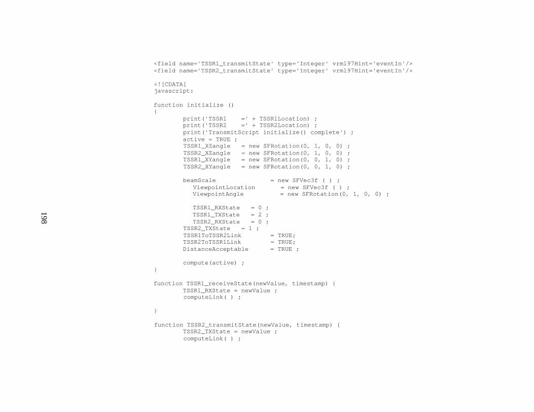
198
<field name='TSSR1_transmitState' type='Integer' vrml97Hint='eventIn'/> <field name='TSSR2_transmitState' type='Integer' vrml97Hint='eventIn'/> <
199
} function TSSR2_receiveState(newValue, timestamp) { TSSR2_RXState = newValue ; computeLink( ) ; } function TSSR1_transmitState(newValue, timestamp) { TSSR1_TXState = newValue ; computeLink( ) ; } function computeLink( ) { if ((TSSR2_TXState ==2) && (DistanceAcceptable)) { beamLengthLink2 = distance - 2 ;
if (TSSR1_RXState == 2) { TSSR2ToTSSR1Link = TRUE ; } else { TSSR2ToTSSR1Link = FALSE ;
} } else if ((TSSR2_TXState < 2) && (DistanceAcceptable)) { beamLengthLink2 = 5 ; TSSR2ToTSSR1Link = FALSE ; } if ((TSSR1_TXState ==2) && (DistanceAcceptable)) { beamLengthLink1 = distance - 2 ; if (TSSR2_RXState == 2) { TSSR1ToTSSR2Link = TRUE ; } else { TSSR1ToTSSR2Link = FALSE ; } } else if ((TSSR1_TXState < 2) && (DistanceAcceptable)) { beamLengthLink1 = 5 ;

200
TSSR1ToTSSR2Link = FALSE ; } } function compute ( ) { computeDistance( ) ; computeXZangle( ); ViewpointLocation[0] = TSSR1Location[0] ; ViewpointLocation[1] = TSSR1Location[1] + 4; ViewpointLocation[2] = TSSR1Location[2] ; print('ViewpointLocation =' + ViewpointLocation) ; ViewpointAngle[3] = TSSR1_XZangle[3] - Math.PI/2; print('ViewpointAngle =' + ViewpointAngle) ; computeXYangle( ) ; }
function computeDistance( ) { print('TSSR1 =' + TSSR1Location) ; print('TSSR2 =' + TSSR2Location) ; deltaX = (TSSR2Location[0] - TSSR1Location[0]) ;
deltaY = (TSSR2Location[1] - TSSR1Location[1]) ; deltaZ = (TSSR2Location[2] - TSSR1Location[2]) ; distanceSquared = deltaX * deltaX + deltaY * deltaY + deltaZ * deltaZ ; print('Distance Squared =' + distanceSquared) ; distance = Math.sqrt(distanceSquared) ; print('Distance =' + distance) ; beamScale[0] = distance/10; beamScale[1] = 5; beamScale[2] = 5; print('BeamScale =' + beamScale) ; if (distance > 5000/.6) { DistanceAcceptable = FALSE; beamLength = 5000; } else { DistanceAcceptable = TRUE ;

201
} } function computeXZangle( ) { if (deltaZ == 0) { deltaZ = .00000001 ; } angle = Math.atan(deltaX/deltaZ) ; if (deltaZ < 0) { TSSR1_XZangle[3] = angle + Math.PI/2; } else { TSSR1_XZangle[3] = angle - Math.PI/2; } TSSR2_XZangle[3] = TSSR1_XZangle[3] + Math.PI;
print('Angle =' + TSSR1_XZangle[3]) ; print('Angle2 =' + TSSR2_XZangle[3]) ; }
function computeXYangle( ) { angle = Math.asin(deltaY/distance) ; TSSR1_XYangle[3] = angle ; TSSR2_XYangle[3] = - TSSR1_XYangle[3]; print('AngleXY =' + TSSR1_XYangle[3]) ; print('Angle2XY =' + TSSR2_XYangle[3]) ; } ]]> </Script> </Group> <ROUTE fromNode='CalculateAngleScript' fromField='TSSR1_XZangle' toNode='TSSR1_TRANSFORM' toField='rotation'/> <ROUTE fromNode='CalculateAngleScript' fromField='TSSR2_XZangle' toNode='TSSR2_TRANSFORM' toField='rotation'/>
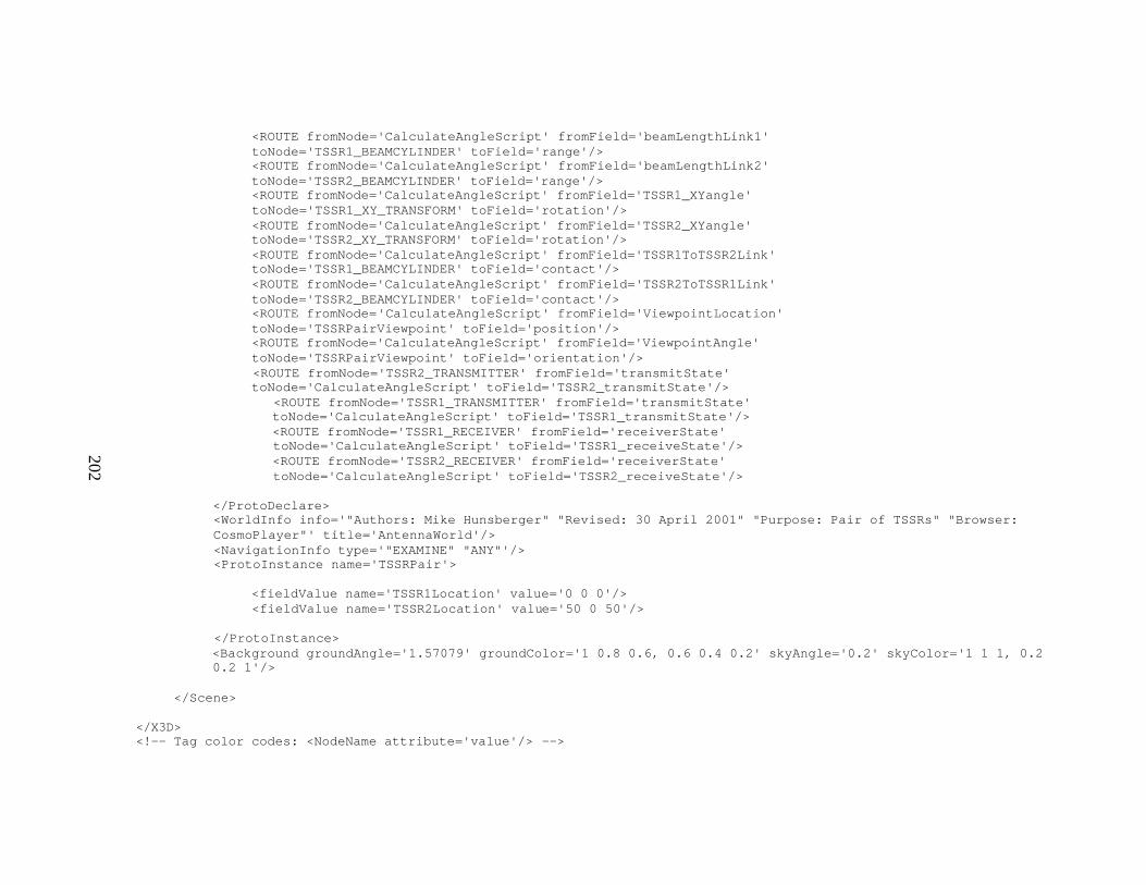
202
<ROUTE fromNode='CalculateAngleScript' fromField='beamLengthLink1' toNode='TSSR1_BEAMCYLINDER' toField='range'/> <ROUTE fromNode='CalculateAngleScript' fromField='beamLengthLink2' toNode='TSSR2_BEAMCYLINDER' toField='range'/> <ROUTE fromNode='CalculateAngleScript' fromField='TSSR1_XYangle' toNode='TSSR1_XY_TRANSFORM' toField='rotation'/> <ROUTE fromNode='CalculateAngleScript' fromField='TSSR2_XYangle' toNode='TSSR2_XY_TRANSFORM' toField='rotation'/> <ROUTE fromNode='CalculateAngleScript' fromField='TSSR1ToTSSR2Link' toNode='TSSR1_BEAMCYLINDER' toField='contact'/> <ROUTE fromNode='CalculateAngleScript' fromField='TSSR2ToTSSR1Link' toNode='TSSR2_BEAMCYLINDER' toField='contact'/> <ROUTE fromNode='CalculateAngleScript' fromField='ViewpointLocation' toNode='TSSRPairViewpoint' toField='position'/> <ROUTE fromNode='CalculateAngleScript' fromField='ViewpointAngle' toNode='TSSRPairViewpoint' toField='orientation'/> <ROUTE fromNode='TSSR2_TRANSMITTER' fromField='transmitState' toNode='CalculateAngleScript' toField='TSSR2_transmitState'/>
<ROUTE fromNode='TSSR1_TRANSMITTER' fromField='transmitState' toNode='CalculateAngleScript' toField='TSSR1_transmitState'/> <ROUTE fromNode='TSSR1_RECEIVER' fromField='receiverState' toNode='CalculateAngleScript' toField='TSSR1_receiveState'/> <ROUTE fromNode='TSSR2_RECEIVER' fromField='receiverState' toNode='CalculateAngleScript' toField='TSSR2_receiveState'/>
</ProtoDeclare> <WorldInfo info='"Authors: Mike Hunsberger" "Revised: 30 April 2001" "Purpose: Pair of TSSRs" "Browser: CosmoPlayer"' title='AntennaWorld'/> <NavigationInfo type='"EXAMINE" "ANY"'/> <ProtoInstance name='TSSRPair'> <fieldValue name='TSSR1Location' value='0 0 0'/> <fieldValue name='TSSR2Location' value='50 0 50'/> </ProtoInstance> <Background groundAngle='1.57079' groundColor='1 0.8 0.6, 0.6 0.4 0.2' skyAngle='0.2' skyColor='1 1 1, 0.2 0.2 1'/> </Scene> </X3D> <!-- Tag color codes: <NodeName attribute='value'/> -->

203
H. COMMPDUGENERATOR JAVA CODE LISTING
import mil.navy.nps.dis.*; import mil.navy.nps.disEnumerations.*; import mil.navy.nps.testing.*; // for MulticastPduSender import mil.navy.nps.util.*; import java.text.*; import java.io.*; import java.lang.*; import java.net.*;
import java.util.*; /** * * Generates default packets for radio family visualizations.
* * Authors: Mike Hunsberger * Start Date: 7 June 2001 * Revised: 14 June 2001 * Description: Generates DIS-JAVA-VRML transmitter and receiver Pdus for point * to point communications systems to to drive signals visualizations. * * *<dt><b>Invocation:</b> *<dd> java CommPduGenerator * * *<P>
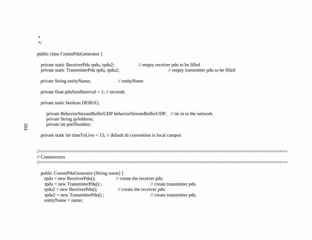
204
* */ public class CommPduGenerator { private static ReceiverPdu rpdu, rpdu2; // empty receiver pdu to be filled private static TransmitterPdu tpdu, tpdu2; // empty transmitter pdu to be filled private String entityName; // entityName private float pduSendInterval = 1; // seconds private static boolean DEBUG;
private BehaviorStreamBufferUDP behaviorStreamBufferUDP; // tie in to the network private String ipAddress; private int portNumber;
private static int timeToLive = 15; // default ttl convention is local campus //============================================================================================= // Constructors //============================================================================================= public CommPduGenerator (String name) { rpdu = new ReceiverPdu(); // create the receiver pdu tpdu = new TransmitterPdu() ; // create transmitter pdu rpdu2 = new ReceiverPdu(); // create the receiver pdu tpdu2 = new TransmitterPdu() ; // create transmitter pdu entityName = name;
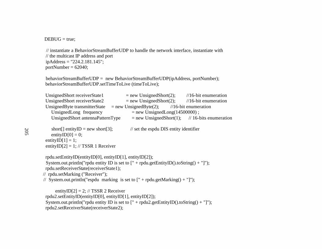
205
DEBUG = true; // instantiate a BehaviorStreamBufferUDP to handle the network interface, instantiate with // the multicast IP address and port ipAddress = "224.2.181.145"; portNumber = 62040; behaviorStreamBufferUDP = new BehaviorStreamBufferUDP(ipAddress, portNumber); behaviorStreamBufferUDP.setTimeToLive (timeToLive); UnsignedShort receiverState1 = new UnsignedShort(2); //16-bit enumeration UnsignedShort receiverState2 = new UnsignedShort(2); //16-bit enumeration UnsignedByte transmitterState = new UnsignedByte(2); //16-bit enumeration
UnsignedLong frequency = new UnsignedLong(14500000) ; UnsignedShort antennaPatternType = new UnsignedShort(1); // 16-bits enumeration short[] entityID = new short[3]; // set the espdu DIS entity identifier entityID[0] = 0;
entityID[1] = 1; entityID[2] = 1; // TSSR 1 Receiver rpdu.setEntityID(entityID[0], entityID[1], entityID[2]); System.out.println("rpdu entity ID is set to [" + rpdu.getEntityID().toString() + "]"); rpdu.setReceiverState(receiverState1); // rpdu.setMarking ("Receiver"); // System.out.println("espdu marking is set to [" + rpdu.getMarking() + "]"); entityID[2] = 2; // TSSR 2 Receiver rpdu2.setEntityID(entityID[0], entityID[1], entityID[2]); System.out.println("rpdu entity ID is set to [" + rpdu2.getEntityID().toString() + "]"); rpdu2.setReceiverState(receiverState2);
206
// rpdu.setMarking ("Receiver"); // System.out.println("espdu marking is set to [" + rpdu.getMarking() + "]"); short[] transmitterEntityID = new short[3]; // set the espdu DIS entity identifier transmitterEntityID[0] = 0; transmitterEntityID[1] = 1; transmitterEntityID[2] = 5; // TSSR 2 Transmitter tpdu.setEntityID(transmitterEntityID[0], transmitterEntityID[1], transmitterEntityID[2]); System.out.println("tpdu entity ID is set to [" + tpdu.getEntityID().toString() + "]"); tpdu.setFrequency(frequency) ; tpdu.setTransmitState(transmitterState) ; tpdu.setAntennaPatternType(antennaPatternType) ;
transmitterEntityID[2] = 6; // TSSR 2 Transmitter tpdu2.setEntityID(transmitterEntityID[0], transmitterEntityID[1], transmitterEntityID[2]); System.out.println("tpdu entity ID is set to [" + tpdu2.getEntityID().toString() + "]"); tpdu2.setFrequency(frequency) ;
tpdu2.setTransmitState(transmitterState) ; tpdu2.setAntennaPatternType(antennaPatternType) ; } // end constructor //============================================================================================= // Utility Methods //============================================================================================= public void debug(String message){ if(DEBUG){ System.out.println(message); } // end if

207
} // end debug private void send( ) { while (true) { UnsignedShort receiverState = new UnsignedShort(1); rpdu.setReceiverState(receiverState) ; rpdu2.setReceiverState(receiverState) ; UnsignedByte transmitterState = new UnsignedByte(1); tpdu.setTransmitState(transmitterState) ; tpdu2.setTransmitState(transmitterState) ; for (int i = 0; i < 10; i++) { rpdu.makeTimestampCurrent();
behaviorStreamBufferUDP.sendPdu(rpdu, ipAddress, portNumber); rpdu2.makeTimestampCurrent(); behaviorStreamBufferUDP.sendPdu(rpdu2, ipAddress, portNumber); System.out.println("Sent PDU") ; tpdu.makeTimestampCurrent();
behaviorStreamBufferUDP.sendPdu(tpdu, ipAddress, portNumber); tpdu2.makeTimestampCurrent(); behaviorStreamBufferUDP.sendPdu(tpdu2, ipAddress, portNumber); System.out.println("Sent Transmitter PDU") ; try{ Thread.sleep(500); } // end try catch (InterruptedException ie){} } receiverState = new UnsignedShort(2); rpdu.setReceiverState(receiverState) ; rpdu2.setReceiverState(receiverState) ; transmitterState = new UnsignedByte(2);

208
tpdu.setTransmitState(transmitterState) ; tpdu2.setTransmitState(transmitterState) ; for (int i = 0; i < 10; i++) { rpdu.makeTimestampCurrent(); behaviorStreamBufferUDP.sendPdu(rpdu, ipAddress, portNumber); rpdu2.makeTimestampCurrent(); behaviorStreamBufferUDP.sendPdu(rpdu2, ipAddress, portNumber); System.out.println("Sent PDU") ; tpdu.makeTimestampCurrent(); behaviorStreamBufferUDP.sendPdu(tpdu, ipAddress, portNumber); tpdu2.makeTimestampCurrent(); behaviorStreamBufferUDP.sendPdu(tpdu2, ipAddress, portNumber); System.out.println("Sent Transmitter PDU") ;
try{ Thread.sleep(500); } // end try catch (InterruptedException ie){} }
receiverState = new UnsignedShort(0); rpdu.setReceiverState(receiverState) ; rpdu2.setReceiverState(receiverState) ; transmitterState = new UnsignedByte(0); tpdu.setTransmitState(transmitterState) ; tpdu2.setTransmitState(transmitterState) ; for (int i = 0; i < 5; i++) { rpdu.makeTimestampCurrent(); behaviorStreamBufferUDP.sendPdu(rpdu, ipAddress, portNumber); rpdu2.makeTimestampCurrent(); behaviorStreamBufferUDP.sendPdu(rpdu2, ipAddress, portNumber); System.out.println("Sent PDU") ; tpdu.makeTimestampCurrent();

209
behaviorStreamBufferUDP.sendPdu(tpdu, ipAddress, portNumber); tpdu2.makeTimestampCurrent(); behaviorStreamBufferUDP.sendPdu(tpdu2, ipAddress, portNumber); System.out.println("Sent Transmitter PDU") ; try{ Thread.sleep(500); } // end try catch (InterruptedException ie){} } } }
//============================================================================================= // Main //============================================================================================= public static void main(String[] args){ boolean ttlMatch = false; boolean rtpMatch = false; CommPduGenerator communicator = new CommPduGenerator("Comm1"); // WorldCoordinate startPos = new WorldCoordinate(5.0, 3.0, 2.0); // create startPos

210
// receiver.rpdu.setEntityLocation(startPos); // set start Pos communicator.rpdu.setRtpHeaderEnabled(rtpMatch); communicator.tpdu.setRtpHeaderEnabled(rtpMatch) ; communicator.rpdu2.setRtpHeaderEnabled(rtpMatch); communicator.tpdu2.setRtpHeaderEnabled(rtpMatch) ; while (true) { communicator.send( ) ; try{ Thread.sleep(500); } // end try catch (InterruptedException ie){} } // end while
} // end main } // end class

211

212
APPENDIX F. TRC-170 TROPOSPHERIC SCATTER MICROWAVE RADIO TERMINAL PROTOTYPES
A. TRC-170 TROPOSPHERIC SCATTER MICROWAVE RADIO TERMINAL MODELS
This appendix contains code for the TRC-170 Tropospheric Scatter Microwave Radio models that are used throughout this thesis. They are
available at:
http://web.nps.navy.mil/~brutzman/vrml/examples/NpsMilitaryModels/CommunicationsAndSensors/TRC-170/chapter.html
This appendix contains the following files of X3D Code:
TRC-170Dish TRC-170Tripod TRC-170
TRC-170PairPrototype TRC-170PairExample

213
B. TRC-170 TROPOSPHERIC SCATTER MICROWAVE RADIO TERMINAL DISH
<?xml version="1.0" encoding="UTF-8"?> <!DOCTYPE X3D PUBLIC "http://www.web3D.org/TaskGroups/x3d/translation/x3d-compact.dtd" "file://localhost/C:/www.web3D.org/TaskGroups/x3d/translation/x3d-compact.dtd"> <X3D> <Header> <meta name='filename' content='TRC170-Dish.xml'/> <meta name='author' content='Mike Hunsberger'/> <meta name='created' content='7 May 2001'/> <meta name='revised' content='17 May 2001'/> <meta name='description' content='Dish of TRC-170 long-range SHF communication system. It operates in 3
modes: Direct point-to-point link (< 30 miles); Tropospheric shot (up to 100 or 150 miles, depending on system version); Defraction shot over an a terrain feature or object in the path ( < 50 miles).'/> <meta name='url' content='http://web.nps.navy.mil/~brutzman/vrml/NpsMilitaryModels/CommunicationsAndSensors/TRC170/TRC170-
Body.xml'/>
<meta name='generator' content='X3D-Edit, http://www.web3D.org/TaskGroups/x3d/translation/README.X3D-Edit.html'/> </Header> <Scene> <NavigationInfo type='"EXAMINE", "ANY"'/> <Background groundAngle='1.57079' groundColor='1 0.8 0.6, 0.6 0.4 0.2' skyAngle='0.2' skyColor='1 1 1, 0.2 0.2 1'/> <Group DEF='TRC170Body'> <Transform> <Shape> <Extrusion beginCap='false' convex='false' crossSection='1 0, .866 .5, .707 .707, .5 .866, 0 1, -.5 .866, -.707 .707, -.866 .5, -1 0, -.866 -.5, -.707 -.707, -.5 -.866 0 -1, .5 -.866,.707 -.707, .866 -.5, 1 0'
214
endCap='false' scale='.001 .001, 1.5 1.5' solid='false' spine='0 0 0, .15 0 0'/> <Appearance DEF='DarkGreen'> <Material diffuseColor='.1 .5 .1'/> </Appearance> </Shape> </Transform> <Group DEF='Columns'> <Transform rotation='0 0 1 1.57' translation='.5 0 .35'> <Shape DEF='column'> <Cylinder height='1' radius='.05'/>
<Appearance> <Material diffuseColor='.2 .2 .2'/> </Appearance>
</Shape> </Transform> <Transform rotation='0 0 1 1.57' translation='.5 0 -.35'> <Shape USE='column'/> </Transform> <Transform rotation='0 0 1 1.57' translation='.5 .35 0'> <Shape USE='column'/> </Transform> <Transform rotation='0 0 1 1.57' translation='.5 -.35 0'> <Shape USE='column'/> </Transform>

215
</Group> <Group> <Transform translation='1 0 0'> <Shape> <Box size='.1 .05 .7'/> <Appearance> <Material diffuseColor='.2 .2 .2'/> </Appearance> </Shape> </Transform>
<Transform translation='1 0 0'> <Shape> <Box size='.1 .7 .05'/> <Appearance>
<Material diffuseColor='.2 .2 .2'/> </Appearance> </Shape> </Transform> <Transform translation='.9 0 0'> <Shape> <Sphere radius='.1'/> <Appearance USE='DarkGreen'/> </Shape> </Transform>
216
</Group> </Group> </Scene> </X3D> <!-- Tag color codes: <NodeName attribute='value'/> -->

217
C. TRC-170 TROPOSPHERIC SCATTER MICROWAVE RADIO TERMINAL TRIPOD
<?xml version="1.0" encoding="UTF-8"?> <!DOCTYPE X3D PUBLIC "http://www.web3D.org/TaskGroups/x3d/translation/x3d-compact.dtd" "file://localhost/C:/www.web3D.org/TaskGroups/x3d/translation/x3d-compact.dtd"> <X3D> <Header> <meta name='filename' content='TRC170-Body.xml'/> <meta name='author' content='Mike Hunsberger'/> <meta name='created' content='7 May 2001'/> <meta name='revised' content='12 May 2001'/> <meta name='description' content='Body of and dish of TRC-170. A TRC-170 is a long-range SHF
communication system. It operates in 3 modes. 1)Direct point-to-point link (< 30 miles). 2) Tropospheric shot (up to 100 or 150 miles, depending on system version). 3) Defraction shot over an a terrain feature or object in the path ( < 50 miles).'/> <meta name='url' content='http://web.nps.navy.mil/~brutzman/vrml/NpsMilitaryModels/CommunicationsAndSensors/TRC170/TRC170-
Body.xml'/> <meta name='generator' content='X3D-Edit, http://www.web3D.org/TaskGroups/x3d/translation/README.X3D-Edit.html'/> </Header> <Scene> <NavigationInfo type='"EXAMINE", "ANY"'/> <Background groundAngle='1.57079' groundColor='1 0.8 0.6, 0.6 0.4 0.2' skyAngle='0.2' skyColor='1 1 1, 0.2 0.2 1'/> <Group DEF='TSSRBody'> <Transform> <Shape> <Extrusion beginCap='false' convex='false' crossSection='1 0, .866 .5, .707 .707, .5 .866, 0 1, -.5 .866, -.707 .707, -.866 .5, -1 0, -.866 -.5,

218
-.707 -.707, -.5 -.866 0 -1, .5 -.866,.707 -.707, .866 -.5, 1 0' endCap='false' scale='.001 .001, 1.5 1.5' solid='false' spine='0 0 0, .15 0 0'/> <Appearance DEF='DarkGreen'> <Material diffuseColor='.1 .5 .1'/> </Appearance> </Shape> </Transform> <Group DEF='Columns'> <Transform rotation='0 0 1 1.57' translation='.5 0 .35'> <Shape DEF='column'>
<Cylinder height='1' radius='.05'/> <Appearance> <Material diffuseColor='.2 .2 .2'/> </Appearance>
</Shape> </Transform> <Transform rotation='0 0 1 1.57' translation='.5 0 -.35'> <Shape USE='column'/> </Transform> <Transform rotation='0 0 1 1.57' translation='.5 .35 0'> <Shape USE='column'/> </Transform> <Transform rotation='0 0 1 1.57' translation='.5 -.35 0'> <Shape USE='column'/>

219
</Transform> </Group> <Group> <Transform translation='1 0 0'> <Shape> <Box size='.1 .05 .7'/> <Appearance> <Material diffuseColor='.2 .2 .2'/> </Appearance> </Shape>
</Transform> <Transform translation='1 0 0'> <Shape> <Box size='.1 .7 .05'/>
<Appearance> <Material diffuseColor='.2 .2 .2'/> </Appearance> </Shape> </Transform> <Transform translation='.9 0 0'> <Shape> <Sphere radius='.1'/> <Appearance USE='DarkGreen'/> </Shape>
220
</Transform> </Group> </Group> </Scene> </X3D> <!-- Tag color codes: <NodeName attribute='value'/> -->

221
D. TRC-170 TROPOSPHERIC SCATTER MICROWAVE RADIO TERMINAL
<?xml version="1.0" encoding="UTF-8"?> <!DOCTYPE X3D PUBLIC "http://www.web3D.org/TaskGroups/x3d/translation/x3d-compact.dtd" "file://localhost/C:/www.web3D.org/TaskGroups/x3d/translation/x3d-compact.dtd"> <X3D> <Header> <meta name='filename' content='TRC170.xml'/> <meta name='author' content='Mike Hunsberger'/> <meta name='created' content='17 May 2001'/> <meta name='revised' content='17 May 2001'/> <meta name='description' content='A TRC-170 is a long-range SHF communication system. It operates in 3
modes: Direct point-to-point link (< 30 miles); Tropospheric shot (up to 100 or 150 miles, depending on system version); Defraction shot over an a terrain feature or object in the path ( < 50 miles).'/> <meta name='url'
content='http://web.nps.navy.mil/~brutzman/vrml/NpsMilitaryModels/CommunicationsAndSensors/TRC170/TRC170- Tripod.xml'/>
<meta name='generator' content='X3D-Edit, http://www.web3D.org/TaskGroups/x3d/translation/README.X3D-Edit.html'/> </Header> <Scene> <NavigationInfo type='"EXAMINE", "ANY"'/> <Viewpoint description='TRC170 Stand' position='0 0 20'/> <Background groundAngle='1.57079' groundColor='1 0.8 0.6, 0.6 0.4 0.2' skyAngle='0.2' skyColor='1 1 1, 0.2 0.2 1'/> <Transform translation='0 -2.8 0'> <Inline url='"TRC170-Tripod.wrl" "TRC170-Tripod.xml" "../../CommunicationsAndSensors/TRC170/TRC170-Tripod.wrl" "../../CommunicationsAndSensors/TRC170/TRC170-Tripod.xml" "http://web.nps.navy.mil/~brutzman/vrml/NpsMilitaryModels/CommunicationsAndSensors/TRC170/TRC170-
Tripod.wrl"

222
"http://web.nps.navy.mil/~brutzman/vrml/NpsMilitaryModels/CommunicationsAndSensors/TRC170/TRC170-Tripod.xml"'/> </Transform> <Transform translation='1 2 0'> <Inline url='"TRC170-Dish.wrl" "TRC170-Dish.xml" "../../CommunicationsAndSensors/TRC170/TRC170-Dishwrl" "../../CommunicationsAndSensors/TRC170/TRC170-Dish.xml" "http://web.nps.navy.mil/~brutzman/vrml/NpsMilitaryModels/CommunicationsAndSensors/TRC170/TRC170-Dish.wrl" "http://web.nps.navy.mil/~brutzman/vrml/NpsMilitaryModels/CommunicationsAndSensors/TRC170/TRC170-Dish.xml"'/> </Transform> </Scene> </X3D>
<!-- Tag color codes: <NodeName attribute='value'/> -->

223
E. TRC-170 TROPOSPHERIC SCATTER MICROWAVE RADIO TERMINAL PAIR PROTOTYPE
<?xml version="1.0" encoding="UTF-8"?> <!DOCTYPE X3D PUBLIC "http://www.web3D.org/TaskGroups/x3d/translation/x3d-compact.dtd" "file://localhost/C:/www.web3D.org/TaskGroups/x3d/translation/x3d-compact.dtd"> <X3D> <Header> <meta name='filename' content='TRC170-PairPrototype.xml'/> <meta name='description' content='A Pair of TRC-170s. A TRC-170 is a long-range SHF communication system. It operates in 3 modes. 1)Direct point-to-point link (< 30 miles). 2) Tropospheric shot (up to 100 or 150, miles depending on system version). 3) Defraction shot over an a terrain feature or object in the path ( < 50 miles).'/>
<meta name='author' content='Mike Hunsberger'/> <meta name='created' content='8 May 2001'/> <meta name='revised' content='22 May 2001'/> <meta name='url'
content='http://web.nps.navy.mil/~brutzman/vrml/NpsMilitaryModels/CommunicationsAndSensors/TRC170/TRC170PairPrototype.xml'/>
<meta name='generator' content='X3D-Edit, http://www.web3D.org/TaskGroups/x3d/translation/README.X3D-Edit.html'/> </Header> <Scene> <ExternProtoDeclare name='BeamCylinder' nodeTypeHint='Transform' url='"../../CommunicationsAndSensors/Beam/BeamCylinderPrototype.wrl" "../../CommunicationsAndSensors/Beam/BeamCylinderPrototype.xml"'> <!-- contact: (communications) is transmitted signal in contact with receiver, or, (sensor) is a target return detected? --> <!-- range: distance in meters along x axis --> <!-- defaultRange: distance in meters, used until eventIn range sent --> <!-- beamHeight: meters across vertical y axis --> <!-- beamWidth: meters across horizontal z axis --> <!-- transparency: 1 = fully transparent, wireframe only -->
224
<!-- eventIn, eventOut and field semantics must be retained due to exposedField not being allowed in VRML 97 scripts (unfortunately) --> <field name='contact' type='Boolean' vrml97Hint='eventIn'/> <field name='range' type='Float' vrml97Hint='eventIn'/> <field name='defaultRange' type='Float' vrml97Hint='field'/> <field name='wireframe' type='Boolean' vrml97Hint='field'/> <field name='solid' type='Boolean' vrml97Hint='field'/> <field name='beamHeight' type='Float' vrml97Hint='field'/> <field name='beamWidth' type='Float' vrml97Hint='field'/> <field name='contactColor' type='Color' vrml97Hint='field'/> <field name='noContactColor' type='Color' vrml97Hint='field'/> <field name='transparency' type='Float' vrml97Hint='field'/> </ExternProtoDeclare> <ExternProtoDeclare name='BeamCone' nodeTypeHint='Transform' url='"../../CommunicationsAndSensors/Beam/BeamConePrototype.wrl" "../../CommunicationsAndSensors/Beam/BeamConePrototype.xml" "file:///C|/vrtp/demo/auv/BeamConePrototype.wrl" "file:///D|/vrtp/demo/auv/BeamConePrototype.wrl"
"http://web.nps.navy.mil/~brutzman/vrtp/demo/auv/BeamConePrototype.wrl" "http://www.web3D.org/WorkingGroups/vrtp/demo/auv/BeamConePrototype.wrl"'> <!-- contact: (communications) is transmitted signal in contact with receiver, or, (sensor) is a target return detected? --> <!-- range: distance in meters along x axis -->
<!-- defaultRange: distance in meters, used until eventIn range sent --> <!-- beamHeightDegrees: degrees across vertical y axis --> <!-- beamWidthDegrees: degrees across horizontal z axis --> <!-- transparency: 1 = fully transparent, wireframe only --> <!-- eventIn, eventOut and field semantics must be retained due to exposedField not being allowed in VRML 97 scripts (unfortunately) --> <field name='contact' type='Boolean' vrml97Hint='eventIn'/> <field name='range' type='Float' vrml97Hint='eventIn'/> <field name='defaultRange' type='Float' vrml97Hint='field'/> <field name='wireframe' type='Boolean' vrml97Hint='field'/> <field name='solid' type='Boolean' vrml97Hint='field'/> <field name='beamHeightDegrees' type='Float' vrml97Hint='field'/> <field name='beamWidthDegrees' type='Float' vrml97Hint='field'/> <field name='contactColor' type='Color' vrml97Hint='field'/> <field name='noContactColor' type='Color' vrml97Hint='field'/> <field name='transparency' type='Float' vrml97Hint='field'/> </ExternProtoDeclare>

225
<!-- ExternProtoDeclare definitions must be included verbatim --> <!-- PROTO consists of two TRC170 for long range (up to 100 mile) point-to-point communication. TRC170s can be used in 3 different settings. The first is a direct link of up to 30 miles. The second is a defraction setting over an obstruction in the path. The third is a tropospheric scatter shot of up to 100 miles in which the signal is bounced off the troposphere. This PROTO allows specification for the initial placement of each TSSR. It automatically calculates the correct angle to complete the link. --> <ProtoDeclare name='TRC170Pair'> <field name='TRC1Location' type='Vector3Float' value='1 1 1' IS='CalculateAngleScript.TRC1Location TRC1_TRANSFORM.translation' vrml97Hint='field'/> <field name='TRC2Location' type='Vector3Float' value='0 0 0' IS='CalculateAngleScript.TRC2Location TRC2_TRANSFORM.translation' vrml97Hint='field'/> <field name='OperatingMode' type='String' value='DIRECT' IS='CalculateAngleScript.OperatingMode' vrml97Hint='field'/> <Group> <Transform DEF='HighAboveXZTranslation'>
<Viewpoint DEF='HighAbove' description='High Above TRC170' orientation='1 0 0 -1.4' position='0 0 0'/> </Transform> <Viewpoint DEF='TRC1Viewpoint' description='TRC170 #1'/> <Viewpoint DEF='TRC2Viewpoint' description='TRC170 #2'/>
<LOD range='200000'> <!-- TRC 1 Two Transforms. One in the XZ plane, the second in the XY plane. Inlines for the TRC body, stand, and the dome pattern. --> <Transform DEF='TRC1_TRANSFORM' translation='-2 0 0'> <Transform DEF='TRC1_XY_TRANSFORM' translation='1 5 0'> <Inline DEF='TRCBody' url='"../../CommunicationsAndSensors/TRC170/TRC170-Dish.wrl" "../../CommunicationsAndSensors/TRC170/TRC170-Dish.xml" "TRC170-Dish.wrl" "TRC170-Dish.xml"'/> <Transform DEF='TRC1Cone' translation='2 0 0'> <Switch DEF='BeamSwitch' whichChoice='0'>

226
<Group> <ProtoInstance DEF='TRC1_BEAMCYLINDER' name='BeamCylinder'> <fieldValue name='defaultRange' value='10'/> <fieldValue name='range' value='10'/> <fieldValue name='beamHeight' value='1.5'/>
<fieldValue name='beamWidth' value='1.5'/> <fieldValue
name='transparency' value='0.2'/> <fieldValue name='wireframe' value='true'/> <fieldValue name='solid' value='true'/> <fieldValue name='contactColor' value='.3 .5 .5'/> <fieldValue

227
name='noContactColor' value='.8 .1 .1'/> </ProtoInstance> </Group> <Group> <ProtoInstance DEF='TRC1_BEAMCONE' name='BeamCone'> <fieldValue name='defaultRange' value='10'/>
<fieldValue name='beamHeightDegrees' value='2'/> <fieldValue name='beamWidthDegrees'
value='2'/> <fieldValue name='transparency' value='0.2'/> <fieldValue name='wireframe' value='true'/> <fieldValue name='solid' value='true'/> <fieldValue name='noContactColor' value='.8 .1

228
.1'/> <fieldValue name='contactColor' value='.3 .5 .5'/> </ProtoInstance> </Group> </Switch> </Transform> </Transform> <Transform>
<Inline DEF='TRCStand' url='"../../CommunicationsAndSensors/TRC170/TRC170-Tripod.wrl" "../../CommunicationsAndSensors/TRC170/TRC170-Tripod.xml" "TRC170-Tripod.wrl" "TRC170-Tripod.xml"'/> <LOD range='500'>
<Transform> <Viewpoint description='TRC170 Side View' position='0 5 40'/> </Transform> <Transform/> </LOD> </Transform> </Transform> <WorldInfo info='null node for no rendering when distant'/> <Script DEF='TransmitScript'>
229
<field name='transState' type='Integer' vrml97Hint='eventIn'/> <field name='size' type='Vector3Float' vrml97Hint='eventOut'/> <![CDATA[ javascript: function initialize () { size = new SFVec3f(100, 100, 100) ; print('TransmitScript initialize() complete') ; } // function name matches eventIn variable name ('hour') // hourValue captures the new value of the ROUTE hour event // minutes is just the current field value
function transState (newValue, timestamp) { transmitState = newValue ; if (transmitState == 3) { size = new SFVec3f(10, 10, 10) ;
} else { size = new SFVec3f(100, 100, 100) ; } print('size = ' + size) ; } ]]> </Script> </LOD> <LOD range='200000'> <!-- TRC 2 Two Transforms. One in the XZ plane, the second in the XY plane. Inlines for the TRC body, stand, and the dome pattern. --> <Transform DEF='TRC2_TRANSFORM' translation='-2 0 0'>

230
<Transform DEF='TRC2_XY_TRANSFORM' translation='1 5 0'> <Inline USE='TRCBody'/> <Transform DEF='TRC2Cone' translation='2 0 0'> <Switch DEF='BeamSwitch2' whichChoice='0'> <Group> <ProtoInstance DEF='TRC2_BEAMCYLINDER' name='BeamCylinder'> <fieldValue name='defaultRange'
value='10'/> <fieldValue name='range' value='10'/>
<fieldValue name='beamHeight' value='1.5'/> <fieldValue name='beamWidth' value='1.5'/> <fieldValue name='transparency' value='0.2'/> <fieldValue name='wireframe' value='true'/> <fieldValue name='solid'

231
value='true'/> <fieldValue name='contactColor' value='.3 .5 .5'/> <fieldValue name='noContactColor' value='.8 .1 .1'/> </ProtoInstance> </Group> <Group>
<ProtoInstance DEF='TRC2_BEAMCONE' name='BeamCone'> <fieldValue
name='defaultRange' value='10'/> <fieldValue name='beamHeightDegrees' value='2'/> <fieldValue name='beamWidthDegrees' value='2'/> <fieldValue name='transparency' value='0.2'/> <fieldValue name='wireframe' value='true'/>

232
<fieldValue name='solid' value='true'/> <fieldValue name='noContactColor' value='.8 .1 .1'/> <fieldValue name='contactColor' value='.3 .5 .5'/> </ProtoInstance>
</Group> </Switch> </Transform>
</Transform> <Transform> <Inline USE='TRCStand'/> <LOD range='500'> <Transform> <Viewpoint description='TRC170 Side View' position='0 5 40'/> </Transform> <Transform/> </LOD>

233
</Transform> </Transform> <Script DEF='TransmitScript2'> <field name='transState' type='Integer' vrml97Hint='eventIn'/> <field name='size' type='Vector3Float' vrml97Hint='eventOut'/> <![CDATA[ javascript: function initialize () { size = new SFVec3f(100, 100, 100) ; print('TransmitScript initialize() complete') ;
} // function name matches eventIn variable name ('hour') // hourValue captures the new value of the ROUTE hour event // minutes is just the current field value
function transState (newValue, timestamp) { transmitState = newValue ; if (transmitState == 3) { size = new SFVec3f(10, 10, 10) ; } else { size = new SFVec3f(100, 100, 100) ; } print('size = ' + size) ; } ]]> </Script> </LOD> <!-- This script is used to calculate the corresponding rotation angles so the TSSRs will
234
be pointed at each other --> <Script DEF='CalculateAngleScript'> <field name='TRC1Location' type='Vector3Float' vrml97Hint='field'/> <field name='TRC2Location' type='Vector3Float' vrml97Hint='field'/> <field name='OperatingMode' type='String' vrml97Hint='field'/> <field name='TRC1_XZangle' type='Rotation' vrml97Hint='eventOut'/> <field name='TRC2_XZangle' type='Rotation' vrml97Hint='eventOut'/> <field name='beamScale' type='Vector3Float' vrml97Hint='eventOut'/> <field name='TRC1_beamLength' type='Float' vrml97Hint='eventOut'/> <field name='TRC2_beamLength' type='Float' vrml97Hint='eventOut'/> <field name='TRC1_XYangle' type='Rotation' vrml97Hint='eventOut'/> <field name='TRC2_XYangle' type='Rotation' vrml97Hint='eventOut'/> <field name='LinkEstablished' type='Boolean' vrml97Hint='eventOut'/> <field name='TRC1_Viewpoint' type='Vector3Float' vrml97Hint='eventOut'/> <field name='TRC2_Viewpoint' type='Vector3Float' vrml97Hint='eventOut'/>
<field name='TRC1_ViewpointAngle' type='Rotation' vrml97Hint='eventOut'/> <field name='TRC2_ViewpointAngle' type='Rotation' vrml97Hint='eventOut'/> <field name='HighAboveViewpoint' type='Vector3Float' vrml97Hint='eventOut'/>
<field name='HighAboveTranslationAngle' type='Rotation' vrml97Hint='eventOut'/> <field name='WhichBeam' type='Integer' vrml97Hint='eventOut'/> <
235
XYangle = new SFRotation(0, 0, 1, 0) ; TRC1_ViewpointAngle = new SFRotation(0, 1, 0, 0) ; TRC2_ViewpointAngle = new SFRotation(0, 1, 0, 0) ; HighAboveViewpointAngle = new SFRotation(1, 0, 0, 0) ; HighAboveTranslationAngle = new SFRotation(0, 1, 0, 0) ; beamScale = new SFVec3f ( ) ; center = new SFVec3f ( ) ; TRC1_Viewpoint = new SFVec3f ( ) ; TRC2_Viewpoint = new SFVec3f ( ) ; HighAboveViewpoint = new SFVec3f ( ) ; LinkEstablished = TRUE; print('OperatingMode =' + OperatingMode) ; compute(active) ; }
function compute ( ) { if (OperatingMode == 'DIRECT') { WhichBeam = 0 ; computeDistance( ) ; computeXZangle( );
computeXYangle( ) ; } if (OperatingMode == 'TROPOSCATTER') { WhichBeam = 1 ; centerX = (TRC2Location[0] - TRC1Location[0])/2 ; centerZ = (TRC2Location[2] - TRC1Location[2])/2 ; XZDistance = Math.sqrt(centerX * centerX + centerZ * centerZ); center[0] = TRC1Location[0] + centerX; center[1] = 15000 ; // vertical height of troposphere center[2] = TRC1Location[2] + centerZ; print('TRC1 = ' + TRC1Location) ; print('center = ' + center) ; print('TRC2 = ' + TRC2Location) ; computeTropoDistance(TRC1Location, center) ;

236
computeTropoXZangle( ); computeTropoXYangle( ) ; TRC1_beamLength = tropoDistance-2; TRC1_XZangle = XZangle; TRC1_XYangle = XYangle; computeTropoDistance(TRC2Location, center) ; computeTropoXZangle( ); computeTropoXYangle( ) ; TRC2_beamLength = tropoDistance-2; TRC2_XZangle = XZangle; TRC2_XYangle = XYangle; } TRC1_Viewpoint[0] = TRC1Location[0] + Math.sin(TRC1_XZangle[3] - 1.57)*40; TRC1_Viewpoint[1] = TRC1Location[1] + 10; TRC1_Viewpoint[2] = TRC1Location[2] +Math.cos(TRC1_XZangle[3] - 1.57)*40; print('TRC1_Viewpoint '+ TRC1_Viewpoint) ;
TRC1_ViewpointAngle[3] = TRC1_XZangle[3] - 1.57 ; TRC2_Viewpoint[0] = TRC2Location[0] + Math.sin(TRC2_XZangle[3] - 1.57)*40 ; TRC2_Viewpoint[1] = TRC2Location[1] + 10; TRC2_Viewpoint[2] = TRC2Location[2] + Math.cos(TRC2_XZangle[3] - 1.57)*40; TRC2_ViewpointAngle[3] = TRC2_XZangle[3] - 1.57 ;
print('TRC2_Viewpoint '+ TRC2_Viewpoint) ; HighAboveViewpoint[0] = center[0] + Math.sin(TRC1_XZangle[3])*3000 ; HighAboveViewpoint[1] = center[1] + 5000; HighAboveViewpoint[2] = center[2] + Math.cos(TRC1_XZangle[3])*3000 ; print('HighAboveViewpoint '+ HighAboveViewpoint) ; // HighAboveViewpointAngle[3] = Math.cos(TRC1_XZangle[3]) ; HighAboveTranslationAngle[3] = TRC1_XZangle[3] ; //print('HighAboveTranslationle '+ HighAboveViewpointAngle) ; print('HighAboveXZTranslationAngle '+HighAboveTranslationAngle) ; } function computeTropoDistance(loc1, loc2 ) { tropoDeltaX = (loc2[0] - loc1[0]) ;

237
tropoDeltaY = (loc2[1] - loc1[1]) ; tropoDeltaZ = (loc2[2] - loc1[2]) ; tropoDistanceSquared = tropoDeltaX * tropoDeltaX + tropoDeltaY * tropoDeltaY +
tropoDeltaZ * tropoDeltaZ ; print('Distance Squared =' + tropoDistanceSquared) ; tropoDistance = Math.sqrt(tropoDistanceSquared) ; print('Distance =' + tropoDistance) ; if (XZDistance > 100/.6*1000) { LinkEstablished = FALSE; //TRC1_beamLength = 5000 ; //TRC2_beamLength = 5000 ; } } function computeTropoXZangle( ) { if (tropoDeltaZ == 0) {
tropoDeltaZ = .00000001 ; } angle = Math.atan(tropoDeltaX/tropoDeltaZ) ; if (tropoDeltaZ < 0) { XZangle[3] = angle + Math.PI/2;
} else { XZangle[3] = angle - Math.PI/2; } print('Angle =' + XZangle[3]) ; //print('Angle2 =' + TRC2_XZangle[3]) ; } function computeTropoXYangle( ) { print('tropoDeltaY =' + tropoDeltaY); angle = Math.asin(tropoDeltaY/tropoDistance) ; XYangle[3] = angle ; //XYangle[3] = - TRC1_XYangle[3]; print('AngleXY =' +XYangle[3]) ; //print('Angle2XY =' + TRC2_XYangle[3]) ;

238
} function computeDistance( ) { print('TRC1 =' + TRC1Location) ; print('TRC2 =' + TRC2Location) ; deltaX = (TRC2Location[0] - TRC1Location[0]) ; deltaY = (TRC2Location[1] - TRC1Location[1]) ; deltaZ = (TRC2Location[2] - TRC1Location[2]) ; distanceSquared = deltaX * deltaX + deltaY * deltaY + deltaZ * deltaZ ; print('Distance Squared =' + distanceSquared) ; distance = Math.sqrt(distanceSquared) ; print('Distance =' + distance) ; beamScale[0] = distance/10; beamScale[1] = 10; beamScale[2] = 10; print('BeamScale =' + beamScale) ;
TRC1_beamLength = distance -2; TRC2_beamLength = distance -2; if (distance > 5/.6*1000) { LinkEstablished = FALSE; TRC1_beamLength = 5000/.6 ; TRC2_beamLength = 5000/.6 ;
} } function computeXZangle( ) { if (deltaZ == 0) { deltaZ = .00000001 ; } angle = Math.atan(deltaX/deltaZ) ; if (deltaZ < 0) { TRC1_XZangle[3] = angle + Math.PI/2; } else { TRC1_XZangle[3] = angle - Math.PI/2; } TRC2_XZangle[3] = TRC1_XZangle[3] + Math.PI;

239
print('Angle =' + TRC1_XZangle[3]) ; print('Angle2 =' + TRC2_XZangle[3]) ; } function computeXYangle( ) { angle = Math.asin(deltaY/distance) ; TRC1_XYangle[3] = angle ; TRC2_XYangle[3] = - TRC1_XYangle[3]; print('AngleXY =' + TRC1_XYangle[3]) ; print('Angle2XY =' + TRC2_XYangle[3]) ; } ]]> </Script>
</Group> <ROUTE fromNode='CalculateAngleScript' fromField='TRC1_XZangle' toNode='TRC1_TRANSFORM' toField='rotation'/> <ROUTE fromNode='CalculateAngleScript' fromField='TRC2_XZangle' toNode='TRC2_TRANSFORM' toField='rotation'/>
<ROUTE fromNode='CalculateAngleScript' fromField='TRC1_beamLength' toNode='TRC1_BEAMCYLINDER' toField='range'/> <ROUTE fromNode='CalculateAngleScript' fromField='TRC1_beamLength' toNode='TRC1_BEAMCONE' toField='range'/> <ROUTE fromNode='CalculateAngleScript' fromField='TRC2_beamLength' toNode='TRC2_BEAMCYLINDER' toField='range'/> <ROUTE fromNode='CalculateAngleScript' fromField='TRC1_beamLength' toNode='TRC2_BEAMCONE' toField='range'/> <ROUTE fromNode='CalculateAngleScript' fromField='TRC1_XYangle' toNode='TRC1_XY_TRANSFORM' toField='rotation'/> <ROUTE fromNode='CalculateAngleScript' fromField='TRC2_XYangle' toNode='TRC2_XY_TRANSFORM' toField='rotation'/> <ROUTE fromNode='CalculateAngleScript' fromField='LinkEstablished' toNode='TRC1_BEAMCYLINDER' toField='contact'/> <ROUTE fromNode='CalculateAngleScript' fromField='LinkEstablished' toNode='TRC1_BEAMCONE' toField='contact'/> <ROUTE fromNode='CalculateAngleScript' fromField='LinkEstablished' toNode='TRC2_BEAMCYLINDER' toField='contact'/>

240
<ROUTE fromNode='CalculateAngleScript' fromField='LinkEstablished' toNode='TRC2_BEAMCONE' toField='contact'/> <ROUTE fromNode='CalculateAngleScript' fromField='TRC1_Viewpoint' toNode='TRC1Viewpoint' toField='position'/> <ROUTE fromNode='CalculateAngleScript' fromField='TRC2_Viewpoint' toNode='TRC2Viewpoint' toField='position'/> <ROUTE fromNode='CalculateAngleScript' fromField='TRC1_ViewpointAngle' toNode='TRC1Viewpoint' toField='orientation'/> <ROUTE fromNode='CalculateAngleScript' fromField='TRC2_ViewpointAngle' toNode='TRC2Viewpoint' toField='orientation'/> <ROUTE fromNode='CalculateAngleScript' fromField='HighAboveViewpoint' toNode='HighAboveXZTranslation' toField='translation'/> <ROUTE fromNode='CalculateAngleScript' fromField='HighAboveTranslationAngle' toNode='HighAboveXZTranslation' toField='rotation'/> <ROUTE fromNode='CalculateAngleScript' fromField='WhichBeam' toNode='BeamSwitch' toField='whichChoice'/> <ROUTE fromNode='CalculateAngleScript' fromField='WhichBeam' toNode='BeamSwitch2' toField='whichChoice'/>
</ProtoDeclare> <WorldInfo info='"Authors: Mike Hunsberger" "Revised: 30 April 2001" "Purpose: Pair of TSSRs" "Browser: CosmoPlayer"' title='AntennaWorld'/> <NavigationInfo type='"EXAMINE" "ANY"'/> <ProtoInstance name='TRC170Pair'>
<fieldValue name='TRC1Location' value='0 0 0'/> <fieldValue name='TRC2Location' value='-20000 0 -20000'/> <fieldValue name='OperatingMode' value='TROPOSCATTER'/> </ProtoInstance> <Background groundAngle='1.57079' groundColor='1 0.8 0.6, 0.6 0.4 0.2' skyAngle='0.2' skyColor='1 1 1, 0.2 0.2 1'/> </Scene> </X3D> <!-- Tag color codes: <NodeName attribute='value'/> -->

241
F. TRC-170 TROPOSPHERIC SCATTER MICROWAVE RADIO TERMINAL PAIR EXAMPLE
<?xml version="1.0" encoding="UTF-8"?> <!DOCTYPE X3D PUBLIC "http://www.web3D.org/TaskGroups/x3d/translation/x3d-compact.dtd" "file://localhost/C:/www.web3D.org/TaskGroups/x3d/translation/x3d-compact.dtd"> <X3D> <Header> <meta name='filename' content='TRC170-PairExample.xml'/> <meta name='description' content='Instantiatio of the TRC-170 Pair Prototype. A TRC-170 is a long-range SHF communication system. It operates in 3 modes. 1)Direct point-to-point link (< 30 miles). 2) Tropospheric shot (up to 100 or 150 miles, depending on system version). 3) Defraction shot over an a terrain feature or object in the path ( < 50 miles).'/> <meta name='author' content='Mike Hunsberger'/>
<meta name='created' content='7 May 2001'/> <meta name='revised' content='12 May 2001'/> <meta name='url' content='http://web.nps.navy.mil/~brutzman/vrml/NpsMilitaryModels/CommunicationsAndSensors/TRC170/TRC170- PairExample.xml'/>
<meta name='generator' content='X3D-Edit, http://www.web3D.org/TaskGroups/x3d/translation/README.X3D-Edit.html'/> </Header> <Scene> <!-- ExternProtoDeclare definitions must be included verbatim --> <ExternProtoDeclare name='TRC170Pair' url='"../../CommunicationsAndSensors/TRC170/TRC170-PairPrototype.wrl" "../../CommunicationsAndSensors/TRC170/TRC170-PairPrototype.xml"'> <field name='TRC1Location' type='Vector3Float' vrml97Hint='field'/> <field name='TRC2Location' type='Vector3Float' vrml97Hint='field'/> <field name='OperatingMode' type='String' vrml97Hint='field'/> </ExternProtoDeclare> <WorldInfo info='"Authors: Mike Hunsberger" "Revised: 30 April 2001" "Purpose: Pair of TSSRs" "Script: none" "Browser: CosmoPlayer"' title='AntennaWorld'/>

242
<NavigationInfo type='"EXAMINE" "ANY"'/> <Background groundAngle='1.57079' groundColor='1 0.8 0.6, 0.6 0.4 0.2' skyAngle='0.2' skyColor='1 1 1, 0.2 0.2 1'/> <ProtoInstance name='TRC170Pair'> <fieldValue name='TRC1Location' value='15000 0 15000'/> <fieldValue name='TRC2Location' value='0 0 0'/> <fieldValue name='OperatingMode' value='TROPOSCATTER'/> </ProtoInstance> </Scene> </X3D> <!-- Tag color codes: <NodeName attribute='value'/> -->
243
APPENDIX G. TERRAIN DEVELOPMENT CODE
A. INTRODUCTION
This section provides the code used to develop the 3D terrain models used in this thesis. The following MATLAB code is used to
process Digital Terrain Elevation Data and create 3D elevation grids. These files and the VRML output are available at
http://web.nps.navy.mil/~brutzman/vrml/examples/NpsMilitaryModels/Locations/CampPendletonCalifornia/_pages/page01.html
The MATLAB files are:
convertCampPendletonTerrainData.m CampPendletonColorMap.m CampPendletonColorDepths.m
printX3dHeader.m printX3dFooter.m

244
B. CONVERT CAMP PENDLETON TERRAIN DATA
% Filename: convertCampPendletonTerrainData.m % Author: Curt Blais (derived from convertBathymetryXyzFile.m by Don Brutzman) % Created: 7 April 2001 % Revised: 20 June 2001 % Description: Read gridded elevation data obtained from DTED files via MatLab. % Build X3D elevation grid. Create artificial bathymetry for bodies % of water. % Metadata: Camp Pendleton Level 1 Digital Terrain Elevation Data (DTED) % from National Imagery and Mapping Agency (NIMA) CD TCD-DTED128
% (NOTE: No network access is available to the original terrain % data at this time -- a meta tag will be provided when/if this % becomes available via network access) % % Invocation: cd
c:\www.web3D.org\TaskGroups\x3d\translation\examples\NpsMilitaryModels\Locations\CampPendletonCalifornia % convertCampPendletonTerrainData; % Output: CampPendletonOperatingAreasExample.xml % - - - - - - - - - - - - - - - - - - - - - - - - - - - - - - - - - - - - - % Note: The MatLab Mapping Toolkit manual states "A regular matrix map is one % in which columns of data run south to north, rows of data run west to % to east, and each matrix element represents the same angular step in % each direction, for all rows and columns." In fact, when you call the % matlab function setpostn on the map data read from the DTED CDROM, it % is apparent that ROWS are increasing from south to north, and COLUMNS % are increasing from west to east!
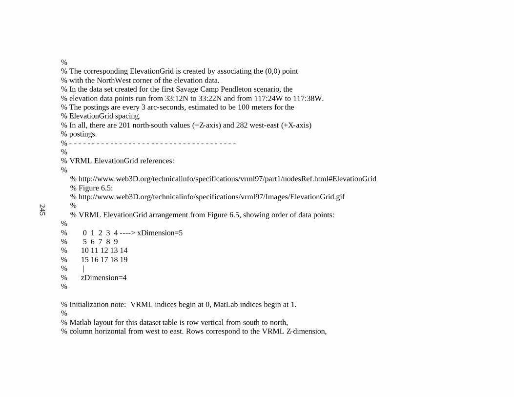
245
% % The corresponding ElevationGrid is created by associating the (0,0) point % with the NorthWest corner of the elevation data. % In the data set created for the first Savage Camp Pendleton scenario, the % elevation data points run from 33:12N to 33:22N and from 117:24W to 117:38W. % The postings are every 3 arc-seconds, estimated to be 100 meters for the % ElevationGrid spacing. % In all, there are 201 north-south values (+Z-axis) and 282 west-east (+X-axis) % postings. % - - - - - - - - - - - - - - - - - - - - - - - - - - - - - - - - - - - - - % % VRML ElevationGrid references: %
% http://www.web3D.org/technicalinfo/specifications/vrml97/part1/nodesRef.html#ElevationGrid % Figure 6.5: % http://www.web3D.org/technicalinfo/specifications/vrml97/Images/ElevationGrid.gif % % VRML ElevationGrid arrangement from Figure 6.5, showing order of data points:
% % 0 1 2 3 4 ----> xDimension=5 % 5 6 7 8 9 % 10 11 12 13 14 % 15 16 17 18 19 % | % zDimension=4 % % Initialization note: VRML indices begin at 0, MatLab indices begin at 1. % % Matlab layout for this dataset table is row vertical from south to north, % column horizontal from west to east. Rows correspond to the VRML Z-dimension,

246
% columns correspond to the VRML X-dimension: % % zDimension=maxLat % | % (maxLat, 1) ... (maxLat, maxLong) % | | % | | % | | % | | % (1, 1) ... (1, maxLong) -> xDimension=maxLong % % thus ElevationGrid xDimension maps to column longitudes, % and ElevationGrid zDimension maps to row latitudes.
% % Therefore, the order for filling in the ElevationGrid values is % first from (maxLat, 1) to (maxLat, maxLong) % [meaning inner loop is columns = longitudes] % then from (maxLat, 1) down to (1, 1)
% [meaning outer loop is rows = latitudes, in reverse order] % % (maxLat, 1) corresponds to 33:22N, 117:38W % (maxLat, maxLong) corresponds to 33:22N, 117:24W % (1 , 1) corresponds to 33:12N, 117:38W % (1 , maxLong) corresponds to 33:12N, 117:24W % - - - - - - - - - - - - - - - - - - - - - - - - - - - - - - - - - - - - - true = 1; false = 0; % load source terrain data read from the NIMA CD if ~exist('demdata')

247
disp('loading CampPendletonTerrainData.mat ...'); load('CampPendletonTerrainData.mat') % loads data into matrix 'demdata' else whos demdata; end; % set boundary values for selecting the portion of the data covering the scenario % area of interest minLatRow = 279; maxLatRow = 479; nRows = 201; minLongCol = 682; maxLongCol = 963; nCols = 282;
nDataPoints = nRows * nCols; disp (['Process ' num2str(nDataPoints) ' evenly spaced data points']); disp ([' in 3 arc-second lat- long locations ...']); fprintf ('\n');
latSpacing = 100; % meters, approximating 3 arc-seconds of latitude longSpacing = 100; % meters, approximating 3 arc-seconds of longitude % - - - - - - - - - - - - - - - - - - - - - - - - - - - - - - - - - - - - - disp('commencing to build CampPendletonOperatingAreasExample.xml ...'); fprintf ('\n'); fileElevation = fopen('CampPendletonOperatingAreasExample.xml', 'w'); % write out the front part of the XML file containing metadata and starting structure % for the scene graph (including NavigationInfo, Background, and Viewpoint nodes)

248
printX3dHeader (fileElevation, 'CampPendletonOperatingAreasExample.xml'); fprintf (fileElevation, ['xDimension="' num2str(nCols) '" ']); fprintf (fileElevation, ['zDimension="' num2str(nRows) '" ']); fprintf (fileElevation, ['xSpacing="' num2str(longSpacing) '" ']); fprintf (fileElevation, ['zSpacing="' num2str(latSpacing) '"\n']); fprintf (fileElevation, 'height="\n'); % create a matrix containing just the data of interest from the NIMA DTED file scenarioData(1:nRows,1:nCols) = demdata.map(minLatRow:maxLatRow,minLongCol:maxLongCol); % for elevation values equal to -1 (water), create artificial bathymetric values % (in meters) by interpolating between depth readings at the corners of the region % note: for the Camp Pendleton data, only the upper left and lower left corners
% are in the water -- the other corners have values from the terrain data files metersPerFoot = 0.3048; % conversion factor for feet to meters lowerLeftDepthFromMap = -2800; upperLeftDepthFromMap = -200; lowerLeftDepth = lowerLeftDepthFromMap*metersPerFoot;
upperLeftDepth = upperLeftDepthFromMap*metersPerFoot; upperRightElev = scenarioData(nRows, nCols); % not used in the rest of the program lowerRightElev = scenarioData(1 , nCols); % not used in the rest of the program % set the range of the bathymetry data (maximum depth, in meters) bathymetryRange = lowerLeftDepth - upperLeftDepth; % set a randomness factor to control the variability of the artificial bathymetry deviationFactor = 4.0; % set starting point for the corners in the elevation matrix scenarioData(1,1) = lowerLeftDepth; scenarioData(nRows,1) = upperLeftDepth;
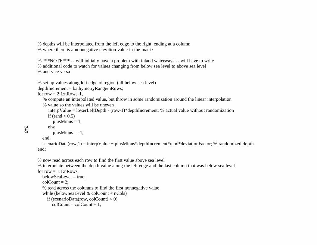
249
% depths will be interpolated from the left edge to the right, ending at a column % where there is a nonnegative elevation value in the matrix % ***NOTE*** -- will initially have a problem with inland waterways -- will have to write % additional code to watch for values changing from below sea level to above sea level % and vice versa % set up values along left edge of region (all below sea level) depthIncrement = bathymetryRange/nRows; for row = 2:1:nRows-1, % compute an interpolated value, but throw in some randomization around the linear interpolation % value so the values will be uneven
interpValue = lowerLeftDepth - (row-1)*depthIncrement; % actual value without randomization if (rand < 0.5) plusMinus = 1; else plusMinus = -1;
end; scenarioData(row,1) = interpValue + plusMinus*depthIncrement*rand*deviationFactor; % randomized depth end; % now read across each row to find the first value above sea level % interpolate between the depth value along the left edge and the last column that was below sea level for row = 1:1:nRows, belowSeaLevel = true; colCount = 2; % read across the columns to find the first nonnegative value while (belowSeaLevel & colCount < nCols) if (scenarioData(row, colCount) < 0) colCount = colCount + 1;

250
else belowSeaLevel = false; end; end; % reset colCount to last value read from the matrix that had depth less than 0 colCount = colCount - 1; % interpolate across the row from column 1 to column colCount % as before, throw in some randomness to make the surface more interesting if (colCount > 1) % otherwise, no values to interpolate between leftEdgeDepth = scenarioData(row,1); depthIncrement = leftEdgeDepth/colCount; for col = 2:1:colCount, % compute an interpolated value, but throw in some randomization around the linear interpolation
% value so the values will be uneven interpValue = leftEdgeDepth - (col-1)*depthIncrement; % actual value without randomization if (rand < 0.5) plusMinus = 1; else
plusMinus = -1; end; scenarioData(row,col) = interpValue + plusMinus*depthIncrement*rand*deviationFactor; % randomized depth end; % for col = 2:1:colCount end; % colCount > 1 end; % read the elevation values from the source data and write the values into the % ElevationGrid node for row = nRows:-1:1, for col = 1:1:nCols, % where the elevation is -1 (water), change to -100 to create greater spacing

251
% in the output file (precursor to substituting real bathymetry data or creating % synthetic data for this area) if (scenarioData(row,col) == -1) scenarioData(row,col) = -100; end; fprintf(fileElevation, '%5.0f',scenarioData(row,col) ); if (col < nCols - 1) fprintf(fileElevation, '\t'); if (mod(col,10) == 0) % output line feed after every 10 data points fprintf(fileElevation, '\n'); end; else % output extra line feed at the end of each row of data fprintf(fileElevation, '\n');
end; end; if (mod(row,10) == 0) %output extra line feed after every 10 rows fprintf(fileElevation, '\n'); end;
end; % add a ColorNode to the ElevationGrid fprintf (fileElevation, '"> \n'); % end height table, end ElevationGrid tag fprintf (fileElevation, ' <ColorNode color="\n'); % compute min and max values of terrain height data stored in the region of interest % these values can be used for interpolating colors in elevation color mapping bathymetryRange = min(min(scenarioData(1:nRows, 1:nCols))); elevationRange = max(max(scenarioData(1:nRows, 1:nCols))); % re-read the elevation values from the source data and write out corresponding % elevation color-map values into the ColorNode

252
for row = nRows:-1:1, for col = 1:1:nCols, if scenarioData(row,col) >= 0 % use elevation color mapping for terrain fprintf(fileElevation, CampPendletonColorMap(scenarioData(row,col), elevationRange)); else % use depth color mapping for bathymetry data fprintf(fileElevation, CampPendletonColorDepths(scenarioData(row,col), bathymetryRange)); end; if (col < nCols - 1) fprintf(fileElevation, '\t'); if (mod(col,10) == 0) % output line feed after every 10 data points fprintf(fileElevation, '\n');
end; else fprintf(fileElevation, '\n'); end; end; if (mod(row,10) == 0) %output extra line feed after every 10 rows
fprintf(fileElevation, '\n'); end; end; fprintf (fileElevation, '"/>\n'); % end ColorNode tag fprintf (fileElevation, ' </ElevationGrid>\n'); fprintf (fileElevation, ' </Shape>\n'); % write out the remainder of the XML file printX3dFooter (fileElevation, false); % close the input file fclose(fileElevation);

253
disp('elevation file generation complete.'); fprintf ('\n'); % - - - - - - - - - - - - - - - - - - - - - - - - - - - - - - - - - - - - - % in MatLab, output a picture of the selected elevation data mesh(demdata.map(minLatRow:maxLatRow, minLongCol:maxLongCol)); % - - - - - - - - - - - - - - - - - - - - - - - - - - - - - - - - - - - - - % the following shows file conversion calls for the exemplar file that built a % bathymetry scene for Fort Lauderdale data -- this remnant can be modified later % for reuse if the same actions are desired with the Camp Pendleton XML file
% disp ('XML to VRML translations'); % disp ('XML syntax checks: c:\xml\microsoft \xmlint *.xml'); %! c:\xml\microsoft \xmlint *.xml
% instant saxon not yet able to handle such large attributes % can convert 10..80 using X3D-Edit (which uses xalan) % keep the following commented until autotranslation capacity corrected %! c:\www.web3D.org\TaskGroups\x3d\translation\X3dToVrml97.bat FortLauderdaleDepthSelection % ! c:\www.web3D.org\TaskGroups\x3d\translation\X3dToVrml97.bat ElevationGridExample % ! c:\www.web3D.org\TaskGroups\x3d\translation\X3dToVrml97.bat FortLauderdaleDepths05m % ! c:\www.web3D.org\TaskGroups\x3d\translation\X3dToVrml97.bat FortLauderdaleDepths10m % ! c:\www.web3D.org\TaskGroups\x3d\translation\X3dToVrml97.bat FortLauderdaleDepths20m % ! c:\www.web3D.org\TaskGroups\x3d\translation\X3dToVrml97.bat FortLauderdaleDepths40m % ! c:\www.web3D.org\TaskGroups\x3d\translation\X3dToVrml97.bat FortLauderdaleDepths80m

254
%! mv FortLauderdaleDepthSelectionTranslated.wrl FortLauderdaleDepthSelection.wrl % ! mv ElevationGridExampleTranslated.wrl ElevationGridExample.wrl % ! mv FortLauderdaleDepths05mTranslated.wrl FortLauderdaleDepths05m.wrl % ! mv FortLauderdaleDepths10mTranslated.wrl FortLauderdaleDepths10m.wrl % ! mv FortLauderdaleDepths20mTranslated.wrl FortLauderdaleDepths20m.wrl % ! mv FortLauderdaleDepths40mTranslated.wrl FortLauderdaleDepths40m.wrl % ! mv FortLauderdaleDepths80mTranslated.wrl FortLauderdaleDepths80m.wrl %! c:\vrml\vorlon\vorlon *.wrl

255
C. CAMP PENDELTON COLOR MAP
% Filename: CampPendletonColorMap.m % Author: Curt Blais (adapted from sample by Don Brutzman) % Created: 11 April 2001 % Revised: 20 June 2001 % Description: Coloration of Camp Pendleton terrain based on photo images taken in Dec 2000. function rgbValue = colorValue (elevationInMeters, elevationRange); spacer = '\t';
foliage = 0.05; %abundance of greenery in higher elevations % some helpful color-value definitions available at % http://www.w3.org/TR/1998/REC-html40-19980424/types.html#idx-color
% The following sampled colors are from photographs by Jeff Weekley, Rolands and Associates, % taken at Camp Pendleton, Dec 2000 (red-green-blue values are between 0 and 255) % Sand 238 227 213-221 % 203 201 204 % Dunes 177 172 166 % 157 141 151 % Hillocks 161 175 184 % 170 190 191 % Hills % above Hiway 210 205 209 % 205 205 205 % Intermediate Bands of % Greenery 146 162 149
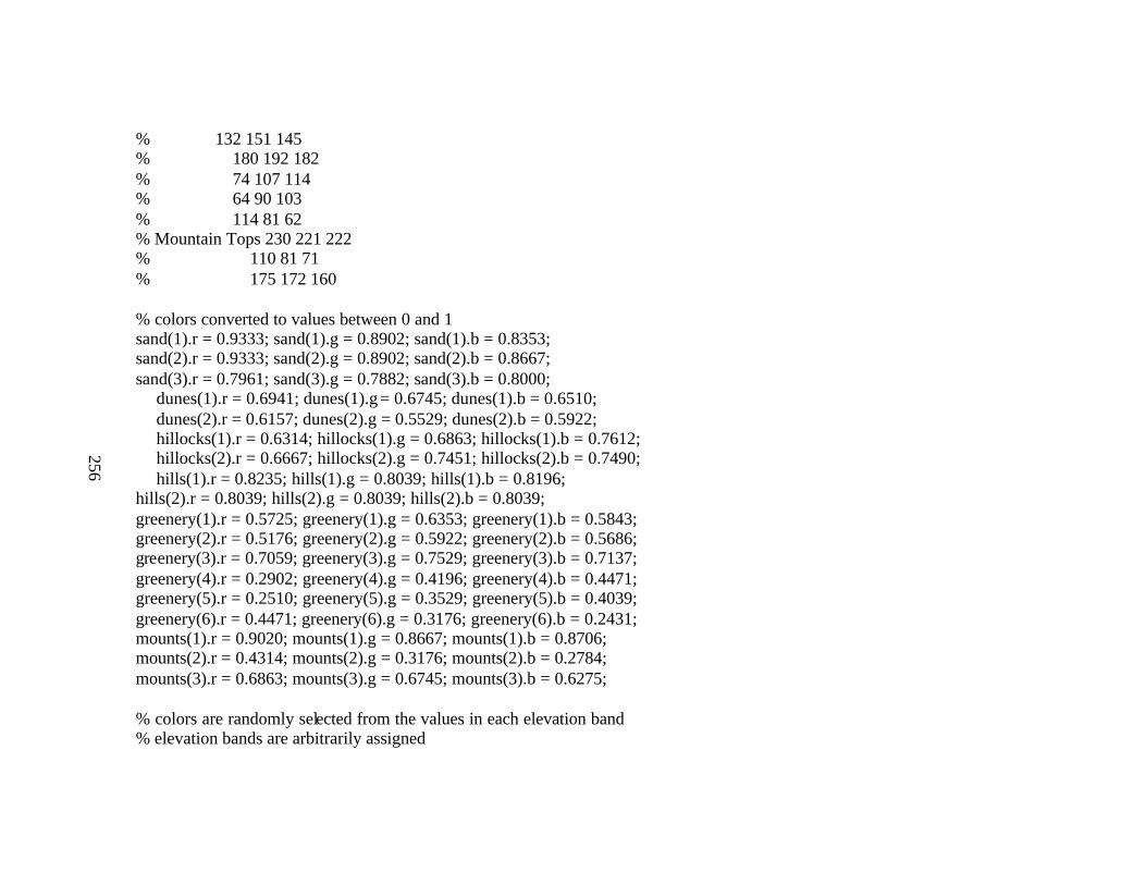
256
% 132 151 145 % 180 192 182 % 74 107 114 % 64 90 103 % 114 81 62 % Mountain Tops 230 221 222 % 110 81 71 % 175 172 160 % colors converted to values between 0 and 1 sand(1).r = 0.9333; sand(1).g = 0.8902; sand(1).b = 0.8353; sand(2).r = 0.9333; sand(2).g = 0.8902; sand(2).b = 0.8667; sand(3).r = 0.7961; sand(3).g = 0.7882; sand(3).b = 0.8000;
dunes(1).r = 0.6941; dunes(1).g = 0.6745; dunes(1).b = 0.6510; dunes(2).r = 0.6157; dunes(2).g = 0.5529; dunes(2).b = 0.5922; hillocks(1).r = 0.6314; hillocks(1).g = 0.6863; hillocks(1).b = 0.7612; hillocks(2).r = 0.6667; hillocks(2).g = 0.7451; hillocks(2).b = 0.7490; hills(1).r = 0.8235; hills(1).g = 0.8039; hills(1).b = 0.8196;
hills(2).r = 0.8039; hills(2).g = 0.8039; hills(2).b = 0.8039; greenery(1).r = 0.5725; greenery(1).g = 0.6353; greenery(1).b = 0.5843; greenery(2).r = 0.5176; greenery(2).g = 0.5922; greenery(2).b = 0.5686; greenery(3).r = 0.7059; greenery(3).g = 0.7529; greenery(3).b = 0.7137; greenery(4).r = 0.2902; greenery(4).g = 0.4196; greenery(4).b = 0.4471; greenery(5).r = 0.2510; greenery(5).g = 0.3529; greenery(5).b = 0.4039; greenery(6).r = 0.4471; greenery(6).g = 0.3176; greenery(6).b = 0.2431; mounts(1).r = 0.9020; mounts(1).g = 0.8667; mounts(1).b = 0.8706; mounts(2).r = 0.4314; mounts(2).g = 0.3176; mounts(2).b = 0.2784; mounts(3).r = 0.6863; mounts(3).g = 0.6745; mounts(3).b = 0.6275; % colors are randomly selected from the values in each elevation band % elevation bands are arbitrarily assigned

257
if (elevationInMeters < 0) rgbValue = ' .2 .5 .7 '; % blue-green elseif (elevationInMeters < 20) % sand r = floor(rand*3+0.5)+1; if (r > 3) r = 3; end; rgbValue = strcat( spacer, num2str(sand(r).r), spacer, num2str(sand(r).g), spacer, num2str(sand(r).b) ); elseif (rand < foliage) % above the initial elevation level(s), foliage (greenery) is selected randomly based on the setting % of the foliage parameter r = floor(rand*6+0.5)+1; if (r > 6) r = 6; end; rgbValue = strcat( spacer, num2str(greenery(r).r), spacer, num2str(greenery(r).g), spacer, num2str(greenery(r).b) ); elseif (elevationInMeters < 60) % dunes r = floor(rand*2+0.5)+1;
if (r > 2) r = 2; end; rgbValue = strcat( spacer, num2str(dunes(r).r), spacer, num2str(dunes(r).g), spacer, num2str(dunes(r).b) ); elseif (elevationInMeters < 120) % hillocks r = floor(rand*2+0.5)+1; if (r > 2) r = 2; end;
rgbValue = strcat( spacer, num2str(hillocks(r).r), spacer, num2str(hillocks(r).g), spacer, num2str(hillocks(r).b) ); elseif (elevationInMeters < 240) % hills r = floor(rand*2+0.5)+1; if (r > 2) r = 2; end; rgbValue = strcat( spacer, num2str(hills(r).r), spacer, num2str(hills(r).g), spacer, num2str(hills(r).b) ); else % mountain tops r = floor(rand*3+0.5)+1; if (r > 3) r = 3; end; rgbValue = strcat( spacer, num2str(mounts(r).r), spacer, num2str(mounts(r).g), spacer, num2str(mounts(r).b) ); end; return;

258
D. CAMP PENDELTON COLOR DEPTHS
% Filename: CampPendletonColorDepths.m % Author: Curt Blais (adapted from bathymetry sample by Don Brutzman) % Created: 28 April 2001 % Revised: 20 June 2001 % Description: Map depth values to a color map. function rgbValue = colorDepths (depthInMeters, depthRange); startRed = 0.7; endRed = 0.1;
startGreen = 0.7; endGreen = 0.1; startBlue = 0.7; endBlue = 1.0; spacer = '\t'; if (depthRange == 0) depthRange = 1;
end; % interpolate color values over range of elevation ratio = depthInMeters/depthRange; newRed = startRed + ratio*(endRed-startRed); newGreen = startGreen + ratio*(endGreen-startGreen); newBlue = startBlue + ratio*(endBlue-startBlue); if (depthInMeters > 0) rgbValue = ' .2 .4 .6 '; % blue-green else rgbValue = strcat( spacer, num2str(newRed), spacer, num2str(newGreen), spacer, num2str(newBlue) ); % residual color map from bathymetry exemplar code -- could be re-used if banding of colors is preferred

259
% elseif (depthInMeters < 10) rgbValue = '0.91 0.91 0.56'; % tan % elseif (depthInMeters < 20) rgbValue = '.871 .721 .529'; % elseif (depthInMeters < 30) rgbValue = '.8 .75 .5'; % elseif (depthInMeters < 40) rgbValue = '.7 .80 .4'; % elseif (depthInMeters < 50) rgbValue = '.6 .82 .3'; % elseif (depthInMeters < 60) rgbValue = '.5 .84 .2'; % elseif (depthInMeters < 70) rgbValue = '.4 .86 .1'; % elseif (depthInMeters < 80) rgbValue = '.3 .88 .05'; % elseif (depthInMeters < 90) rgbValue = '.2 .90 .03'; % elseif (depthInMeters < 100) rgbValue = '.18 .92 .02'; % elseif (depthInMeters < 150) rgbValue = '.15 .94 .01'; % elseif (depthInMeters < 200) rgbValue = '.10 .96 0'; % elseif (depthInMeters < 250) rgbValue = '.05 .98 0';
% else rgbValue = '0 1 0'; end; return; % some helpful color-value definitions available at
% http://www.w3.org/TR/1998/REC-html40-19980424/types.html#idx-color

260
E. PRINT X3D FOOTER
% Filename: printX3dFooter.m % Author: Curt Blais (adapted from sample by Don Brutzman) % Created: 8 April 2001 % Revised: function printX3dFooter (fileID, finishElevationGrid); if (finishElevationGrid) fprintf (fileID, ' </ElevationGrid>\n');
fprintf (fileID, ' </Shape>\n'); end; fprintf (fileID, ' </Transform>\n'); fprintf (fileID, ' </Scene>\n'); fprintf (fileID, '</X3D>\n');
return;
261
F. PRINT X3D HEADER
% Filename: printX3dHeader.m % Author: Curt Blais (adapted from bathymetry sample by Don Brutzman) % Created: 8 April 2001 % Revised: 19 June 2001 function printX3dHeader (fileID, fileName); fprintf (fileID, '<?xml version="1.0" encoding="UTF-8"?>\n'); fprintf (fileID, '<!DOCTYPE X3D PUBLIC "http://www.web3D.org/TaskGroups/x3d/translation/x3d-compact.dtd"\n'); fprintf (fileID, ' "file://localhost/C:/www.web3D.org/TaskGroups/x3d/translation/x3d-compact.dtd">\n');
fprintf (fileID, '<X3D>\n'); fprintf (fileID, ' <Header>\n'); fprintf (fileID, ' <meta name="filename" content="CampPendletonOperatingAreasExample.xml"/>\n'); fprintf (fileID, ' <meta name="description" content="Elevation data for Camp Pendleton, California."/>\n'); fprintf (fileID, ' <meta name="author" content="Curt Blais"/>\n');
fprintf (fileID, ' <meta name="created" content="15-Apr-2001"/>\n'); fprintf (fileID, ' <meta name="revised" content="%s"/>\n', date); fprintf (fileID, ' <meta name="url"
content="http://web.nps.navy.mil/~brutzman/vrml/examples/NpsMilitaryModels/Locations/CampPendletonCalifornia/CampPendletonOperatingAreasExample.html"/>\n');
fprintf (fileID, ' <meta name="reference" content="National Imagery and Mapping Agency, DTED Level 1, TCD:DTED128:006"/>\n');
fprintf (fileID, ' <meta name="reference" content="CampPendletonTerrainData.mat"/>\n'); fprintf (fileID, ' <meta name="image" content="CampPendleton24x24km2MtwsSnapshot.gif"/>\n'); fprintf (fileID, ' <meta name="image"
content="http://web.nps.navy.mil/~brutzman/vrml/examples/NpsMilitaryModels/Locations/CampPendletonCalifornia/CampPendleton24x24km2MtwsSnapshot.gif"/>\n');
fprintf (fileID, ' <meta name="generator" content="convertCampPendletonTerrainData.m"/>\n');

262
fprintf (fileID, ' <meta name="generator" content="CampPendletonColorMap.m"/>\n'); fprintf (fileID, ' <meta name="generator" content="CampPendletonColorDepths.m"/>\n'); fprintf (fileID, ' <meta name="generator" content="printX3dHeader.m"/>\n'); fprintf (fileID, ' <meta name="generator" content="printX3dFooter.m"/>\n'); fprintf (fileID, ' </Header>\n'); fprintf (fileID, ' <Scene>\n'); fprintf (fileID, ' <!--NavigationInfo: increased speed for responsiveness, increased collision boundary to eliminate aliasing-->\n'); fprintf (fileID, ' <!-- increased avatar size and step height for easier navigation over ground (as, for example, a tracked
vehicle)-->\n'); fprintf (fileID, ' <NavigationInfo speed="100" type=''"EXAMINE" "WALK" "ANY"'' avatarSize="8 6.0 5.0"
visibilityLimit="60000"/>\n'); % (double '' used in the string to enable the apostrophe to be printed inside the formatted string) fprintf (fileID, ' <Background groundColor="0.2 0.2 0.8, 1.0 1.0 1.0" groundAngle="1.309" skyColor="0.0 0.2 0.7, 0.0 0.5 1.0, 1.0
1.0 1.0" skyAngle="1.309, 1.571"/>\n'); fprintf (fileID, ' <Transform translation="14100 20000 25000">\n'); fprintf (fileID, ' <Transform rotation="1 0 0 -.95"> \n'); fprintf (fileID, ' <Viewpoint description="lookingNorth" />\n'); fprintf (fileID, ' </Transform>\n');
fprintf (fileID, ' </Transform>\n'); fprintf (fileID, ' <Transform translation="6600 100 16800">\n'); fprintf (fileID, ' <Transform rotation="0 1 0 -.873"> \n'); fprintf (fileID, ' <Viewpoint description="above Ship, looking toward Red Beach" />\n'); fprintf (fileID, ' </Transform>\n'); fprintf (fileID, ' </Transform>\n'); fprintf (fileID, ' <Transform translation="20100 10 8800">\n'); fprintf (fileID, ' <Transform rotation="0 1 0 -.873"> \n'); fprintf (fileID, ' <Viewpoint description="on Beach, looking toward objective" />\n'); fprintf (fileID, ' </Transform>\n'); fprintf (fileID, ' </Transform>\n'); fprintf (fileID, ' <Transform translation="14100 80000 10050">\n'); fprintf (fileID, ' <Transform rotation="1 0 0 -1.571"> \n');

263
fprintf (fileID, ' <Viewpoint description="map view" />\n'); fprintf (fileID, ' </Transform>\n'); fprintf (fileID, ' </Transform>\n'); fprintf (fileID, ' <Transform>\n'); fprintf (fileID, ' <!--semi-transparent flat plate at surface-->\n'); fprintf (fileID, ' <Shape DEF="oceanSurface"> \n'); fprintf (fileID, ' <!--IndexedFaceSet subdivided to enable view-frustrum culling for performance improvement-->\n'); fprintf (fileID, ' <!--area is 28200m in X by 20100m in Z-->\n'); fprintf (fileID, ' <IndexedFaceSet coordIndex="1 0 2 3 -1, 3 2 4 5 -1, 5 4 6 7 -1, 7 6 8 9 -1, 9 8 10 11 -1, 11 10 12 13"
solid="false"> \n'); fprintf (fileID, ' <Coordinate point="'); fprintf (fileID, '28200 0 0, 28200 0 20100, ');
fprintf (fileID, '23500 0 0, 23500 0 20100, '); fprintf (fileID, '18800 0 0, 18800 0 20100, '); fprintf (fileID, '14100 0 0, 14100 0 20100, '); fprintf (fileID, '9400 0 0, 9400 0 20100, '); fprintf (fileID, '4700 0 0, 4700 0 20100, ');
fprintf (fileID, ' 0 0 0, 0 0 20100'); fprintf (fileID, '"/>\n'); fprintf (fileID, ' </IndexedFaceSet>\n'); fprintf (fileID, ' <Appearance>\n'); fprintf (fileID, ' <Material diffuseColor="0 .2 .5" transparency=".5"/>\n'); fprintf (fileID, ' </Appearance>\n'); fprintf (fileID, ' </Shape>\n'); fprintf (fileID, ' <Shape DEF="floorBeneathScene">\n'); fprintf (fileID, ' <IndexedFaceSet coordIndex="1 0 2 3 -1, 3 2 4 5 -1, 5 4 6 7 -1, 7 6 8 9 -1, 9 8 10 11, 11 10 12 13" colorPerVertex="false" solid="false">\n'); fprintf (fileID, ' <Color color="0 .5 .5, 0 .5 .5, 0 .5 .5, 0 .5 .5, 0 .5 .5, 0 .5 .5"/>\n'); fprintf (fileID, ' <Coordinate point="');

264
fprintf (fileID, '28200 -1000 0, 28200 -1000 20100, '); fprintf (fileID, '23500 -1000 0, 23500 -1000 20100, '); fprintf (fileID, '18800 -1000 0, 18800 -1000 20100, '); fprintf (fileID, '14100 -1000 0, 14100 -1000 20100, '); fprintf (fileID, '9400 -1000 0, 9400 -1000 20100, '); fprintf (fileID, '4700 -1000 0, 4700 -1000 20100, '); fprintf (fileID, ' 0 -1000 0, 0 -1000 20100'); fprintf (fileID, '"/>\n'); fprintf (fileID, ' </IndexedFaceSet>\n'); fprintf (fileID, ' </Shape>\n'); fprintf (fileID, ' <Shape DEF="mapTable">\n'); fprintf (fileID, ' <IndexedFaceSet coordIndex="0 1 2 3" solid="true" texCoordIndex="0 1 2 3">\n');
fprintf (fileID, ' <Color color="0 .5 .5, 0 .5 .5, 0 .5 .5, 0 .5 .5, 0 .5 .5, 0 .5 .5"/>\n'); fprintf (fileID, ' <Coordinate point="'); fprintf (fileID, '0 50000 20100, 28200 50000 20100, 28200 50000 0, 0 50000 0'); fprintf (fileID, '"/>\n'); fprintf (fileID, ' <TextureCoordinate point="0 0, 1 0, 1 1, 0 1"/>\n');
fprintf (fileID, ' </IndexedFaceSet>\n'); fprintf (fileID, ' <Appearance>\n'); fprintf (fileID, ' <ImageTexture url="campen24km1.gif" repeatS="true" repeatT="true"/>\n'); fprintf (fileID, ' </Appearance>\n'); fprintf (fileID, ' </Shape>\n'); fprintf (fileID, ' <!--terrain grid-->\n'); fprintf (fileID, ' <Shape DEF="elevationData">\n'); fprintf (fileID, ' <ElevationGrid colorPerVertex="true" solid="false" '); return;

267
LIST OF REFERENCES
Ames, A. L., Nadeau, D. R., Moreland, J. L., VRML 2.0 Sourcebook 2nd Edition, Littleton, Massachusetts, USA, John Wiley & Sons, 1997. Available at: http://www.wiley.com/compbooks/vrml2sbk/cover/cover.htm
Analytical Graphics Incorporated (AGI), Satellite Toolkit (STK) v. 4.2, 2001. Available at: http://www.stk.com
Autometrics, Inc., Edge Product Family, 2001. Available at: http://www.autometrics.com
Brutzman, Don, “DIS-Java-VRML website”, 2001. Available at: http://www.web3d.org/WorkingGroups/vrtp/dis-java-vrml/ Brutzman, Don, “The Virtual Reality Modeling Language and Java,” Communications of the ACM, vol. 41 no. 6, June, 1998, pp.57-64. Available at: http://web.nps.navy.mil/~brutzman/vrml/vrmljava.pdf Brutzman, D., Blais, C., ConvertElevation.m, 2001. Available at: http://web.nps.navy.mil/~brutzman/vrml/examples/NpsMilitaryModels/Locations/CampPendletonCalifornia/chapter.html
Brutzman, D.P., A Virtual World for an Autonomous Underwater Vehicle, Ph.D. Dissertation, Naval Postgraduate School, Monterey, California, June 1996. Bryan, M., “An Introduction to the Extensible Markup Language (XML)”, 1997. Available at: http://www.personal.u-net.com/~sgml/xmlintro.htm Carey, R., Bell, G., The Annotated VRML 2.0 Reference Manual, Addison Wesley, 1997. Available at: http://www.best.com/~rikk/Book/
Cebrowski, Arthur K., Garstka, John J., "Network-Centric Warfare: Its Origin and Future", U.S. Naval Institute, 1997. Available at: http://www.usni.org/Proceedings/Articles98/PROcebrowski.htm Chairman Joint Chiefs of Staff Instruction 6241.01, “Training Responsibilities for the US Message Text Formatting Program”, 15 July 1996.
Chairman Joint Chiefs of Staff Manual 6231.01B, “Manual for Employing Joint Tactical Communications”, 17 November 2000. Defense Information Systems Agency (DISA), “United States Message Text Formatting (USMTF) Program Home Page”, 5 June 2001. Available at: http://www-usmtf.itsi.disa.mil/

268
Domik, G., and others, “Tuturial – Color in Scientific Visualization”, 1997. Available at: http://www.cs.colorado.edu/~schauble/HPSC/SciVisColor.shtml
Extensible 3D (X3D) Task Group, “Extensible 3D Task Group Home Page”, 2001. Available at: http://www.web3d.org/fs_workinggroups.htm Goldberg, R., Brutzman, D., Williams, J., “X3D Scene Authoring Interface Home Page”, April 2001. Available at: http://www.web3D.org/TaskGroups/x3d/sai/SceneAuthoringInterface.html IBM Haifa Research Laboratory, “Xeena Home Page”, 13 June 2000. Available at: http://www.alphaWorks.ibm.com/tech/xeena Institute of Electrical and Electronic Engineers Standard, IEEE Std 1278.1-1995, IEEE Standard for Distribute Interactive Simulation – Application Protocols, 1996.
Institute of Electrical and Electronic Engineers, Conference on Visualization, Salt Lake City, Utah, 2000. Available at: http://www.infovis.org/ Iverson, Lee, “GeoVRML Working Group Home Page”, July 23, 1999. Available at: http://www.ai.sri.com/~leei/geovrml
Joint Publication 5-0, “Doctrine for Planning Joint Operations”, 13 April 1995. Kay, M., XSLT Programmer’s Reference, Wrox Press Ltd., Birmingham, United Kingdom, 2000.
Keller, Peter R., Keller, M. M., Visual Cues Practical Data Visualization, Los Alamitos, CA IEEE Computer Society Press, 1993.
Laflam, D., 3D Visualization of Theater-Level Radio Communications Using a Networked Virtual Environment , Master’s Thesis, Naval Postgraduate School, Monterey, California, USA, September 2000.
Lea R., Matsuda K., Miyashita K., Java for 3D and VRML Worlds, Indianapolis, Indiana, New Riders Publishing, 1996.
Marine Corps Warfighting Publication 3-25.9, “Marine Air Command and Control System (MACCS) Communications Handbook”, Coordinating Draft 2001.
Mobile Subscriber Equipment Network Planning Terminal (MSE-NPT), TB-11-5895-1544-10-2, Headquarter, Department of the Army, 1997.
Murray, M. W., Quigley, J. M., Automatically Generating A Distributed 3D Battlespace Using USMTF and XML-MTF Air Tasking Order, Extensible Markup Language (XML)

269
And Virtual Reality Modeling Language (VRML), Master’s Thesis, Naval Postgraduate School, Monterey, California, USA, June 2000.
NATO C3 Technical Architecture Volume 4, “NATO C3 Common Standards Profile”, 15 December 2000. Available at: http://194.7.79.15/Volume04/V4-FrameMaster.htm
NATO, “Overview of the Land C2 Information Exchange Data Model (LC2IEDM)”, July 2000.
Neuhaus, J., “Allocation of Radio Space in the United States”, 1 January 2001. Available at: http://www.jneuhaus.com/fccindex/spectrum.html Ontar Corporation, “Ontar Corporation Web Site”, 2001. Available at: http://www.ontar.com
Reddy, M., “GeoVRML 1.0 Recommended Practice”, May 2000. Available at: http://www.geovrml.com
Roehl, B., Couch, J. Reed-Ballriech, C., Rohaly, T., Brown, G., Late night VRML 2.0 with Java, Emeryville, California, Macmillan Computer Publishing, 1997. Available at: http://ece.uwaterloo.ca/~broehl/vrml/lnvj Silicon Graphics, Cosmo Player Version 2.1 VRML Browser, 1998. Available at: http://www.cai.com/cosmo
Synthetic Environment Data Representation and Interchange Specification (SEDRIS), “SEDRIS Webpage”, 2001. Available at: http://www.sedris.org/ System Planning, Engineering and Evaluation Device (SPEED), v. 7.0, Marine Corps Tactical Systems Support Activity, Camp Pendelton, California, 2000.
VRML – Virtual Reality Modeling Language, International Standard ISO/IEC 14772-1:1997. Available at: http://www.web3d.org/technical info/specifcations/vrml97/index.htm
Walsh, N. “What is XML?”, 3 October 1998. Available at: http://www.xml.com/pub/a/98/10/guide1.html#AEN58 Ware, C., Information Visualizations Perception For Design, Morgan Kaufman Publishers, San Francisco, California, USA, 2000. World Wide Web Consortium (W3C), Extensible Markup Language (XML) 1.0 (Second Edition), 2000. Available at: http://www.w3.org/XML/ World Wide Web Consortium (W3C), “Semantic Web Activity: Resource Description Framework (RDF)”, 2001. Available at: http://www.w3.org/RDF

270
World Wide Web Consortium (W3C), “Standardized General Markup Language (SGML) Web Site”, 2001. Available at: http://www.w3.org/MarkUp/SGML World Wide Web Consortium (W3C), “XML Schema Home Page”, 2000. Available at: http://www.w3.org/XML/ XML-MTF Development Team, “Principles and Derivations in Support of XML-MTF”, 2001.

271
INITIAL DISTRIBUTION LIST 1. Defense Technical Information Center....................................................................2
8725 John J. Kingman Road, Suite 0944 Ft. Belvoir, VA 22060-6218
2. Dudley Knox Library...............................................................................................2 Naval Postgraduate School 411 Dyer Road Monterey, CA 93943-5101
3. Mr. Arison................................................................................................................1 JCS/J6 Pentagon Washington, D.C. 20350-2000
4. Dr. Michael P. Bailey...............................................................................................1
Technical Director, Marine Corps Training and Education Command Commanding General Marine Corps Combat Development Command, Code 46T 3300 Russell Road Quantico, VA 22134
5. Dr. Philip S. Barry ...................................................................................................1 Chief, S&T Initiatives Division Defense Modeling and Simulation Office 1901 N. Beauregard Street, Suite 500 Alexandria VA 22311
6. Robert J Barton III ...................................................................................................1 Fraunhofer Center for Research in Computer Graphics (CRCG) 321 South Main St
Providence, RI 02903
7. Lt Col Sheron Bellizan.............................................................................................1 AF/SCXFD 1250 Air Force Pentagon
Washington, DC 20330-1250 8. Curtis Blais...............................................................................................................1
Institute for Joint Warfare Analysis Naval Postgraduate School Monterey, CA 93940-5000

272
9. Gordon, Bradley.......................................................................................................1 Naval Postgraduate School Monterey, CA 93940-5000
10. Don Brutzman, Code UW/Br...................................................................................1 Naval Postgraduate School Monterey, CA 93940-5000
11. Dan Boger, Code C3/Bo ..........................................................................................1 Naval Postgraduate School Monterey, CA 93940-5000
12. Rex Buddenberg Code IS/Bu...................................................................................1 Naval Postgraduate School Monterey, CA 93940-5000
13. Fred Burkley ............................................................................................................1
NAVSEA Undersea Warfare Center Division Newport
Code 2231, Bldg 1171-3 1176 Howell Street Newport, RI 02841-1708\
14. Bob Cabanya ............................................................................................................1
Information Operations, Inc. 1298 Bay Dale Dr.
Arnold, MD 21012 15. LTC Neil Cadwallader.............................................................................................1
MCTSSA, Box 555171 Camp Pendelton, CA 92055-5171
16. Erik Chaum ..............................................................................................................1
NAVSEA Undersea Warfare Center Division Newport Code 2231, Building 1171-3 1176 Howell Street Newport, RI 02841-1708
17. Rober Clover............................................................................................................1 Institute for Defense Analyses 1801 N. Beauregard St.
Alexandria, VA 22311-1772

273
18. Colonel William Crain, USA...................................................................................1 Defense Modeling and Simulation Office
1901 N. Beauregard St. Suite 500 Alexandria, VA 22311
19. Justin Couch and Alan Hudson................................................................................1 Yumatech, Inc
600 Malden Ave. East Suite 202
Seattle, WA 98112
20. Dr. Paul Fishwick.....................................................................................................1 Computer & Information Science and Engineering Department University of Florida
Post Office Box 115120 322 Building CSE Gainsville, FL 32611-6120
21. HQ AFCIC/XPF.......................................................................................................1 LtCol. Jacques Pentagon Washington, D.C. 20350-2000
22. Dr. Tony Healey, Code ME/Hy ...............................................................................1 Naval Postgraduate School
Monterey, CA 93943-5101 23. Captain Mike Hunsberger, USAF ............................................................................1
326 South Fifth St. Perkasie, PA 18944
24. Pamela Krause..........................................................................................................1
Advance Systems & Technology National Reconnaissance Office
14675 Lee Rd Chantilly, VA 20151-1714
25. S. David Kwak .........................................................................................................1
The Mitre Corporation – M/S B155 202 Burlington Rd.
Bedford, MA 01730-1420

274
26. John Lademan..........................................................................................................1 Electronic Sensors and Systems Sector Northrop Grumman Corporation
PO Box 1488 – MS 9030 Anapolis, MD 21404
27. Major Dave Laflam, USA........................................................................................1 Army Model and Simulation Office Office of the Deputy Chief of Staff for Operations and Plans 1111 Jefferson Davis Highway Crystal Gateway North (Suite 503E) Arlington, VA 22202
28. Dr. Francisco Loaiza and Dr. Eugene Simaitis ........................................................1 Institute for Defense Analyses Systems Evaluation Division
1801 N. Beauregard St. Alexandria, VA 22311
29. Dr. R Bown Loftin ...................................................................................................1 Director of Simulation Programs Virginia Modeling Analysis & Simulation Center
Old Dominion University 7000 College Dr Suffolk, VA 23435
30. CAPT Arnold O. Lotring, USN ...............................................................................1
Commanding Officer Naval Submarine School
PO Box 700 Groton, CT 06349-5700
31. Dell Lunceford .........................................................................................................1 Director, Army Model & Simulation Office Crystal Gateway North Suite 503E 1111 Jefferson Davis Highway Arlington, VA 22202
32. Mike Macedonia ......................................................................................................1
Chief Scientist and Technical Director US Army STRICOM 12350 Research Parkway Orlando, FL 32826-3276
275
33. Fahrid Mamaghani ...................................................................................................1 19223 SE 45th St
Issaquah, WA 98027
34. Capt. Maslowsky......................................................................................................1 CNO/N62 Pentagon Washington, D.C. 20350-2000
35. Michael McCann......................................................................................................1
Monterey Bay Aquarium Research Institute (MBARI) PO Box 628
Moss Landing, CA 95039-0628 36. Chuck Mirabile ........................................................................................................1
USMC Program Office, D12 52560 Hull St.
San Diego, CA 92152-5001
37. Capt Mark Murray USAF ........................................................................................1 Joint Battlespace Infosphere (JBI) AFRL/IFSE Building 3, Room E-1078 525 Brooks Road Rome, NY 13441-4505
38. Michael Myjak .........................................................................................................1 Vice President and CTO The Virtual Workshop
PO Box 98 Titusville, FL 32781
39. Neal Park, President .................................................................................................1 Nexternet, Inc. 2900 Gordon Ave.
Suite 202 Santa Clara, CA 95051
40. Marty Paulsen ..........................................................................................................1 Analytic Graphics, Inc. 3760 Killroy Airport Way
Suite 270 Long Beach, CA 90806

276
41. George Philips..........................................................................................................1 CNO, N6M1 2000 Navy Pentagon
Room 4C445 Washington, DC 20350-2000
42. Dr. Mark Pullen & Dr. Robert Simon......................................................................2 Department of Computer Science/C3I Center MS4A5 George Mason University FairFax, VA 22030
43. Dick Puk...................................................................................................................1
President Intelligraphicas Incorporated
7644 Cortina Court Carlsbad, CA 92009-8206
44. CAPT Jason Quigley USAF ....................................................................................1 Joint Battlespace Infosphere (JBI) AFRL/IFSE Building 3, Room E-1078 525 Brooks Road Rome, NY 13441-4505
45. Dr. Martin Reddy.....................................................................................................1 SRI International, EK219 333 Ravenswood Avenue Menlo Park, CA 94025
46. Dr. R. Jay Roland, President ....................................................................................1 Rolands and Associates 500 Sloat Avenue Monterey CA 93940
47. RADM Paul Sullivan, USN .....................................................................................1
Director, Submarine Warfare Division N77 2000 Navy Pentagon, 4D542
Washington, DC 20350-2000 48. Craig Swanson .........................................................................................................1
Science Applications International Corporation Information Systems Division
1710 SAIC Dr. Mclean, VA 22102
277
49. CAPT Rober Voigt, USN ........................................................................................1 Chair, Electrical Engineering Department U.S. Naval Academy
Annapolis, MD 21402 50. Joe Williams.............................................................................................................1
3421 Bonita Vista Lane Santa Rosa, CA 95404
51. LtCol. Ziegenfuss.....................................................................................................1
HQMC C4I Plans and Policy Division 2 Navy Annex Washington, D.C. 20380-1775
52. Walter H. Zimmers ..................................................................................................1 Defense Threat Reduction Agency CPOC 6801 Telegraph Road Alexandria VA 22310-3398
53. Dr. Michael Zyda, CodeCS/Zk ................................................................................1 Chair, Modeling Virtual Environments and Simulation Academic Group Computer Science Department Naval Postgraduate School Monterey, CA 93940-5000

278