Embed Size (px)
Citation preview

The Design and Build of a Generic
Sorting System
Blake Kiely & Simon O’Neill
Waterford Institute of Technology
B.Eng. in Manufacturing Engineering Year 3
Project Supervisor: Mr. Liam O’Shea
ii
Abstract
This thesis investigates industrial sorting systems and attempts to design and build a generic
sorting system. The idea was to create a system which could be easily adapted to sort
anything relative to the size of the machine. Firstly several objectives required to complete
the project were established. These acted as guidelines to which the project followed.
This project was carried out to attempt to create a generic sorting system for industrial use
and also be capable of sorting objects for example bearings, nuts, screws, bolts, springs, Lego
pieces, money coins etc.
Firstly the objective to design three systems that sort objects was looked at. These systems
were analysed and the most realistic one for the time available was chosen. Also the
availability of parts was a major factor in the final decision. This design was then expanded
and fully designed.
The methodology used to meet the requirements of the objectives to this project involved the
use of a Mitsubishi FX series PLC to control the inputs/outputs of the system. A load cell was
used to detect the weights of the components. A conveyor belt was used to transport the
components towards pneumatic cylinders for ejection.
In conclusion this project was a success as its aim and objectives were fulfilled. There were
many learning outcomes for both students and lecturers. A sorting system prototype was
designed and built; this system is capable of sorting a vast range of products relative to the
size of the machine and a components weight.

iii
Declaration
We, the authors, hereby declare that this submission is our own work, except where indicated
by special reference in the text and that, to the best of our knowledge and belief, it contains
no material previously submitted for the award of any other degree.
Signature of Author’s: .....................................
.....................................
Date: ..........................

iv
Acknowledgements
We wish to express our sincere thanks to our supervisor, Mr Liam O’Shea, whose guidance
and knowledge greatly contributed to the project and also his great humour. Liam showed
great enthusiasm throughout the project and showed great determination to successfully guide
us through our first thesis.
We cannot thank Mr David Williams enough for his assistance in electrical problems
encountered and also programming issues.
Both Mr. Stephen Norton and Mr. John Manning deserve credit for contributing to our
gathering of information on amplifying circuits.
Great thanks go to Mr. Ned Cullinan for sharing his opinions on the project and his advice on
improving certain aspects, and also his enthusiasm in helping with some electronic issues was
valued greatly.
Finally we would like to thank our families and friends in helping us through stressful times
throughout this project and thesis.

v
Table of Contents
Abstract ...................................................................................................................................... ii
Declaration ............................................................................................................................... iii
Acknowledgements ................................................................................................................... iv
Table of Contents ....................................................................................................................... v
List of Figures .......................................................................................................................... vii
List of Tables ......................................................................................................................... viii
1. Introduction ........................................................................................................................ 1
1.1 Introduction ................................................................................................................. 1
1.2 Background ................................................................................................................. 1
1.3 Aim of Project ............................................................................................................. 3
2. Literature Review............................................................................................................... 4
2.1 Introduction ................................................................................................................. 4
2.2 Sorting Systems ........................................................................................................... 4
2.3 Control ......................................................................................................................... 6
2.3.1 Hardwiring ........................................................................................................... 6
2.3.2 Programmable Logic Controllers (PLC’s) ........................................................... 6
2.3.3 Networking .......................................................................................................... 8
2.3.4 Pneumatics ......................................................................................................... 10
2.3.4 Electric Motors................................................................................................... 11
2.3.6 Three Phase Power ............................................................................................. 14
2.3.7 Star Delta Configuration .................................................................................... 15
3. Methodology .................................................................................................................... 17
3.1 Introduction ............................................................................................................... 17
3.2 Initial design concepts ............................................................................................... 17
3.2.1 Design Concept 1 ............................................................................................... 17
3.2.2 Design Concept 2 ............................................................................................... 18
3.2.3 Design Concept 3 ............................................................................................... 19
3.3 Final Design Concept ................................................................................................ 19
3.4 The Build ................................................................................................................... 22
3.4.1 Introduction ........................................................................................................ 22

vi
3.4.2 Rewiring of the power circuit ............................................................................ 22
3.4.3 Control circuit .................................................................................................... 23
3.4.4 Installation of Pneumatics .................................................................................. 26
3.4.5 Chute Manufacturing ......................................................................................... 28
3.4.6 Load Cell signal conditioning ............................................................................ 28
3.4.7 Configuration of the Analogue to Digital Converter ......................................... 29
3.4.8 PLC Code ........................................................................................................... 30
4. Results and Analysis ........................................................................................................ 32
4.1 Introduction ............................................................................................................... 32
4.2 Results ....................................................................................................................... 32
4.3 Analysis ..................................................................................................................... 32
5. Discussion ........................................................................................................................ 34
6. Conclusions and Recommendations ................................................................................ 38
6.2 Introduction ............................................................................................................... 38
6.3 Conclusion ................................................................................................................. 38
6.4 Recommendations ..................................................................................................... 39
6.5 Summary ................................................................................................................... 39
References ................................................................................................................................ 40
Appendices ............................................................................................................................... 42
Appendix A .............................................................................................................................. 43
Appendix B .............................................................................................................................. 45
Appendix C .............................................................................................................................. 48
Appendix D .............................................................................................................................. 50

vii
List of Figures
Figure 1: Fruit sorting machine................................................................................................. 2
Figure 2: Domestic coin counter/sorter ...................................................................................... 4
Figure 3: International mail sorting plant ................................................................................. 5
Figure 4: PLC Diagram .............................................................................................................. 7
Figure 5: Analogue to Digital Conversion ................................................................................. 8
Figure 6: Parallel and serial interface ........................................................................................ 9
Figure 7: Basic operation of a motor ....................................................................................... 11
Figure 8: Components of a DC motor...................................................................................... 12
Figure 9: Production of rotating magnetic field in an induction motor ................................... 13
Figure 10: Three Phase Power ................................................................................................. 15
Figure 11: Star and Delta conections ....................................................................................... 16
Figure 12: Concept number 1 .................................................................................................. 17
Figure 13: Concept number 2 .................................................................................................. 18
Figure 14: Concept number 3 .................................................................................................. 19
Figure 15: Final Design ........................................................................................................... 20
Figure 16: FXo series PLC installed ........................................................................................ 24
Figure 17: FX1N series PLC and ADC installed ..................................................................... 25
Figure 18: Electro-pneumatic solenoids .................................................................................. 27
Figure 19: Pneumatic cylinders & solenoids installed ............................................................. 28
Figure 20: Load cell & ejection cylinder (Y5)......................................................................... 31

viii
List of Tables
Table 1: Control circuit I/O List .............................................................................................. 23

1
1. Introduction
1.1 Introduction
Advances in technology have seen automated materials handling systems implemented into
industry and replaced many tasks carried out by humans with automated machines. These
advances have allowed production times to be noticeably reduced. Machines have become
smarter and faster as technology advances. Mechanically operated machines were replaced
with basic electronic sorting machines. Most modern machines use a vision system and a
sophisticated software programme to control it. Industries are always changing and sorting
systems require change also. To create an easily adaptable system was the main objective in
this project.
1.2 Background
The first sorting machine was the Hollerith Electric Tabulating System which was capable of
punching, reading, sorting, and tabulating; it was first used at the US Census Bureau during
1879-82. Hollerith determined that data punched in specified locations on a card, in the now
familiar rows and columns, could be sorted mechanically This machine was designed to
reduce the labour and time that would be required to process the data that would be collected
in the 1890 Census (Cruz, 2011).
Since then industry has dramatically grown and naturally the requirement for sorting systems
has also grown. In modern times there are thousands of industries for example the automotive
industry, pharmaceutical industries etc.

2
These run widely automated production systems which use sorting machines. Most of these
machines are confined to sorting one main product type, an example of such a confined
machine is a fruit sorting machine shown in Figure 1.
Figure 1: Fruit sorting machine (diytrade, 2014)

3
1.3 Aim of Project
The overall aim of this project was to design and build a generic sorting system.
At the beginning of the college year this project was given to us and the objectives where
decided to be as follows:
1. To come up with three design concepts for systems that sort products safely.
2. To analyse these concepts and choose the most efficient and realistic one for
the time frame available.
3. To expand on the chosen system and have it designed by December.
4. To build the system to sort objects for example money coins.
5. To test the system sorts approximately 205 coins/min.

4
2. Literature Review
2.1 Introduction
This chapter aims to discuss the research previously done by others in the fields of sorting
systems and the control of such systems. Information about pneumatics, PLC’s, motors,
conveyors and electrical and electronic circuits will be presented in this chapter.
2.2 Sorting Systems
Sorting systems are used in many different scales and sizes, from small money sorters for
home use to national mail sorters. Such sorters have many different mechanical systems and
methods of sorting the product. An example of a money sorter can be seen in Figure 2 below.
Figure 2: Domestic coin counter/sorter (Ribao Technology, Inc, 2012)
A machine like this counts and sorts money coins into separate drawers at a rate of
approximately 300 coins per minute. It operates from a 220V AC power supply and is
controlled using a microcontroller chip (Ribao Technology, Inc, 2012).
Shown in Figure 3 is an example of a mail sorting machine used in an international mail
processing plant.

5
Figure 3: International mail sorting plant (HowStuffWorks.com, 2014)
In the international mail sorting plant, letters are separated by shape and size. They also rotate
the packages so their addresses are facing up and in the same direction. A unique fluorescent
bar code is imprinted on the back of each piece of mail. An optical scanner scans the address,
and then a bar code representing the specific address is sprayed on the front of the envelope.
Other processing machines read the bar codes and direct the letters into bins based on ZIP
codes, this indicates the next processing plant, in the region where the letter will be delivered
(Beck, 2012).
The sorting systems discussed above are examples of small domestic sorting machines right
up to large scale industrial sorting machines. This thesis is interested in designing a flexible
sorting system of a scale somewhere in between the systems previously discussed. A large
factor to consider in the design of such a machine in how the system is to be controlled, the
following section of this Literature Review investigates the different control types available.

6
2.3 Control
This section of the literature review presents information researched previously by others in
the area of machine control. This information has been sourced from the World Wide Web
and books.
2.3.1 Hardwiring
Hardwiring is defined as a fixed connection between electrical and electronic components
and devices by means of wires (Bridged, 2014). There is no wireless connection.
When hardwiring components safety precautions must be taken, often Residual Current
Devices, (RCD’s), and circuit breakers are wired into the circuit. These devices protect the
components of an electrical circuit from overload and short circuiting.
2.3.2 Programmable Logic Controllers (PLC’s)
Electromechanical processes are automated through the use of small computers called
programmable logic controllers (PLC’s). A microprocessor is contained within the PLC; this
is programmed using a specialised computer language. Typically, the program for the
automated process is written on a computer and then is downloaded onto the programmable
logic controller directly through a cable connection. The program is stored in the
programmable logic controller in non-volatile memory (wiseGeek, 2014).
The Central Processing Unit (CPU) controls everything according to a programme stored in
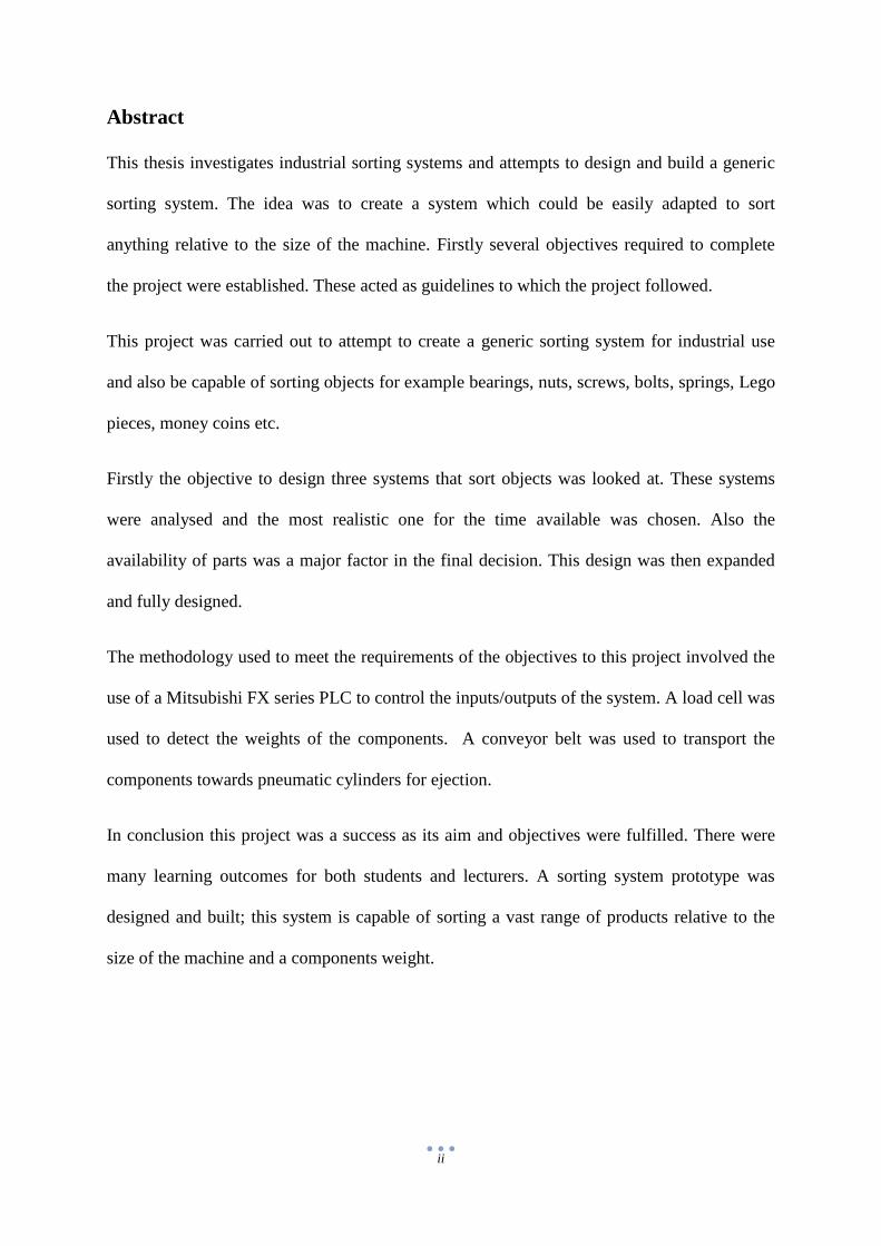
the memory which is called the RAM (D.J.Dunn, 2014). Shown in Figure 4 is a schematic
diagram of a PLC. The system must be able to communicate with external devices such as
programmers, display monitors and Analogue/Digital converters.
7
Figure 4: PLC Diagram (Selectautomation.blogspot.ie, 2014)
The basics of PLC’s operation can be broken down to input devices (e.g. mechanical
contacts, proximity sensors), output devices (e.g. motors, solenoids) from the machine or
process to be controlled are connected to the PLC (Crispin, 1990). The user enters a sequence
of instructions into the PLC’s program memory and the controller monitors the state of the
inputs and switches outputs according to the program.
Different manufacturers of PLC’s use their own unique coding language. However these
coding styles are similar to each other, for example a Mitsubishi FX series PLC’s use the
letter ‘M’ to initiate internal relays, where Allen-Bradley use the letter ‘B’ but follow the
same logic and programming style.
PLC’s are digital devices, they are only capable of reading digital values; this can be a
problem when the input is an analogue signal for example measuring speeds, weights, light,
sounds etc. To resolve this problem Analogue to Digital Converters, (ADC’s), are used.
An analogue to digital converter (ADC) produces a digital output from an analogue input.
When the start convert signal is pulsed the ADC converts the analogue input at that time into
an equivalent digital value, as shown in Figure 5. The ADC then produces an end of convert

8
signal to indicate that the conversion has finished (Crispin, 1990). This digital signal can then
be used by the PLC to control outputs.
Figure 5: Analogue to Digital Conversion (Allaboutcircuits.com, 2014)
2.3.3 Networking
Networking is a method which is used to communicate between two or more devices. The
information transfer may involve a point to point link such as a computer to PLC or a
network of various types of devices. All communication interfaces are either parallel or
serial.
A serial communications interface (SCI) lets devices exchange data one bit at a time. Usually
to a microprocessor, printers external drives and USB's. Serial interfaces have specific
advantages over parallel interfaces. The main advantage is simpler wiring. Serial interface
cables can be longer than parallel interface cables. This is because there is much less
crosstalk among the cables (Rouse, 2011).
Parallel interfacing is an interface between a computer and a device where the computer
sends multiple bits of information to the device simultaneously (princeton.edu, 2014).
Parallel ports can have up to 9 inputs bits and 12 output bits at any one time because it uses
multiple wires to transmit data.

9
Parallel Port’s have been standardized under the IEEE 1284 standard. This was first released
in 1994.
This standard defines 5 modes of operation which are as follows,
i. Compatibility Mode
ii. Nibble Mode
iii. Byte Mode
iv. EPP Mode (Enhanced Parallel Port)
v. ECP Mode (Extended Capabilities Port)
This was done to make new drivers and devices compatible with each other (Peacock, 1998).
Figure 6: Parallel and serial interface (newhavendisplay.com, 2002)

10
2.3.4 Pneumatics
In a very broad term, pneumatics is,
"the branch of physics or technology concerned with the mechanical properties of gases"
(Definitions, 2014).
Pneumatics is compressed gas usually air. The air is pressurised and is used to actuate the end
effecter and do mechanical work. The end effecter is usually a common cylinder but can
range from grippers to vacuum cups. Pneumatics is commonly used in the following
industries:
Medical
Packaging
Material Handing
Entertainment
Robotics
Pressures of 100-150 psi are commonly used in pneumatic systems. This is only a fraction of
the pressure hydraulic systems use. 3000-5000psi is common for hydraulic systems.
Pneumatics are used when small loads apply, the gas can be compressed so this leads to low
levels of accuracy. A pneumatic system typically comprises of many parts. A compressor
takes in air at atmospheric pressure and compresses it to 100-150psi. when air is compressed
it drops the moisture it holds so bleeder valves have to be incorporated into system. Hoses
take air to the valves. Valves can be pure pneumatic or electro pneumatic. The valves activate
or deactivate the cylinders.

11
2.3.4 Electric Motors
Electric motors have been an important element of the industrial and commercial economy
for over a century. Electric motors operate through the interaction of magnetic flux and
electric current. Electric motors are broadly classified into two categories: AC and DC.
Shown below in Figure 7 is the basic principal of how a motor operates when current is
passed through a coil, creating magnetic force.
Figure 7: Basic operation of a motor (Elpaso.apogee.net, 2014)
DC Motors
DC motors operate with terminal voltage and current that is substantially constant. These
motors are usually applied in two broad types of application. One of these categories is when
the power source itself is DC. That is why motors in vehicles are all DC, from the motors that
drive cooling fans to the starter motor. The other reason for using DC motors is that their
torque-speed characteristics are easier to tailor (Beaty, 1998).
DC motors have six basic parts: an axle, rotor, stator, commutator, field magnets, and
brushes. In most DC motors the external magnetic field is produced by high-strength
permanent magnets (Solarbotics.net, 2014). The stator is the stationary part of the motor; this
includes the motor casing, as well as at least two permanent magnet pole pieces. The rotor

12
rotates with respect to the stator. The rotor consists of windings, these windings being
electrically connected to the commutator. Shown below in Figure 8 are the different
components of a typical DC motor.
Figure 8: Components of a DC motor (Electrical4u.com, 2014)
AC Motors
These are motors designed to operate with alternating current (AC) supplies, they are classed
into two categories: induction and synchronous. AC motors work by setting up a magnetic
field pattern that rotates with respect to the stator and then employing electromagnetic forces
to entrain the rotor in the rotating magnetic field pattern (Beaty, 1998).
Synchronous motors have a magnetic field which therefore rotates at the same speed as the
stator magnetic field. Synchronous motors are not used as much as induction motors because
their rotors are more complex and they require exciters.
Induction motors are the most used motor today. Induction machines are simple, rugged and
usually are cheap to produce. They dominate in applications at power levels from fractional
horsepower to hundreds of horsepower (Beaty, 1998).

13
A 3 phase induction motor gets its name from the fact that the rotor current is induced by the
magnetic field, instead of electrical connections.
The operating principle of a 3 phase induction motor is based on the production of r.m.f.
The stator of an induction motor consists of a number of overlapping windings offset by an
electrical angle of 120°. When the primary winding or stator is connected to a three phase
alternating current supply, it generates a rotating magnetic field which rotates at a
synchronous speed (Application basics of operation of three-phase induction motors, 2014).
The direction of rotation of the motor depends on the phase sequence of supply lines, and the
order in which these lines are connected to the stator. Switching any of the two phases will
results in a change in direction of rotation.
The number of poles and the frequency of the applied voltage determine the synchronous
speed of rotation in the motor’s stator. Motors are commonly configured to have 2, 4, 6 or 8
poles. The synchronous speed is a term given to the speed at which the field produced by
primary currents will rotate, this determined by the following expression:
𝑠𝑦𝑛𝑐ℎ𝑟𝑜𝑛𝑢𝑠 𝑠𝑝𝑒𝑒𝑑 =(120 × 𝑠𝑢𝑝𝑝𝑙𝑦 𝑓𝑟𝑒𝑞𝑢𝑒𝑛𝑐𝑦)
𝑁𝑢𝑚𝑏𝑒𝑟 𝑜𝑓 𝑝𝑜𝑙𝑒𝑠 𝑜𝑛 𝑡ℎ𝑒 𝑠𝑡𝑎𝑡𝑜𝑟 (James, 2012)
Figure 9: Production of rotating magnetic field in an induction motor (James, 2012)

14
2.3.6 Three Phase Power
Three phase power is generated in a power plant. Three different AC wave forms of 220volts
are generated simultaneously. These 3 phases are offset by 120 degrees each. Four wires
come from the power plant, 3 AC phases and a neutral. Three phase power is derived by the
following equation:
√3 . 𝑉𝑖𝑛. 𝐼. 𝐶𝑜𝑠(𝜑)
Vin = voltage per phase (V, volts)
I = current (A, amps)
Cos Φ = power factor
For example when the voltage per phase is 220volts at 1amp and the power factor is 1, then:
√3(220)(1)(1)
𝑉𝑜𝑢𝑡 = 381 𝑣𝑜𝑙𝑡𝑠
For large machines and some welders three phase power is preferred over single phase. This
is due to many reasons such as:
Higher voltage
No need for rectification
Constant power delivery
No start capacitors or extra control wiring
Uniform torque
Motors are generally smaller
15
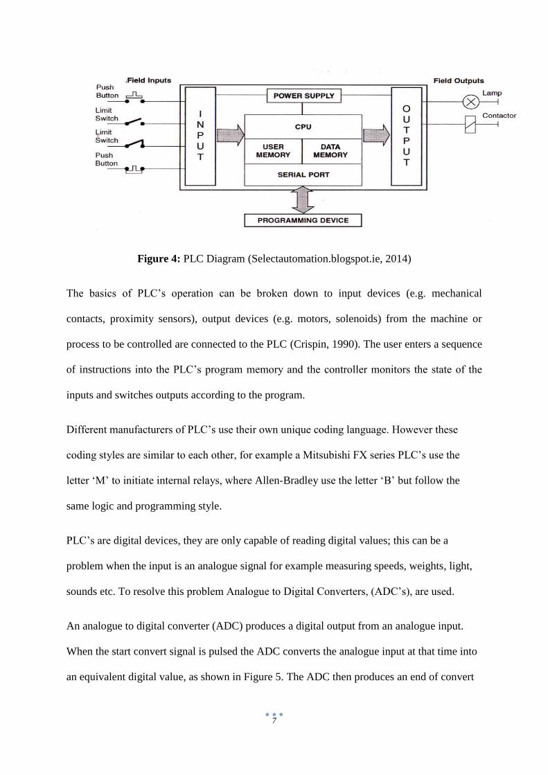
Three phase power is just three single phase waveform brought together at 120 degree
intervals. The following figure illustrates how three phase power works.
Figure 10: Three Phase Power (Smith, 2012)
The neutral wire is always at 0 volts relative to all three phases, while the voltage of the three
phases never drops below positive.
2.3.7 Star Delta Configuration
Star and delta connections are used on electrical motors. This is because three phase motors
are generally always started off the supply lines. When starting a three phase motor large
current is needed but large current surges cause’s disturbances in the supply lines. To
overcome this problem low voltage is used when starting a motor and then full supply is
connected when the motor is near rotational speed.

16
When starting a large motor, the motor windings are connected in star. This reduces the
voltage and torque by a factor of 3. When the motor gets up to speed the windings are
reconfigured into delta.
Figure 11: Star and Delta conections (JIGUPARMAR, 2012)
A star/delta starter is made from many components such as:
Three contactors
A timer
A thermal overload
Time relay
Fuse elements
The contactors only have to control winding currents so they are smaller than direct line
contactors. When starting the motor only one contactor is open, this is called the star
contactor. Star is one third the current of delta. A time relay is built into the starter. When the
motor is started the star contactor opens, after a period of time it closes and the delta
contactor opens. This is standard practice on all three phase motors over 5hp.

17
3. Methodology
3.1 Introduction
This section aims to discuss the different methods which were considered in meeting the
overall aim of the project. It presents information on the design and build of the chosen
method and any technical issues and problems met along the way.
3.2 Initial design concepts
The first objective of the project was to produce three separate design concepts in which the
aim; designing a generic sorting system, could be satisfied. These three concepts were all
based around using a conveyor system.
3.2.1 Design Concept 1
The system is controlled by a PLC.
Coins loaded to a load cell for component detection via vibrating bowl.
Bursts of air from air valves used to eject components into their corresponding chutes.
Figure 12: Concept number 1

18
3.2.2 Design Concept 2
This system is controlled by a PLC.
Coins are loaded to a load cell for component identification via a vibrating bowl.
Stepper motors guide components to their corresponding chutes for ejection.
Figure 13: Concept number 2

19
3.2.3 Design Concept 3
This design uses ® Vision Assist to do two things: detect components, and decides
where along the system a component is to be ejected.
Pneumatic cylinders are actuated to push components down their corresponding
chutes.
Figure 14: Concept number 3
3.3 Final Design Concept
This section shows how the final design was arrived at. The final design concept is a
combination of concept number 1 & 2 discussed above.
In reference to Figure 15 below the logic behind the system is as follows:
Components are placed onto a load cell for identification based on their weight.
The conveyor belt transports the component down the line.
Pneumatic cylinders eject components into the desired chutes.
This system is controlled using a PLC

20
Figure 15: Final Design
The options of using LabVIEW® and PLC’s were analysed and the result was to use a PLC
as there was no previous experience with LabVIEW®. A PLC was chosen to control the
system as PLC programming was looked at theoretically in lecturers and the students have
experience in PLC programming. Whereas LabVIEW® had never been covered and is a
project in itself to gain the ability of programming complex systems with it.
Analysis on component ejection methods were also carried out. The three ejection methods
up for discussion were bursts of air, the use of stepper motors and pneumatic cylinders.
The first ejection method to be eliminated was the use of bursts of air. It was felt that
components could be more accurately ejected by physically guiding them off of the conveyor
belt as opposed to blowing them off with compressed air.
With the option of using bursts of air eliminated, left to discuss was the use of either
pneumatic cylinders or stepper motors to guide components from the sorting machine to their
next station.

21
This discussion resulted in choosing the option of pneumatic cylinders for the ejection
method. The main factors that influenced this decision were the fact that pneumatic cylinders
were available on hand in a wide range of specifications as opposed to the range of stepper
motors available. Another important factor taken into consideration was how complex stepper
motors are to control in comparison to pneumatics.

22
3.4 The Build
3.4.1 Introduction
This section is dedicated to the building process of the project. This section aims to clearly
highlight and outline the step by step process in which the project was unfolded and
completed. Each step will be discussed in detail from the initial interaction with the previous
project to the satisfactory outcome of the initial aim of this project.
3.4.2 Rewiring of the power circuit
The previous students who had worked on the conveyor system were using it to fill water
bottles. The first step was to dismantle the parts previously installed as they were no longer
needed.
The wiring of the power circuit was deemed unsafe by supervisor Mr. David Williams as the
wiring previously carried out was not colour coded; all wires were blue, hence making it
difficult to distinguish between live, ground and neutral wires.
First the power circuit was fully stripped. The power supply is three phase so the first step
taken was to wire each phase through 220V Mini Circuit Breaker’s (MCB’s). Next one of
these phases was wired into the live terminal on the PLC. A contactor with a 220V coil was
then installed and the three phases were wired to it. This contactor is used to control the three
phase induction motor which drives the conveyor belt.
(See appendix A for the power circuit diagram).

23
3.4.3 Control circuit
After analysing the control options a decision was made to use a PLC to control the
inputs/outputs of the system. This control circuit consists of 3 inputs and 6 outputs, as shown
in Table 1 below:
Table 1: Control circuit I/O List
Inputs Outputs
X0 – Start Button Y0 – 3 phase induction motor (contactor)
X2 – Stop Button Y1 – Electro-pneumatic solenoid 1
Analogue to Digital module signal Y2 - Electro-pneumatic solenoid 2
Y3 - Electro-pneumatic solenoid 3
Y4 - Electro-pneumatic solenoid 4
Y5 - Electro-pneumatic solenoid 5
Unfortunately due to inexperience it was not realised that the initial used FXo-30MR series
PLC, as shown below in Figure 15, could not be networked with an analogue to digital
converter which was required to carry out this project.

24
Figure 16: FXo series PLC installed
This problem was rectified by installing an FX1N series PLC (See Figure 16) and rewiring
the control circuit as described below.

25
Figure 17: FX1N series PLC and ADC installed
The sync-source (s/s) terminal on the PLC was looped into the 0V terminal. This means that
it is sinking outputs (NPN). The outputs pull current through the load and the common
connection to the load is 24 VDC (+DC) line (Defining sinking and sourcing I/O, 2014). The
current flows from +24 VDC to 0 VDC.
The start button was installed and wired normally open into the PLC as input ‘X0’. The stop
button was wired normally closed into the PLC as input ‘X2’. Normally closed means it’s a
push to break button.
Five electro-pneumatic solenoid valves were wired into the PLC. This consisted of
connecting each of the 0V leads from the solenoids into the 0V terminal on the PLC. The
26
24V leads from the solenoids were wired respectively into their corresponding output
terminals on the PLC as stated above in Table 1.
The last component to be wired was the three phase contactor which controls the induction
motor. (See appendix A for control circuit).
3.4.4 Installation of Pneumatics
Before installing the pneumatic system all the parts had to be sourced first. These included:
Air pressure regulator
Five 5/2 valves
5 pneumatic cylinders
Festo pneumatic hoses
A bracket to hold the 4 pneumatic ejection cylinders had to be manufactured. (See appendix
C for CAD drawings). The 4 cylinders were placed on the bracket at 45 degree angles to the
conveyor as shown below in Figure 18. This ensured when a component approached an
extended cylinder it would be pushed off the conveyor.
The cylinders were bolted to the bracket with 4 bolts per cylinder. When a cylinder was
activated its ram would cross the full width of the conveyor ensuring ejection of a
component. Five 5/2 valves were also mounted onto the bracket, these can be seen in Figures
17 & 18.

27
Figure 18: Electro-pneumatic solenoids
These solenoids were connected to a manifold as shown above in Figure 17; the manifold is
piped to the cylinders. The solenoids are wired to the PLC. They were controlled by an
electric relay that was part of the 5/2 valve. The air pressure regulator was then connected to
the 5/2 valves. This gave control over the amount of pressure that was in the system and was
very helpful during testing. A heavy duty festo hose had to be sourced to connect the air
pressure regulator to a line supply. This hose was rated to withstand a higher pressure then
what the system was capable of delivering.

28
Figure 19: Pneumatic cylinders & solenoids installed
3.4.5 Chute Manufacturing
A way of collecting the coins after they were ejected had to be implemented. A cute was
designed that would bolt to the conveyor, not interfere with the belt and safely carry away the
components. See appendix D for final design. Four of these chutes were made for the 4
ejection cylinders. They were made from aluminium and could have a coin bag attached to
catch coins. (See appendix C for CAD drawings).
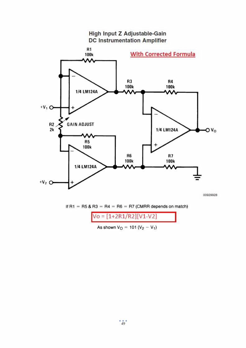
3.4.6 Load Cell signal conditioning
A load cell with a resolution of 0.1 gram increments was required. This ensured that light
components such as money coins could be sorted. A 50 gram load cell with .001 gram
resolution was sourced. This scale’s was stripped of the protective plastic exposing the

29
circuit. The 2 signal wires coming from the load were identified and then tapped into.
The voltage across these wires was approximately 600 micro volts. This voltage was far too
small for the analogue to digital converter to read so this signal had to be amplified. This was
done using an amplifying circuit.
The amplifying circuit consisted of:
Five 100k resistors
2k potentiometer
One 620k resistor
LM 324 Chip (4 op amps)
9 volt power source
Breadboard
This circuit gave a gain of about 8000. The gain was derived by the following equation.
𝑉𝑜𝑢𝑡 = (1 + 2𝑅1
𝑅2) (𝑉1 − 𝑉2)
Where R1 = 620k, and R2 = 2k.
(See appendix D for electrical diagram of the amplifying circuit).
The output from the amplifying circuit was about 4.7 volts. This output was connected to the
VIN port in the analogue digital converter while the negative from the 9 volt power source
was connected to the common.
3.4.7 Configuration of the Analogue to Digital Converter
The ADC used is a Mitsubishi FXoN-3A series ADC which can be seen in Figure 16 in
section 3.4.3. This ADC had one input; this input was from the load cell amplification circuit.
Analogue voltage between 0 and 4.7 volts is taken from the load cell. The ADC is an 8 bit

30
module so therefore it has 256 steps (28) minus one step for plus and minus sign. The voltage
is translated into 255 digital steps so the PLC can read it.
Channel 1 of the ADC was first calibrated for 0-5V. The digital value read in buffer memory
17 is placed into the PLC’s data register 0, so that this value can be put to use within the main
program. The ADC configuration can be seen within the PLC program in (Appendix F).
3.4.8 PLC Code
Once all mechanical parts were installed and all electrical & electronic circuits were wired
the only task left to do was write a PLC code which would control the sorting system. This
was one of the more difficult tasks and required a lot of troubleshooting before the finished
product was arrived at.
First in the program is the conditions required for the conveyor belt its self to run. Then the
ADC is configured. Once the ADC was configured it was possible to do comparisons with
the digital values being read from the ADC for different weights applied to the load cell.
Comparisons were written in the program to prove that the system works. The weights of a
€2 coin, a 10c coin and an M10 nut were calibrated within the program so that the machine
recognises and sorts these products into the desired stations. This proves that such a system is
capable of sorting more than just one component at a time.
Once a component is placed onto the load cell the digital value is sampled and placed into
data register 0 (D0). If the value within D0 falls within any of the pre-set constraints then the
components is ejected from the load cell, onto the conveyor and guided to the desired station.

31
The load cell and ejection cylinder (Y5) can be seen in Figure 19.
Figure 20: Load cell & ejection cylinder (Y5)
(See appendix E for PLC program).

32
4. Results and Analysis
4.1 Introduction
This section is used to present the overall results of the project and analyses the potential
abilities of the system.
4.2 Results
The majority of the projects objectives were complete; hence this produced some results as
expected. The machine is capable of sampling a components weight and converting it to a
digital value. A PLC program was generated to sort three separate components to prove that
the sorting system works. An electro-pneumatic circuit was successfully installed. The three
phase power supply was successfully rewired to a safe standard. The load cell’s analogue
signal was amplified to the required voltage of 4.7 volts. Signal conditioning was carried out
on the analogue signal wires and a great lesson learnt. A fully working prototype of a generic
sorting system was produced.
4.3 Analysis
The system has very good repeatability. When a component is placed on the load cell it is
found that the digital value was being read accurate to two digital values. The PLC program
required good repeatable readings from the load cell in order to set valid constraints within
the code. For certain operations to happen the values must not fluctuate by more than 2-3
digital steps.
The implemented pneumatic circuit worked 100% of the time and successfully carried out its
purpose of both ejecting components from the load cell to the conveyor and also guiding
components onto the chutes.

33
The three phase power supply was colour coded correctly and the power circuit was
implemented safely.
An amplification circuit was designed and constructed to produce a gain of approximately
8000, hence which amplified the analogue signal to approximately 4.7 volts.
It was found that electrical noise was affecting the analogue signal wires. To overcome this
problem the two signal wires were twisted tightly together and then shielded using tin foil.
34
5. Discussion
This section aims to give an overall evaluation of the project. The learning outcomes of the
project will be discussed along with the problems that were encountered. An overall opinion
of the project will also be expressed.
The overall aim of this project was to design and build a generic sorting system.
The objectives for the project were as follows:
To come up with three design concepts for systems that sort products safely.
To analyse these concepts and choose the most efficient and realistic one for the time
frame available.
To expand on the chosen system and have it designed by December.
To build the system to sort objects for example money coins.
To test the system sorts approximately 205 coins/min.
The first objective required exploring the different methods of satisfying the aim of the
project. This research was narrowed down to three design concepts, as shown in Figures 12,
13 and 14 in section 3.
Second in the objectives list was to analyse and evaluate each aspect of the three design
concepts to result in a final design with the most suitable configuration out of the three. The
final design was then expanded in greater detail as the project progressed and different issues
needed to be dealt with.
The I/O’s of the system were planned; these can be seen in Table 1 and in the control circuit
diagram found in Appendix B. The brackets required for mounting the pneumatic cylinders
were designed using Solidworks®, also the ejection chutes were designed using this CAD
software. Drawings for these parts can be found in the appendices section of this thesis.
35
Once the final system was fully designed and analysed the objective of building the system to
sort components for example money coins was undertaken. The process to which this
objective followed is described within the methodology section of this thesis. In conclusion to
this objective, it is evident that when the research that is reflected within the final design was
put to physical use the build of the machine was a success. The machine operates by using
electro-pneumatics, a conveyor belt and a load cell, which are controlled by using a
Mitsubishi FX1N series PLC.
The final objective of testing that the system sorts approximately 205 coins/min unfortunately
was not completed. This is due to the simple fact that time ran short and hence the throughput
of the machine was not tested. From observations an educated guess can be made that the
throughput of the sorting system is much lower than the desired 205 coin/min. Although a
number of factors could be taken into consideration in how the throughput could be raised
towards the initial expectations. Some of these factors include:
Tweaking down some of the timers within the PLC code.
Using a variable speed controller on the induction motor which drives the conveyor.
Reducing the sampling time in which the load cell reads components weights.
Using limit switches with the pneumatics to ensure the smooth operation of the
system.
In order to control the sorting machine a number of things required research to be put in place
before the control program could be wrote. First off, an amplification circuit had to be built.
This was necessary as the analogue signal produced by the load cell was far too minute for an
analogue to digital module and PLC to effectively use. The creation of this amplifying circuit
required a good understanding of how operational amplifiers (op amp’s) work. This proved to
be a challenging aspect during the project. An LM-324 chip, which contains four op amp’s,

36
was the main component in the amplifying circuit. This amplifying circuit proved to be a very
good learning outcome as the circuit was built and tested several times and a good
understanding of how to adjust the gain of such circuits was gained throughout building this
circuit.
It was realised that and analogue to digital converter (ADC) was required. The amplifying
circuit has two analogue signal wires which are referred to as V1 and V2. The circuit
amplifies the difference in voltage between these two leads by the gain of the circuit. There is
just one output wire from the amplifying circuit. This wire is the amplified analogue signal
from the load cell. A PLC cannot read analogue signals. This is the reason why an ADC was
used. The use of the Mitsubishi FXoN-3A ADC brought some learning outcomes with it. The
calibration of an ADC was learned, which required the use of an external power supply to
calibrate the module’s channel 1 (H00) between 0-5 Votls. Also so knowledge was gained on
adjusting the ADC’s offset and gain. This process was carried out but turning the built in
potentiometers on the module until the desired digital values were acquired. This part of the
project was very interesting and a lot was learned about ADC’s.
Once the analogue signal had been converted into a digital signal the PLC could now
recognise the load cell signal changes. The actual writing of the PLC code turned out to be a
challenge. Programming had been studied in a semester 1 module of the coarse called
mechatronics 1, but when it came to putting this knowledge to practical use it brought some
difficulty. The program required the configuration of the ADC so that the PLC could read the
digital values from the ADC’s buffer memories into a PLC data register. Once the
configuration was done, the values being read in D0 could be programmed to get the machine
to carry out the tasks required to sort components. This was a great learning outcome and
good experience putting the theory previously learned to practical use.

37
Throughout the project many issues arose which required rectification. Some of these issues
have been mentioned throughout the thesis. The greatest problem encountered in carrying out
this project and by far the greatest lesson taken was electrical noise interference. Electrical
noise caused problems in reading stable digital values within the PLC. After many hours of
troubleshooting this problem, it was found that the analogue signal wires coming from the
load cell and the amplifying circuit were picking up electrical interference. This problem was
overcome by using some simple signal conditioning strategies. The signal wires were twisted
tightly together, this aimed to share the error being conducted evenly across the wires and
hence minimising fluctuation in digital values. Also these signal wires were shielded using
aluminium foil. This was done to minimise the amount of electrical noise being conducted.
After carrying out some signal conditioning on the signal wires, a huge improvement could
be noticed in the amount of fluctuating that the digital values were doing. Not all fluctuation
had been stopped so this lead to some more troubleshooting as to why. As a result of this
troubleshooting it was found that static electricity had been affecting the breadboard on
which the amplifying circuit was built. This problem was rectified by placing some anti-static
foam between the control box and the breadboard. It was then found that almost all
fluctuation in the digital values had been removed, this meant the signal could be used for
programming.
The use of timers within the PLC code required a lot of trial and error testing. The use of
limit switches could have made the programming process a lot less complex, but this issue
only came to attention when the code was to be written. There was not enough time to order
limit switches and then install them so the more complex programming method had to be
carried out using internal timers.

38
6. Conclusions and Recommendations
6.2 Introduction
This Section summarises the project and the major steps taken to achieve the aim and
objectives. Major findings will be discussed and summarised and finally recommendations
will be made based on observations that were made throughout the project.
6.3 Conclusion
The aim of this project was to build a generic sorting system. This has been achieved and the
design and build can be viewed in section 3 of this study. Five objectives were set out at the
start of the year and in conclusion four out of the five objectives have been complete.
Evidence from section 2 indicates that mechanical sorting systems are replacing manual
human sorting operations. It is expected that the amount of mechanical sorting systems in
industry will rise in the coming years. This is due to faster processing abilities and cheaper
costs to run, implement and service these machines.
There were various steps involved in the project. The initial steps taken in the project were to
design systems that satisfied the aim. These designs were analysed and a final design was
chosen. Much thought went into this step because the entire project would be made to this
design. If this design didn't work or there was a flaw with a certain aspect of the design the
system would not work. It was critical that the final design had no errors or short comings.
The next step in the project was to acquire all of the components. This step involved many
hours searching for pneumatic cylinders, valves, switches, hoses and most importantly a
suitable load cell.
Once these components were acquired they had to be assembled. This process consumed the
most time that was allocated for the project because of the sheer amount of manual work
involved.

39
Finally when the mechanical, electrical and electronic components were in place, the program
for which would operate the system was wrote. This step had many problems in it, but these
were rectified after a lot of troubleshooting.
6.4 Recommendations
Overall the project was a success. However if this project was attempted again there would be
a few recommendations on different aspects of the project such as:
If components needed to be inspected for wear or damage a vision system should be
implemented. The current system does not inspect for damage, wear or contamination
of the components.
The implementation of LabVIEW® offers a wider range of freedom in programming
capabilities and can also accommodate a vision system.
A safety unit should be made to protect users from the pneumatic cylinders, conveyor
and electrical equipment when the machine is operating.
An automatic feeding system should be implemented to place components onto the
load cell one at a time. This would remove human operators and the system could run
entirely by itself.
6.5 Summary
In conclusion the project was a success, as the aim and majority of objectives set out were
satisfied. A system capable of sorting a vast range of products and components was designed
and built. From a critical point of view there is room for improvement to be made by students
who may take on this project in the future. Each of the above recommendations would be
very beneficial to the project and if implemented would give more accurate results. The
recommendations above can be carried out using the equipment provided by WIT.

40
References
Beaty, H. W., 1998. ELECTRIC MOTOR Handbook. New York: McGraw-Hill.
Beck, R., n.d. http://people.howstuffworks.com/usps5.htm. [Online]
[Accessed 19 March 2014].
Bridged, U., 2014. Dictionary.com. 19 march.
Crispin, A. J., 1990. Programmable Logic Controllers and their Engineering Applications.
Glasgow: McGraw-Hill Book Company (UK) Limited.
D.J.Dunn, 2014. Programmable Logic Controllers. [Online]
Available at: http://www.freestudy.co.uk/plc/outcome1.pdf
[Accessed 20 March 2014].
Definitions, G., 2014. www.google.com. [Online]
Available at:
https://www.google.ie/search?q=what+is+pneumatics&rlz=1C1CHWA_enIE575IE575&oq=
what+is+&aqs=chrome.0.69i59l3j69i57j69i59j0.2357j0j8&sourceid=chrome&espv=210&es
_sm=93&ie=UTF-8
[Accessed 1 4 2014].
Goodwine, B., 2002. www.newhavendisplay.com. [Online]
Available at: https://www.newhavendisplay.com/app_notes/parallel-serial.pdf
[Accessed 1 4 2014].
Peacock, C., 1998. beyondlogic.org. [Online]
Available at: http://retired.beyondlogic.org/spp/parallel.pdf
[Accessed 1 4 2014].
princeton.edu, 2014. wordnetweb.princeton.edu. [Online]
Available at: http://wordnetweb.princeton.edu/perl/webwn?s=parallel interface
[Accessed 1 4 2014].
Ribao Technology, Inc, 2012. http://www.ribaousa.com/. [Online]
Available at: http://www.ribaousa.com/showProDetail.asp?ID=16&ClassID=24
[Accessed 19 March 2014].
Rouse, M., 2011. http://whatis.techtarget.com/. [Online]
Available at: http://whatis.techtarget.com/definition/serial-communications-interface-SCI
[Accessed 1 4 2014].
wiseGeek, 2014. What Is a Programmable Logic Controller. [Online]
Available at: http://www.wisegeek.org/what-is-a-programmable-logic-controller.htm
[Accessed 20 March 2014].

41
Selectautomation.blogspot.ie. 2014. SELECT AUTOMATION - Tuning your needs: PLC-
basic Block Diagram. [online] Available at: http://selectautomation.blogspot.ie/2009/11/plc-
basic-block-diagram_26.html [Accessed: 7 Apr 2014].
Allaboutcircuits.com. 2014. Introduction : Digital-analog Conversion. [online] Available at:
http://www.allaboutcircuits.com/vol_4/chpt_13/1.html [Accessed: 7 Apr 2014].
Elpaso.apogee.net. 2014. Motors & Drives. [online] Available at:
http://elpaso.apogee.net/md/mfphowm.asp [Accessed: 7 Apr 2014].
Allaboutcircuits.com. 2014. Introduction : Digital-analog Conversion. [online] Available at:
http://www.allaboutcircuits.com/vol_4/chpt_13/1.html [Accessed: 7 Apr 2014].
Solarbotics.net. 2014. DC Motors -- principles of operation. [online] Available at:
http://www.solarbotics.net/starting/200111_dcmotor/200111_dcmotor2.html [Accessed: 7
Apr 2014].
Smith, 2012. www.homebrewtalk.com. [Online]
Available at: http://www.homebrewtalk.com/f170/3-phase-power-questions-
348783/index6.html
[Accessed 2014 4 7].
JIGUPARMAR, 2012. electrical-engineering-portal.com. [Online]
Available at: http://electrical-engineering-portal.com/star-delta-motor-starter
[Accessed 7 4 2014].
Electrical4u.com. 2014. Working or Operating Principle of DC Motor | Electrical
Engineering. [online] Available at: http://www.electrical4u.com/working-or-operating-
principle-of-dc-motor/ [Accessed: 7 Apr 2014].
Application basics of operation of three-phase induction motors. 2014. [e-book] Aarau:
Sprecher+Schuh AG Rockwell Automation.
http://ecee.colorado.edu/~ecen5737/Files/induction%20machines%20paper%203.pdf
[Accessed: 7 Apr 2014].
James, H. 2012. Three phase induction motors - Operating principle | EEP. [online] Available
at: http://electrical-engineering-portal.com/three-phase-induction-motors-operating-principle
[Accessed: 7 Apr 2014].
Defining sinking and sourcing I/O. 2014. [e-book]
http://www.fluidairecompany.com/docs/pdfs/Q8answer.pdf [Accessed: 8 Apr 2014].

42
Appendices

43
Appendix A
Electrical Diagrams

44

45
Appendix B
CAD Drawings

46

47

48
Appendix C
Amplifying Circuit
49

50
Appendix D
PLC Program

51

52

53

54