Embed Size (px)
Citation preview

N d’ordre: 00000 ANNEE 2010
THESE
présentée devant L’ECOLE CENTRALE DE LYON
pour obtenir
Le titre de DOCTEUR SPECIALITE ACOUSTIQUE
par
Ying HU
DEVELOPPEMENT DE PANNEAUX HYBRIDES
PASSIFS/ACTIFS POUR L’ACOUSTIQUE
à soutenir le 17 Décembre 2010 devant la commission d’examen
Mme. Marie-Annick GALLAND (Directeur de thèse) M. Kean CHEN (Codirecteur) M. Philippe HERZOG (Rapporteur) M. Jincai SUN (Rapporteur) M. Shuyu LIN (invité) M. Boxiao CHEN (invité) M. Hong HOU
Laboratoire de Mécanique des Fluides et d’Acoustique, UMR CNRS 5509 Ecole Centrale de Lyon

Abstract
i
Abstract
Active acoustic structure is an effective structure for reducing the unwanted noise, and it
has been widely studied for engineering application. In this thesis, a hybrid active acoustic
structure having good acoustical absorption and insulation is developed, combining the
porous materials and active control technique. The secondary source is realized by an active
plate consisting of two piezoelectric patches bonded to an elastic thin plate in order to
improve acoustic insulation at low and resonances frequencies. The numerical results and
measurement data show that this structure has good absorption coefficient and transmission
loss after active control. The following works have been completed:
(1) The acoustic characteristic of the double-wall passive acoustic structure is analyzed
by the transfer matrix method. The definition of four acoustic matrices: the transfer matrix,
the scattering matrix, the impedance matrix, and the admittance matrix are given in the
acoustic structure, and the relationship between them is also expressed. Based on the sound
propagation principle, the transfer matrix of the elastic plate, the air gap, the porous material
and the interface between each layer are expressed and then the total transfer matrix of the
double-wall structure is deduced. Lastly, the absorption coefficient and transmission loss of
the double-wall acoustic structure are calculated and analyzed with some numerical examples.
(2) A hybrid active acoustic structure allowing good acoustic insulation and absorption
for a wide frequency range has been developed based on the scattering matrix method. The
scattering matrix of the active plate with the piezoelectric ceramics is expressed, and the
acoustic performance of the hybrid active structures has been calculated with and without
active control. According to the analysis results, the hybrid active acoustic structure is
designed for obtaining good acoustic insulation and absorption performance. The influence
factors which affect the acoustic properties of the developed hybrid active acoustic structure
have also been investigated.
(3) The acoustic performance of the hybrid active structure having poroelastic material is
analyzed by the finite element method. The finite model of the poroelastic material is
established based on the ( , )u p formulation, considering the elasticity of the skeleton and the
Abstract
ii
strong coupling between the solid and fluid phases. The boundary conditions on the coupling
surface of the elastic, poroelastic and air layers were formulated in Comsol modes. The
surface impedance of the poroelastic material was validated by Biot’s theory for different
boundary conditions. The absorption coefficient and transmission loss of some hybrid active
acoustic structures have been studied under plane wave excitation in Comsol environment and
the results are validated by the scattering matrix method for s limited frequency range.
(4) Experiments for determining the acoustic properties of the hybrid active structure are
carried out by the two source-location method. The reflection and transmission coefficients of
each layer in the hybrid active structure are tested, and the acoustic performance of some
hybrid active acoustic structure is measured, using FxLMS algorithm for finding the optimal
secondary source command in active control. The results in measurement are in good
agreement with that in the finite element method, and the transmission loss of these hybrid
structures can be improved obviously with active control for resonance frequency.
(5) A multi-cell hybrid active acoustic structure concept is proposed by juxtaposing
several single hybrid cells for reducing the noise in a large-area domain. The primary and
secondary pathway matrices have been obtained based on the multi-cell hybrid structure
consisting of an m n× ( , 1, 2,3,m n = ⋯ ) array of single hybrid cells. Some two-cell hybrid
structures are developed, for example, and their acoustic properties have been studied with a
rigid or elastic interface between each hybrid cell.
Key words: hybrid acoustic structure, porous material, transfer matrix, scattering matrix,
active control

Résumé
iii
Résumé
Les panneaux passifs, en particulier les doubles-cloisons, permettent d’obtenir de bonnes
performances en isolation acoustique pour éliminer les bruits indésirables en moyennes et
hautes fréquences. Ils ont été largement utilisés dans les domaines du bâtiment ou encore de
l’industrie du transport. Un panneau hybride actif/passif est ici étudié, afin d’obtenir de
bonnes performances en absorption et en isolation sur une gamme incluant des basses
fréquences. La source secondaire est réalisée par une plaque active composée de deux
céramiques piézo-électriques collées sur une plaque en acier. Le cœur du double panneau peut
inclure un matériau poreux pour améliorer les performances de l’ensemble. Les résultats
numériques et les données de mesure montrent que ces panneaux présentent sur une large
bandes de fréquences de bonnes performances avec contrôle actif. Les études suivantes ont
été réalisées:
(1) Les caractéristiques acoustiques du panneau passif sont analysées par la méthode des
matrices de transfert, qui est basée sur les expressions des ondes planes propagées dans
chaque élément de la structure : la plaque élastique, l'air et le matériau poreux, considéré
comme un fluide équivalent. Les conditions aux interfaces entre chaque couche sont
exprimées, puis la matrice totale de transfert du panneau est déduite. Enfin, la perte par
transmission et le coefficient d'absorption sont calculés et analysés. Des exemples
d’applications sont donnés à titre indicatif.
(2) La méthode des matrices de diffusion a été ensuite introduite afin de modéliser la
partie active du panneau hybride. La matrice de diffusion est ainsi exprimée pour une plaque
active comportant des céramiques piézo-électriques, et les performances acoustiques des
panneaux hybrides ont été calculées avec et sans contrôle actif. Une étude paramétrique a
permis de faire un bilan sur les possibilités effets par des panneaux hybrides en absorption
et/ou en isolation.
(3) Une méthode d’éléments finis est ensuite développée afin de prendre en compte le
comportement élastique du matériau poreux. En effet dans les applications vibro-acoustiques
Résumé
iv
comme celles étudiées ici, il n’est pas possible de considérer que le matériau se comporte
comme un fluide équivalent sur toute la gamme de fréquences. Le modèle éléments finis du
matériau poroélastique développé sous Comsol, est établi sur la base de la formulation en
déplacement- pression, compte-tenu de l'élasticité du squelette et du couplage fort entre les
phases solide et fluide de matériau poreau. Les conditions aux limites sur l’interface entre ce
matériau et les plaques ou l’air, ont été formulées et introduites dans la discrétisation du
problème. L'impédance de surface d’un matériau poroélastique a été ainsi calculée et la
méthode a été validée. La perte par transmission et le coefficient d'absorption des panneaux
hybrides actif/passif ont été déterminés pour différentes configurations et comparées aux
résultats obtenus par la matrice de diffusion. Les résultats sont en très bon accord sur une
large gamme de fréquences. Les différences s’expliquent par la prise en compte du caractère
élastique du matériau poreux et par les modes de flexion d’ordres supérieurs rencontrés dans
la méthode numérique.
(4) Une mise en œuvre expérimentale des panneaux hybrides a été réalisée au LMFA, en
conduit pour des ondes planes en incidence normale. La méthode des deux sources a été
utilisée pour déterminer les coefficients de réflexion et de transmission des structures
monocouche ou multicouches. Le contrôle actif a été réalisé au moyen de l'algorithme
FXLMS. Les résultats expérimentaux concordent avec les résultats obtenus par la méthode
des éléments finis. Notamment, la perte par transmission de ces panneaux hybrides peut être
améliorée par contrôle actif au voisinage de la fréquence de résonance.
(5) Un panneau hybride multi-cellules est constitué par la juxtaposition de plusieurs
cellules individuelles : l’objectif est de réaliser un traitement acoustique de surface étendue.
Le fonctionnement en contrôle actif est formalisé par l’introduction des transferts primaires et
secondaires. Un modèle éléments finis est proposé à titre d’exemple, avec deux cellules
séparées par une plaque rigide ou élastique. Les résultats montrent une dégradation des
performances lorsque le couplage inter-cellule est fort.
Mots clés: panneau hybride, matériau poreux, matrice de transfert, matrice de diffusion,
contrôle actif
Acknowledgement
v
Acknowledgement
There are many people without whom this work would not have been possible. I would
first like to thank my supervisor, Marie-Annick Galland, for taking me on as her student and
allowing me to pursue my research interests, and for her support and friendship during the
course of this thesis. She is, without question, a great master with genuine knowledge on
acoustics. Besides, she gave me a lot of helps not only in the daily life but also in the work
when I lived in France.
I would also like to thank my co-supervisor Kean Chen, who has quite good ideas for
helping me improve my work. Besides I wish to thank him for teaching me a lot on the
attitude of research. When I felt lonely in France or I was worried about my works, he
encouraged me greatly, and gave me many valuable suggestions to promote the advance of
the work, and he also patiently and critically proofread the manuscript.
I would like to give special thanks to my colleagues in France: Azzedine Sitel, Benjamin
Betgen and Cederic Batifol, who helped me very much in both the work and the language. I'm
really quite grateful for their kindness.
Also I would like to thank Prof. Jincai Sun, Prof. Meiping Sheng, Prof. Hong Hou and
Prof. Xiangyang Zeng. They helped me on both the work and the life when I was in
Northwestern Polytechnical University of China, and they are also concerned with my thesis.
I am also grateful to Prof. Sun and Prof. Hou for accepting to be members of the jury.
I would like to thank my colleagues in China: Dr. Han HU and Ms. Bing Li. They helped
me fill out the documents for preparing the oral defense when I was in France and could not
go back to China.
Thanks also to the friends from Lyon, with a special mentioning of Hang Yu, Dabing Luo
and Chuantao Yin. They are the closest friends of mine, and they made the life in Lyon more
than pleasant.
The most special thanks are to my husband, Wenxin Qu, for his support in these years.
And of course to my parents, I dedicate this thesis to them.

Contents
vii
Contents
Abstract..................................................................................................................................... i
Résumé....................................................................................................................................iii
Acknowledgement ................................................................................................................... v
Introduction............................................................................................................................. 1
1.1 BACKGROUND ................................................................................................................. 3
1.1.1 Active noise control................................................................................................. 3
1.1.2 The proposition and characteristic of active acoustic structure............................... 5
1.1.3 The development of active acoustic structure ......................................................... 5
1.1.4 The development of hybrid active acoustic structure .............................................. 7
1.2 RESEARCH METHOD....................................................................................................... 13
1.2.1 Mathematical methods for modeling hybrid active acoustic structure .................. 13
1.2.2 Measurement method of hybrid active acoustic structure ..................................... 15
1.3 OBJECTIVES OF THE THESIS ........................................................................................... 16
1.4 STRUCTURE OF THE THESIS ........................................................................................... 17
Acoustic performance analysis of double-wall passive acoustic structure by transfer matrix
method.................................................................................................................................... 19
2.1 THE ACOUSTIC PARAMETERS OF DOUBLE-WALL PASSIVE STRUCTURES ....................... 20
2.1.1 The sound pressure and the normal particle velocity ............................................ 21
2.1.2 The acoustic matrices ............................................................................................ 22
2.1.3 The transformation of the matrices........................................................................ 23
2.1.4 The acoustic properties of the double-wall structure............................................. 24
2.2 THE DERIVATIONS OF THE TRANSFER MATRIX .............................................................. 27
2.2.1 The transfer matrix of air layer.............................................................................. 27
2.2.2 The transfer matrix of porous material .................................................................. 28
2.2.3 The transfer matrix of an elastic plate ................................................................... 31
2.2.4 The transfer matrix between different medias ....................................................... 32
2.2.5 The total transfer matrix ........................................................................................ 34
2.3 NUMERICAL EXAMPLES ................................................................................................. 36
Contents
viii
2.3.1 Sound absorbent system ........................................................................................ 36
2.3.2 Sound insulation system ........................................................................................ 38
2.3.3 Sound absorbent and insulation system................................................................. 39
2.4 CONCLUSIONS ............................................................................................................... 41
Acoustic performance analysis of hybrid active acoustic structure by scattering matrix
method.................................................................................................................................... 43
3.1 THEORETICAL BASIS AND ANALYTICAL SIMULATION ................................................... 44
3.1.1 The acoustical behavior of an active plate............................................................. 44
3.1.2 The active sound absorbent structure .................................................................... 45
3.1.3 The active sound insulation structure .................................................................... 48
3.1.4 The active sound absorbent and insulation structure ............................................. 49
3.2 NUMERICAL EXAMPLES ................................................................................................. 52
3.2.1 Sound absorbent system ........................................................................................ 52
3.2.2 Sound insulation system ........................................................................................ 54
3.2.3 Hybrid systems ...................................................................................................... 56
3.3 INFLUENCE FACTOR OF ACOUSTIC PERFORMANCE IN HYBRID SYSTEMS....................... 58
3.3.1 The porous material layers .................................................................................... 58
3.3.2 The air gap layers .................................................................................................. 61
3.4 CONCLUSIONS ............................................................................................................... 63
Finite element study of hybrid active acoustic structure with poroelastic materials based on
the (u, p) formulation............................................................................................................ 65
4.1 THE BIOT’S THEORY OF SOUND PROPAGATION IN POROELASTIC MATERIAL ................ 66
4.1.1 The (u, p) formulation for poroelastic medium ..................................................... 66
4.1.2 Coupling boundary conditions............................................................................... 69
4.2 FINITE ELEMENT METHOD FOR MODELING HYBRID ACTIVE STRUCTURE ...................... 71
4.2.1 Passive process ...................................................................................................... 71
4.2.2 Active control ........................................................................................................ 73
4.3 NUMERICAL RESULTS AND VALIDATIONS ..................................................................... 74
4.3.1 The radiating plate ................................................................................................. 74
4.3.2 The active plate...................................................................................................... 76
4.3.3 Porous material ...................................................................................................... 79
4.3.4 Hybrid active acoustic structure ............................................................................ 82
4.4 CONCLUSIONS ............................................................................................................... 92
Experiments of hybrid active acoustic structure based on two source-location method 95
5.1 THE TWO SOURCE-LOCATION METHOD BASED ON THE SCATTERING MATRIX .............. 96
5.2 EXPERIMENTAL DISPOSITION ........................................................................................ 98
5.3 EXPERIMENTAL RESULTS ............................................................................................ 100
5.3.1 Sound leakage analysis........................................................................................ 100
5.3.2 The radiating and active plates ............................................................................ 101
5.3.3 The porous material ............................................................................................. 102

Contents
ix
5.3.4 Hybrid active acoustic structure .......................................................................... 103
5.4 ERROR ANALYSIS OF THE MEASUREMENT................................................................... 108
5.5 CONCLUSIONS ............................................................................................................. 110
Multi-cell hybrid active acoustic structure concept for noise control over a large surface113
6.1 THE MULTI-CELL HYBRID ACTIVE ACOUSTIC STRUCTURE CONCEPT........................... 114
6.2 ANALYSIS OF ACTIVE CONTROL .................................................................................. 115
6.2.1 The primary pathway matrix ............................................................................... 115
6.2.2 The secondary pathway matrix............................................................................ 116
6.2.3 The optimal vector for the secondary sources ..................................................... 116
6.3 NUMERICAL RESULTS .................................................................................................. 116
6.3.1 The two-cell structure with air gap...................................................................... 117
6.3.2 The two-cell structure with porous material ........................................................ 120
6.3.3 The two-cell structure with several layers ........................................................... 122
6.4 CONCLUSIONS ............................................................................................................. 126
Conclusions.......................................................................................................................... 127
7.1 THE FINISHED WORKS.................................................................................................. 127
7.2 PERSPECTIVES ............................................................................................................. 129
Notations .............................................................................................................................. 131
List of tables......................................................................................................................... 133
List of figures....................................................................................................................... 135
Appendix.............................................................................................................................. 141
Bibliography ........................................................................................................................ 149
Publications ......................................................................................................................... 163

Chapter 1. Introduction
1
Chapter 1
Introduction
Noise and vibration control is a very important issue in the military and civilian
applications. In social life and industrial production, the noise and vibration problem has
become more and more acute. With the social and economic development, people's concern
on the environment is becoming more important and noise pollution as a critical
environmental issue is attracting widespread attention. General speaking, excessive noise and
vibration will disturb people's normal life and work, whereas long-term exposure to high
noise environment can have serious damages on human hearing and physical health.
Meanwhile, the strong noise will result in sound fatigue of some industrial machinery and
equipment, which could shorten their working lives and even lead to accidents. In the military
field, noise will affect the operational performance of certain technical weapons. Especially
for the naval ships and underwater weapons, self-radiation noise will not only expose them,
but also reduce the working accuracy.
The reduction of noise and vibration is a major requirement for performance, sound
quality and customer satisfaction. From the view point of control strategy, it can be carried on
three sides: sound source, transmission path and receiver [1]. Noise control methods can be
divided into two categories: passive control and active control. The passive control
technology includes sound absorption, sound insulation, use of silencers, vibration isolation,
damping, and so on. The mechanism of passive control is dissipating the sound energy by the
interaction between the sound waves and acoustic materials or structures. However, the
passive control strategy is efficient enough at medium and high frequencies but exhibit the
drawbacks at low frequencies. For example, the porous material is widely used to eliminate
noise in engineering applications because of its good sound absorption performance in high

Chapter 1. Introduction
2
frequency. However, it has very poor absorption effect in low-frequency. In addition, for a
single material, the sound absorption ability and sound insulation effect are not balanced.
Such as a steel plate, it can be used as a good insulation material, but it has very poor sound
absorption effect; whereas, the glass wool can nearly absorb 99% of sound, but its
transmission loss has only 20dB. Therefore, we need to combine the passive method and
active control technique for remedying this problem.
Active control technique can be divided into two categories [1]: active noise control and
active force control. Active noise control [2] refers to utilize the sound source (such as
speakers) as the secondary source to produce the secondary sound field offsetting the
unwanted noise, it is in some documents also known as the "Attenuator"; active force control
[3] is exciting the acoustic structure (named the primary structure) to radiate the secondary
sound field. In recent years, in order to promote the active noise control technology in
engineering, a new active noise control is proposed, called active acoustic structure [4], which
establishes the secondary sound field by the distributed acoustic actuator, and offsets the
primary sound field via adjusting the strength of the secondary source. Active acoustic
structure concentrates the advantages of the active noise control and active force control
method, which represents a new development stage of active control technology.
Many active acoustic structures are already available and will be introduced as a
background in the next section, including active absorber structure and active insulation
structure. In Sec. 1.1.1 we review the development of the active noise control, and indicate
that the disadvantage of active noise control is the numbers and positions of the secondary
source and error sensor strongly depend on the external environment. In Sec. 1.1.2 the
proposition and characteristic of active acoustic structure have been described. In addition, it
has several advantages: less number of secondary sources, less dependent on the external and
expanding the band of the control frequency. Besides, the development of the active acoustic
structure is reviewed in Sec. 1.1.3. In Sec. 1.1.4 we review several hybrid active acoustic
structures for enhancing sound absorption and/or insulation, which combine both methods of
the passive control and active control.
The mathematical methods for calculating the acoustic performance of the hybrid active
acoustic structure will be introduced in Sec. 1.2. The transfer matrix method and the
scattering matrix method are efficient tools for modeling or optimizing these hybrid systems
because of simplicity. Indeed, they are very easy to be incorporated in the computation
program for the hybrid systems which cannot be modeled by analytical methods (ex: complex
boundary conditions, geometries…). However, when the porous material in the hybrid
systems is elastic or coupled with an elastic plate, the elasticity of the skeleton should be
considered, and the strong coupling between the solid and fluid phases cannot be ignored due
Chapter 1. Introduction
3
to the biphasic nature of the porous material. In this case, we review the finite element method
based on (u, p) formulation which is efficient for modeling the poroelastic medium. We
describe the objective and structure of this thesis respectively in Sec. 1.3 and 1.4.
1.1 Background
1.1.1 Active noise control
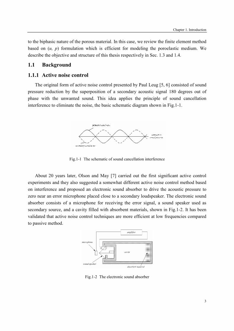
The original form of active noise control presented by Paul Leug [5, 6] consisted of sound
pressure reduction by the superposition of a secondary acoustic signal 180 degrees out of
phase with the unwanted sound. This idea applies the principle of sound cancellation
interference to eliminate the noise, the basic schematic diagram shown in Fig.1-1.
Fig.1-1 The schematic of sound cancellation interference
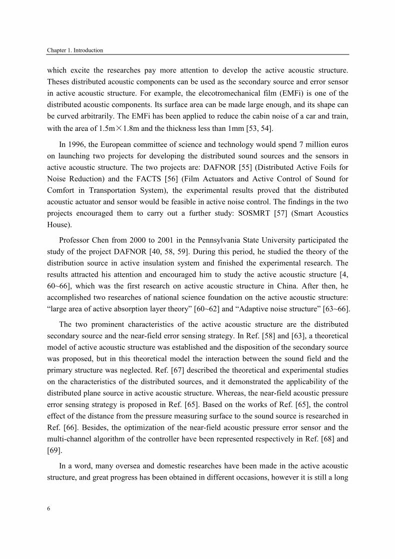
About 20 years later, Olson and May [7] carried out the first significant active control
experiments and they also suggested a somewhat different active noise control method based
on interference and proposed an electronic sound absorber to drive the acoustic pressure to
zero near an error microphone placed close to a secondary loudspeaker. The electronic sound
absorber consists of a microphone for receiving the error signal, a sound speaker used as
secondary source, and a cavity filled with absorbent materials, shown in Fig.1-2. It has been
validated that active noise control techniques are more efficient at low frequencies compared
to passive method.
Fig.1-2 The electronic sound absorber

Chapter 1. Introduction
4
For several decades, active noise control has achieved great progress with the efforts of
scientists in the world, and has established its own theoretical system and research
methodology [8, 9], its application in engineering is also gradually becoming more mature
[1,10]. In certain areas, active noise control has been applied into practical engineering, such
as active control of duct noise [11, 12], active noise earmuffs, and active muffler [13~16] and
so on. In three-dimensional space, the people have shown tremendous enthusiasm in active
noise control. For example, 22 research institutes of European countries had finished a
research on active noise control of the aircraft cabins [17]. The experimental results [18~23]
proved that active noise control is feasible in large-scale complex three-dimensional sound
field, however, it uses a large number of error sensors and speakers as secondary sources,
which made the whole control system bulky, heavy, and very complex, thereby the stability
was very poor. Besides, Deffaye and Nelson et al. [24] also proved that it is very limited to
use point source offsetting the radiating noise of the structure.
Fuller and his colleagues developed the technique of active force control [25~36] for the
noise vibration of the structure. They directly applied a secondary source into the vibrational
structure (called primary structure), and changed the structural response to offset the radiating
power. Over the past decade, although many great progresses have been obtained in active
control technique, this technology has a few applications in practice. The reason is that the
controlled structures in engineering application are very complex, and their vibration
responses are very complicated, so that it is difficult to achieve satisfactory effect with active
control [33~37]. In addition, if active force control is applied to light structures, the role of the
secondary source is easy to induce the structural fatigue and to result in potential accidents,
which is forbidden strictly in aviation, aerospace and other fields [36]; whereas for the
massive and rigid structures (such as ships, aircraft shell, etc.), the secondary source would
cost a lot of energy, inefficient and it is difficult to implement [38].
Overall, the fatal disadvantage of active noise control and active force control is the
numbers and positions of the secondary sources and error sensors strongly depend on the
external environment (noise source distribution, acoustic space type, etc.). For each new
acoustic environment, we need to find the proper secondary sources and error sensors, which
make it little progress in engineering applications [10]. In addition, it requires the error
sensors in the far-field detecting acoustic radiating pressure as the error signal, which is not
allowed in many cases, because the error sensor is often located at the space of people’s
activity.

Chapter 1. Introduction
5
1.1.2 The proposition and characteristic of active acoustic structure
In 1992, Fuller and his colleagues [39] proposed the concept of active acoustic structure
and gave some research results. Then, Chen et al. [40] envisaged a large-area secondary
source or the combination of some secondary sources based on the distributed acoustic
actuator, and installed them in the surface of the primary structure. These results [39~45]
show that the secondary source vibration signal and the acoustic signal in the internal cavity,
which is formed by the secondary source and the primary structure, are related to the far-field
acoustic parameters. Hence, these signals can be collected through the proper transformation
to obtain the far-field radiated sound power, which can be called the near-field error sensing
strategy [46~48]. Active acoustic structure integrates the secondary source, the reference
sensor, and error sensor integrated with the adaptive controller to produce the secondary
sound field for eliminating the unwanted noise. The objective of active control can be set to
minimize the total radiated sound power or the reflected sound power, in which the former is
called the active noise insulation structure, and the latter is named the active acoustic
absorption structure.
Compared to previous active noise control system, active acoustic structure has many
advantages: (1) Much less number of secondary sources are needed, which makes the
controller structure and adaptive algorithm simple; (2) The sound insulation performance of
the structure is less dependent on the external acoustic environment (the shape of the primary
structure, spatial characteristics and the type of noise, etc.), because of the near-field error
sensing strategy. It can be made as a module, which brings on the convenience to the actual
installation, debugging and maintenance; (3) It combines the traditional acoustic structures
and acoustic materials, which can greatly expand the band of the control frequency.
The key problems which should be solved in active acoustic structure are that: (1) the
near-field error sensing strategy. The control objective of previous adaptive active noise
control system is essentially based on far-field acoustic parameters (such as sound pressure,
particle velocity, etc.). The disadvantage of these parameters is forming a distributed system,
and even in some practical applications, these objectives can not be obtained. (2)
Development of appropriate acoustic and vibration sensors and actuators to meet the system
integration and reliability. Furthermore, the structures and algorithms of the active control are
also very important in the design of active acoustic structure.
1.1.3 The development of active acoustic structure
Since the concept of the active acoustic structure is proposed by Fuller, more researches
have attempted to develop the active acoustic structure in the aspect of smart materials. In
recent years, the distributed acoustic components have made significant progress [49~52],
Chapter 1. Introduction
6
which excite the researches pay more attention to develop the active acoustic structure.
Theses distributed acoustic components can be used as the secondary source and error sensor
in active acoustic structure. For example, the elecotromechanical film (EMFi) is one of the
distributed acoustic components. Its surface area can be made large enough, and its shape can
be curved arbitrarily. The EMFi has been applied to reduce the cabin noise of a car and train,
with the area of 1.5m×1.8m and the thickness less than 1mm [53, 54].
In 1996, the European committee of science and technology would spend 7 million euros
on launching two projects for developing the distributed sound sources and the sensors in
active acoustic structure. The two projects are: DAFNOR [55] (Distributed Active Foils for
Noise Reduction) and the FACTS [56] (Film Actuators and Active Control of Sound for
Comfort in Transportation System), the experimental results proved that the distributed
acoustic actuator and sensor would be feasible in active noise control. The findings in the two
projects encouraged them to carry out a further study: SOSMRT [57] (Smart Acoustics
House).
Professor Chen from 2000 to 2001 in the Pennsylvania State University participated the
study of the project DAFNOR [40, 58, 59]. During this period, he studied the theory of the
distribution source in active insulation system and finished the experimental research. The
results attracted his attention and encouraged him to study the active acoustic structure [4,
60~66], which was the first research on active acoustic structure in China. After then, he
accomplished two researches of national science foundation on the active acoustic structure:
“large area of active absorption layer theory” [60~62] and “Adaptive noise structure” [63~66].
The two prominent characteristics of the active acoustic structure are the distributed
secondary source and the near-field error sensing strategy. In Ref. [58] and [63], a theoretical
model of active acoustic structure was established and the disposition of the secondary source
was proposed, but in this theoretical model the interaction between the sound field and the
primary structure was neglected. Ref. [67] described the theoretical and experimental studies
on the characteristics of the distributed sources, and it demonstrated the applicability of the
distributed plane source in active acoustic structure. Whereas, the near-field acoustic pressure
error sensing strategy is proposed in Ref. [65]. Based on the works of Ref. [65], the control
effect of the distance from the pressure measuring surface to the sound source is researched in
Ref. [66]. Besides, the optimization of the near-field acoustic pressure error sensor and the
multi-channel algorithm of the controller have been represented respectively in Ref. [68] and
[69].
In a word, many oversea and domestic researches have been made in the active acoustic
structure, and great progress has been obtained in different occasions, however it is still a long

Chapter 1. Introduction
7
course to be developed in engineering application. Meanwhile, rapid development of high-
speed microprocessors and piezoelectric ceramic materials activates active acoustic structure
applied to vibration reduction and noise attenuation [70-76]. Because the efficient frequency
of the active acoustic structure focuses on the low range, thereby it can be integrated with the
passive absorbent materials to extend the work frequencies, which is also called the hybrid
active acoustic structure. Therefore, the complementary strengths and weaknesses of passive
and active noise control methods have motivated many researches to develop the hybrid
active acoustic structure that combines both methods for improving the noise absorption
and/or acoustical insulation.
1.1.4 The development of hybrid active acoustic structure
Active acoustic structure integrates the secondary source, the error sensing device and the
controller by adjusting the signal of the secondary source so that the whole structure reaches
the best acoustic performance. Its work frequency is mainly in low frequency band. For
extending its work frequency to high band, numbers of experts try to apply the traditional
passive materials into the active acoustic structure to form the hybrid active acoustic structure.
Certain progress has been achieved in the development of the hybrid active acoustic structure,
and indeed some of them also obtained a patent [77]. Researches on the hybrid active acoustic
structure can be divided into two categories: the hybrid active absorption structure and the
hybrid active insulation structure.
One of the first published works on the hybrid active absorption structure including both
active and passive control methods is that of Guicking and Lorenz [78], and it referred to an
active equivalent of the λ/4 resonance absorber, which is the conventional passive method for
improving the acoustic absorption of porous layers. The passive component consisted of a
porous plate located in an impedance tube of a small distance from the open end of the tube
which was terminated by a control speaker. The signal from a microphone in front of the
porous plate was sent to the control speaker after it was passed through a suitable
amplification scheme. A second microphone controlled the complex amplification factor such
that the sound pressure at that location was minimized so as to produce a pressure-release
condition just behind the plate. Almost total absorption of the acoustic energy was reported
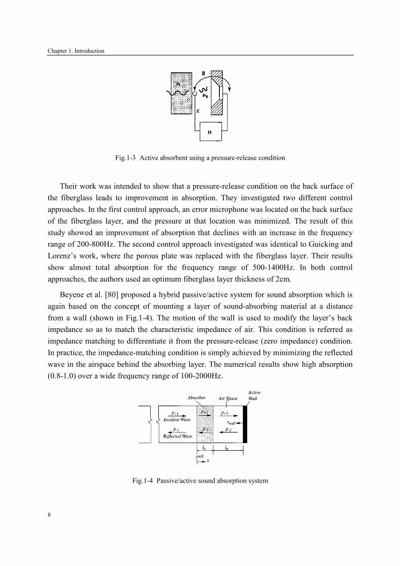
over the frequency range 100-600Hz. Thereafter, Thenail [79] investigated an active system
that included a fiberglass absorbing layer backed by an air cavity terminated with an active
surface (shown in Fig.1-3).
Chapter 1. Introduction
8
Fig.1-3 Active absorbent using a pressure-release condition
Their work was intended to show that a pressure-release condition on the back surface of
the fiberglass leads to improvement in absorption. They investigated two different control
approaches. In the first control approach, an error microphone was located on the back surface
of the fiberglass layer, and the pressure at that location was minimized. The result of this
study showed an improvement of absorption that declines with an increase in the frequency
range of 200-800Hz. The second control approach investigated was identical to Guicking and
Lorenz’s work, where the porous plate was replaced with the fiberglass layer. Their results
show almost total absorption for the frequency range of 500-1400Hz. In both control
approaches, the authors used an optimum fiberglass layer thickness of 2cm.
Beyene et al. [80] proposed a hybrid passive/active system for sound absorption which is
again based on the concept of mounting a layer of sound-absorbing material at a distance
from a wall (shown in Fig.1-4). The motion of the wall is used to modify the layer’s back
impedance so as to match the characteristic impedance of air. This condition is referred as
impedance matching to differentiate it from the pressure-release (zero impedance) condition.
In practice, the impedance-matching condition is simply achieved by minimizing the reflected
wave in the airspace behind the absorbing layer. The numerical results show high absorption
(0.8-1.0) over a wide frequency range of 100-2000Hz.
Fig.1-4 Passive/active sound absorption system

Chapter 1. Introduction
9
Furstoss and his colleagues [81] investigated and tested two different active systems for
controlling surface normal impedance in an anechoic chamber (shown in Fig.1-5). In the first,
direct impedance control simultaneously processes the acoustic pressure and velocity near a
loudspeaker membrane which was driven by the controller in order to assign a prescribed
impedance value for both normal and oblique plane waves. The result showed reflected waves
can be cancelled over the 150-500Hz frequency wave. In the second impedance control
procedure active control of the impedance at the rear face of a porous material panel was used
so that the front face impedance took on a desired value. Results show that pressure release at
the back face of an appropriately chosen porous panel produced high absorption over wide
ranges of frequency and incidence angle.
Fig.1-5 Experimental schema of active absorber in normal incident
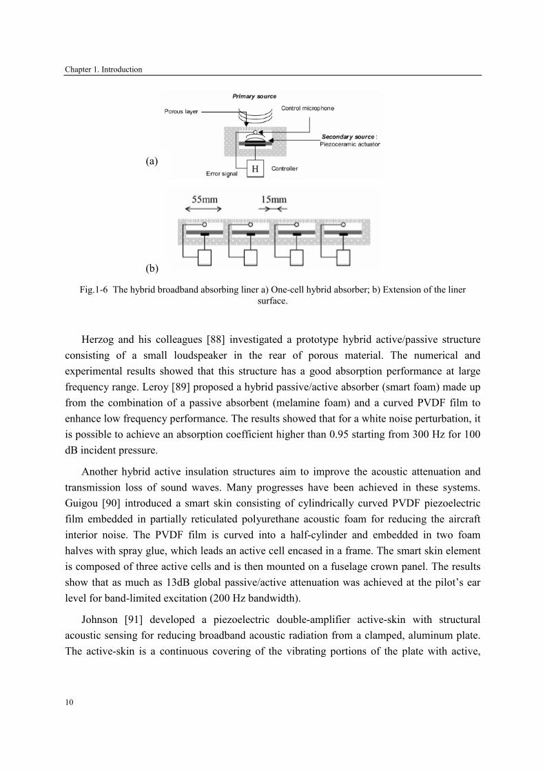
The LMFA, Centre Acoustique, at Ecole Centrale de Lyon has developed over the last ten
years a design of hybrid broadband absorbing liner which combines the passive properties of
absorbent materials and active control [82-87], shown in Fig.1-6. In each cell, the passive part
is considered with the determination of a suitable porous material and the cut-off frequency
separating the active low frequency regime from the passive high frequency one. The active
part is realized by a piezoelectric actuator as secondary source. Several single cells can be
juxtaposed to form a larger active surface. The numerical results show that the combined
passive/active operation can achieve significant noise reductions, between 8dB and about
20dB in flow duct, for velocities up to 50 m/s with a treated area of 0.22 m by 0.055m.
Chapter 1. Introduction
10
Fig.1-6 The hybrid broadband absorbing liner a) One-cell hybrid absorber; b) Extension of the liner
surface.
Herzog and his colleagues [88] investigated a prototype hybrid active/passive structure
consisting of a small loudspeaker in the rear of porous material. The numerical and
experimental results showed that this structure has a good absorption performance at large
frequency range. Leroy [89] proposed a hybrid passive/active absorber (smart foam) made up
from the combination of a passive absorbent (melamine foam) and a curved PVDF film to
enhance low frequency performance. The results showed that for a white noise perturbation, it
is possible to achieve an absorption coefficient higher than 0.95 starting from 300 Hz for 100
dB incident pressure.
Another hybrid active insulation structures aim to improve the acoustic attenuation and
transmission loss of sound waves. Many progresses have been achieved in these systems.
Guigou [90] introduced a smart skin consisting of cylindrically curved PVDF piezoelectric
film embedded in partially reticulated polyurethane acoustic foam for reducing the aircraft
interior noise. The PVDF film is curved into a half-cylinder and embedded in two foam
halves with spray glue, which leads an active cell encased in a frame. The smart skin element
is composed of three active cells and is then mounted on a fuselage crown panel. The results
show that as much as 13dB global passive/active attenuation was achieved at the pilot’s ear
level for band-limited excitation (200 Hz bandwidth).
Johnson [91] developed a piezoelectric double-amplifier active-skin with structural
acoustic sensing for reducing broadband acoustic radiation from a clamped, aluminum plate.
The active-skin is a continuous covering of the vibrating portions of the plate with active,
(a)
(b)
Chapter 1. Introduction
11
independently controllable piezoelectric, double-amplifier elements. The results indicate that
total radiated power attenuation in excess of 10dB may be achieved between 250 and 750Hz.
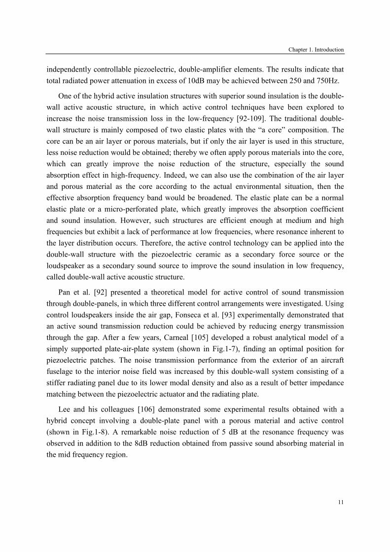
One of the hybrid active insulation structures with superior sound insulation is the double-
wall active acoustic structure, in which active control techniques have been explored to
increase the noise transmission loss in the low-frequency [92-109]. The traditional double-
wall structure is mainly composed of two elastic plates with the “a core” composition. The
core can be an air layer or porous materials, but if only the air layer is used in this structure,
less noise reduction would be obtained; thereby we often apply porous materials into the core,
which can greatly improve the noise reduction of the structure, especially the sound
absorption effect in high-frequency. Indeed, we can also use the combination of the air layer
and porous material as the core according to the actual environmental situation, then the
effective absorption frequency band would be broadened. The elastic plate can be a normal
elastic plate or a micro-perforated plate, which greatly improves the absorption coefficient
and sound insulation. However, such structures are efficient enough at medium and high
frequencies but exhibit a lack of performance at low frequencies, where resonance inherent to
the layer distribution occurs. Therefore, the active control technology can be applied into the
double-wall structure with the piezoelectric ceramic as a secondary force source or the
loudspeaker as a secondary sound source to improve the sound insulation in low frequency,
called double-wall active acoustic structure.
Pan et al. [92] presented a theoretical model for active control of sound transmission
through double-panels, in which three different control arrangements were investigated. Using
control loudspeakers inside the air gap, Fonseca et al. [93] experimentally demonstrated that
an active sound transmission reduction could be achieved by reducing energy transmission
through the gap. After a few years, Carneal [105] developed a robust analytical model of a
simply supported plate-air-plate system (shown in Fig.1-7), finding an optimal position for
piezoelectric patches. The noise transmission performance from the exterior of an aircraft
fuselage to the interior noise field was increased by this double-wall system consisting of a
stiffer radiating panel due to its lower modal density and also as a result of better impedance
matching between the piezoelectric actuator and the radiating plate.
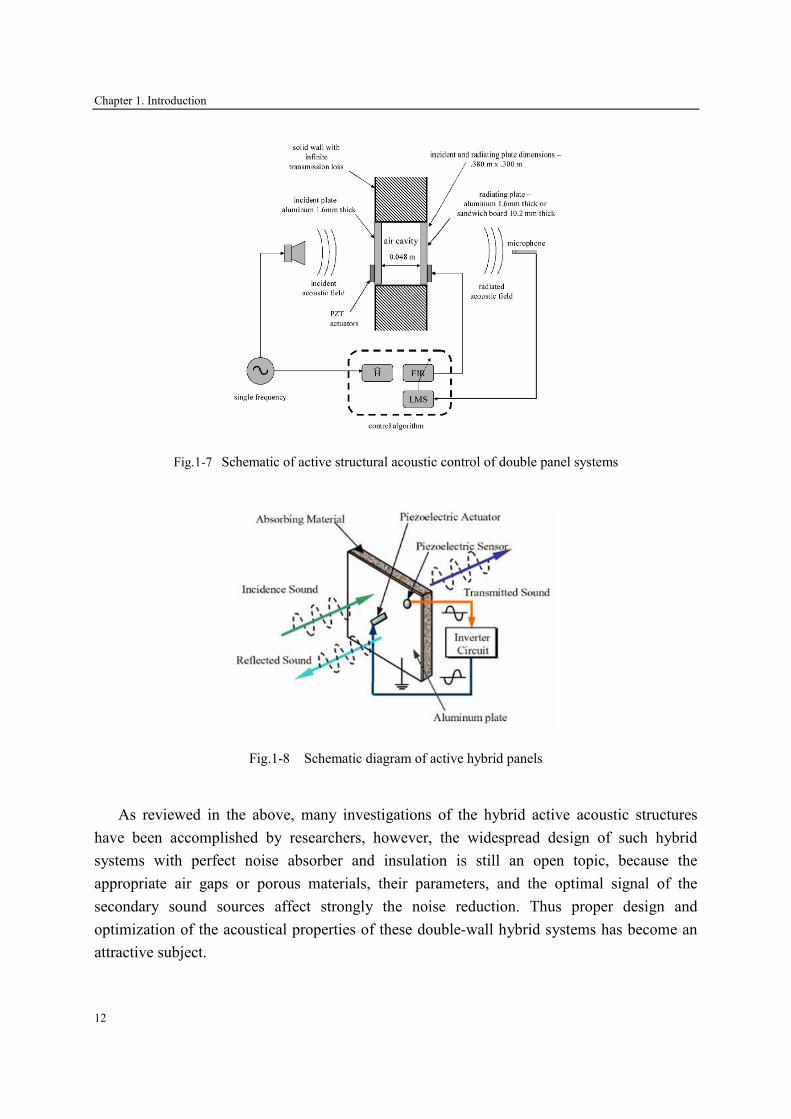
Lee and his colleagues [106] demonstrated some experimental results obtained with a
hybrid concept involving a double-plate panel with a porous material and active control
(shown in Fig.1-8). A remarkable noise reduction of 5 dB at the resonance frequency was
observed in addition to the 8dB reduction obtained from passive sound absorbing material in
the mid frequency region.
Chapter 1. Introduction
12
Fig.1-7 Schematic of active structural acoustic control of double panel systems
Fig.1-8 Schematic diagram of active hybrid panels
As reviewed in the above, many investigations of the hybrid active acoustic structures
have been accomplished by researchers, however, the widespread design of such hybrid
systems with perfect noise absorber and insulation is still an open topic, because the
appropriate air gaps or porous materials, their parameters, and the optimal signal of the
secondary sound sources affect strongly the noise reduction. Thus proper design and
optimization of the acoustical properties of these double-wall hybrid systems has become an
attractive subject.

Chapter 1. Introduction
13
1.2 Research method
1.2.1 Mathematical methods for modeling hybrid active acoustic structure
In real applications, in order to know the acoustical properties of a certain multilayer
system easily and rapidly, prediction is often needed instead of direct measurement. Many
theories have been developed for multilayer systems [110-124]. In most cases, feasible
prediction via a so-called transfer matrix method [114-124] is often used. This method is
based on a theory, which says that the relation between the pressure and bulk flow of two
ends of a sound propagating route can be expressed by a matrix. The transfer matrix can be
looked up on as an inherent property of a material because of its invariance. If the transfer
matrix of a material is known, most of the acoustical properties of the material can be
obtained. Because of the continuity of sound pressure and velocity, the matrices of all the
component layers can be combined together into a total matrix which can be used to predict
the acoustical properties of multilayer systems. The type of transfer matrix is determined by
such factors as physical properties of the material, boundary conditions, selected state
variables and so on.
When multilayer active acoustic structures are passive, analytical absorption coefficient
and acoustic insulation can be deduced from the transfer matrix method. This matrix is easily
deduced from elementary transfer matrices associated with each element or interface of the
passive sandwich under consideration. Kwon and his colleague [120, 125] estimated the
absorption coefficient of the perforated panel systems from the overall transfer matrix
obtained by multiplying unit transfer matrices. The proposed transfer matrix method is
confirmed by comparing the estimated absorption coefficient with the measured value. Lee
[123] developed a modified transfer matrix method for evaluating normal incidence sound
transmission loss of multilayer solid materials by taking advantage of thin plate theory and the
mass law effect. The predicted results were comparable to the direct measurements via a
standing wave tube method.
However, when active acoustic structures are hybrid (including active control), the
transfer matrix method is not suitable to model the problem since calculations become
complicate. On the other hand, it has been shown by Aböm [126-128] that the scattering
matrix theory is a very suitable formulation for predicting acoustical proprieties of both
passive and active discontinuities in duct systems. This scattering matrix is used to predict
acoustic performances of passive two-port discontinuities in ducts such as silencers, mufflers
[126] and also of two-port sources [127] for example: pump, fans having one inlet and one
outlet opening. Yet, the scattering-matrix method gives the best basic description of wave
interaction problem (anechoic transmission and reflection on both sides of the discontinuity,
Chapter 1. Introduction
14
symmetry...). It can be used even for modeling complex networks including several kinds of
discontinuities [128].
Nevertheless, the scattering matrix method is not a perfect method when the hybrid active
acoustic structure having the porous material which is elastic or coupled with an elastic plate.
Due to the biphasic nature of porous material, the characterization of its acoustical behavior is
crucial to predict the acoustic performance of the hybrid systems. For high-frequency
excitation of porous materials attached to a rigid wall structure, the porous material is often
considered as an equivalent fluid with effective density and bulk modulus [129]. This type of
modeling applies to porous materials having a rigid skeleton, i.e., motionless or a very limp
skeleton. In this case, only one compression wave propagates in the air-saturated medium, and
five important parameters are needed to define the equivalent density and the equivalent
impedance: porosity, resistivity, tortuosity, viscous length, and thermal length [130].
For low-frequency excitation, or porous materials attached to an elastic plate, the porous
material is subject to three basic waves propagating simultaneously in the solid and fluid
phase: one shearing and two compression waves. In this case, the elasticity of the skeleton
should be considered, and the strong coupling between the solid and fluid phases cannot be
ignored [131-135]. The mechanical behavior of poroelastic materials has been established by
Biot’s theory describing the propagation of elastic waves. For several decades, many works
were made specifically to adapt Biot’s theory to acoustic problems in porous materials [136-
142]. Following these works, the equations of dynamic equilibrium of the porous medium
were solved in terms of the solid and fluid displacements: u describing the displacement of
the solid phase, and U describing the displacement of the fluid phase. The first model [138,
139], motivated by biomedical and geomechanical problems, are based on classical plate
theory with Kirchhoff’s assumptions and the ( , )u U formulation of Biot’s relations. More
recently, Leclaire et al. [140] used the ( , )u U formulation of Biot’s equations to derive two
equations of equilibrium for the porous plate. The main advantages of this model are the
simplicity of the equations, and their capability to be solved under boundary conditions other
than simply-supported edges. This model has been validated by experiments on high density
clamped porous plates [141]. For simple one- or two-dimensional structures, their
vibroacoustic responses can be accurately calculated by the finite element method with the
( , )u U formulation, however, for complex three-dimensional structures, six degrees of freedom
per node are required at least in order to calculate the vibration response, which leads to
cumbersome calculations for large finite element models and spectral analysis.
To alleviate these difficulties, a mixed formulation using the displacement of the solid
phase and the interstitial fluid pressure as variables was proposed by Atalla [143], called the
Chapter 1. Introduction
15
( , )u p formulation, which seems more suitable for large size finite element models and
requires only four degrees of freedom per node. Lately, the strain couplings between the fluid
and solid phases of porous materials have been derived according to the continuity of the
solid phase displacement vector and the interstitial fluid pressure [144]. However, because of
the biphasic nature of porous materials, in the case of broadband source excitation, excessive
computing problems still exist in finite element models, hence, the ( , )u p formulation needs to
be simplified according to the characteristics of solid and fluid media. Dazel [145] proposed a
simplified ( , )u p formulation based on the dominant vibration modes of porous materials;
Bermudez [146] gave a simplified finite element model for porous materials with the non-
viscous and pore-interlinked fluid medium; Batifol [147, 148] deduced the partial differential
equations of porous materials in the Comsol environment based on the ( , )u p formulation.
Etchessahar et al. used the ( , )u p formulation of Biot’s equations in association with the
classical theory of plates to derive two coupled equations of equilibrium of a homogeneous
and isotropic poroelastic plate [149, 150]. This theory is valid in the case of porous materials
as long as the wavelength of the bending waves is much greater than the size of the pores.
Because of these simplified finite element models, the ( , )u p formulation has been widely
used to the sound propagation in porous materials.
1.2.2 Measurement method of hybrid active acoustic structure
When the active acoustic structures or the boundary conditions are very complex and their
acoustical properties can not be calculated by mathematical methods, direct measurement is
an effective approach to predict the transmission loss and absorption. Generally speaking, the
reverberation room method [151] and the standing wave tube method [152] are the two useful
methods which have been widely applied to measure the acoustical properties of a certain
material. In fact, the reverberation room method provides authoritative test results, but it is
not easy to use. This method not only takes time, but also requires some types of equipment
such as reverberation room, high quality microphone etc. Besides, the dimension of the tested
structure should be large enough.
For remedying the drawback of the reverberation room method, the standing wave tube
method which can measure the acoustic property of the small-dimension structures has also
been used widely and adopted as an ISO standard [152]. Apfel et al. [153] developed a new
laboratory method to evaluate the acoustical properties of expandable and other automotive
sealants in the standing wave tube. In the method, ASTM E 1050 [154] absorption
measurement equipment is used along with a new sample holder, a downstream microphone
holder (providing two additional microphone locations) and an anechoic termination. Bolton
et al. [155] described a two-microphone standing wave tube method for evaluating the
Chapter 1. Introduction
16
acoustical properties of homogeneous and isotropic porous materials based on the transfer
matrix method. Zhu Beili et.al [156-158] proposed a four-microphone method to measure
sound transmission loss in the standing wave tube. This method can separate the transmission
wave from the reflected wave in the absorbent ending and raise the precision of the
measurement in the low frequency range.
Nevertheless, the major drawback of the standing wave tube method is that an anechoic
termination is required. In practice, an anechoic termination could be constructed using a long
exhaust tube, high absorbing materials, horn shapes pipes or an active sound anechoic
termination [159]. However, a fully anechoic termination is difficult to be built, particularly
one that is effective at low frequencies. Thus, two alternative measurement approaches are
considered, which do not require an anechoic termination: the two-load method [160] and the
two source-location method [161]. Both methods are realized by measuring acoustic pressures
at four fixed locations, two upstream and two downstream of the tested structure, with a
different load or a random source on both sides of the test tube respectively. Then the four-
pole parameters of the tested structure are calculated by means of a dual-channel FFT
analyzer and use of the time-domain ensemble averaging. Due to the two-load method suffers
from an additional disadvantage in that the two loads may not be sufficiently different at all
frequencies of interest, the two source-location method is much more stable and entirely
independent of the loading terminations.
1.3 Objectives of the thesis
The objective of the thesis is to design a new type of hybrid active acoustic structure
combining the passive absorption properties and the principle of active noise control. It aims
at not only providing perfect acoustical absorption, but also a good insulation in wide
frequency band. This hybrid active acoustic structure consists of an elastic plate, an active
plate and several layers such as air gaps or porous material. The piezoelectric ceramics are
glued to the active plate and the positive/negative voltage is imposed on the piezoelectric
ceramics to make the active plate vibrating as a secondary source. In order to analyze the
acoustic properties (absorption coefficient and transmission loss) of the hybrid active acoustic
structure, the structure model is first established, and the response equations of each layer in
the hybrid active acoustic structure have been set up. Then the boundary conditions between
the layers would be modeled according to the continuity nature of the sound pressure and the
normal velocity. In addition, because of the biphasic of the porous material, the viscous and
thermal effects cannot be neglected when the incident sound wave transmits through the
entrance and exit of the pore in the porous material.
Chapter 1. Introduction
17
The designed hybrid active acoustic structure is applied to eliminate the unwanted noise.
An experimental device, mainly in the assessment of performance of acoustic treatment, has
been established at the LMFA at the Ecole Centrale de Lyon. Optimization of the hybrid
active acoustic structure is thus directly carried out in the test section in order to achieve high
levels of noise reduction. Besides, the multi-cell hybrid active acoustic structure is realized by
juxtaposing several single hybrid cells for eliminating the noise in a large-area domain. In the
multi-cell hybrid structures, the interface between each hybrid cell is rigid or elastic, and each
cell has an error sensor for active control with the objective function of a minimum sound
pressure.
1.4 Structure of the thesis
The structure of this thesis is described as follows.
In chapter 2, the transfer matrix method is applied to analyze the acoustic characteristic of
the double-wall passive acoustic structure. The definition of the transfer matrix and scattering
matrix are given in the acoustic structure, and the relationship between them is also expressed.
Based on the sound propagation principle, the transfer matrix of the elastic plate, the air gap,
the porous material and the interface between each layer are modeled and then deduced to
establish the total transfer matrix of the double-wall structure. Lastly, the absorption
coefficient and transmission loss of the double-wall passive acoustic structure are calculated
and analyzed with some numerical examples.
In chapter 3, the work aims to develop a hybrid active acoustic structure allowing good
acoustic insulation and absorption for a wide frequency range. These hybrid active acoustic
structures combine passive and active means by using passive layers and active plate. The
secondary source is realized by an active plate consisting of two piezoelectric patches bonded
to an elastic thin plate in order to improve acoustic insulation at low and resonances
frequencies. Using the scattering matrix method, the active plate has been completely
described in form of a scattering matrix and a source strength vector which represents
respectively the passive and active proprieties of this plate. In active control, the source
strength vector of the active plate is calculated in order to minimize the sound pressure or
power at the location of the error sensor. The acoustic performances of the hybrid system, the
absorption coefficient and transmission loss, are then deduced from the secondary source
vector and the scattering matrix coefficients of all layers or elements composing this system.
Lastly, the influence factors which affect the acoustic performance of the hybrid system have
been investigated by simulation on different parameters of each layer.
In chapter 4, a finite element model of hybrid active acoustic structure is developed with
the ( , )u p formulation in the Comsol environment. This model has considered the elasticity of
Chapter 1. Introduction
18
the skeleton of the poroelastic material and the strong coupling between the solid and fluid
phases. Besides, the boundary conditions on the coupling surface of the elastic, poroelastic
and air layers were formulated in Comsol modes. The dynamic responses of some hybrid
active acoustic structures have been studied under plane wave excitation, in which
piezoelectric patches are added onto the excited plate behaving as a secondary vibrational
source. The resonance frequencies of these hybrid structures have been calculated by the
scattering matrix method and Comsol environment. The numerical results show that sound
insulation of the hybrid active acoustic structure can be improved at resonance frequencies
with active control.
In chapter 5, the work aims at applying the two source-location method based on the
scattering matrix for measuring the acoustic performance of the hybrid active acoustic
structure, using a dSPACE-DS1103 controller implemented with Simulink for finding the
optimal signal of the secondary sound source in active control. The measurement was carried
out in a rectangular tube, and no anechoic termination is required. The reflection and
transmission coefficients of each layer in the hybrid active acoustic structure are determined.
Besides, the acoustic performance of some hybrid active acoustic structure are measured and
compared to the numerical data. Their transmission losses are improved by active control,
which agrees well with the numerical results in the scattering matrix method and the finite
element method with Comsol software.
In chapter 6, the multi-cell hybrid active acoustic structure concept is proposed by
compositing single hybrid cells for controlling the noise in a large-area domain. In the multi-
cell hybrid active acoustic structure, the interface between each hybrid cell can be rigid or
elastic. Each cell has an error sensor for active control and a minimum sound power can be
used as the objective function. The acoustic absorption and transmission performance of these
multi-cell hybrid systems have been calculated with the mixed ( , )u p formulation and finite
element method in Comsol environment.
In chapter 7, we give the conclusions and perspectives.
Chapter 2 Acoustic performance analysis of double-wall passive acoustic structure by transfer matrix method
19
Chapter 2
Acoustic performance analysis of double-wall
passive acoustic structure by transfer matrix
method
The transfer matrix method is a simple method for static, dynamic and stability analysis of
structures, and it means that the relationship between input and output of the linear system can
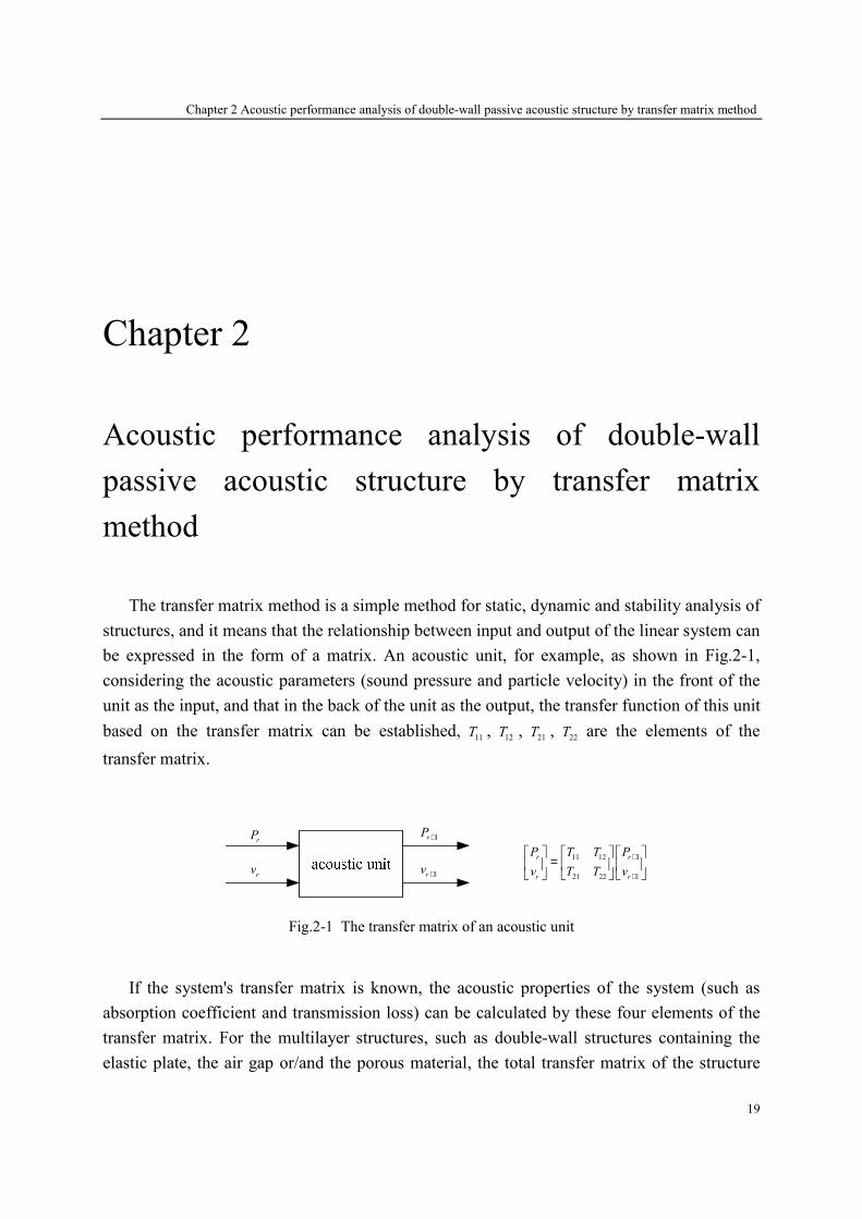
be expressed in the form of a matrix. An acoustic unit, for example, as shown in Fig.2-1,
considering the acoustic parameters (sound pressure and particle velocity) in the front of the
unit as the input, and that in the back of the unit as the output, the transfer function of this unit
based on the transfer matrix can be established, 11
T , 12
T , 21
T , 22
T are the elements of the
transfer matrix.
rP
rv
1rP +
1rv +
11 12 1
21 22 1
r r
r r
P T T P
v T T v
+
+
=
Fig.2-1 The transfer matrix of an acoustic unit
If the system's transfer matrix is known, the acoustic properties of the system (such as
absorption coefficient and transmission loss) can be calculated by these four elements of the
transfer matrix. For the multilayer structures, such as double-wall structures containing the
elastic plate, the air gap or/and the porous material, the total transfer matrix of the structure

Chapter 2 Acoustic performance analysis of double-wall passive acoustic structure by transfer matrix method
20
can be obtained by multiplying the transfer matrix of each layer, because of the continuity of
sound pressure and velocity. Worthy of note is that the transfer matrix is derived based on the
physical characteristics of the structure, and hence it depends on only the physical properties
of the structure and boundary conditions, and is independent of external environment. In
addition to the transfer matrix, the acoustic characteristics of the structure can also analyzed
by the scattering matrix, the impedance matrix, and the admittance matrix.
This chapter aims to analyze the acoustic characteristic of the double-wall passive
acoustic structure by the transfer matrix method. Firstly, the definition of the transfer matrix
and scattering matrix are given in the acoustic structure, and the relationship between them is
also expressed. Based on the sound propagation principle, the transfer matrix of the elastic
plate, the air gap, the porous material and the interface between each layer are modeled and
then deduced to establish the total transfer matrix of the double-wall structure. Lastly, the
absorption coefficient and transmission loss of the double-wall passive acoustic structure are
calculated and analyzed with some numerical examples.
2.1 The acoustic parameters of double-wall passive structures
The acoustic properties of the double-wall passive structure excited by sound waves can
be described by four matrices: the transfer matrix, the scattering matrix, the impedance matrix
and the admittance matrix. These four matrices depend on the characteristic of the structures,
and are independent of the sound source location and intensity. Besides, the linear
relationship exists between each other. In this section, the sound pressure and the normal
particle velocity are firstly expressed on both sides of double-wall passive structure. Then, the
definitions of the transfer matrix, the scattering matrix, the impedance matrix and the
admittance matrix and the relationship between each matrix are described. Lastly, the
transmission loss and the absorption coefficient of the structure derived from the transfer
matrix.
z +
θ
1P +
1P −
2P +
Side 2Side1
1 2z z• •
2P −
∞
Fig.2-2 The schematic of a passive system with infinite laterally dimensions
Chapter 2 Acoustic performance analysis of double-wall passive acoustic structure by transfer matrix method
21
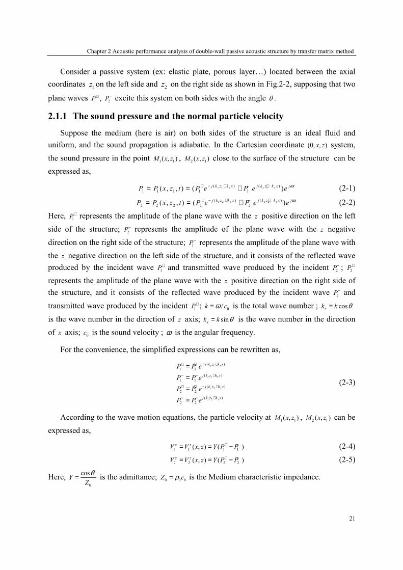
Consider a passive system (ex: elastic plate, porous layer…) located between the axial
coordinates 1z on the left side and 2z on the right side as shown in Fig.2-2, supposing that two
plane waves 1
P+ , 2
P− excite this system on both sides with the angle θ .
2.1.1 The sound pressure and the normal particle velocity
Suppose the medium (here is air) on both sides of the structure is an ideal fluid and
uniform, and the sound propagation is adiabatic. In the Cartesian coordinate (0, , )x z system,
the sound pressure in the point 1 1( , )M x z ,
2 1( , )M x z close to the surface of the structure can be
expressed as,
1 1( ) ( )
1 1 1 1 1( , , ) ( )z x z xj k z k x j k z k x j tP P x z t P e P e e ω− + ++ −= = + (2-1)
2 2( ) ( )
2 2 2 2 2( , , ) ( )z x z xj k z k x j k z k x j tP P x z t P e P e e ω− + ++ −= = + (2-2)
Here, 1
P+ represents the amplitude of the plane wave with the z positive direction on the left
side of the structure; 2
P− represents the amplitude of the plane wave with the z negative
direction on the right side of the structure; 1P− represents the amplitude of the plane wave with
the z negative direction on the left side of the structure, and it consists of the reflected wave
produced by the incident wave 1P+ and transmitted wave produced by the incident 2P− ; 2P+
represents the amplitude of the plane wave with the z positive direction on the right side of
the structure, and it consists of the reflected wave produced by the incident wave 2P− and
transmitted wave produced by the incident 1P+ ; 0/k cω= is the total wave number ; cosz
k k θ=
is the wave number in the direction of z axis; sinx
k k θ= is the wave number in the direction
of x axis; 0c is the sound velocity ; ω is the angular frequency.
For the convenience, the simplified expressions can be rewritten as,
1
1
2
2
( )
1 1
( )
1 1
( )
2 2
( )
2 2
z x
z x
z x
z x
j k z k x
j k z k x
j k z k x
j k z k x
P P e
P P e
P P e
P P e
− ++ +
+− −
− ++ +
+− −
=
=
=
=
(2-3)
According to the wave motion equations, the particle velocity at 1 1( , )M x z ,
2 1( , )M x z can be
expressed as,
1 1 1 1( , ) ( )z zV V x z Y P P+ −= = − (2-4)
2 2 2 2( , ) ( )z zV V x z Y P P+ −= = − (2-5)
Here, 0
cosY
Z
θ= is the admittance; 0 0 0
Z cρ= is the Medium characteristic impedance.

Chapter 2 Acoustic performance analysis of double-wall passive acoustic structure by transfer matrix method
22
2.1.2 The acoustic matrices
1. The transfer matrix
The transfer matrix T reflects the relationship between input and output of linear system.
For the double-wall structure, considering the acoustic parameters (sound pressure and
particle velocity) in the front of the structure as the input, and that in the back of the structure
as the output, the transfer function of this structure based on the transfer matrix can be
established and expressed as,
11 121 2
21 221 2
,z z
T TP P
T TV V
= ⋅ =
T T (2-6)
Here, 11
T , 12
T , 21
T , 22
T are the elements of the transfer matrix.
2. The scattering matrix
When linear theory is valid, the acoustical behavior of this system can be described
completely by its scattering matrix D which gives linear relationships between the incoming
pressure wave vector 1 2
T
P P+ − and the outgoing pressure wave vector 1 2
T
P P− + :
11 121 1
21 222 2
,D DP P
D DP P
− +
+ −
= ⋅ =
D D (2-7)
This matrix D is independent of the upstream and the downstream acoustic conditions and
is filled by four coefficients, and the physical meaning of each coefficient is as follows:11
D
and 21
D represents respectively anechoic reflection and transmission coefficients associated
with the left side incoming waves; 22
D and 12
D represents respectively anechoic reflection and
transmission coefficients associated with the right side incoming waves. The superscript ‘+’
and ‘-’ represent the positive and negative direction of z axis respectively. If the structure is
symmetry, and the mediums on both sides of the structure are same, we have,
11 22D D= ,
12 21D D= (2-8)
3. The impedance matrix and the admittance matrix
The impedance matrix Z reflects the relationship between the sound pressure and the
normal particle velocity on both sides of the structure, defined as:
1 11 121
2 21 222
,z
z
P Z ZV
P Z ZV
= ⋅ =
Z Z (2-9)
Therefore, the inverse of the impedance matrix is the admittance matrix Y , expressed as,

Chapter 2 Acoustic performance analysis of double-wall passive acoustic structure by transfer matrix method
23
1 11 121
2 21 222
,z
z
P Y YV
P Y YV
= ⋅ =
Y Y (2-10)
Seen from the above definition, the scattering matrix is the most direct and clear way to
describe the acoustic characteristic of double-wall structure. Its elements directly give the
reflection and transmission coefficients under the positive and negative directions of the
incident sound wave. Based on the scattering matrix, we can deduce the energy dissipation of
the structure, including the transmission loss, the absorption coefficient which directly reflects
of the acoustic properties of the structure. Meanwhile, the four matrices are directly
determined by the inherent properties of the structure, and independent of the sound source
location. Because of the linear relationship between each matrix, when one of the matrices is
known, the others can be derived easily.
2.1.3 The transformation of the matrices
1. Transformation between the transfer matrix and the scattering matrix
Eq. (2-6) can be written as,
1 11 2 12 2
1 21 2 22 2
z
z
P T P T V
V T P T V
= +
= + (2-11)
Substituting Eq. (2-1) ~ (2-5) into Eq. (2-6), we get,
( ) ( )( ) ( )
1 1 11 2 2 12 2 2
21
1 1 2 2 22 2 2
P P T P P T Y P P
TP P P P T P P
Y
+ − + − + −
+ − + − + −
+ = + + −
− = + + − (2-12)
Eq. (2-12) can be expressed as follows,
1 1 2 2P P X P X P+ − + + − −+ = + (2-13)
1 1 2 2P P W P W P+ − + + − −− = + (2-14)
Here
11 12X T YT± = ± and 21
22
TW T
Y
± = ± (2-15)
After simply mathematical operation with Eq. (2-13) and (2-14), we have,
( )( )
( )( )1 1 2
X W X W W XP P P
X W X W
+ + + − + −− + −
+ + + +
− −= +
+ + (2-16)
2 1 2
2 X WP P P
X W X W
− −+ + −
+ + + +
+= −+ +
(2-17)

Chapter 2 Acoustic performance analysis of double-wall passive acoustic structure by transfer matrix method
24
Eq. (2-16) and (2-17) can be written in a matrix, and the four coefficients of the scattering
matrix are expressed in terms of the transfer matrix,
11 121 1
21 222 22 2
.D DP P
D DP P
− +
+ −×
=
(2-18)
Here
12
X W W XD
X W
+ − + −
+ +
−=+
(2-19)
11
X WD
X W
+ +
+ +
−=+
(2-20)
21
2D
X W+ +=
+ (2-21)
22
X WD
X W
− −
+ +
+= −+
(2-22)
2. Transformation between the transfer matrix and the impedance matrix
Eq. (2-6) can be written as:
1 1 1 1 12 2
z zP Z V Z V= + (2-23)
2 21 1 22 2
z zP Z V Z V= + (2-24)
After simply mathematical operation with Eq. (2-23) and (2-24), we have,
11 22
1 2 12 2
21 21
zZ ZP P Z V
Z Z
= + −
(2-25)
22
1 2 2
21 21
1 zZV P V
Z Z= − (2-26)
Eq. (2-25) and (2-26) can be written in a matrix, and compared to Eq. (2-6), we get,
11
11
21
ZT
Z= 22
12 12
21
ZT Z
Z= − (2-27)
21
21
1T
Z= 22
22
21
ZT
Z= − (2-28)
2.1.4 The acoustic properties of the double-wall structure
1. Transmission loss
When the structure is excited only by the incident wave from the left side, the
transmission loss (1)
TL can be obtained by the scattering matrix element 21
D ,

Chapter 2 Acoustic performance analysis of double-wall passive acoustic structure by transfer matrix method
25
(1) 2
21
110logTL
D
=
(2-29)
When the structure is excited only by the incident wave from the right side, the
transmission loss (2)
TL can be obtained by the scattering matrix element 12
D ,
(2) 2
12
110logTL
D
=
(2-30)
2. Absorption coefficient
When the structure is excited only by the incident wave from the left side, the absorption
coefficient (1)
α can be obtained by the scattering matrix element 11
D ,
2
(1) 111 Dα = − (2-31)
When the structure is excited only by the incident wave from the right side, the absorption
coefficient (2)
α can be obtained by the scattering matrix element 22
D ,
2
(2) 221 Dα = − (2-32)
3. Loss power
The energy loss power loss
W of the double-wall structure is defined as the difference
between the input power in
W and the radiating power rad
W ,
lo ss in radW W W= − (2-33)
According to the definition of the sound power, we have,
1 2( , , ) ( , , )z z z
in in in in
S S S
W I dS I z x y dS I z x y dS= = +∫ ∫ ∫ (2-34)
1 2( , , ) ( , , )z z z
rad rad rad rad
S S S
W I dS I z x y dS I z x y dS= = +∫ ∫ ∫ (2-35)
Here, 1
( , , )z
inI z x y ,
2( , , )z
inI z x y represent respectively the normal incident sound intensity at the
points 1 1( , , )M z x y and
2 2( , , )M z x y ;
1( , , )z
radI z x y ,
2( , , )z
radI z x y represent respectively the normal
radiating sound intensity at the points 1 1( , , )M z x y and
2 2( , , )M z x y .
According to the definition of the sound intensity, the normal sound intensity can be
expressed by the normal particle velocity and the acoustic pressure,
( )*1Re
2
z zI PV= (2-36)
Hence,
Chapter 2 Acoustic performance analysis of double-wall passive acoustic structure by transfer matrix method
26
( )2 2
1 2 1 2
0 0
cos( )( , , ) ( , , )
2
z z z
in in inI I z x y I z x y P Pc
θρ
+ −= + = + (2-37)
( )2 2
1 2 1 2
0 0
cos( )( , , ) ( , , )
2
z z z
rad rad radI I z x y I z x y P Pc
θρ
− += + = + (2-38)
In the plane wave excited, the normal sound intensity does not change with x, y,
( )2 22
1 2
z
in inW S I X P P+ −= ⋅ = + (2-39)
( )2 22
1 2
z
rad radW S I X P P− += ⋅ = + (2-40)
Here, 0 0
cos( )
2X S
c
θρ
= ⋅ ; S ab= is the cross-section area of the double-wall structure.
With some mathematical operation, in
W and rad
W can be rewritten as,
H
in in inW = ×Π Π (2-41)
H
rad rad radW = ×Π Π (2-42)
Here, 1 2
T
in X P P− + = ⋅ Π ; 1 2
T
rad X P P+ − = ⋅ Π ; Subscript H is the conjugate transpose.
Substituting Eq. (2-41) ~ (2-42) into Eq. (2-33), we get,
H H
loss in in rad radW = × − ×Π Π Π Π (2-43)
According to the definition of the scattering matrix, we have,
1 1
2 2
rad in
P P
P P
− +
+ −
= ⋅ ⇒ = ⋅
D Π D Π (2-44)
Substituting Eq. (2-44) into Eq. (2-43), we get,
( )H
loss in inW = − ⋅Π I H Π (2-45)
Here, H= ⋅H D D ; I is an unit matrix.
Obviously, H is a positive definite matrix, then an unit matrix U can make
1
2
0
0
Hλ
λ
= ⋅ ⋅
H U U (2-46)
Here, 1
λ , 2
λ are the eigenvalues of the matrix H ; U is the eigenvector of the matrix H .
And
H= ⋅I U U (2-47)
Substituting Eq. (2-46) and (2-47) into Eq. (2-45), we get,

Chapter 2 Acoustic performance analysis of double-wall passive acoustic structure by transfer matrix method
27
1
2
1 0
0 1
H H
loss in inWλ
λ−
= − Π U U Π (2-48)
Defining
H
in=d U Π (2-49)
Then
(1 ) , 1, 2H
loss jW diag jλ = − = d d (2-50)
Eq. (2-50) can be rewritten as,
22
1
loss j j
j
W dξ=
=∑ , 1j j
ξ λ= − (2-51)
Defining with decibel (dB),
10log in
loss
rad
WW
W
=
(2-52)
2 2
1 2
2 2
1 1 2 2
10logloss
d dW
d dλ λ
+ = +
(2-53)
Eq. (2-53) means that if 1,2
1j
λ = < , the double-wall structure has energy dissipation; if
1,21
jλ = = , it has not energy dissipation.
2.2 The derivations of the transfer matrix
This section presents the transfer matrix of the air layer, the porous material, the elastic
plate and the interface between them. Besides, the total transfer matrices of some multilayer
systems are given.
2.2.1 The transfer matrix of air layer
A normal plane wave transmits into an air layer with the thickness l (seeing in Fig.2-3),
the acoustic waves I and R at the point 1
M respectively are the incident and reflected waves
along the z direction. 1
P , 1
v represent the total sound pressure and normal velocity at the
point 1
M ; 2
P , 2
v represent the total sound pressure and normal velocity at the point 2
M .
When the acoustic wave transmits into the air layer from point 1
M to point 2
M , we have:
1
1
0
1( )
P I R
v I RZ
= + = −
(2-54)
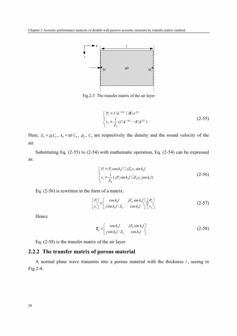
Chapter 2 Acoustic performance analysis of double-wall passive acoustic structure by transfer matrix method
28
Fig.2-3 The transfer matrix of the air layer
0 0
0 0
2
2
0
1( )
jk l jk l
jk l jk l
P I e R e
v I e R eZ
−
−
= ⋅ + ⋅ = ⋅ − ⋅
(2-55)
Here, 0 0 0
Z Cρ= , 0 0
/k Cω= , 0
ρ , 0
C are respectively the density and the sound velocity of the
air.
Substituting Eq. (2-55) to (2-54) with mathematic operation, Eq. (2-54) can be expressed
as:
1 2 0 0 2 0
1 2 0 0 2 0
0
cos sin
1( sin cos )
P P k l jZ v k l
v jP k l Z v k lZ
= + = +
(2-56)
Eq. (2-56) is rewritten in the form of a matrix:
0 0 01 2
0 0 01 2
cos sin
sin / cos
k l jZ k lP P
j k l Z k lv v
= ⋅
(2-57)
Hence
0 0 0
0 0 0
cos sin
sin / cos
k l jZ k l
j k l Z k l
=
aT (2-58)
Eq. (2-58) is the transfer matrix of the air layer.
2.2.2 The transfer matrix of porous material
A normal plane wave transmits into a porous material with the thickness l , seeing in
Fig.2-4.

Chapter 2 Acoustic performance analysis of double-wall passive acoustic structure by transfer matrix method
29
Fig.2-4 The transfer matrix of the porous material
Suppose the porous material is rigid, its transfer matrix can be written as Eq. (2-59) by
changing the impedance of the air 0
Z into the impedance of the porous material c
Z , according
to Lafarge-Allard’s theory [130].
cos sin
sin / cos
c c c
c c c
k l jZ k l
j k l Z k l
=
poroT (2-59)
Here, c
Z , c
k are the impedance and wave number of the porous material respectively, detailed
as follows. Eq. (2-59) is the transfer matrix of the porous material.
Herein, the porous material is assumed to behave like a visco-thermal equivalent fluid and
supposed to have a rigid frame, either because of its very high density or elasticity modulus or
because of its working conditions (when placed on a rigid wall for instance). In this situation
the acoustic waves may only propagate in the air contained in the pores of the material. In the
reason of thermal and viscous effects occurring in the pores of the medium, some acoustic
wave is diffused in heat and sound energy is then absorbed. For obtaining the impedance c
Z
and the wave number c
k of the porous medium, Lafarge-Allard’s theory [130] requires five
intrinsic invariant and independent parameters which are defined below.
When a porous material with fixed thickness e is submitted to a difference of static
pressure 2 1
P P P∆ = − , and a macroscopic flow of average velocity v appears through the
material, the resistivity is defined by the ratio of the static pressure difference to the product
of the velocity and the thickness of the porous sample (Darcy’s law):
P
veσ ∆= (2-60)
The porosity of a porous material is the ratio of the volume of fluid contained in the pores
fluidVol to the total volume of the material
totVol :

Chapter 2 Acoustic performance analysis of double-wall passive acoustic structure by transfer matrix method
30
fluid
tot
Vol
Volφ = (2-61)
The tortuosity is a dimensional quantity which takes into account the sinuous fluid paths
through the porous material.
2
2
V
V
v dV
vdV
α∞ = ∫
∫ (2-62)
Here v is the microscopic velocity and V is a homogenization volume of the material.
The viscous characteristic length Λ has been introduced by Johnson [163] in order to
establish a new expression of the effective density taking into account the high frequency
viscous and inertial effects.
1/ 2
8s
α ηφσ
∞ Λ =
(2-63)
The thermal characteristic length ′Λ , which has been defined by Champoux and Allard
[164], describes the thermal exchanges between the material frame and the pore saturating
fluid.
1/ 2
8s
α ηφσ
∞ ′ ′Λ =
(2-64)
Here s and s′ are the shape factors, η is the dynamic viscosity of air.
The effective density and bulk modulus frequency dependences in the Lafarge-Allard’s
theory [130] are expressed as:
1/ 22
0
0 2 2 2
0
4( ) 1 1
e
j
j
α ηρ ωσφρ ω α ρωρ α σ φ
∞∞
∞
= + + Λ
(2-65)
0
11/ 2
2
0
2
0
( )
Pr8( 1) 1 1
16Pr
PK
j
j
γωρ ωηγ γ
ηω ρ
−= ′ Λ − − + + ′Λ
(2-66)
Here Pr=0.702 is Prandtl number and γ is the specific heat ratio.
Hence, in the scattering matrix method, the impedance c
Z and the wave number c
k of the
porous material is calculated by the effective density ( )e
ρ ω and the bulk modulus ( )K ω ,
expressed as:
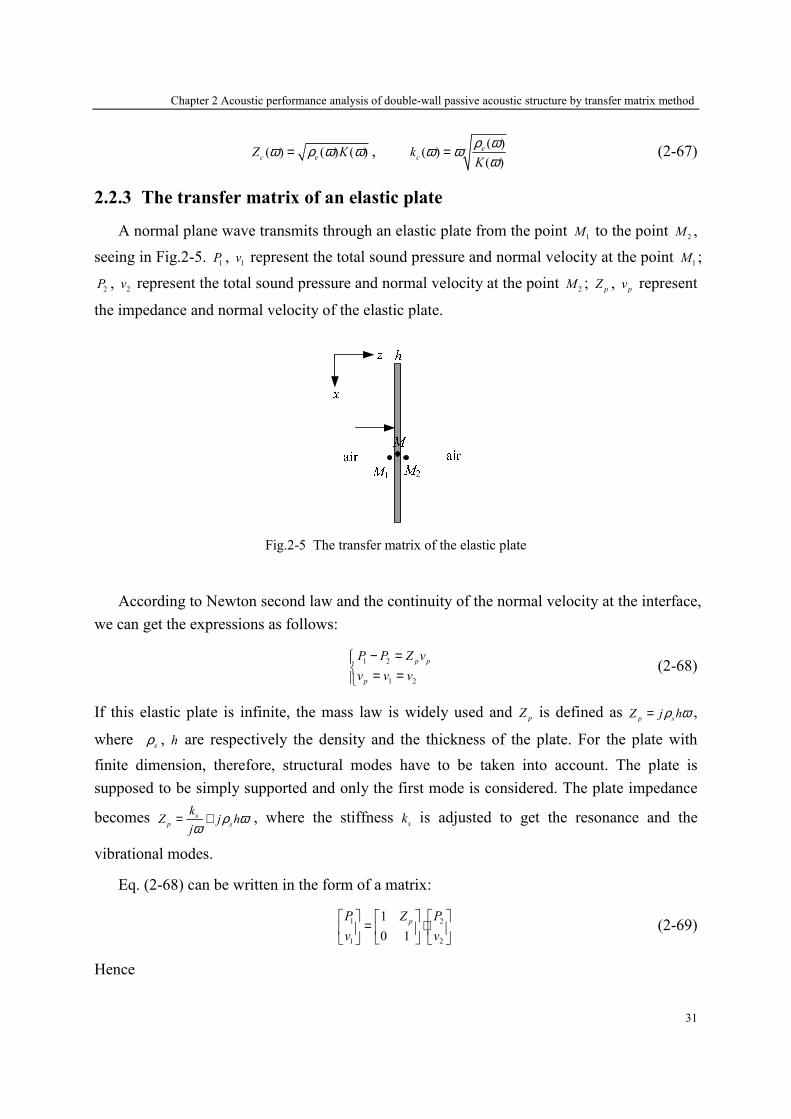
Chapter 2 Acoustic performance analysis of double-wall passive acoustic structure by transfer matrix method
31
( ) ( ) ( )c e
Z Kω ρ ω ω= , ( )
( )( )
e
ck
K
ρ ωω ωω
= (2-67)
2.2.3 The transfer matrix of an elastic plate
A normal plane wave transmits through an elastic plate from the point 1
M to the point 2
M ,
seeing in Fig.2-5. 1
P , 1
v represent the total sound pressure and normal velocity at the point 1
M ;
2P ,
2v represent the total sound pressure and normal velocity at the point
2M ;
pZ ,
pv represent
the impedance and normal velocity of the elastic plate.
Fig.2-5 The transfer matrix of the elastic plate
According to Newton second law and the continuity of the normal velocity at the interface,
we can get the expressions as follows:
1 2
1 2
p p
p
P P Z v
v v v
− = = =
(2-68)
If this elastic plate is infinite, the mass law is widely used and p
Z is defined as p s
Z j hρ ω= ,
where s
ρ , h are respectively the density and the thickness of the plate. For the plate with
finite dimension, therefore, structural modes have to be taken into account. The plate is
supposed to be simply supported and only the first mode is considered. The plate impedance
becomes s
p s
kZ j h
jρ ω
ω= + , where the stiffness
sk is adjusted to get the resonance and the
vibrational modes.
Eq. (2-68) can be written in the form of a matrix:
1 2
1 2
1
0 1
pP PZ
v v
= ⋅
(2-69)
Hence
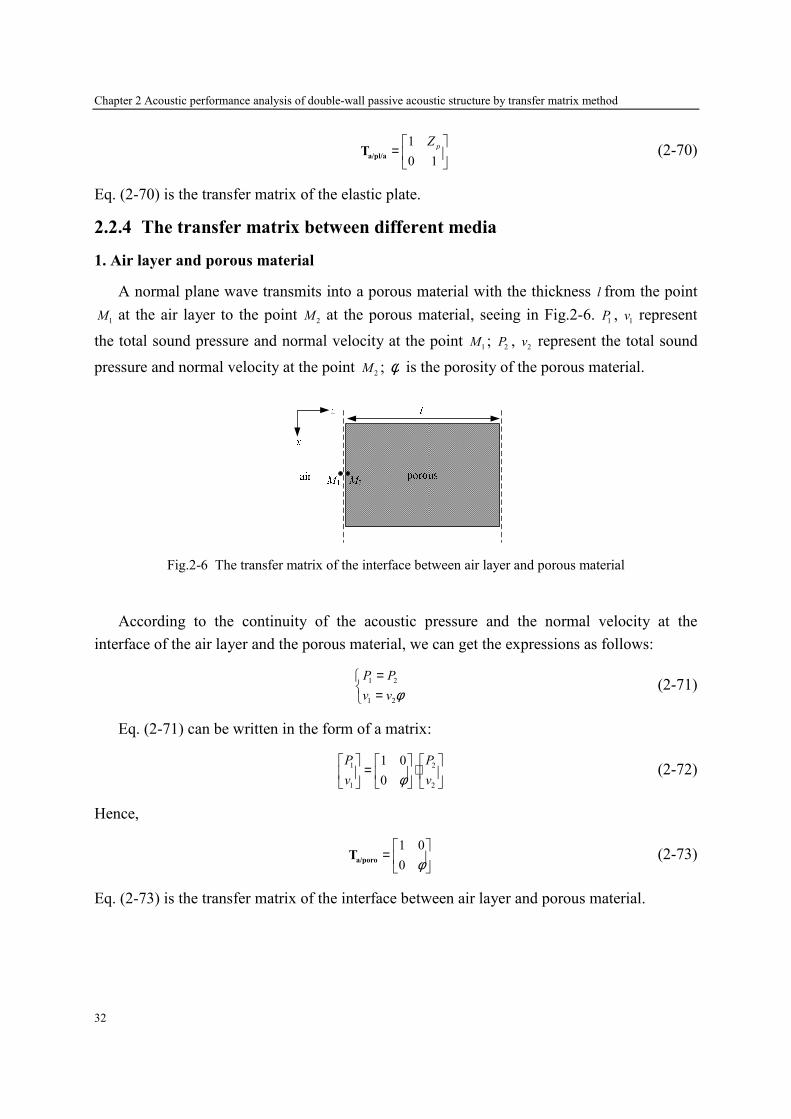
Chapter 2 Acoustic performance analysis of double-wall passive acoustic structure by transfer matrix method
32
1
0 1
pZ =
a/pl/aT (2-70)
Eq. (2-70) is the transfer matrix of the elastic plate.
2.2.4 The transfer matrix between different media
1. Air layer and porous material
A normal plane wave transmits into a porous material with the thickness l from the point
1M at the air layer to the point
2M at the porous material, seeing in Fig.2-6.
1P ,
1v represent
the total sound pressure and normal velocity at the point 1
M ; 2
P , 2
v represent the total sound
pressure and normal velocity at the point 2
M ; φ is the porosity of the porous material.
Fig.2-6 The transfer matrix of the interface between air layer and porous material
According to the continuity of the acoustic pressure and the normal velocity at the
interface of the air layer and the porous material, we can get the expressions as follows:
1 2
1 2
P P
v v φ=
= (2-71)
Eq. (2-71) can be written in the form of a matrix:
1 2
1 2
1 0
0
P P
v vφ
= ⋅
(2-72)
Hence,
1 0
0 φ
=
a/poroT (2-73)
Eq. (2-73) is the transfer matrix of the interface between air layer and porous material.
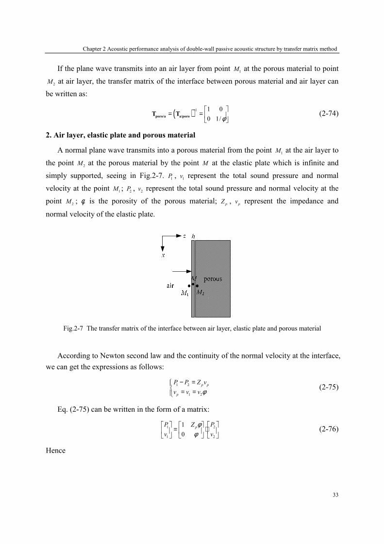
Chapter 2 Acoustic performance analysis of double-wall passive acoustic structure by transfer matrix method
33
If the plane wave transmits into an air layer from point 1
M at the porous material to point
2M at air layer, the transfer matrix of the interface between porous material and air layer can
be written as:
( ) 1 1 0
0 1/φ−
= =
poro/a a/poroT T (2-74)
2. Air layer, elastic plate and porous material
A normal plane wave transmits into a porous material from the point 1
M at the air layer to
the point 2
M at the porous material by the point M at the elastic plate which is infinite and
simply supported, seeing in Fig.2-7. 1
P , 1
v represent the total sound pressure and normal
velocity at the point 1
M ; 2
P , 2
v represent the total sound pressure and normal velocity at the
point 2
M ; φ is the porosity of the porous material; p
Z , p
v represent the impedance and
normal velocity of the elastic plate.
Fig.2-7 The transfer matrix of the interface between air layer, elastic plate and porous material
According to Newton second law and the continuity of the normal velocity at the interface,
we can get the expressions as follows:
1 2
1 2
p p
p
P P Z v
v v v φ− =
= = (2-75)
Eq. (2-75) can be written in the form of a matrix:
1 2
1 2
1
0
pP PZ
v v
φφ
= ⋅
(2-76)
Hence
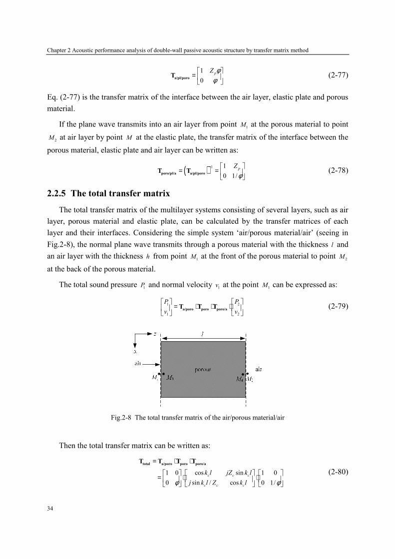
Chapter 2 Acoustic performance analysis of double-wall passive acoustic structure by transfer matrix method
34
1
0
pZ φφ
=
a/pl/poroT (2-77)
Eq. (2-77) is the transfer matrix of the interface between the air layer, elastic plate and porous
material.
If the plane wave transmits into an air layer from point 1
M at the porous material to point
2M at air layer by point M at the elastic plate, the transfer matrix of the interface between the
porous material, elastic plate and air layer can be written as:
( ) 1 1
0 1/
pZ
φ−
= =
poro/pl/a a/pl/poroT T (2-78)
2.2.5 The total transfer matrix
The total transfer matrix of the multilayer systems consisting of several layers, such as air
layer, porous material and elastic plate, can be calculated by the transfer matrices of each
layer and their interfaces. Considering the simple system ‘air/porous material/air’ (seeing in
Fig.2-8), the normal plane wave transmits through a porous material with the thickness l and
an air layer with the thickness h from point 1
M at the front of the porous material to point 2
M
at the back of the porous material.
The total sound pressure 1
P and normal velocity 1
v at the point 1
M can be expressed as:
1 2
1 2
P P
v v
= ⋅ ⋅ ⋅
a/poro poro poro/aT T T (2-79)
Fig.2-8 The total transfer matrix of the air/porous material/air
Then the total transfer matrix can be written as:
cos sin1 0 1 0
sin / cos0 0 1/
c c c
c c c
k l jZ k l
j k l Z k lφ φ
= ⋅ ⋅
= ⋅ ⋅
total a/poro poro poro/aT T T T
(2-80)

Chapter 2 Acoustic performance analysis of double-wall passive acoustic structure by transfer matrix method
35
Considering the system ‘porous material/air/plate’ (seeing in Fig.2-9), the normal plane
wave transmits through the porous material (thickness l ), air gap (thickness e ), and an elastic
plate (thickness h , simply supported) from point 1
M at the front of the l to point 2
M at the
back of the elastic plate.
Fig.2-9 The total transfer matrix of the porous material/air/plate
The total transfer matrix between the point 1
M and the point 2
M can be expressed as:
= ⋅ ⋅ ⋅ ⋅total a/poro poro poro/a a a/pl/a
T T T T T T (2-81)
Considering the system ‘plate/porous material/plate’ (seeing in Fig.2-10), the normal
plane wave transmits through an elastic plate 1 (thickness 1
h , simply supported), a porous
material (thickness l ), and an elastic plate 2 (thickness 2
h , simply supported) from point 1
M
at the front of the elastic plate 1 to point 2
M at the back of the elastic plate 2.
Fig.2-10 The total transfer matrix of the plate/porous material/plate
The total transfer matrix between the point 1
M and the point 2
M can be expressed as:
= ⋅ ⋅total a/pl/poro poro poro/pl/a
T T T T (2-82)

Chapter 2 Acoustic performance analysis of double-wall passive acoustic structure by transfer matrix method
36
Considering the system ‘porous material/air/plate/air/porous material/air/plate’ (seeing in
Fig.2-11), the normal plane wave transmits through a porous material (thickness l ), an air
layer (thickness 1
e ), an elastic plate 1 (thickness 1
h , simply supported), an air layer (thickness
2e ), a porous material (thickness l ), an air layer (thickness
3e ), and an elastic plate 2
(thickness 2
h , simply supported) from point 1
M at the front of the porous material to point 2
M
at the back of the elastic plate 2.
Fig.2-11 The total transfer matrix of the porous material/air/plate/air/porous material/air/plate
The total transfer matrix between the point 1
M and the point 2
M can be expressed as:
= ⋅ ⋅ ⋅ ⋅ ⋅ ⋅ ⋅ ⋅ ⋅ ⋅total a/poro poro poro/a a pl a a/poro poro poro/a a pl
T T T T T T T T T T T T (2-83)
2.3 Numerical examples
In this section, some examples of double-wall acoustic absorbent or/and insulation
structures are modeled by the transfer matrix method, and their absorption coefficient and
transmission loss are calculated. The transfer matrices of the total structures are obtained
through the expressions in section 2.2. The elastic plates and the porous materials used in
these structures are simply supported.
2.3.1 Sound absorbent system
The structure shown in Fig.2-9 is actually the / 4λ resonance absorber, whose absorption
peak appears in the condition that the distance between the reflective surface and porous
material is equivalent to / 4λ or odd multiple of / 4λ . Table.2-1 gives the physical parameters
of the used materials, in which the parameters of the porous materials have been obtained
from the Ref. [162]. According to Eq. (2-81) derived in the previous section and the
relationship between the transfer matrix and the scattering matrix, the total scattering matrix
of this structure can be obtained, and its absorption coefficient and transmission loss can be
calculated.
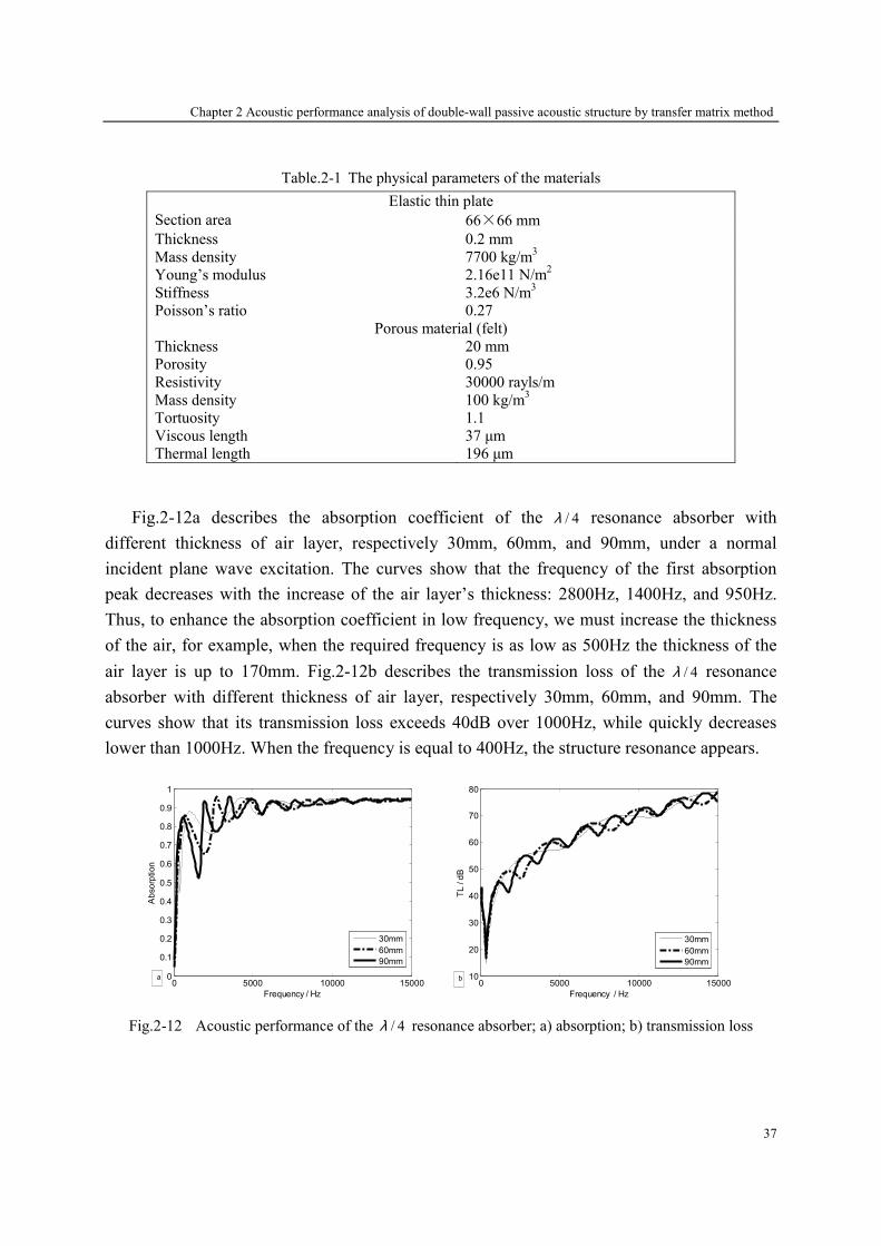
Chapter 2 Acoustic performance analysis of double-wall passive acoustic structure by transfer matrix method
37
Table.2-1 The physical parameters of the materials
Elastic thin plate
Section area 66×66 mm
Thickness 0.2 mm
Mass density 7700 kg/m3
Young’s modulus 2.16e11 N/m2
Stiffness 3.2e6 N/m3
Poisson’s ratio 0.27
Porous material (felt)
Thickness 20 mm
Porosity 0.95
Resistivity 30000 rayls/m
Mass density 100 kg/m3
Tortuosity 1.1
Viscous length 37 µm
Thermal length 196 µm
Fig.2-12a describes the absorption coefficient of the / 4λ resonance absorber with
different thickness of air layer, respectively 30mm, 60mm, and 90mm, under a normal
incident plane wave excitation. The curves show that the frequency of the first absorption
peak decreases with the increase of the air layer’s thickness: 2800Hz, 1400Hz, and 950Hz.
Thus, to enhance the absorption coefficient in low frequency, we must increase the thickness
of the air, for example, when the required frequency is as low as 500Hz the thickness of the
air layer is up to 170mm. Fig.2-12b describes the transmission loss of the / 4λ resonance
absorber with different thickness of air layer, respectively 30mm, 60mm, and 90mm. The
curves show that its transmission loss exceeds 40dB over 1000Hz, while quickly decreases
lower than 1000Hz. When the frequency is equal to 400Hz, the structure resonance appears.
0 5000 10000 150000
0.1
0.2
0.3
0.4
0.5
0.6
0.7
0.8
0.9
1
Frequency / Hz
Absorption
30mm
60mm
90mm
a0 5000 10000 15000
10
20
30
40
50
60
70
80
Frequency / Hz
TL / dB
30mm
60mm
90mm
b
Fig.2-12 Acoustic performance of the / 4λ resonance absorber; a) absorption; b) transmission loss

Chapter 2 Acoustic performance analysis of double-wall passive acoustic structure by transfer matrix method
38
Fig.2-13 shows the loss power of the / 4λ resonance absorber with different thickness of
air layer. The curves show that there is energy dissipation in the / 4λ resonance absorber, and
it is increased with the frequency. for the existence of energy loss, and an upward trend with
increasing frequency. In the peak of the absorption coefficient, the loss power is up to
maximum, which means the radiating power achieves minimum and the more energy is
dissipated by the structure itself.
0 5000 10000 150000
5
10
15
Frequency / Hz
Wloss / dB
30mm
60mm
90mm
Fig.2-13 Loss power of the / 4λ resonance absorber
2.3.2 Sound insulation system
A typical double-wall sound insulation structure is shown in Fig.2-10, in which the core
can be an air gap, a porous material or their combination. The physical parameters of the used
materials are given in Table.2-1, and the thickness of the air gap is 20mm. Fig.2-14 describes
the absorption coefficient and transmission loss of three kinds of the double-wall sound
insulation structures: plate-air-plate, plate-porous-plate, and plate-air-porous-air-plate. The
curves show that the absorption coefficient of these sound insulation systems is very weak,
but their transmission loss is perfect in whole frequency band except in the resonance
frequencies. Besides, in the condition of the same elastic plate used, the first resonance
frequency of the double-wall structure will not be changed with different cores, 230Hz, which
is also the resonance frequency of the elastic plate. However, the second resonance frequency
changes with the core: 530Hz, 480Hz, and 350Hz, which are the resonance frequencies of the
total structures.
Moreover, it has been concluded that the system with a porous material core can improve
the transmission performance in first resonance frequency obviously, comparing to the one
with an air gap core, due to the porous media dissipates the wave energy by producing friction
in pore and radiating heat. Besides, because of the acoustical wave attenuation in air, the
system with several layers of air gap and porous medium can insulate more sound
transmission in whole frequencies.
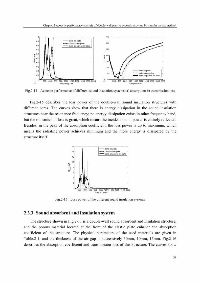
Chapter 2 Acoustic performance analysis of double-wall passive acoustic structure by transfer matrix method
39
200 400 600 800 1000 1200 1400 1600 1800 20000
0.1
0.2
0.3
0.4
0.5
0.6
0.7
0.8
0.9
1
Frequency / Hz
Absorption
plate-air-plate
plate-porous-plate
plate-air-porous-air-plate
a 200 400 600 800 1000 1200 1400 1600 1800 20000
10
20
30
40
50
60
70
Frequency / Hz
TL / dB
plate-air-plate
plate-porous-plate
plate-air-porous-air-plate
b
Fig.2-14 Acoustic performance of different sound insulation systems; a) absorption; b) transmission loss
Fig.2-15 describes the loss power of the double-wall sound insulation structures with
different cores. The curves show that there is energy dissipation in the sound insulation
structures near the resonance frequency; no energy dissipation exists in other frequency band,
but the transmission loss is great, which means the incident sound power is entirely reflected.
Besides, in the peak of the absorption coefficient, the loss power is up to maximum, which
means the radiating power achieves minimum and the more energy is dissipated by the
structure itself.
200 400 600 800 1000 1200 1400 1600 1800 20000
2
4
6
8
10
12
14
16
Frequency / Hz
Wloss / dB
plate-air-plate
plate-porous-plate
plate-air-porous-air-plate
Fig.2-15 Loss power of the different sound insulation systems
2.3.3 Sound absorbent and insulation system
The structure shown in Fig.2-11 is a double-wall sound absorbent and insulation structure,
and the porous material located at the front of the elastic plate enhance the absorption
coefficient of the structure. The physical parameters of the used materials are given in
Table.2-1, and the thickness of the air gap is successively 30mm, 10mm, 15mm. Fig.2-16
describes the absorption coefficient and transmission loss of this structure. The curves show
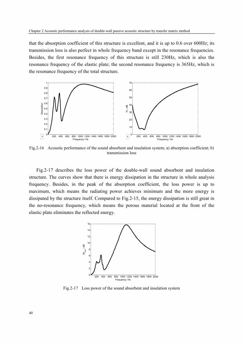
Chapter 2 Acoustic performance analysis of double-wall passive acoustic structure by transfer matrix method
40
that the absorption coefficient of this structure is excellent, and it is up to 0.6 over 600Hz; its
transmission loss is also perfect in whole frequency band except in the resonance frequencies.
Besides, the first resonance frequency of this structure is still 230Hz, which is also the
resonance frequency of the elastic plate; the second resonance frequency is 365Hz, which is
the resonance frequency of the total structure.
200 400 600 800 1000 1200 1400 1600 1800 20000
0.1
0.2
0.3
0.4
0.5
0.6
0.7
0.8
0.9
1
Frequency / Hz
Absorption
a 200 400 600 800 1000 1200 1400 1600 1800 20000
10
20
30
40
50
60
70
Frequency / Hz
TL / dB
b
Fig.2-16 Acoustic performance of the sound absorbent and insulation system; a) absorption coefficient; b)
transmission loss
Fig.2-17 describes the loss power of the double-wall sound absorbent and insulation
structure. The curves show that there is energy dissipation in the structure in whole analysis
frequency. Besides, in the peak of the absorption coefficient, the loss power is up to
maximum, which means the radiating power achieves minimum and the more energy is
dissipated by the structure itself. Compared to Fig.2-15, the energy dissipation is still great in
the no-resonance frequency, which means the porous material located at the front of the
elastic plate eliminates the reflected energy.
200 400 600 800 1000 1200 1400 1600 1800 20000
2
4
6
8
10
12
14
16
Frequency / Hz
Wloss / dB
Fig.2-17 Loss power of the sound absorbent and insulation system

Chapter 2 Acoustic performance analysis of double-wall passive acoustic structure by transfer matrix method
41
2.4 Conclusions
In this chapter, the transfer matrix method is applied to analyze the acoustic characteristic
of the double-wall passive acoustic structure. Firstly, the definition of the transfer matrix and
scattering matrix are given in the acoustic structure, and the relationship between them is also
expressed. Based on the sound propagation principle, the transfer matrix of the elastic simply
supported plate, the air gap, the rigid porous material and the interface between each layer are
modeled and then deduced to establish the total transfer matrix of the double-wall structure.
Lastly, the absorption coefficient and transmission loss of the double-wall passive acoustic
structure are calculated and analyzed with some numerical examples.


Chapter 3. Acoustic performance analysis of hybrid active acoustic structure by scattering matrix method
43
Chapter 3
Acoustic performance analysis of hybrid active
acoustic structure by scattering matrix method
In the preceding chapter, the acoustic performance of the double-wall passive structure is
analyzed by the transfer matrix method, and some examples of sound absorbent or/and
insulation systems are given. However, when the double-wall structures are hybrid (including
active control), the transfer matrix method is not suitable to model the problem since
calculations become complicate. Moreover, even if the structure is passive, the acoustic
characteristics of the structure can not be directly expressed by the transfer matrix. Therefore,
a concept of the scattering matrix [126] is proposed.
According to the definition of the scattering matrix, when the structure is excited only by
the incident wave from the left side, the elements 11
D and 21
D of the scattering matrix
respectively represent the reflection and transmission coefficients under the incident wave
excitation from the left side; when the structure is excited only by the incident wave from the
right side, the elements 22
D and 12
D of the scattering matrix respectively represent the
reflection and transmission coefficients under the incident wave excitation from the right side.
Thus, the acoustic characteristics of the structure can be directly expressed by the scattering
matrix.
For the passive structure, the scattering matrix can be directly derived by the transfer
matrix based on the principle of sound wave propagation; when the structure is with active
control, the unit having the secondary source should be analyzed separately. Similar to the
transfer matrix method, the scattering matrix of total hybrid active structure can also be

Chapter 3. Acoustic performance analysis of hybrid active acoustic structure by scattering matrix method
44
obtained by multiplying the scattering matrix of each layer due to the continuity nature of the
sound pressure and velocity.
This chapter aims at analyzing the acoustic characteristic of the hybrid active structure and
to developing a hybrid active acoustic structure having good performance on both absorption
and acoustic insulation for a wide frequency range. These hybrid active structures combine
passive and active means by using passive layers and active plate, respectively. Passive layers
include absorbent material (porous layer or/and micro-perforate plate) located in the emission
side to increase absorption. The active plate consisting of two piezoelectric patches bonded to
an elastic thin plate acts as a secondary source in order to improve acoustic insulation at low
and resonances frequencies. By analogy with duct systems, the active plate in hybrid active
acoustic structure is modeled as a two-port source. Using the scattering matrix method, it can
be completely described in form of a scattering matrix and a source strength vector which
represents respectively the passive and active proprieties of this plate. When systems or layers
are passive, such as porous layers, elastic thin plate etc, only the scattering matrix is sufficient
to characterize completely their acoustical behavior. Simulation of active control of hybrid
systems is carried out by introducing a source vector for the secondary source in order to
minimize the sound pressure level at the control point. The acoustic performance of hybrid
active structures, transmission loss and absorption, are then deduced from the secondary
source vector and the scattering matrices of all layers or elements composing the hybrid
system.
3.1 Theoretical basis and analytical simulation
3.1.1 The acoustical behavior of an active plate
The secondary source in the hybrid active structure is produced by gluing the piezoelectric
ceramics onto both sides of an elastic plate simply supported, and then imposing an opposite
voltage on the piezoelectric ceramics. The elastic plate with the piezoelectric ceramics can be
called the active plate shown in Fig.3-1. The secondary source generated by the active plate is
not directional, and it radiates sound waves not only to the left side of the structure but also to
the right side of the structure. Suppose that the primary source is located at the left side of the
structure, the sound wave radiated by the active plate which transmits to the left side of the
structure will interfere with the primary source and produce the ‘acoustic feedback’
phenomenon. Therefore, this phenomenon should be taken into account when modeling the
active plate.

Chapter 3. Acoustic performance analysis of hybrid active acoustic structure by scattering matrix method
45
Fig.3-1 The active plate
This active plate can be modeled as a two-port source in form of a radiated source vector
SP and a scattering matrix SD . The relationship between the incoming pressure wave vector
1 1 2 2( ) ( )T
P z P z+ − and the outgoing pressure wave vector 1 1 2 2( ) ( )
T
P z P z− + are written as:
11 1 1 1
22 2 2 2
( )( ) ( ),
( )( ) ( )
S
S
P zP z P z
P zP z P z
−− +
++ −
= ⋅ + =
S
S SD P P (3-1)
Here, S
P + and S
P − are the pressure radiated by the active plate in the right and the left side,
respectively. The scattering matrix SD describes the acoustical behavior of the active plate,
while S
P represents its active behavior. When this plate is acting as a secondary source of an
active control system, S
P depends of external acoustic conditions (incident pressures, external
discontinuities…).
3.1.2 The active sound absorbent structure
As described in Chapter 2, the λ/4 resonance absorber is an absorbent system in which the
porous material is placed at a distance equal to a quarter of a wavelength from the rigid wall,
in order that the pressure vanishes at the back face, i.e.2
0P = , shown in Fig.3-2(a). According
to Ref. [162], 2
0P = means the surface impedance s
Z (s
Z eσ= in Darcy’s law) of the porous
material matches the characteristic impedance of air, that is 0 0s
Z e cσ ρ= = , therefore the
maximum absorption coefficient is obtained under normal incidence. Herein, 0
ρ , 0
c are the
air density and velocity, σ , e are the resistivity and thickness of the porous material.
However, this passive absorber raises two major problems: (1) The required air gap for a low
frequency becomes very large (e.g., / 4 0.17mλ = in air at 500 Hz); (2) This system is only
effective in narrow frequency bands, especially for low frequencies.

Chapter 3. Acoustic performance analysis of hybrid active acoustic structure by scattering matrix method
46
Fig.3-2 The absorbent systems; (a) the λ/4 resonance absorber; (b) the active absorber
Hence, an active absorber appears to be particularly efficient in avoiding these drawbacks:
the air gap can be replaced by an active control loop which minimizes the pressure 2 2( )P z
(Fig.3-2(b)). The secondary source generates a pressure wave, which cancels the primary one
by destructive interference at the microphone location (point A), just behind the porous layer,
and then produces a pressure release condition at the back surface of the layer. Thus,
broadband excitations can be controlled with a reduced absorbent thickness. This active
absorber, called ‘an equivalent of the λ/4 resonance absorber’, also offers the advantage of
separating the control system from a hostile environment (air flow or hot stream for instance).
The scattering matrix 1D of the porous material layer located between axial
coordinates 1z and 2z leads to relationships between 1 1 2 2( ) ( )T
P z P z+ − and 1 1 2 2( ) ( )
T
P z P z− + :
1 1 1 1
2 2 2 2
( ) ( )
( ) ( )
P z P z
P z P z
− +
+ −
= ⋅
1D (3-2)
The scattering matrix 2D of the air gap layer located between 2z and 3z leads to the
following relations:
2 2 2 2
2 3 2 3
( ) ( )
( ) ( )
P z P z
P z P z
− +
+ −
= ⋅
2D (3-3)
In the case of anechoic upstream acoustic conditions ( )3 3( ) 0P z− = , the scattering matrix SD
of the active plate located between 3z and 4z gives the following equations systems:
2 3 32 3
3 4 4
( ) ( )( )
( ) ( )0
S
S
P z P zP z
P z P z
− −+
+ +
= ⋅ +
SD (3-4)

Chapter 3. Acoustic performance analysis of hybrid active acoustic structure by scattering matrix method
47
To simulate the active control of the error sensor position at 2z , the pressure3
( )S
P z−
radiated by the active plate in the left side must be introduced in computations in order to
minimize the acoustic pressure2 2( )P z . This is possible only if the value of the pressure
4( )
SP z+
radiated in the right side is known or related with 3
( )S
P z− by a given relationship. However,
the used active plate has symmetrical geometry and symmetrical material proprieties. Hence,
radiated pressures S
P− and S
P+ are related by the following equation:
3 4( ) ( )S S S SP z P z and ϕ ϕ− + − += = − (3-5)
Here, S
ϕ − , S
ϕ + are respectively the phases of the radiating sound waves.
From Eq. (3-2) ~ (3-5), we can calculate2 2( )P z as well as the reflected and transmitted
pressures 1 1
( )P z− and 3 4
( )P z+ at the emission and the transmission side respectively:
2 2 1 1 1 2 4( ) ( ) ( )SP z a P z a P z+ += + (3-6)
1 1 3 1 1 4 4( ) ( ) ( )SP z a P z a P z− + += + (3-7)
3 4 5 1 1 6 4( ) ( ) ( )SP z a P z a P z+ + += + (3-8)
Here,
2
211 2
22 111S
DA
D D=
−
2
221 2
22 111S
DB
D D=
−
2 11 1
SA D A= 2 11 1
1SB D B= +
2 2
3 11 12 2A D D A= + 2
3 12 2B D B=
1
214 1
22 31
DA
D A=
−
1
22 3
4 1
22 31
D BB
D A=
−
5 3 4A A A=
5 3 4 3B A B B= +
1 4 5a A A= +
2 4 5a B B= + 1 1
3 11 12 5a D D A= +
1
4 12 5a D B=
5 21 1 4
Sa D A A= 6 21 1 4 21 1
1S Sa D A B D B= + +
1
ijD , 2
ijD , S
ijD , , 1, 2i j = , are the elements of the scattering matrices 1D , 2D , SD . These
scattering matrices are deduced from analytical transfer matricesa/poro/a
T , a
T , and a/pl/a
T (Chapter
2) associated respectively to the porous material, the air gap and the active plate.
It must be noted that a/pl/a
T is the passive transfer matrix of the active plate
(when 0S SP P− += = ). In active control, the pressure 2
P vanishes, thus
1
2 2 3 1 1
2
( ) 0 ( ) ( )S
aP z P z P z
a
+ += ⇒ = − (3-9)
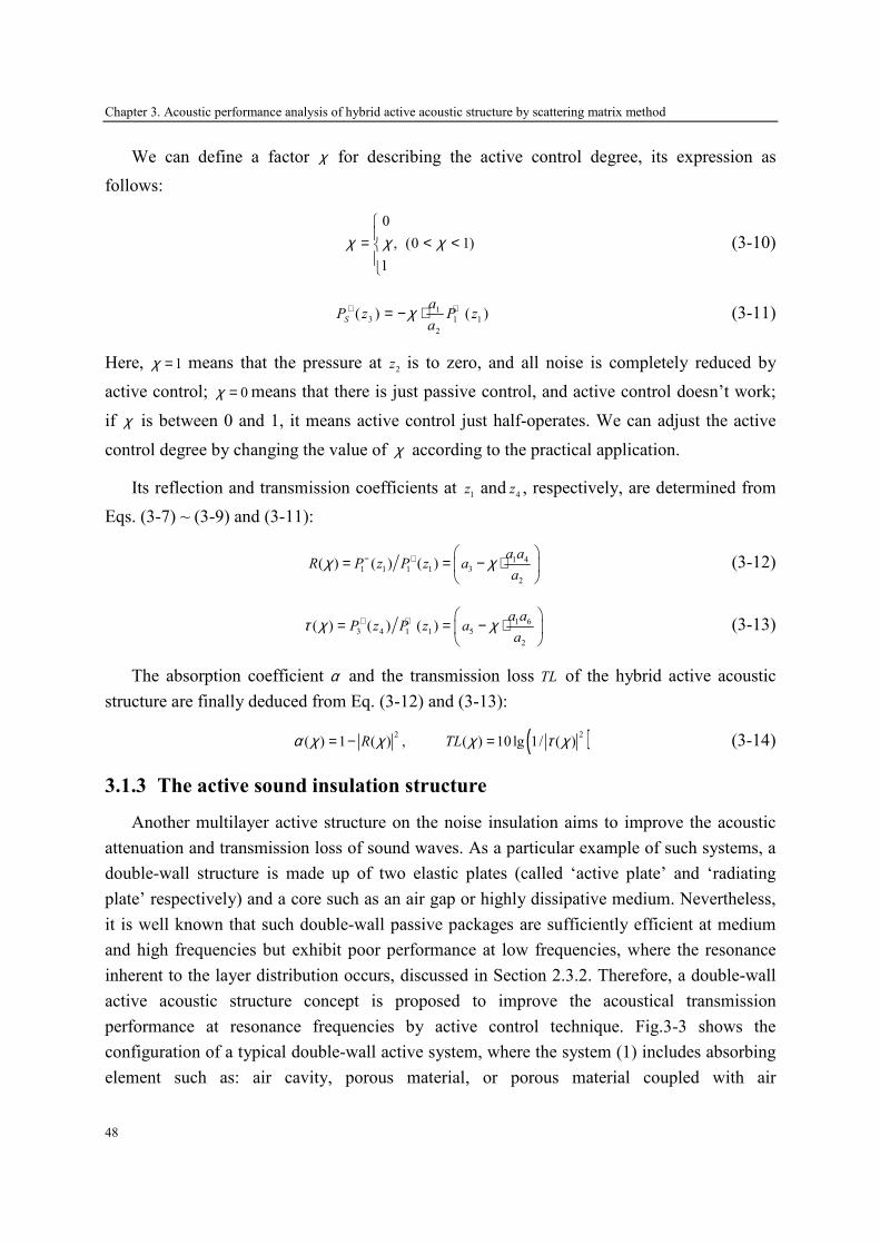
Chapter 3. Acoustic performance analysis of hybrid active acoustic structure by scattering matrix method
48
We can define a factor χ for describing the active control degree, its expression as
follows:
0
, (0 1)
1
χ χ χ= < <
(3-10)
1
3 1 1
2
( ) ( )S
aP z P z
aχ+ += − ⋅ (3-11)
Here, 1χ = means that the pressure at 2
z is to zero, and all noise is completely reduced by
active control; 0χ = means that there is just passive control, and active control doesn’t work;
if χ is between 0 and 1, it means active control just half-operates. We can adjust the active
control degree by changing the value of χ according to the practical application.
Its reflection and transmission coefficients at 1
z and4
z , respectively, are determined from
Eqs. (3-7) ~ (3-9) and (3-11):
1 41 1 1 1 3
2
( ) ( ) ( )a a
R P z P z aa
χ χ− + = = − ⋅
(3-12)
1 6
3 4 1 1 5
2
( ) ( ) ( )a a
P z P z aa
τ χ χ+ + = = − ⋅
(3-13)
The absorption coefficient α and the transmission loss TL of the hybrid active acoustic
structure are finally deduced from Eq. (3-12) and (3-13):
( )2 2 ( ) 1 ( ) , ( ) 10 lg 1/ ( )R TLα χ χ χ τ χ= − = (3-14)
3.1.3 The active sound insulation structure
Another multilayer active structure on the noise insulation aims to improve the acoustic
attenuation and transmission loss of sound waves. As a particular example of such systems, a
double-wall structure is made up of two elastic plates (called ‘active plate’ and ‘radiating
plate’ respectively) and a core such as an air gap or highly dissipative medium. Nevertheless,
it is well known that such double-wall passive packages are sufficiently efficient at medium
and high frequencies but exhibit poor performance at low frequencies, where the resonance
inherent to the layer distribution occurs, discussed in Section 2.3.2. Therefore, a double-wall
active acoustic structure concept is proposed to improve the acoustical transmission
performance at resonance frequencies by active control technique. Fig.3-3 shows the
configuration of a typical double-wall active system, where the system (1) includes absorbing
element such as: air cavity, porous material, or porous material coupled with air
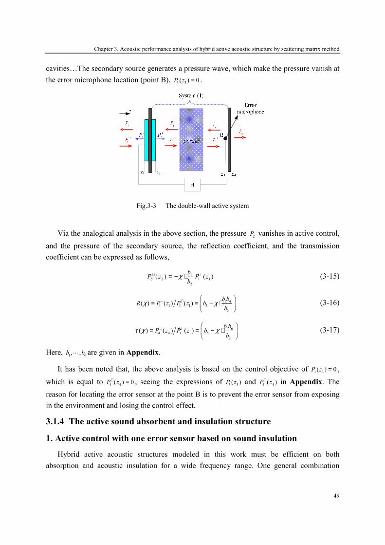
Chapter 3. Acoustic performance analysis of hybrid active acoustic structure by scattering matrix method
49
cavities…The secondary source generates a pressure wave, which make the pressure vanish at
the error microphone location (point B), 3 3( ) 0P z = .
Fig.3-3 The double-wall active system
Via the analogical analysis in the above section, the pressure 2
P vanishes in active control,
and the pressure of the secondary source, the reflection coefficient, and the transmission
coefficient can be expressed as follows,
1
2 1 1
2
( ) ( )S
bP z P z
bχ+ += − ⋅ (3-15)
1 41 1 1 1 3
2
( ) ( ) ( )b b
R P z P z bb
χ χ− + = = − ⋅
(3-16)
1 6
4 4 1 1 5
2
( ) ( ) ( )b b
P z P z bb
τ χ χ+ + = = − ⋅
(3-17)
Here, 1 6, ,b b⋯ are given in Appendix.
It has been noted that, the above analysis is based on the control objective of 3 3( ) 0P z = ,
which is equal to 4 4
( ) 0P z+ = , seeing the expressions of 3 3( )P z and
4 4( )P z+ in Appendix. The
reason for locating the error sensor at the point B is to prevent the error sensor from exposing
in the environment and losing the control effect.
3.1.4 The active sound absorbent and insulation structure
1. Active control with one error sensor based on sound insulation
Hybrid active acoustic structures modeled in this work must be efficient on both
absorption and acoustic insulation for a wide frequency range. One general combination

Chapter 3. Acoustic performance analysis of hybrid active acoustic structure by scattering matrix method
50
which reaches this goal is the system given in Fig.3-4, with one error sensor in active control.
This system consists of a system (1) located in the emission side in order to reduce reflection,
and an active cell in order to insure high acoustic insulation. The system (1) includes
absorbing elements such as: poroelastic layers coupled with air cavities, and/or a micro
perforate plate…The active cell consists of two plates coupled with the system (2) which can
be: an air or porous layer, or air/porous/air. The active plate vibrates in order to reduce the
pressure level at the error microphone located at 4z (point B), 4 4( ) 0P z = .
Fig.3-4 General configuration of the multilayer hybrid active acoustic structures
Similarly, the pressure 4
P vanishes in active control, and the pressure of the secondary
source, the reflection coefficient, and the transmission coefficient can be expressed as follows,
1
3 1 1
2
( ) ( )S
gP z P z
gχ+ += − ⋅ (3-18)
1 41 1 1 1 3
2
( ) ( ) ( )g g
R P z P z gg
χ χ− + = = − ⋅
(3-19)
1 6
5 5 1 1 5
2
( ) ( ) ( )g g
P z P z gg
τ χ χ+ + = = − ⋅
(3-20)
Here, 1 6, ,g g⋯ are given in Appendix.
2. Active control with one error sensors based on sound absorption
Another hybrid active acoustic structure with one error senor for improving sound
absorption performance with active control is shown in Fig.3-5, in which the error sensor
(point A) makes the system (1) as an equivalent of the λ/4 resonance absorber, 2 1( ) 0P z′ = .

Chapter 3. Acoustic performance analysis of hybrid active acoustic structure by scattering matrix method
51
1Z ′
Fig.3-5 The hybrid system in active control with two error sensor
Similarly, the pressure '
1P vanishes in active control, and the pressure of the secondary
source, the reflection coefficient, and the transmission coefficient can be expressed as follows,
1
3 1 1
2
( ) ( )S
eP z P z
eχ+ += − ⋅ (3-21)
1 6
1 1 1 1 5
2
( ) ( ) ( )e e
R P z P z ee
χ χ− + = = − ⋅
(3-22)
1 8
5 5 1 1 7
2
( ) ( ) ( )e e
P z P z ee
τ χ χ+ + = = − ⋅
(3-23)
Here, 1 6, ,e e⋯ are given in Appendix.
3. Active control with two error sensors
A hybrid active acoustic structure with two error sensors in active control is shown in
Fig.3-6, in which the combination of the active cells makes the system (1) as an equivalent of
the λ/4 resonance absorber and the system (2) as a sound insulation system. In this case, the
control objective is written as,
2 2 * *
2 1 4 4 2 1 2 1 4 4 4 4( ) ( ) ( ) ( ) ( ) ( )J P z P z P z P z P z P z′ ′ ′= + = + (3-24)
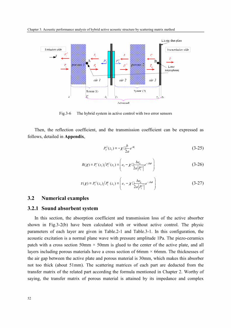
Chapter 3. Acoustic performance analysis of hybrid active acoustic structure by scattering matrix method
52
1Z ′
Fig.3-6 The hybrid system in active control with two error sensors
Then, the reflection coefficient, and the transmission coefficient can be expressed as
follows, detailed in Appendix,
3( )
2sj
S
bP z e
a
ϕχ+ = − ⋅ (3-25)
61 1 1 1 5
1
( ) ( ) ( )2
jbeR P z P z e e
a P
ϕχ χ− + − ∆+
= = − ⋅
(3-26)
85 5 1 1 7
1
( ) ( ) ( )2
jbeP z P z e e
a P
ϕτ χ χ+ + − ∆+
= = − ⋅
(3-27)
3.2 Numerical examples
3.2.1 Sound absorbent system
In this section, the absorption coefficient and transmission loss of the active absorber
shown in Fig.3-2(b) have been calculated with or without active control. The physic
parameters of each layer are given in Table.2-1 and Table.3-1. In this configuration, the
acoustic excitation is a normal plane wave with pressure amplitude 1Pa. The piezo-ceramics
patch with a cross section 50mm × 50mm is glued to the center of the active plate, and all
layers including porous materials have a cross section of 66mm × 66mm. The thicknesses of
the air gap between the active plate and porous material is 30mm, which makes this absorber
not too thick (about 51mm). The scattering matrices of each part are deducted from the
transfer matrix of the related part according the formula mentioned in Chapter 2. Worthy of
saying, the transfer matrix of porous material is attained by its impedance and complex

Chapter 3. Acoustic performance analysis of hybrid active acoustic structure by scattering matrix method
53
propagation constant calculated with effective density ( )e
ρ ω and bulk modulus ( )K ω ,
mentioned in Refs. [115] and [130].
Fig.3-7(a) shows the absorption coefficient α with 0, 0.2, 0.5, 0.8, 1χ = . The improvement of
α is significant after the deployment of active control. Comparison between active and
passive control shows a more efficient improvement of the absorption with active control in
the frequencies less than 500Hz. Besides, with different active control degree ( 0.2 1χ = ∼ ), the
absorption of the active absorber has been improved obviously less than 400Hz, which is the
resonance of the active plate. Fig.3-7(b) shows the transmission loss TL with
0, 0.2, 0.5, 0.8, 1χ = . Comparing the results of the active and passive control in Fig.3-7(b), the
transmission loss with active control has been decreased in all-range frequency (except for
0.2χ = in resonance frequency), and the more the control degree is, the lower the transmission
loss is, because the active plate is a two-port source which can produce a transmitting wave in
downstream side. Therefore, this active absorber is an efficient sound absorbent system,
where it is not noise insulation structure.
Table.3-1 Physic parameters of piezoelectric ceramic
Thickness 0.5 mm
Mass density 7760 kg/m3
Young’s modulus 9.6e10
Poisson’s ratio 0.34
200 400 600 800 1000 1200 1400 1600 1800 20000
0.1
0.2
0.3
0.4
0.5
0.6
0.7
0.8
0.9
1
Frequency / Hz
Absorption
χ = 0χ = 0.2χ = 0.5χ = 0.8χ = 1
a 200 400 600 800 1000 1200 1400 1600 1800 2000-10
0
10
20
30
40
50
60
Frequency / Hz
TL / dB
χ = 0χ = 0.2χ = 0.5χ = 0.8χ = 1
b
Fig.3-7 Acoustic performance of the active absorber with different control degree; a) absorption; b)
transmission loss
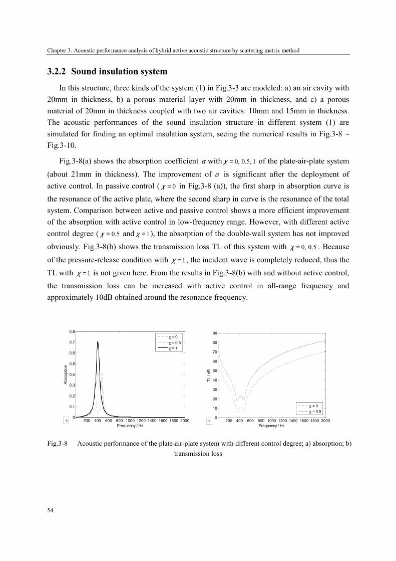
Chapter 3. Acoustic performance analysis of hybrid active acoustic structure by scattering matrix method
54
3.2.2 Sound insulation system
In this structure, three kinds of the system (1) in Fig.3-3 are modeled: a) an air cavity with
20mm in thickness, b) a porous material layer with 20mm in thickness, and c) a porous
material of 20mm in thickness coupled with two air cavities: 10mm and 15mm in thickness.
The acoustic performances of the sound insulation structure in different system (1) are
simulated for finding an optimal insulation system, seeing the numerical results in Fig.3-8 ~
Fig.3-10.
Fig.3-8(a) shows the absorption coefficient α with 0, 0.5, 1χ = of the plate-air-plate system
(about 21mm in thickness). The improvement of α is significant after the deployment of
active control. In passive control ( 0χ = in Fig.3-8 (a)), the first sharp in absorption curve is
the resonance of the active plate, where the second sharp in curve is the resonance of the total
system. Comparison between active and passive control shows a more efficient improvement
of the absorption with active control in low-frequency range. However, with different active
control degree ( 0.5χ = and 1χ = ), the absorption of the double-wall system has not improved
obviously. Fig.3-8(b) shows the transmission loss TL of this system with 0, 0.5χ = . Because
of the pressure-release condition with 1χ = , the incident wave is completely reduced, thus the
TL with 1χ = is not given here. From the results in Fig.3-8(b) with and without active control,
the transmission loss can be increased with active control in all-range frequency and
approximately 10dB obtained around the resonance frequency.
200 400 600 800 1000 1200 1400 1600 1800 20000
0.1
0.2
0.3
0.4
0.5
0.6
0.7
0.8
Frequency / Hz
Absorption
χ = 0χ = 0.5χ = 1
a
200 400 600 800 1000 1200 1400 1600 1800 2000
0
10
20
30
40
50
60
70
80
90
Frequency / Hz
TL / dB
χ = 0χ = 0.5
b
Fig.3-8 Acoustic performance of the plate-air-plate system with different control degree; a) absorption; b)
transmission loss

Chapter 3. Acoustic performance analysis of hybrid active acoustic structure by scattering matrix method
55
Fig.3-9(a) shows the absorption coefficient α with 0, 0.5, 1χ = of the plate-porous-plate
system (about 21mm in thickness). The improvement of α is significant after the deployment
of active control. Comparison between active and passive control shows a more efficient
improvement of the absorption with active control in low-frequency range. Fig.3-9(b) shows
the transmission loss TL of this system with 0, 0.5χ = . Similarly, because of the pressure-
release condition with 1χ = , the incident wave is completely reduced, thus the TL with 1χ = is
not given here. Comparing active and passive control in Fig.3-9(b), the transmission loss can
be increased with active control in all-range frequency and approximately 8dB obtained
around the resonance frequency.
200 400 600 800 1000 1200 1400 1600 1800 20000
0.1
0.2
0.3
0.4
0.5
0.6
0.7
0.8
0.9
Frequency / Hz
Absorption
χ = 0χ = 0.5χ = 1
a
200 400 600 800 1000 1200 1400 1600 1800 2000
10
20
30
40
50
60
70
80
Frequency / Hz
TL / dB
χ = 0χ = 0.5
b
Fig.3-9 Acoustic performance of the plate-porous-plate system with different control degree; a)
absorption; b) transmission loss
Fig.3-10(a) shows the absorption coefficient α with 0, 0.5, 1χ = of the plate-air-porous-air-
plate system (about 46mm in thickness). The improvement of α is significant after the
deployment of active control. Comparison between active and passive control shows a more
efficient improvement of the absorption with active control in low-frequency range. Fig.3-
10(b) shows the transmission loss TL of this system with 0, 0.5χ = . Similarly, because of the
pressure-release condition with 1χ = , the incident wave is completely reduced, thus the TL
with 1χ = is not given here. Comparing active and passive control in Fig.3-10(b), the
transmission loss can be increased with active control in all-range frequency and
approximately 15dB obtained around the resonance frequency.
From the numerical results and discussions in above section, it can be seen that these
double-wall systems have a good transmission performance, but lack in efficient absorption
characteristic. Besides, the simulation results show that the transmission loss can be enhanced
in whole analysis frequency; however, the active control only improves the transmission loss
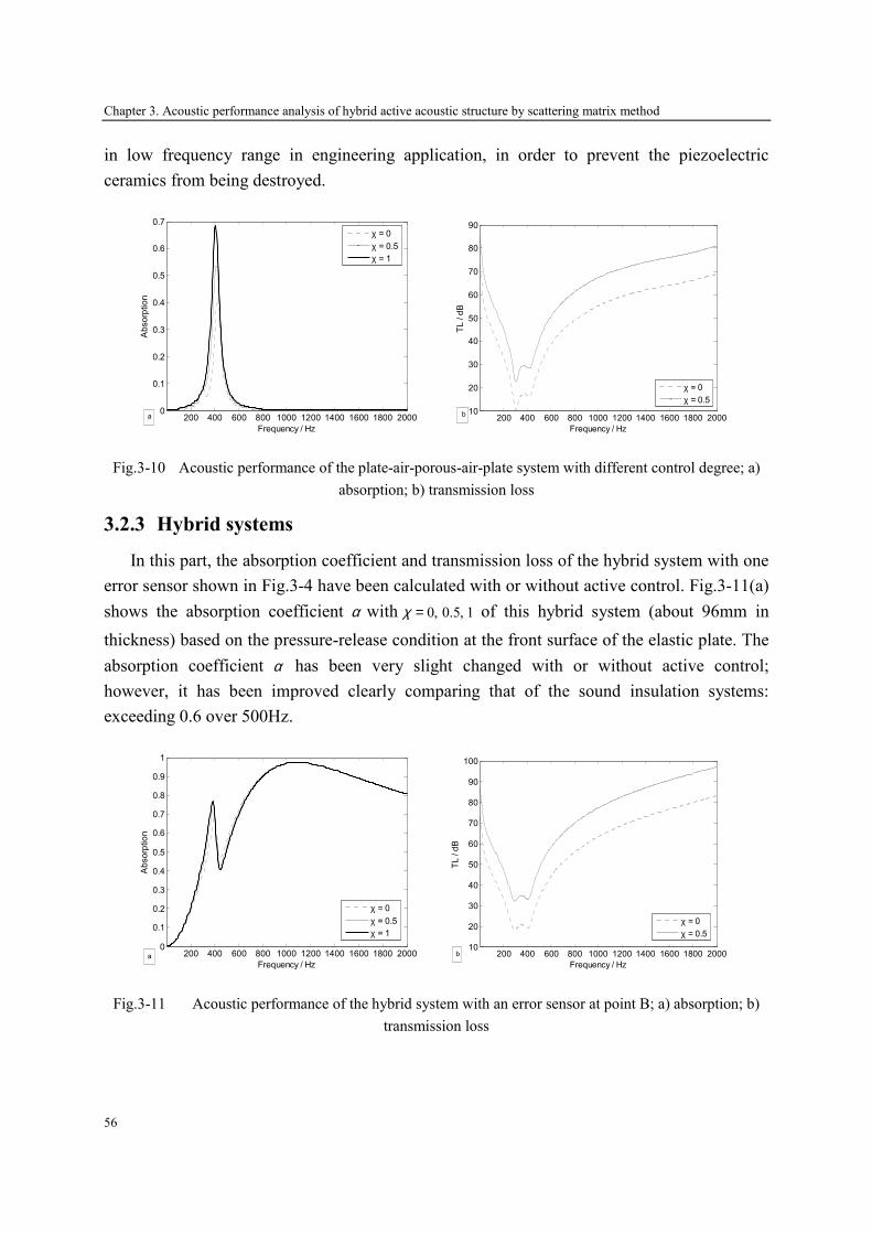
Chapter 3. Acoustic performance analysis of hybrid active acoustic structure by scattering matrix method
56
in low frequency range in engineering application, in order to prevent the piezoelectric
ceramics from being destroyed.
200 400 600 800 1000 1200 1400 1600 1800 20000
0.1
0.2
0.3
0.4
0.5
0.6
0.7
Frequency / Hz
Absorption
χ = 0χ = 0.5χ = 1
a
200 400 600 800 1000 1200 1400 1600 1800 2000
10
20
30
40
50
60
70
80
90
Frequency / Hz
TL / dB
χ = 0χ = 0.5
b
Fig.3-10 Acoustic performance of the plate-air-porous-air-plate system with different control degree; a)
absorption; b) transmission loss
3.2.3 Hybrid systems
In this part, the absorption coefficient and transmission loss of the hybrid system with one
error sensor shown in Fig.3-4 have been calculated with or without active control. Fig.3-11(a)
shows the absorption coefficient α with 0, 0.5, 1χ = of this hybrid system (about 96mm in
thickness) based on the pressure-release condition at the front surface of the elastic plate. The
absorption coefficient α has been very slight changed with or without active control;
however, it has been improved clearly comparing that of the sound insulation systems:
exceeding 0.6 over 500Hz.
200 400 600 800 1000 1200 1400 1600 1800 20000
0.1
0.2
0.3
0.4
0.5
0.6
0.7
0.8
0.9
1
Frequency / Hz
Absorption
χ = 0χ = 0.5χ = 1
a
200 400 600 800 1000 1200 1400 1600 1800 2000
10
20
30
40
50
60
70
80
90
100
Frequency / Hz
TL / dB
χ = 0χ = 0.5
b
Fig.3-11 Acoustic performance of the hybrid system with an error sensor at point B; a) absorption; b)
transmission loss
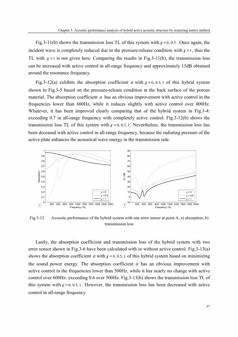
Chapter 3. Acoustic performance analysis of hybrid active acoustic structure by scattering matrix method
57
Fig.3-11(b) shows the transmission loss TL of this system with 0, 0.5χ = . Once again, the
incident wave is completely reduced due to the pressure-release condition with 1χ = , thus the
TL with 1χ = is not given here. Comparing the results in Fig.3-11(b), the transmission loss
can be increased with active control in all-range frequency and approximately 15dB obtained
around the resonance frequency.
Fig.3-12(a) exhibits the absorption coefficient α with 0, 0.5, 1χ = of this hybrid system
shown in Fig.3-5 based on the pressure-release condition at the back surface of the porous
material. The absorption coefficient α has an obvious improvement with active control in the
frequencies lower than 600Hz, while it reduces slightly with active control over 800Hz.
Whatever, it has been improved clearly comparing that of the hybrid system in Fig.3-4:
exceeding 0.7 in all-range frequency with completely active control. Fig.3-12(b) shows the
transmission loss TL of this system with 0, 0.5, 1χ = . Nevertheless, the transmission loss has
been deceased with active control in all-range frequency, because the radiating pressure of the
active plate enhances the acoustical wave energy in the transmission side.
200 400 600 800 1000 1200 1400 1600 1800 20000
0.1
0.2
0.3
0.4
0.5
0.6
0.7
0.8
0.9
1
Frequency / Hz
Absorption
χ = 0χ = 0.5χ = 1
a
200 400 600 800 1000 1200 1400 1600 1800 2000
-10
0
10
20
30
40
50
60
70
80
90
Frequency / Hz
TL / dB
χ = 0χ = 0.5χ = 1
b
Fig.3-12 Acoustic performance of the hybrid system with one error sensor at point A; a) absorption; b)
transmission loss
Lastly, the absorption coefficient and transmission loss of the hybrid system with two
error sensor shown in Fig.3-6 have been calculated with or without active control. Fig.3-13(a)
shows the absorption coefficient α with 0, 0.5, 1χ = of this hybrid system based on minimizing
the sound power energy. The absorption coefficient α has an obvious improvement with
active control in the frequencies lower than 500Hz, while it has nearly no change with active
control over 600Hz: exceeding 0.6 over 500Hz. Fig.3-13(b) shows the transmission loss TL of
this system with 0, 0.5, 1χ = . However, the transmission loss has been decreased with active
control in all-range frequency.
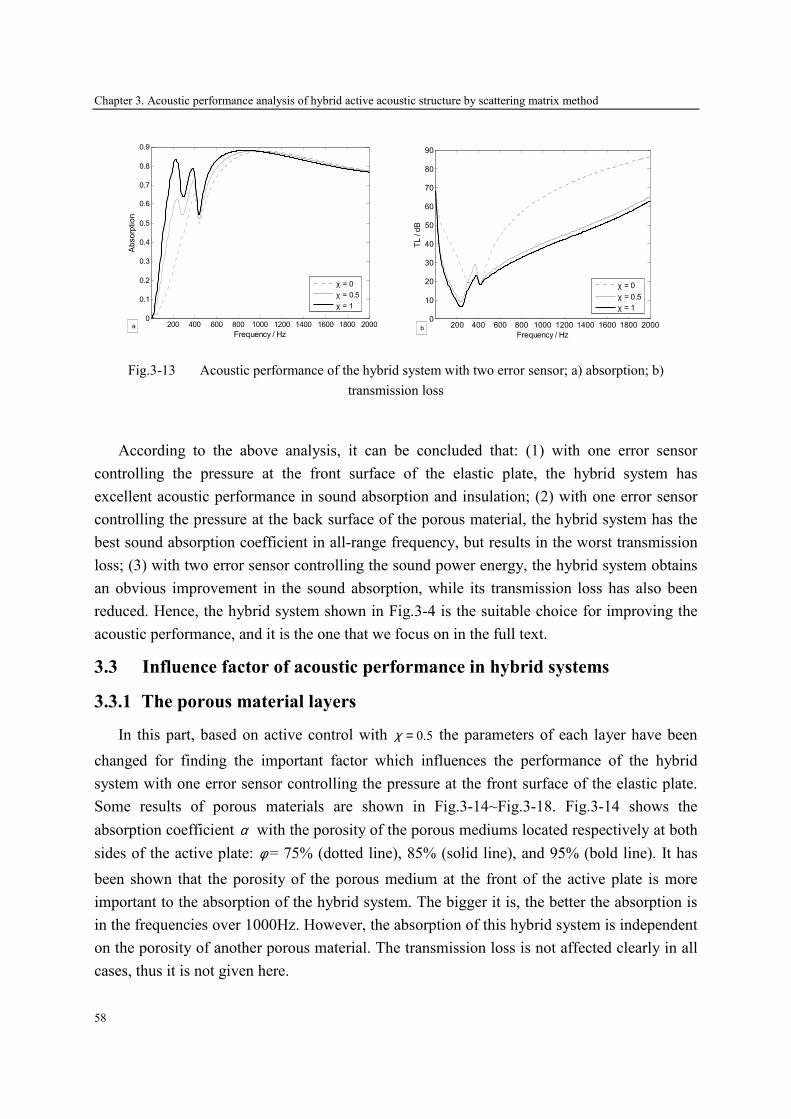
Chapter 3. Acoustic performance analysis of hybrid active acoustic structure by scattering matrix method
58
200 400 600 800 1000 1200 1400 1600 1800 20000
0.1
0.2
0.3
0.4
0.5
0.6
0.7
0.8
0.9
Frequency / Hz
Absorption
χ = 0χ = 0.5χ = 1
a
200 400 600 800 1000 1200 1400 1600 1800 2000
0
10
20
30
40
50
60
70
80
90
Frequency / Hz
TL / dB
χ = 0χ = 0.5χ = 1
b
Fig.3-13 Acoustic performance of the hybrid system with two error sensor; a) absorption; b)
transmission loss
According to the above analysis, it can be concluded that: (1) with one error sensor
controlling the pressure at the front surface of the elastic plate, the hybrid system has
excellent acoustic performance in sound absorption and insulation; (2) with one error sensor
controlling the pressure at the back surface of the porous material, the hybrid system has the
best sound absorption coefficient in all-range frequency, but results in the worst transmission
loss; (3) with two error sensor controlling the sound power energy, the hybrid system obtains
an obvious improvement in the sound absorption, while its transmission loss has also been
reduced. Hence, the hybrid system shown in Fig.3-4 is the suitable choice for improving the
acoustic performance, and it is the one that we focus on in the full text.
3.3 Influence factor of acoustic performance in hybrid systems
3.3.1 The porous material layers
In this part, based on active control with 0.5χ = the parameters of each layer have been
changed for finding the important factor which influences the performance of the hybrid
system with one error sensor controlling the pressure at the front surface of the elastic plate.
Some results of porous materials are shown in Fig.3-14~Fig.3-18. Fig.3-14 shows the
absorption coefficient α with the porosity of the porous mediums located respectively at both
sides of the active plate: φ = 75% (dotted line), 85% (solid line), and 95% (bold line). It has
been shown that the porosity of the porous medium at the front of the active plate is more
important to the absorption of the hybrid system. The bigger it is, the better the absorption is
in the frequencies over 1000Hz. However, the absorption of this hybrid system is independent
on the porosity of another porous material. The transmission loss is not affected clearly in all
cases, thus it is not given here.

Chapter 3. Acoustic performance analysis of hybrid active acoustic structure by scattering matrix method
59
200 400 600 800 1000 1200 1400 1600 1800 20000
0.1
0.2
0.3
0.4
0.5
0.6
0.7
0.8
0.9
1
Frequency / Hz
Absorption
φ = 75%φ = 85%φ = 95%
a 200 400 600 800 1000 1200 1400 1600 1800 20000
0.1
0.2
0.3
0.4
0.5
0.6
0.7
0.8
0.9
1
Frequency / Hz
Absorption
φ = 75%φ = 85%φ = 95%
b
Fig.3-14 Absorption coefficient of the hybrid system with different porous porosities; (a) α with the
different porosity of the porous material 1; (b) α with the different porosity of the porous material 2
Then the influence of the thickness of porous materials is given in Fig.3-15 and Fig.3-16.
Fig.3-15 shows the absorption coefficient and transmission loss of the hybrid system with
different thicknesses of the porous material 1 located at the front of the active plate: 10mm
(dotted line), 20mm (solid line), 40mm (bold line), and 14mm (dashed and bold line). To be
noted, when the thickness of the porous material 1 is equal to 14mm, the surface impedance
sZ of this porous material is equal to
0 0cρ . For this porous material, the bigger thickness has a
better transmission loss in all frequency ranges, but no improvement in very low frequencies.
However, the absorption of the hybrid system is affected obviously by the thickness of this
porous material. In lower than the resonance frequency, its absorption is improved by the
increased thickness, while it is decreased in some range over the resonance frequency.
200 400 600 800 1000 1200 1400 1600 1800 20000
0.1
0.2
0.3
0.4
0.5
0.6
0.7
0.8
0.9
1
Frequency / Hz
Absorption
10mm
20mm
40mm
14mm
a 200 400 600 800 1000 1200 1400 1600 1800 200020
30
40
50
60
70
80
90
100
Frequency / Hz
TL / dB
10mm
20mm
40mm
b
Fig.3-15 Acoustic performance of the hybrid system in different thicknesses of porous material 1; (a)
absorption coefficient; (b) transmission loss

Chapter 3. Acoustic performance analysis of hybrid active acoustic structure by scattering matrix method
60
Fig.3-16 shows the absorption coefficient and transmission loss of the hybrid system with
different thicknesses of the porous material 2 located at the back of the active plate: 10mm
(dotted line), 20mm (solid line) and 40mm (bold line). For this porous material, similarly, the
bigger thickness has a better transmission loss in all frequency ranges, but no improvement in
very low frequencies. Nevertheless, the absorption is not changed distinctly with the increased
thickness.
200 400 600 800 1000 1200 1400 1600 1800 20000
0.1
0.2
0.3
0.4
0.5
0.6
0.7
0.8
0.9
1
Frequency / Hz
Absorption
10mm
20mm
40mm
a 200 400 600 800 1000 1200 1400 1600 1800 200020
30
40
50
60
70
80
90
100
Frequency / Hz
TL / dB
10mm
20mm
40mm
b
Fig.3-16 Acoustic performance of the hybrid system in different thicknesses of porous material 2; (a)
absorption coefficient; (b) transmission loss
Lastly, the influence of the resistivity of porous materials is shown in Fig.3-17 and Fig.3-
18. Fig.3-17 shows the absorption coefficient and transmission loss of the hybrid system with
different resistivity of the porous materials located at the front of the active plate: 14750
(dotted line), 30000 (solid line) and 50000 (bold line). For this porous material, the higher
resistivity has a better transmission loss in all frequency ranges, but no improvement in very
low frequencies. However, the absorption of the hybrid system is affected obviously by the
resistivity of this porous material. In lower than the resonance frequency, its absorption is
improved by the increased resistivity, while it is decreased over the resonance frequency.
Fig.3-18 shows the absorption coefficient and transmission loss of the hybrid system with
different resistivity of the porous materials located at the back of the active plate: 14750
(dotted line), 30000 (solid line) and 50000 (bold line). For this porous material, similarly, the
bigger thickness has a better transmission loss in the frequency over 1000Hz, but no
improvement in low frequencies. Nevertheless, the absorption is not changed distinctly with
the increased resistivity. Therefore, it can be concluded that designing a hybrid system, more
attention should be paid to the porous material located at the front of the active plate and the
proper thickness, porosity and resistivity should be chosen for getting better acoustic
performance.
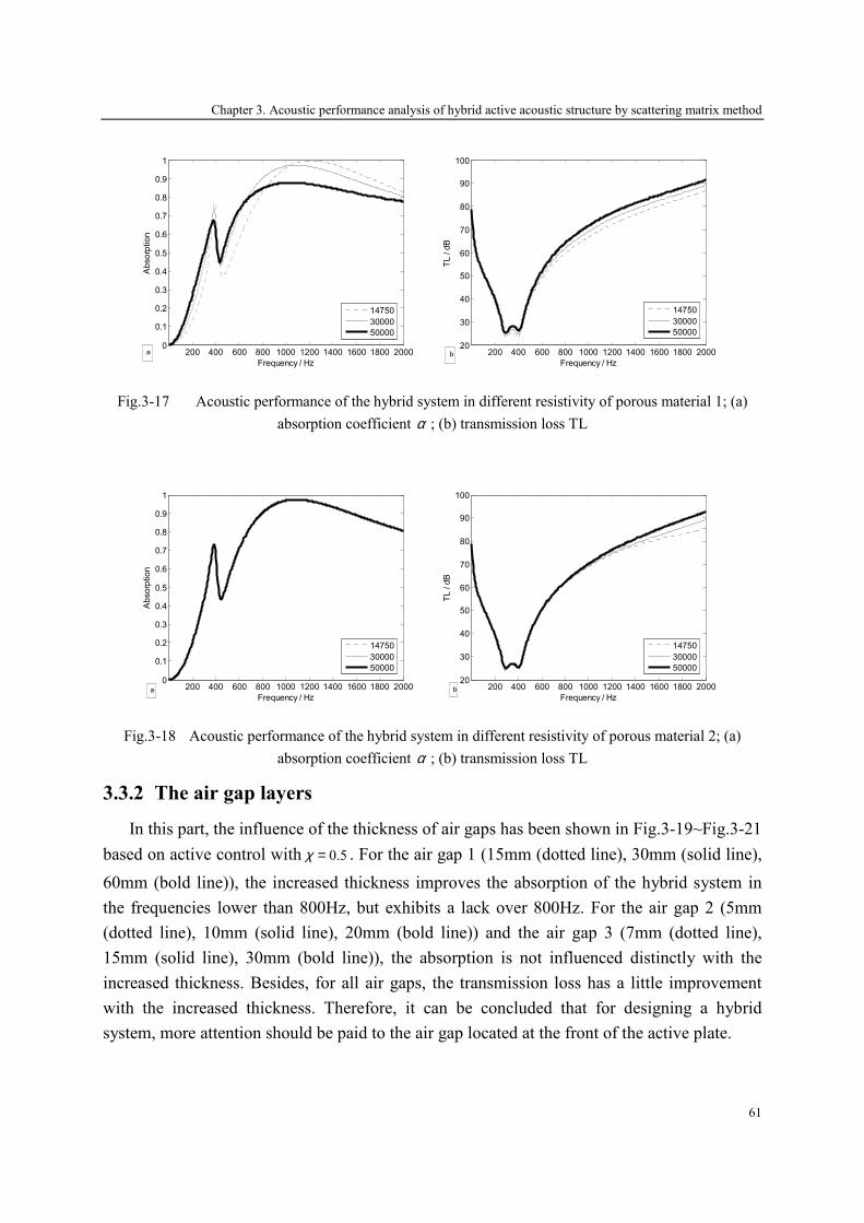
Chapter 3. Acoustic performance analysis of hybrid active acoustic structure by scattering matrix method
61
200 400 600 800 1000 1200 1400 1600 1800 20000
0.1
0.2
0.3
0.4
0.5
0.6
0.7
0.8
0.9
1
Frequency / Hz
Absorption
14750
30000
50000
a 200 400 600 800 1000 1200 1400 1600 1800 200020
30
40
50
60
70
80
90
100
Frequency / Hz
TL / dB
14750
30000
50000
b
Fig.3-17 Acoustic performance of the hybrid system in different resistivity of porous material 1; (a)
absorption coefficient α ; (b) transmission loss TL
200 400 600 800 1000 1200 1400 1600 1800 20000
0.1
0.2
0.3
0.4
0.5
0.6
0.7
0.8
0.9
1
Frequency / Hz
Absorption
14750
30000
50000
a 200 400 600 800 1000 1200 1400 1600 1800 200020
30
40
50
60
70
80
90
100
Frequency / Hz
TL / dB
14750
30000
50000
b
Fig.3-18 Acoustic performance of the hybrid system in different resistivity of porous material 2; (a)
absorption coefficient α ; (b) transmission loss TL
3.3.2 The air gap layers
In this part, the influence of the thickness of air gaps has been shown in Fig.3-19~Fig.3-21
based on active control with 0.5χ = . For the air gap 1 (15mm (dotted line), 30mm (solid line),
60mm (bold line)), the increased thickness improves the absorption of the hybrid system in
the frequencies lower than 800Hz, but exhibits a lack over 800Hz. For the air gap 2 (5mm
(dotted line), 10mm (solid line), 20mm (bold line)) and the air gap 3 (7mm (dotted line),
15mm (solid line), 30mm (bold line)), the absorption is not influenced distinctly with the
increased thickness. Besides, for all air gaps, the transmission loss has a little improvement
with the increased thickness. Therefore, it can be concluded that for designing a hybrid
system, more attention should be paid to the air gap located at the front of the active plate.
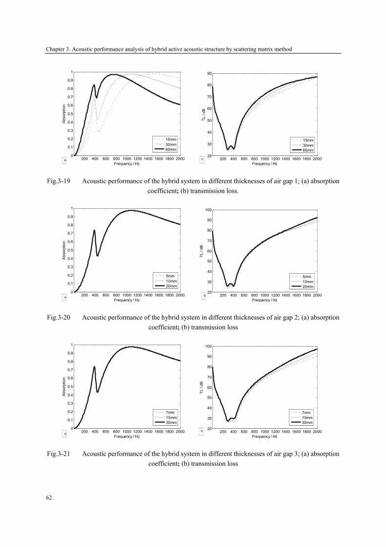
Chapter 3. Acoustic performance analysis of hybrid active acoustic structure by scattering matrix method
62
200 400 600 800 1000 1200 1400 1600 1800 20000
0.1
0.2
0.3
0.4
0.5
0.6
0.7
0.8
0.9
1
Frequency / Hz
Absorption
15mm
30mm
60mm
a
200 400 600 800 1000 1200 1400 1600 1800 2000
20
30
40
50
60
70
80
90
Frequency / Hz
TL / dB
15mm
30mm
60mm
b
Fig.3-19 Acoustic performance of the hybrid system in different thicknesses of air gap 1; (a) absorption
coefficient; (b) transmission loss.
200 400 600 800 1000 1200 1400 1600 1800 20000
0.1
0.2
0.3
0.4
0.5
0.6
0.7
0.8
0.9
1
Frequency / Hz
Absorption
5mm
10mm
20mm
a
200 400 600 800 1000 1200 1400 1600 1800 2000
20
30
40
50
60
70
80
90
100
Frequency / Hz
TL / dB
5mm
10mm
20mm
b
Fig.3-20 Acoustic performance of the hybrid system in different thicknesses of air gap 2; (a) absorption
coefficient; (b) transmission loss
200 400 600 800 1000 1200 1400 1600 1800 20000
0.1
0.2
0.3
0.4
0.5
0.6
0.7
0.8
0.9
1
Frequency / Hz
Absorption
7mm
15mm
30mm
a
200 400 600 800 1000 1200 1400 1600 1800 2000
20
30
40
50
60
70
80
90
100
Frequency / Hz
TL / dB
7mm
15mm
30mm
b
Fig.3-21 Acoustic performance of the hybrid system in different thicknesses of air gap 3; (a) absorption
coefficient; (b) transmission loss
Chapter 3. Acoustic performance analysis of hybrid active acoustic structure by scattering matrix method
63
3.4 Conclusions
In this chapter, a hybrid active acoustic structure allowing good acoustic insulation and
absorption for a wide frequency range have been modeled by the scattering matrix method.
These hybrid active acoustic structures combine passive and active means by using passive
layers and active plate, respectively. It is a combination of a sound absorbent system as ‘an
equivalent of the λ/4 resonance absorber’, and a sound insulation system for improving the
transmission loss. The secondary source is realized by an active plate consisting of two
piezoelectric patches bonded to an elastic thin plate in order to improve acoustic insulation at
low and resonances frequencies.
In the scattering matrix method, the active plate has been completely described in form of
a scattering matrix and a source strength vector which represents respectively the passive and
active proprieties of this plate. In active control, the source strength vector of the active plate
is calculated in order to minimize the sound pressure or power at the location of the error
sensor. The acoustic performances of the hybrid system, the absorption coefficient and
transmission loss, are then deduced from the secondary source vector and the scattering
matrix coefficients of all layers or elements composing this system. The simulation results
show that a significant gain on transmission loss (higher than 15 dB) has been obtained by
active control around the resonance frequency. Meanwhile, the absorption coefficient of this
hybrid system exceeds 0.6 over 500Hz.
Lastly, the influence factors which affect the acoustic performance of the hybrid system
have been investigated by simulation on different parameters of each layer. It can be
concluded that more attention should be paid to the layers located at the front of the active
plate when designing a hybrid system. The appropriate thickness, porosity and resistivity of
the porous material and the air gap’s thickness should be chosen for getting much better
acoustic performance of the hybrid system.
In conclusion, the scattering matrix approach is an efficient tool for modeling or
optimizing multilayered hybrid systems because of its simplicity. Indeed, when the elements
of hybrid systems cannot be modeled by analytical methods (ex: complex boundary
conditions, geometries…), numerical data in form of scattering-coefficients or radiated
pressures can easily be incorporated in the computation program. That allows a smaller
computation time compared with other numerical methods modeling the whole structure at
the same time. However, this approach is not a perfect method when the porous material is
elastic or coupled with an elastic plate. Due to the biphasic nature of the porous material, the
elasticity of the skeleton should be considered, and the strong coupling between the solid and

Chapter 3. Acoustic performance analysis of hybrid active acoustic structure by scattering matrix method
64
fluid phases cannot be ignored. Hence, a new method for modeling the poroelastic medium
should be proposed, described in the next chapter.
Chapter 4. Finite element study of hybrid active acoustic structure with poroelastic materials
65
Chapter 4
Finite element study of hybrid active acoustic
structure with poroelastic materials based on the (u,
p) formulation
In the preceding chapter, the acoustic performance of the hybrid active acoustic structure
is calculated by the scattering matrix method, in which the porous material is supposed as an
equivalent fluid with effective density and bulk modulus [129]. This type of modeling applies
to porous materials having a rigid skeleton, i.e., motionless or a very limp skeleton. In this
case, only one compression wave propagates in the air-saturated medium, and five important
parameters are needed to define the equivalent density and the equivalent impedance: porosity,
resistivity, tortuosity, viscous, and thermal length [129]. Hence, Helmholtz’s equation is a
governing equation in the porous material.
However, when the porous material is elastic (called ‘poroelastic’), or it is attached to an
elastic plate, this hypothesis is no more suitable. In this case, the porous material is subject to
three basic waves propagating simultaneously in the solid and fluid phase: two compressions
and one shearing waves. Therefore, the elasticity of the skeleton should be considered, and
the strong coupling between the solid and fluid phases cannot be ignored. Biot’s theory of
fluid saturated media is widely applied to describe the waves propagating in geophysics
materials and to establish its mechanical behavior. For several decades, many authors have
extended this theory to sound-absorbing materials, such as glass wool and polymer foams.
Based on their progresses, a (u, p) formulation described by the displacement in the solid
phase and the pressure in the fluid phase is developed with Biot’s theory to model the acoustic
behavior of the poroelastic material. This (u, p) formulation makes the scattering matrix
Chapter 4. Finite element study of hybrid active acoustic structure with poroelastic materials
66
method complicate and inconvenient for modeling the hybrid active acoustic structure with
poroelastic medium. Hence, a new method for modeling this hybrid system should be
proposed.
This chapter aims to develop a finite element model of hybrid active acoustic structure
with the (u, p) formulation in the Comsol environment. The partial differential equation of
porous materials is described with the Comsol formulation, and the couplings between each
layer are formulated in the Comsol environment. This model is validated by describing the
normal surface impedance for the analytically solved case of a one-dimensional porous
material with three boundary conditions: bonded into a rigid wall, attached with a layer of air,
and an active control condition with zero pressure in the rear of the porous medium. Besides,
the dynamic responses of some hybrid active acoustic structure are studied, in which
piezoelectric patches are added onto the excited plate behaving as a secondary vibrational
source, thus enhancing the effectiveness at low and/or resonance frequencies. The properties
of different layers in these hybrid systems are calculated in the Comsol environment and the
acoustic performance of the hybrid systems is validated by the numerical results of the
scattering matrix method.
4.1 The Biot’s theory of sound propagation in poroelastic material
4.1.1 The (u, p) formulation for poroelastic medium
Suppose the poroelastic material behaves like a visco-thermal equivalent fluid and has a
rigid frame, good precision can be obtained when incident wave is in high frequency, but it is
not appropriate in much low frequency because of the strong coupling between elastic solid
and fluid. A classical displacement-displacement formulation ( , )u U is proposed by Biot [131],
seeing Eq. (4-1).
11 12
22 12
( )
( )
b
b
ρ ρρ ρ
∇ ⋅ = + + −
∇ ⋅ = + − −
s s f s f
f f s s f
σ u U u U
σ U u u U
ɶɺɺ ɺɺɺ ɺ
ɶɺɺ ɺɺɺ ɺ (4-1)
Here, su and fU stand for the frame and fluid displacements respectively; sσ and fσ stand for
the frame and fluid stress tensor respectively. fσ depends on the pressure of fluid, and
pφ= − ⋅fσ I . 11
ρ and 22
ρ represent the relative densities of the frame and fluid, whereas 12
ρ
stands for a strong inertial coupling between the frame and fluid.
1/ 22
2 0
2 2 2
41
jb
α ηρ ωσφσ φ
∞ = + Λ
ɶ is
viscous damping coefficient depending on frequency. I is a unit diagonal matrix. The
relations between 11
ρ ,22
ρ ,12
ρ as follows:
11 12sρ ρ ρ= −
Chapter 4. Finite element study of hybrid active acoustic structure with poroelastic materials
67
22 0 12ρ φρ ρ= −
12 0( 1)ρ φρ α∞= − −
Here,s
ρ is the material density of poroelastic medium, and 0
ρ is air density.
Suppose this porous material is uniformity, and incident wave is a time-harmonic plane
wave, Eq. (4-1) can be rewritten by eliminating the factor j te ω :
2 2
11 120ω ρ ω ρ+ + ∇ ⋅ =s f su U σɶ ɶ (4-2)
2 2
22 120pω ρ ω ρ φ+ − ∇ =f sU uɶ ɶ (4-3)
Here
11 11/b jρ ρ ω= + ɶɶ
22 22/b jρ ρ ω= + ɶɶ
12 12/b jρ ρ ω= − ɶɶ
From Eq. (4-3), fU can be described by su :
12
2
2222
pρφρω ρ
= ∇ −f sU u
ɶ
ɶɶ (4-4)
A. Solid phase motion equation in ( , )u p formulation
Substituting Eq. (4-4) to (4-2)
2 12
22
0pρω ρ φρ
+ ∇ + ∇ ⋅ =s su σ
ɶɶ
ɶ (4-5)
Here ( )2
1211
22
ρρ ρ ρ= −ɶ
ɶ ɶɶ .
It is to be noted that ( , )=s s s fσ σ u U still depends on the fluid displacement fU , therefore a
mathematic operation is carried out according to the stress-strain relation [130] based on Biot
theory:
( , ) 2A N Q= ∇ ⋅ + + ∇ ⋅s s f s s fσ u U u ε U (4-6)
p R Qφ− ⋅ = ∇ ⋅ + ∇ ⋅f sI U u (4-7)
Here
2(1 ) 2
3b f
A K K Nφ
φ−= + −
Chapter 4. Finite element study of hybrid active acoustic structure with poroelastic materials
68
(1 )f
Q Kφ= −
fR Kφ=
N is the shear modulus of poroelastic medium; b
K and f
K are the bulk modulus of the solid
phase in vacuum and the fluid phase with the solid phase in motionless, 2 ( 1)
3(1 2 )b
NK
µµ+=
−,
( )f
K K ω= ; µ is Poisson ratio of solid phase.
Substituting Eq. (4-7) to (4-6):
2
( , ) 2Q Q
A N pR R
φ = − ∇ ⋅ + − ⋅
s s f s sσ u U u ε I (4-8)
Define
2
ˆ ( ) 2
22
3b
QA N
R
K N N
= − ∇ ⋅ +
= − ∇ ⋅ +
s s s s
s s
σ u u ε
u ε
(4-9)
Then
ˆ( , ) ( )Q
pR
φ= − ⋅s s f s sσ u U σ u I (4-10)
Substituting Eq. (4-10) to (4-5):
2ˆ ( ) 0pω ρ γ∇ ⋅ + + ∇ =s s sσ u uɶ ɶ (4-11)
Here, 12
22
Q
R
ργ φρ
= −
ɶɶ
ɶ. Equation (4-11) is the solid motion equation in ( , )u p formulation.
B. Fluid phase motion equation in ( , )u p formulation
Taking a divergence to Eq. (4-4):
2 12
2
2222
pρφρω ρ
∇ ⋅ = ∇ − ∇ ⋅f sU u
ɶ
ɶɶ (4-12)
Substituting Eq. (4-12) to Eq. (4-7):
2 2 222 22
20p p
R
ρ ρ γω ωφ
∇ + − ∇ ⋅ =su
ɶ ɶ ɶ (4-13)
Equation (4-13) is the fluid motion equation in ( , )u p formulation.

Chapter 4. Finite element study of hybrid active acoustic structure with poroelastic materials
69
Equation (4-11) and (4-13) are the ( , )u p formulation for poroelastic medium. The two
terms in Eq. (4-11) mean the solid vibration characteristic in vacuum, whereas the two terms
in Eq. (4-13) mean the acoustic wave propagation in fluid with motionless solid. The third
term in the two equations is the coupling correction between the solid and fluid phase.
4.1.2 Coupling boundary conditions
The couplings between poroelastic/air, poroelastic/elastic and poroelastic /poroelastic are
presented in this part. Simpler boundary conditions (a rigid wall, imposed pressure, imposed
displacements) can be directly derived from these formulations described below.
A. Poroelastic/air coupling
In the case of a poroelastic medium linked to an acoustic medium, Eq. (4-14) states the
continuity of the total normal stress, acoustic pressure and fluid flow [142].
2
0
1(1 )
a
a
a
p
p p
pφ φρ ω
⋅ = − ⋅=
− ⋅ + ⋅ = ∇ ⋅
t
s f
σ n n
u n U n n
(4-14)
Here ap is the pressure in the acoustic medium, tσ is the total stress tensor in the
poroelastic material, and n is the outward normal unit vector.
( , ) ( , ) ( , )
ˆ ( ) 1
su
Qp
Rφ
= = +
= − +
t t s f s s f f f
s s
σ σ u U σ u U σ U
σ u (4-15)
Substituting Eq. (4-15) to (4-14):
ˆ 1 1
0
0
a
a
a
Qp
R
p p
p p
φ ⋅ = − − + ⋅
∇ ⋅ = ∇ ⋅ =− =
s sσ (u ) n n
n n (4-16)
By substituting p for fU using Eq. (4-4), the correct normal acceleration can be obtained,
as written in Eq. (4-17).
22 12
0 22 22
11 1
ap p
ρ φω φρ ρ ρ
∇ ⋅ = ⋅ − + + ∇ ⋅
sn u n n
ɶ
ɶ ɶ (4-17)
B. Poroelastic/elastic coupling

Chapter 4. Finite element study of hybrid active acoustic structure with poroelastic materials
70
Suppose the poroelastic material is bonded onto an elastic solid, which encompasses total
continuity between the solid phase and elastic displacements, the continuity of the total
normal stress, displacement and no fluid flow at the interface are conserved as follows [142]:
⋅ ⋅
⋅ ⋅
t e
s e
f s
σ n = σ n
u = u
U n - u n = 0
(4-18)
Here eσ is the total stress tensor in the poroelastic material
Equation (4-18) can be rewritten as follows according to Eq. (4-4) and (4-15):
( )2
12 22
ˆ 1
0
Qp
R
p
φ
ω ρ ρφ
⋅ = + ⋅ + ⋅
∇ ⋅ = + ⋅
− =
s s e
s
e s
σ (u ) n n σ n
n u n
u u
ɶ ɶ (4-19)
C. Poroelastic/poroelastic coupling
In the case of a poroelastic medium linked to another poroelastic medium, the continuity
of the total normal stress, displacement of solid and fluid phase, and fluid flow can be
described by Eq. (4-20).
( ) ( )1 2
1 2
s sp p
φ φ
⋅ = ⋅==
⋅ − ⋅ = ⋅ − ⋅
t t
1 2
s s
1 2
f s f s
1 1 2 2
σ n σ n
u u
U n u n U n u n
(4-20)
Substituting Eq. (4-4) and (4-15) into (4-20), for poroelastic medium 1:
1 2
1 2 1
1 2
2 (1) (1) (2) (2)
2 22 12 12 12 12
1 22 2 2
1 1 2
ˆ ˆ( ) ( ) 1 1Q Q
pR R
p p
φ φ
φ ρ ρ ρ ρω ωφ φ φ
⋅ = ⋅ + + − + ⋅
+ +∇ ⋅ = ∇ ⋅ + − ⋅
s s s s
1 1 2 2
s
1
σ u n σ u n n
n n u nɶ ɶ ɶ ɶ
(4-21)
For poroelastic medium 2:
2 1
2 1 2
2 1
2 (2) (2) (1) (1)
2 21 12 12 12 12
2 12 2 2
2 2 1
ˆ ˆ( ) ( ) 1 1Q Q
pR R
p p
φ φ
φ ρ ρ ρ ρω ωφ φ φ
⋅ = ⋅ + + − + ⋅
+ +∇ ⋅ = ∇ ⋅ + − ⋅
s s s s
2 2 1 1
s
2
σ u n σ u n n
n n u nɶ ɶ ɶ ɶ
(4-22)

Chapter 4. Finite element study of hybrid active acoustic structure with poroelastic materials
71
4.2 Finite element method for modeling hybrid active structure
4.2.1 Passive process
A finite element method is used to analyze the acoustic wave propagation in hybrid active
acoustic structure based on Comsol environment. Comsol provides powerful applications
modes for acoustic, piezoelectric and elastic problems, but it does not currently provide a
specific application mode for poroelastic medium. Since the coupling between the fluid and
the solid phases occurs in poroelastic medium, the partial differential equations (PDE mode)
provided by Comsol is chosen for modeling the poroelastic material [147]. The partial
differential equation is rewritten here in Eq. (4-23).
0
T
l
⋅∇ =
∂ − ⋅ = + ∂
=
Γ F
LΓ n G
U
L
(4-23)
U is the vector of unknowns and Γ , F , G , L are PDE coefficients depending on U or its
differentiation, L is the ‘Dirichlet’ vector, and G is the ‘Neumann’ vector; l denotes the
Lagrange multiplier; n is the outward normal unit vector.
In cartesian coordinate system, the displacement of solid phase is presented by ( ), ,u v w=su ,
whereas the pressure of fluid phase is described by p. Compared the first term to Eq. (4-11)
and (4-13), Γ and F can be written as follows:
4
ˆ ( )ij
j p
Γ = = Γ ∇
s sσ uΓ (4-24)
2
2 222 224 2
i
pF
F pR
ω ρ γρ ρ γω ω
φ
− − ∇ = = − + ∇ ⋅
s
s
u
Fu
ɶ ɶ
ɶ ɶ ɶ (4-25)
According to the formulation of ˆ ( )s sσ u , and defining ,
s
k k
u v wu
x y z
∂ ∂ ∂= ∇ ⋅ = + +∂ ∂ ∂
su
x y zu v w= + + ,
Γ and F can be rewritten in details:
,
,
,
ˆ2 ( ) ( )
ˆ( ) 2 ( )
ˆ( ) ( ) 2
s
x k k y x z x
s
y x y k k y z
s
z x z y z k k
x y z
Nu Au N u v N u w
N u v Nv Au N w v
N u w N v w Nw Au
p p p
+ + +
+ + + =
+ + +
Γ (4-26)
Chapter 4. Finite element study of hybrid active acoustic structure with poroelastic materials
72
2
2
2
2 222 22
,2
x
y
z
s
k k
u p
v p
w p
p uR
ω ρ γω ρ γω ρ γ
ρ ρ γω ωφ
− − − − = − − − +
F
ɶ ɶ
ɶ ɶ
ɶ ɶ
ɶ ɶ ɶ
(4-27)
Here, 2
ˆ QA A
R= − , subscript ′x′, ′y′, ′z′ represent the derivation of x, y, z.
Compared the last two terms of Eq. (4-23) to (4-16)~(4-22), some PDE coefficients can be
obtained.
1) Poroelastic/air coupling
( )( )( )
1 1 /
1 1 /
1 1 /
0
a
x
a
y
a
z
Q R p n
Q R p n
Q R p n
φφφ
− +
− + = − +
G ,
0
0
0a
p p
= −
L (4-28)
2) Poroelastic/elastic coupling
( ) ( )( ) ( )( ) ( )( )( )( )2
12 22
1 /
1 /
1 /
/
e e e
x xx x xy y xz z
e e e
y xy x yy y yz z
e e e
z xz x yz y zz z
x y z
Q R pn n n n
Q R pn n n n
Q R pn n n n
un vn wn
φ σ σ σ
φ σ σ σ
φ σ σ σ
ω φ ρ ρ
− + − + + − + − + + = − + − + + − + + +
G
ɶ ɶ
,
0
e s
e s
e s
u u
v v
w w
− − = −
L (4-29)
3) Poroelastic/poroelastic coupling
1= − ⋅ −
1 2 1G A Γ n B , = − ⋅ −
2 2 1 2G A Γ n B (4-30)
Here
2 2 2
2 1
1
1
1
/
T
ω φ φ
=
1A ,
( ) ( )( ) ( )( ) ( )
( )( )
1 1 1 2 2 2 1
1 1 1 2 2 2 1
1 1 1 2 2 2 1
2 (1) (1) 2 (2) (2) 2
12 12 1 12 12 2 1 1 1
1 / 1 /
1 / 1 /
1 / 1 /
( ) / ( ) /
x
y
z
x y z
Q R Q R p n
Q R Q R p n
Q R Q R p n
u n v n w n
φ φφ φφ φ
ω ρ ρ φ ρ ρ φ
+ − +
+ − + = + − + + − + + +
1B
ɶ ɶ ɶ ɶ
2 2 2
1 2
1
1
1
/
T
ω φ φ
=
2A ,
( ) ( )( ) ( )( ) ( )
( )( )
2 2 2 1 1 1 2
2 2 2 1 1 1 2
2 2 2 1 1 1 2
2 (2) (2) 2 (1) (1) 2
12 12 2 12 12 1 2 2 2
1 / 1 /
1 / 1 /
1 / 1 /
( ) / ( ) /
x
y
z
x y z
Q R Q R p n
Q R Q R p n
Q R Q R p n
u n v n w n
φ φφ φφ φ
ω ρ ρ φ ρ ρ φ
+ − +
+ − + = + − + + − + + +
2B
ɶ ɶ ɶ ɶ
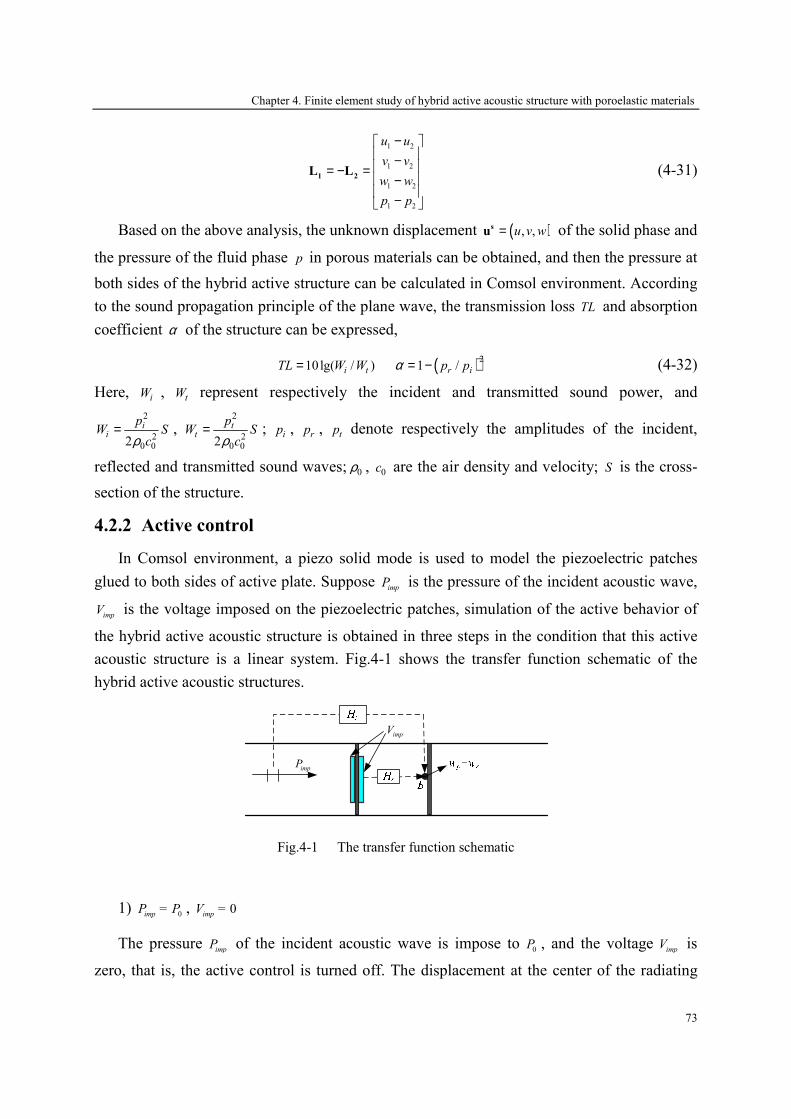
Chapter 4. Finite element study of hybrid active acoustic structure with poroelastic materials
73
1 2
1 2
1 2
1 2
u u
v v
w w
p p
− − = − = − −
1 2L L (4-31)
Based on the above analysis, the unknown displacement ( ), ,u v w=su of the solid phase and
the pressure of the fluid phase p in porous materials can be obtained, and then the pressure at
both sides of the hybrid active structure can be calculated in Comsol environment. According
to the sound propagation principle of the plane wave, the transmission loss TL and absorption
coefficient α of the structure can be expressed,
10lg( / )i tTL W W= ( )21 /r ip pα = − (4-32)
Here, iW , tW represent respectively the incident and transmitted sound power, and
2
20 02
ii
pW S
cρ= ,
2
20 02
tt
pW S
cρ= ; ip , rp , tp denote respectively the amplitudes of the incident,
reflected and transmitted sound waves; 0ρ , 0c are the air density and velocity; S is the cross-
section of the structure.
4.2.2 Active control
In Comsol environment, a piezo solid mode is used to model the piezoelectric patches
glued to both sides of active plate. Suppose imp
P is the pressure of the incident acoustic wave,
impV is the voltage imposed on the piezoelectric patches, simulation of the active behavior of
the hybrid active acoustic structure is obtained in three steps in the condition that this active
acoustic structure is a linear system. Fig.4-1 shows the transfer function schematic of the
hybrid active acoustic structures.
impP
impV
Fig.4-1 The transfer function schematic
1) 0imp
P = P , 0imp
V =
The pressure imp
P of the incident acoustic wave is impose to 0
P , and the voltage imp
V is
zero, that is, the active control is turned off. The displacement at the center of the radiating
Chapter 4. Finite element study of hybrid active acoustic structure with poroelastic materials
74
plate or the pressure of the acoustic wave at radiating side can be calculated, represented in
( )pw ω . Then the first transfer function of incident wave can be written in Eq. (4-31).
0
( )( )
p
p
wH
P
ωω = (4-33)
2) 0imp
P = , 0imp
V = V
In this step, no more incident wave transmits in hybrid active acoustic structure, and the
active plate is excited by an electric potential 0
V applied to the piezoelectric patches. Once
again, the displacement at the center of the radiating plate or the pressure of the acoustic wave
at radiating side can be calculated, represented in ( )sw ω . Then the second transfer function of
secondary sound source can be written in Eq. (4-34).
0
( )( ) s
s
wH
V
ωω = (4-34)
3) 1imp
P = P , imp s
V = V
Finally, the pressure imp
P of the incident acoustic wave is impose to 1
P , and the optimal
voltage exciting active plate is calculated by Eq. (4-35).
1
( )( )
( )
p
s
s
HV P
H
ωω
ω= − (4-35)
Therefore, the displacement of the radiating plate or the pressure of the acoustic wave at
radiating side can be reduced obviously.
4.3 Numerical results and validations
In this section, the properties of different layers in these hybrid systems are calculated in
the Comsol environment and the acoustic performance of the hybrid systems is validated by
the numerical results of the scattering matrix method.
4.3.1 The radiating plate
The radiating plate used in the hybrid active acoustic structure is an elastic thin plate in
steel with a thickness of 0.2mm, and its physics parameters are given in Table.2-1. In the
Comsol environment, only a quarter of this simply supported plate is modeled because of its
symmetry, which reduces the memory storage and calculation time. Some shape deformations
of the radiating plate are drawn in Fig.4-2 by Comsol environment, lower than the simulation
frequencies.
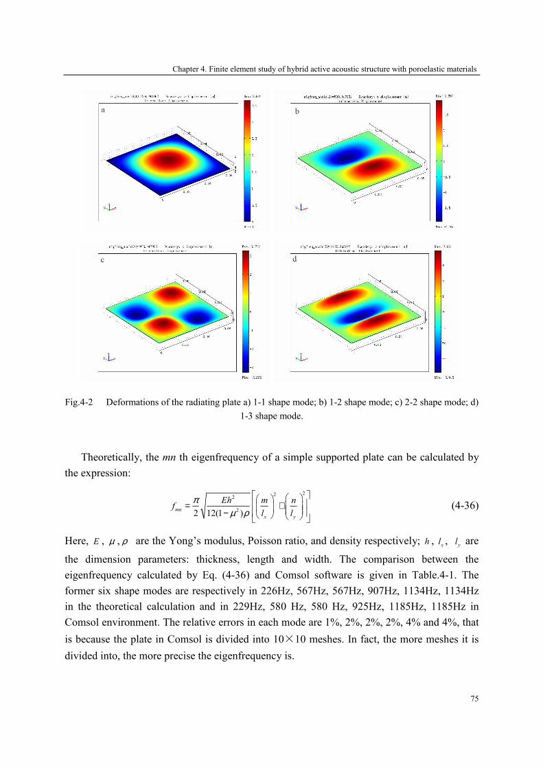
Chapter 4. Finite element study of hybrid active acoustic structure with poroelastic materials
75
Fig.4-2 Deformations of the radiating plate a) 1-1 shape mode; b) 1-2 shape mode; c) 2-2 shape mode; d)
1-3 shape mode.
Theoretically, the mn th eigenfrequency of a simple supported plate can be calculated by
the expression:
222
22 12(1 )mn
x y
Eh m nf
l l
πµ ρ
= + −
(4-36)
Here, E , µ , ρ are the Yong’s modulus, Poisson ratio, and density respectively; h , x
l , y
l are
the dimension parameters: thickness, length and width. The comparison between the
eigenfrequency calculated by Eq. (4-36) and Comsol software is given in Table.4-1. The
former six shape modes are respectively in 226Hz, 567Hz, 567Hz, 907Hz, 1134Hz, 1134Hz
in the theoretical calculation and in 229Hz, 580 Hz, 580 Hz, 925Hz, 1185Hz, 1185Hz in
Comsol environment. The relative errors in each mode are 1%, 2%, 2%, 2%, 4% and 4%, that
is because the plate in Comsol is divided into 10×10 meshes. In fact, the more meshes it is
divided into, the more precise the eigenfrequency is.

Chapter 4. Finite element study of hybrid active acoustic structure with poroelastic materials
76
Table.4-1 Comparison of the eigenfrequency in theoretical and Comsol results
1-1 mode 1-2 mode 2-1 mode 2-2 mode 1-3 mode 3-1 mode
Eq. (4-36) 226 Hz 567 Hz 567 Hz 907 Hz 1134 Hz 1134 Hz
Comsol 229 Hz 580 Hz 580 Hz 925 Hz 1185 Hz 1185 Hz
Relative error 1% 2% 2% 2% 4% 4%
Fig.4-3 shows the transmission loss of this radiating plate in simulation results: the
scattering matrix method and the finite element method in Comsol. The two results show the
first resonance frequency of the radiating plate is adjacent to 230Hz, and good agreement can
be obtained for low frequencies. Unfortunately, the second peak of transmission loss cannot
be displayed in the scattering matrix method because only the first vibration mode is used to
calculate the transfer matrix of this plate.
200 400 600 800 1000 1200 1400 1600 1800 20000
5
10
15
20
25
30
35
40
45
Frequency / Hz
TL / dB
FE Comsol model
scattering matrix
Fig.4-3 The transmission loss of the radiating plate with simple support
4.3.2 The active plate
The active plate used in the hybrid active acoustic structure is the elastic thin steel plate
bonded on piezoelectric patches with a thickness of 0.5mm on both sides, and its physics
parameters are given in Table.3-1. The configuration of this active plate is shown in Fig.4-4.
In the Comsol environment, a quarter of the active plate is modeled with 10×10 meshes.
Some shape deformations of the active plate are drawn in Fig.4-5 by Comsol environment,
lower than the simulation frequencies. The former six shape modes are respectively in 317Hz,
612 Hz, 612 Hz, 1095Hz, 1374Hz and 1690Hz in Comsol environment, which has an obvious
shift compared to the six shape modes of the radiating plate, due to the piezoelectric patches
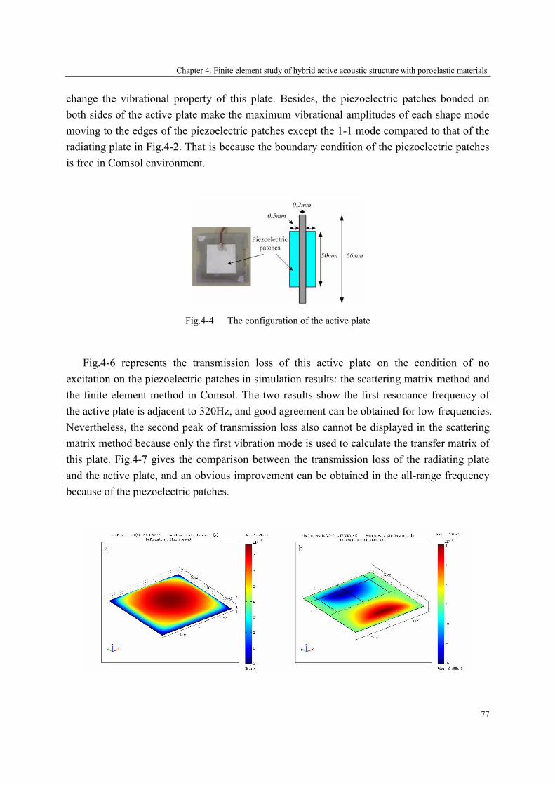
Chapter 4. Finite element study of hybrid active acoustic structure with poroelastic materials
77
change the vibrational property of this plate. Besides, the piezoelectric patches bonded on
both sides of the active plate make the maximum vibrational amplitudes of each shape mode
moving to the edges of the piezoelectric patches except the 1-1 mode compared to that of the
radiating plate in Fig.4-2. That is because the boundary condition of the piezoelectric patches
is free in Comsol environment.
Fig.4-4 The configuration of the active plate
Fig.4-6 represents the transmission loss of this active plate on the condition of no
excitation on the piezoelectric patches in simulation results: the scattering matrix method and
the finite element method in Comsol. The two results show the first resonance frequency of
the active plate is adjacent to 320Hz, and good agreement can be obtained for low frequencies.
Nevertheless, the second peak of transmission loss also cannot be displayed in the scattering
matrix method because only the first vibration mode is used to calculate the transfer matrix of
this plate. Fig.4-7 gives the comparison between the transmission loss of the radiating plate
and the active plate, and an obvious improvement can be obtained in the all-range frequency
because of the piezoelectric patches.
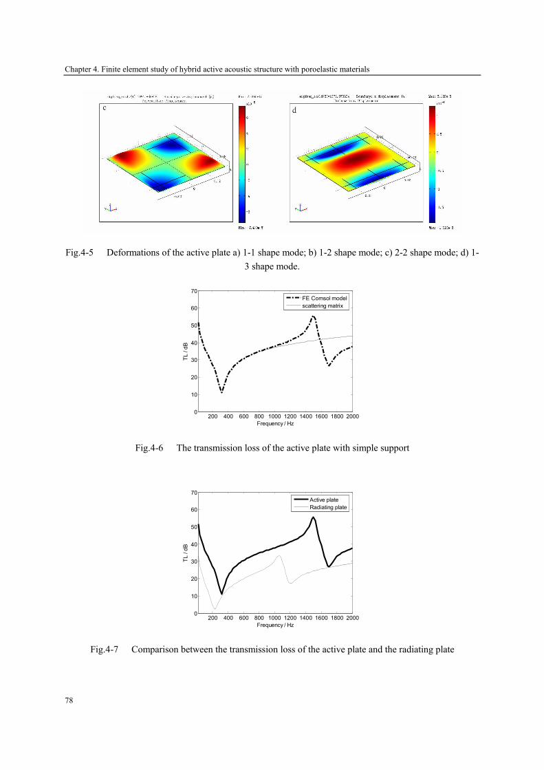
Chapter 4. Finite element study of hybrid active acoustic structure with poroelastic materials
78
Fig.4-5 Deformations of the active plate a) 1-1 shape mode; b) 1-2 shape mode; c) 2-2 shape mode; d) 1-
3 shape mode.
200 400 600 800 1000 1200 1400 1600 1800 20000
10
20
30
40
50
60
70
Frequency / Hz
TL / dB
FE Comsol model
scattering matrix
Fig.4-6 The transmission loss of the active plate with simple support
200 400 600 800 1000 1200 1400 1600 1800 20000
10
20
30
40
50
60
70
Frequency / Hz
TL / dB
Active plate
Radiating plate
Fig.4-7 Comparison between the transmission loss of the active plate and the radiating plate
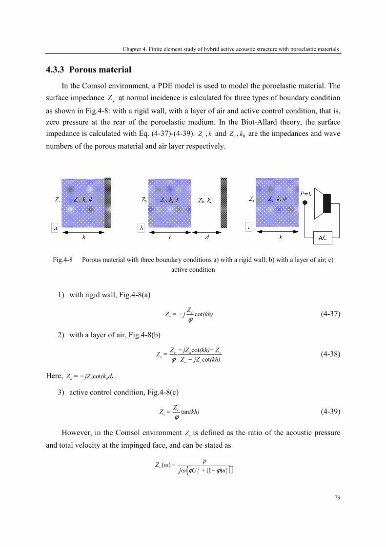
Chapter 4. Finite element study of hybrid active acoustic structure with poroelastic materials
79
4.3.3 Porous material
In the Comsol environment, a PDE model is used to model the poroelastic material. The
surface impedance sZ at normal incidence is calculated for three types of boundary condition
as shown in Fig.4-8: with a rigid wall, with a layer of air and active control condition, that is,
zero pressure at the rear of the poroelastic medium. In the Biot-Allard theory, the surface
impedance is calculated with Eq. (4-37)-(4-39). c
Z , k and 0
Z , 0k are the impedances and wave
numbers of the porous material and air layer respectively.
Fig.4-8 Porous material with three boundary conditions a) with a rigid wall; b) with a layer of air; c)
active condition
1) with rigid wall, Fig.4-8(a)
cotc
s
ZZ = j (kh)
φ− (4-37)
2) with a layer of air, Fig.4-8(b)
cot
cot
c a c
s
a c
Z jZ (kh)+ ZZ =
Z jZ (kh)φ−
− (4-38)
Here, 0
cota 0
Z = jZ (k d)− .
3) active control condition, Fig.4-8(c)
tanc
s
ZZ = (kh)
φ (4-39)
However, in the Comsol environment s
Z is defined as the ratio of the acoustic pressure
and total velocity at the impinged face, and can be stated as
( )3 3
( )(1 )
s f s
pZ ω =
jω U + uφ φ−

Chapter 4. Finite element study of hybrid active acoustic structure with poroelastic materials
80
( )( ){ } 12
22 12 22/ 1 1 /
z= p jω p ω ρ + + ρ ρ wφ φ
− ⋅ − ɶ ɶ ɶ (4-40)
For confirming that the PDE model modeling this poroelastic material is valid in Comsol,
we calculate the ratios of the surface impedance and the air impedance 0/sZ Z by applying
Biot-Allard theory to some examples given in Table.4-2, which have been validated with
experimental measurements [162]. Comparing to the results obtained in Comsol with the
finite element method, good agreement can be noted for the three boundary conditions as
shown in Fig.4-9.
Table.4-2 Parameters of porous materials (felt)
Thickness 25 cm
Porosity 0.93
Resistivity 23150 rayls/m
Young’s modulus 12000 Pa
Mass density 50 kg/m3
Tortuosity 1.1
Viscous length 44µm
Thermal length 121µm
Poisson ratio 0.06
0 500 1000 1500 2000 25000
1
2
3
4
5
Frequency / Hz
Re(Zs/Z0)
0 500 1000 1500 2000 2500-5
0
5
Frequency / Hz
Im(Zs/Z0)
Biot-Allard Theory
FE Comsol model
a
0 500 1000 1500 2000 25000
2
4
6
8
Frequency / Hz
Re(Zs/Z0)
0 500 1000 1500 2000 2500-5
0
5
Frequency / Hz
Im(Zs/Z0)
Biot-Allard Theory
FE Comsol model
b

Chapter 4. Finite element study of hybrid active acoustic structure with poroelastic materials
81
0 500 1000 1500 2000-2
0
2
4
6
Frequency / Hz
Re(Zs/Z0)
0 500 1000 1500 2000-2
-1
0
1
2
3
Frequency / Hz
Im(Zs/Z0)
Biot-Allard Theory
FE Comsol model
c
Fig.4-9 Comparison between the surface impedance in Biot-Allard theory and FE Comsol model a) with
rigid wall; b) with a layer of 12cm air; c) active condition
In this chapter, the properties of the porous material used in the hybrid active acoustic
structure are shown in Table.2-1. The acoustic performance of this porous material is plotted
in Fig.4-10 with simulation results: the scattering matrix method and the finite element
method in Comsol. In Comsol environment, the first resonance frequency of this material is
about 360Hz, and its absorption coefficient is excellent, more than 0.8 over the range of
frequencies of interest, whereas its transmission loss is less than 7dB. However, no resonance
frequency can be obtained in the scattering matrix method, due to this porous material is
elastic which makes an equivalent fluid with a rigid frame unsuitable to model this material.
200 400 600 800 1000 1200 1400 1600 1800 20000.75
0.8
0.85
0.9
0.95
Frequenc / Hz
Absorption
200 400 600 800 1000 1200 1400 1600 1800 20004
5
6
7
Frequency / Hz
TL / dB
FE Comsol model
scattering matrix
Fig.4-10 The acoustic performance of the porous material

Chapter 4. Finite element study of hybrid active acoustic structure with poroelastic materials
82
4.3.4 Hybrid active acoustic structure
Some examples of the hybrid active acoustic structure with different cores will be
presented in this section. The transmission loss of these packages is given in Comsol
environment and the scattering matrix method, and the two results show that obvious
improvements can be obtained with active control.
A. A double-wall structure with air gap
A configuration of the double-wall active acoustic structure with air gap of 20mm
thickness is shown in Fig.4-11. An error sensor is positioned in point A.
Fig.4-11 The configuration of the double-wall structure with air gap
In the Comsol environment, the 5×5×1, 5×5×2, and 4×4×1 3D meshes are applied
respectively to the plate, the air gap and the piezoelectric patches. The transmission loss of
this double-wall structure without active control is shown in Fig.4-12 with numerical results:
the scattering matrix method and the finite element method. The resonance frequencies of the
double-wall structure are 340Hz and 460Hz in Comsol environment, and 350Hz and 470Hz in
the scattering matrix method; the relative error of the resonance frequency between the two
methods is less than 3%. Besides, the transmission loss in the two methods has a good
agreement lower than 600Hz: less than 5dB in difference. However, more differences in the
transmission loss has been displayed over 600Hz, that is because only the first vibration mode
is used to calculate the transfer matrix of the radiating plate and active plate. Fig.4-13 gives
the transmission loss of this double-wall structure in Comsol environment with control the
pressure in point A. It shows that the active control is valid until 1660Hz, and about 15dB of
the transmission loss can be improved at the resonance frequencies.
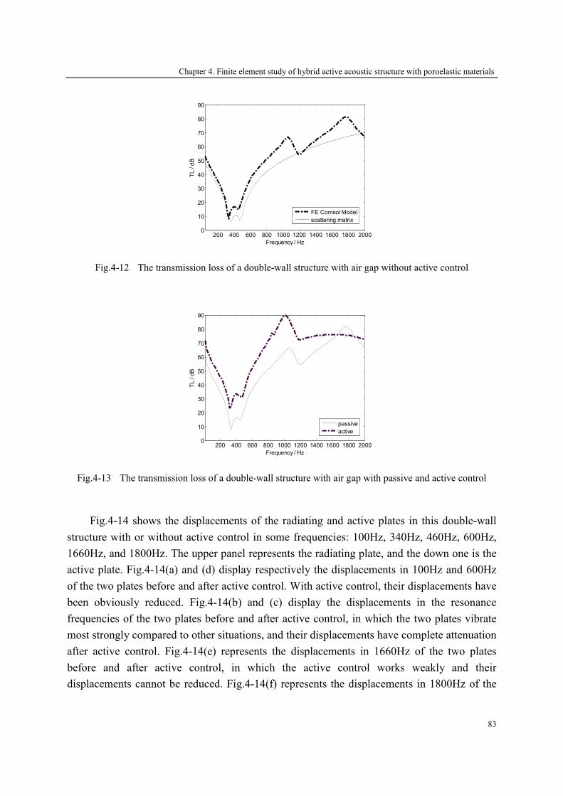
Chapter 4. Finite element study of hybrid active acoustic structure with poroelastic materials
83
200 400 600 800 1000 1200 1400 1600 1800 20000
10
20
30
40
50
60
70
80
90
Frequency / Hz
TL / dB
FE Comsol Model
scattering matrix
Fig.4-12 The transmission loss of a double-wall structure with air gap without active control
200 400 600 800 1000 1200 1400 1600 1800 20000
10
20
30
40
50
60
70
80
90
Frequency / Hz
TL / dB
passive
active
Fig.4-13 The transmission loss of a double-wall structure with air gap with passive and active control
Fig.4-14 shows the displacements of the radiating and active plates in this double-wall
structure with or without active control in some frequencies: 100Hz, 340Hz, 460Hz, 600Hz,
1660Hz, and 1800Hz. The upper panel represents the radiating plate, and the down one is the
active plate. Fig.4-14(a) and (d) display respectively the displacements in 100Hz and 600Hz
of the two plates before and after active control. With active control, their displacements have
been obviously reduced. Fig.4-14(b) and (c) display the displacements in the resonance
frequencies of the two plates before and after active control, in which the two plates vibrate
most strongly compared to other situations, and their displacements have complete attenuation
after active control. Fig.4-14(e) represents the displacements in 1660Hz of the two plates
before and after active control, in which the active control works weakly and their
displacements cannot be reduced. Fig.4-14(f) represents the displacements in 1800Hz of the
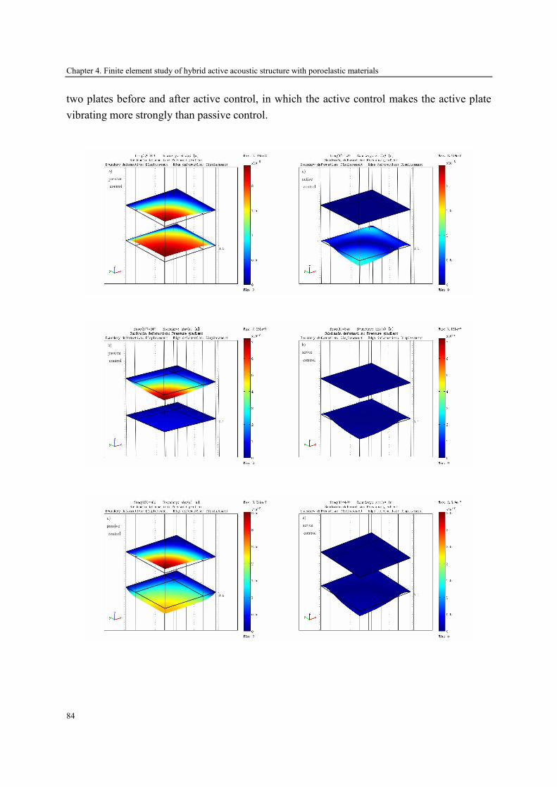
Chapter 4. Finite element study of hybrid active acoustic structure with poroelastic materials
84
two plates before and after active control, in which the active control makes the active plate
vibrating more strongly than passive control.
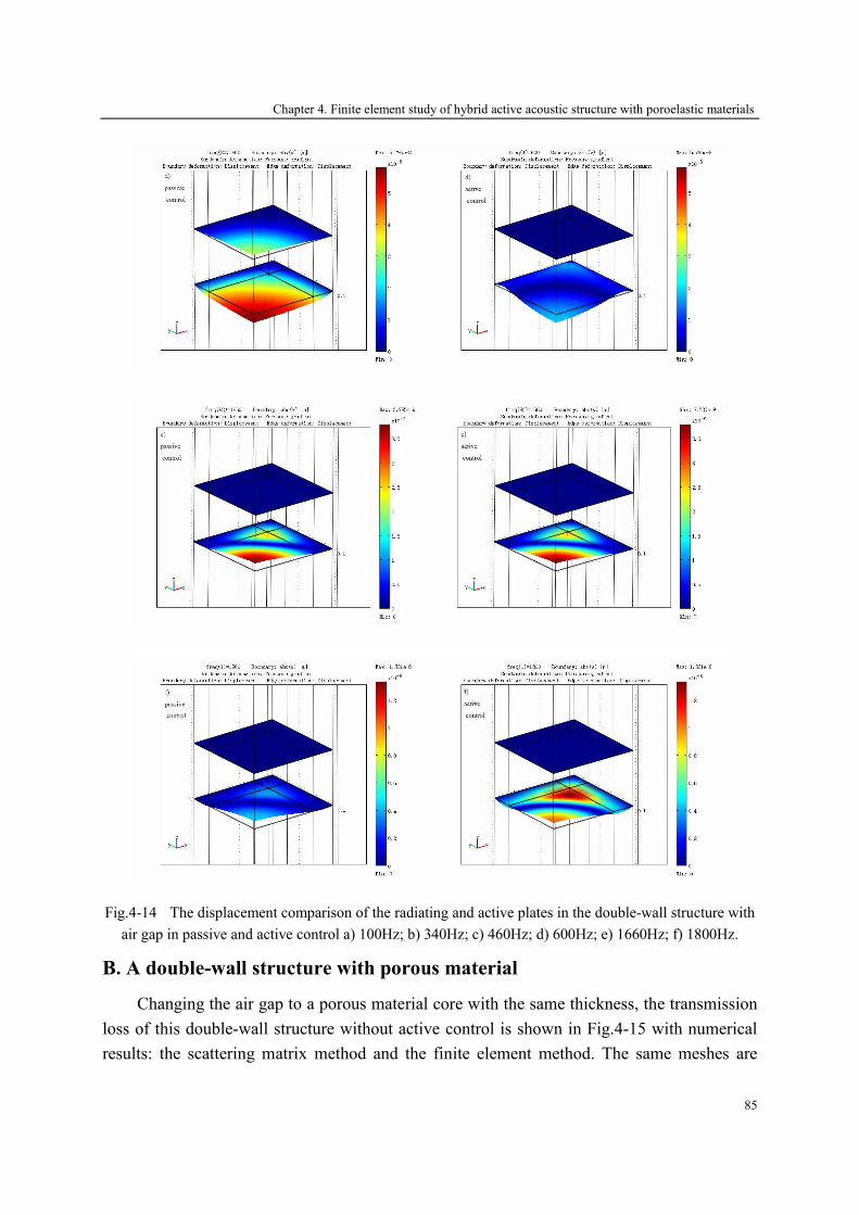
Chapter 4. Finite element study of hybrid active acoustic structure with poroelastic materials
85
Fig.4-14 The displacement comparison of the radiating and active plates in the double-wall structure with
air gap in passive and active control a) 100Hz; b) 340Hz; c) 460Hz; d) 600Hz; e) 1660Hz; f) 1800Hz.
B. A double-wall structure with porous material
Changing the air gap to a porous material core with the same thickness, the transmission
loss of this double-wall structure without active control is shown in Fig.4-15 with numerical
results: the scattering matrix method and the finite element method. The same meshes are
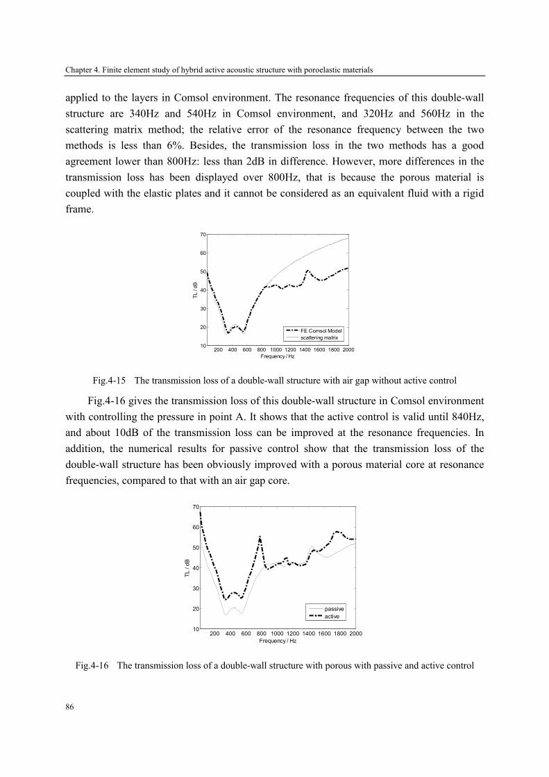
Chapter 4. Finite element study of hybrid active acoustic structure with poroelastic materials
86
applied to the layers in Comsol environment. The resonance frequencies of this double-wall
structure are 340Hz and 540Hz in Comsol environment, and 320Hz and 560Hz in the
scattering matrix method; the relative error of the resonance frequency between the two
methods is less than 6%. Besides, the transmission loss in the two methods has a good
agreement lower than 800Hz: less than 2dB in difference. However, more differences in the
transmission loss has been displayed over 800Hz, that is because the porous material is
coupled with the elastic plates and it cannot be considered as an equivalent fluid with a rigid
frame.
200 400 600 800 1000 1200 1400 1600 1800 200010
20
30
40
50
60
70
Frequency / Hz
TL / dB
FE Comsol Model
scattering matrix
Fig.4-15 The transmission loss of a double-wall structure with air gap without active control
Fig.4-16 gives the transmission loss of this double-wall structure in Comsol environment
with controlling the pressure in point A. It shows that the active control is valid until 840Hz,
and about 10dB of the transmission loss can be improved at the resonance frequencies. In
addition, the numerical results for passive control show that the transmission loss of the
double-wall structure has been obviously improved with a porous material core at resonance
frequencies, compared to that with an air gap core.
200 400 600 800 1000 1200 1400 1600 1800 200010
20
30
40
50
60
70
Frequency / Hz
TL / dB
passive
active
Fig.4-16 The transmission loss of a double-wall structure with porous with passive and active control
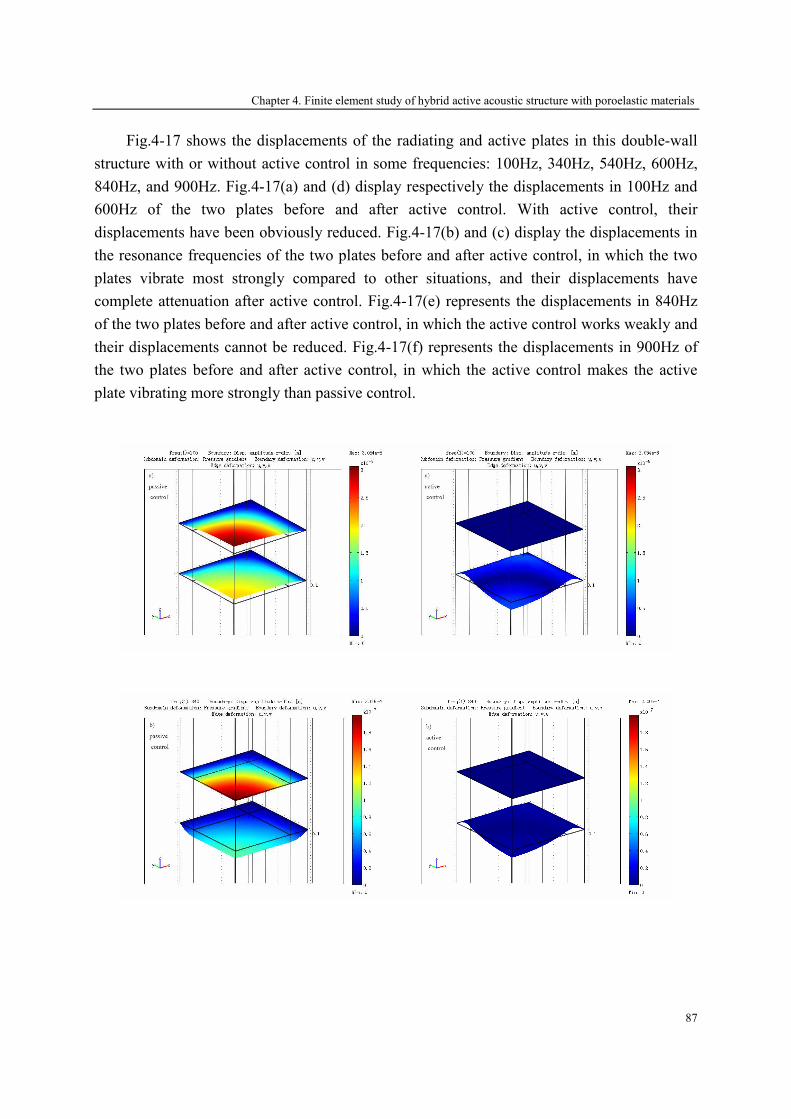
Chapter 4. Finite element study of hybrid active acoustic structure with poroelastic materials
87
Fig.4-17 shows the displacements of the radiating and active plates in this double-wall
structure with or without active control in some frequencies: 100Hz, 340Hz, 540Hz, 600Hz,
840Hz, and 900Hz. Fig.4-17(a) and (d) display respectively the displacements in 100Hz and
600Hz of the two plates before and after active control. With active control, their
displacements have been obviously reduced. Fig.4-17(b) and (c) display the displacements in
the resonance frequencies of the two plates before and after active control, in which the two
plates vibrate most strongly compared to other situations, and their displacements have
complete attenuation after active control. Fig.4-17(e) represents the displacements in 840Hz
of the two plates before and after active control, in which the active control works weakly and
their displacements cannot be reduced. Fig.4-17(f) represents the displacements in 900Hz of
the two plates before and after active control, in which the active control makes the active
plate vibrating more strongly than passive control.

Chapter 4. Finite element study of hybrid active acoustic structure with poroelastic materials
88
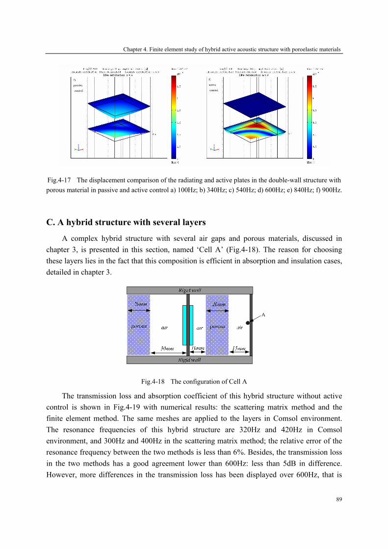
Chapter 4. Finite element study of hybrid active acoustic structure with poroelastic materials
89
Fig.4-17 The displacement comparison of the radiating and active plates in the double-wall structure with
porous material in passive and active control a) 100Hz; b) 340Hz; c) 540Hz; d) 600Hz; e) 840Hz; f) 900Hz.
C. A hybrid structure with several layers
A complex hybrid structure with several air gaps and porous materials, discussed in
chapter 3, is presented in this section, named ‘Cell A’ (Fig.4-18). The reason for choosing
these layers lies in the fact that this composition is efficient in absorption and insulation cases,
detailed in chapter 3.
Fig.4-18 The configuration of Cell A
The transmission loss and absorption coefficient of this hybrid structure without active
control is shown in Fig.4-19 with numerical results: the scattering matrix method and the
finite element method. The same meshes are applied to the layers in Comsol environment.
The resonance frequencies of this hybrid structure are 320Hz and 420Hz in Comsol
environment, and 300Hz and 400Hz in the scattering matrix method; the relative error of the
resonance frequency between the two methods is less than 6%. Besides, the transmission loss
in the two methods has a good agreement lower than 600Hz: less than 5dB in difference.
However, more differences in the transmission loss has been displayed over 600Hz, that is
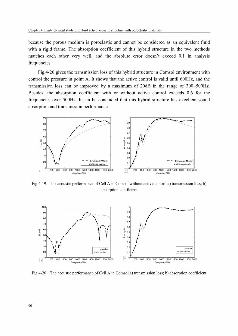
Chapter 4. Finite element study of hybrid active acoustic structure with poroelastic materials
90
because the porous medium is poroelastic and cannot be considered as an equivalent fluid
with a rigid frame. The absorption coefficient of this hybrid structure in the two methods
matches each other very well, and the absolute error doesn’t exceed 0.1 in analysis
frequencies.
Fig.4-20 gives the transmission loss of this hybrid structure in Comsol environment with
control the pressure in point A. It shows that the active control is valid until 600Hz, and the
transmission loss can be improved by a maximum of 20dB in the range of 300~500Hz.
Besides, the absorption coefficient with or without active control exceeds 0.6 for the
frequencies over 500Hz. It can be concluded that this hybrid structure has excellent sound
absorption and transmission performance.
200 400 600 800 1000 1200 1400 1600 1800 200010
20
30
40
50
60
70
80
90
Frequency / Hz
TL / dB
FE Comsol Model
scatteing matrix
a
200 400 600 800 1000 1200 1400 1600 1800 2000
0
0.1
0.2
0.3
0.4
0.5
0.6
0.7
0.8
0.9
1
Frequency / Hz
Absorption
FE Comsol Model
scattering matrix
b
Fig.4-19 The acoustic performance of Cell A in Comsol without active control a) transmission loss; b)
absorption coefficient
200 400 600 800 1000 1200 1400 1600 1800 200010
20
30
40
50
60
70
80
90
100
Frequency / Hz
TL / dB
passive
active
a
200 400 600 800 1000 1200 1400 1600 1800 2000
0
0.1
0.2
0.3
0.4
0.5
0.6
0.7
0.8
0.9
1
Frequency / Hz
Absorption
passive
active
b
Fig.4-20 The acoustic performance of Cell A in Comsol a) transmission loss; b) absorption coefficient

Chapter 4. Finite element study of hybrid active acoustic structure with poroelastic materials
91
Fig.4-21 shows the displacements of the radiating and active plates in this hybrid
structure with or without active control in some frequencies: 100Hz, 320Hz, 360Hz and
1600Hz. Fig.4-21(a) displays the displacements in 100Hz of the two plates before and after
active control. With active control, their displacements have been weakly reduced. Fig.4-21(b)
display the displacements in the first resonance frequency of the two plates before and after
active control, in which the two plates vibrate most strongly compared to other situations, and
their displacements have no attenuation after active control, shown equally in Fig.4-20(a).
Fig.4-21(c) represents the displacements in 360Hz of the two plates before and after active
control, in which the active control works strongly and the displacement of the radiating plate
has been reduced obviously. Fig.4-21(d) represents the displacements in 1600Hz of the two
plates before and after active control, in which the active control makes the active plate
vibrating more strongly than passive control.
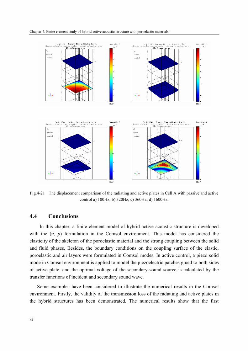
Chapter 4. Finite element study of hybrid active acoustic structure with poroelastic materials
92
Fig.4-21 The displacement comparison of the radiating and active plates in Cell A with passive and active
control a) 100Hz; b) 320Hz; c) 360Hz; d) 1600Hz.
4.4 Conclusions
In this chapter, a finite element model of hybrid active acoustic structure is developed
with the (u, p) formulation in the Comsol environment. This model has considered the
elasticity of the skeleton of the poroelastic material and the strong coupling between the solid
and fluid phases. Besides, the boundary conditions on the coupling surface of the elastic,
poroelastic and air layers were formulated in Comsol modes. In active control, a piezo solid
mode in Comsol environment is applied to model the piezoelectric patches glued to both sides
of active plate, and the optimal voltage of the secondary sound source is calculated by the
transfer functions of incident and secondary sound wave.
Some examples have been considered to illustrate the numerical results in the Comsol
environment. Firstly, the validity of the transmission loss of the radiating and active plates in
the hybrid structures has been demonstrated. The numerical results show that the first
Chapter 4. Finite element study of hybrid active acoustic structure with poroelastic materials
93
resonance frequencies and the transmission loss of the radiating and active plates are in good
agreement in the scattering matrix method and the finite element model in Comsol
environment. However, the second peak of transmission loss cannot be displayed in the
scattering matrix method because only the first vibration mode is applied to calculate the
transfer matrix of the two plates. Secondly, the surface impedance of the porous materials was
validated by Biot’s theory for different boundary conditions. Nevertheless, the results in the
scattering matrix method doesn’t agree well with that in Comsol environment, due to the
elastic behavior of the porous material which makes an equivalent fluid with a rigid frame
unsuitable to model this material.
Lastly, the dynamic responses of some hybrid active acoustic structure have been studied
under plane wave excitation, in which piezoelectric patches are added onto the excited plate
behaving as a secondary vibrational source. The resonance frequencies of these hybrid
structures have been calculated by the scattering matrix method and Comsol environment, and
the relative error of the resonance frequencies between the two methods is less than 6%.
Besides, more than 10dB gain in sound insulation of the hybrid active acoustic structure can
be obtained at resonance frequencies with active control, which have been validated in
chapter 3.
In addition, these hybrid structures are not too large, just 66mm in edge length. Hence,
for controlling the noise in a large-area domain, these structures become ineffective and
useless because of its limited dimension. In this case, a multi-cell active acoustic structure
concept will be realized by compositing these hybrid structures in chapter 6.

Chapter 5. Experiments of hybrid active acoustic structure based on two source-location method
95
Chapter 5
Experiments of hybrid active acoustic structure
based on two source-location method
In the preceding chapters, the numerical results in the acoustic performance of the hybrid
active acoustic structure have been obtained by the scattering matrix method and the finite
element method with Comsol software. The two methods agree each other very well in some
frequency range, while some differences exhibit in the resonance or higher frequencies
because of the poroelastic materials. Therefore, some experiments should be carried out to
validate the numerical results of the hybrid active packages.
The most common approach for measuring the transmission loss of the acoustic structures
is in the reverberation room and in the standing wave tube. In the reverberation room method,
some types of equipment such as reverberation room and high quality microphone are
required. Besides, the dimension of the tested structure should be large enough. In the
standing wave tube, the transmission loss of the tested structure is determined by the incident
power in decomposition theory and the transmitted power in the plane wave approximation
assuming an anechoic termination [165-168]. If a two-microphone random-excitation
technique is used, the sound pressure may be decomposed into its incident and reflected
waves [159]. And the transmitted wave is obtained by the third microphone. The major
drawback of this method is that an anechoic termination is required. In practice, an anechoic
termination could be constructed using a long exhaust tube, high absorbing materials, horn
shapes pipes or an active sound anechoic termination [159]. However, a fully anechoic
termination is difficult to be built, particularly one that is effective at low frequencies.
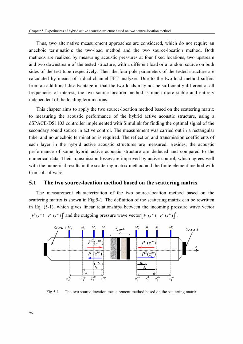
Chapter 5. Experiments of hybrid active acoustic structure based on two source-location method
96
Thus, two alternative measurement approaches are considered, which do not require an
anechoic termination: the two-load method and the two source-location method. Both
methods are realized by measuring acoustic pressures at four fixed locations, two upstream
and two downstream of the tested structure, with a different load or a random source on both
sides of the test tube respectively. Then the four-pole parameters of the tested structure are
calculated by means of a dual-channel FFT analyzer. Due to the two-load method suffers
from an additional disadvantage in that the two loads may not be sufficiently different at all
frequencies of interest, the two source-location method is much more stable and entirely
independent of the loading terminations.
This chapter aims to apply the two source-location method based on the scattering matrix
to measuring the acoustic performance of the hybrid active acoustic structure, using a
dSPACE-DS1103 controller implemented with Simulink for finding the optimal signal of the
secondary sound source in active control. The measurement was carried out in a rectangular
tube, and no anechoic termination is required. The reflection and transmission coefficients of
each layer in the hybrid active acoustic structures are measured. Besides, the acoustic
performance of some hybrid active acoustic structure are deduced and compared to the
numerical data. Their transmission losses are improved by active control, which agrees well
with the numerical results in the scattering matrix method and the finite element method with
Comsol software.
5.1 The two source-location method based on the scattering matrix
The measurement characterization of the two source-location method based on the
scattering matrix is shown in Fig.5-1. The definition of the scattering matrix can be rewritten
in Eq. (5-1), which gives linear relationships between the incoming pressure wave vector
( ) ( )T
up dnP z P z
+ − and the outgoing pressure wave vector ( ) ( )T
up dnP z P z
− + .
up( )P z+
up( )P z−
dn( )P z−
dn( )P z+
up
4zup
3zup
2z up
1z dn
4zdn
3zdn
2zdn
1z
1M ′
2M ′
3M ′
4M ′
1M2
M3
M4
M
Fig.5-1 The two source-location measurement method based on the scattering matrix

Chapter 5. Experiments of hybrid active acoustic structure based on two source-location method
97
11 12
21 22
( ) ( ),
( ) ( )
up up
dn dn
D DP z P z
D DP z P z
− +
+ −
= ⋅ =
D D (5-1)
Here, 11
D and 21
D represents respectively anechoic reflection and transmission coefficients
associated with the left side incoming waves; 22
D and 12
D represents respectively anechoic
reflection and transmission coefficients associated with the right side incoming waves.
Eq. (5-1) shows that the incoming and outgoing pressures on both sides of the samples are
needed to calculate the scattering matrix, but in fact, the total sound pressure at 1 4
M ∼ is
measured by microphones; hence, it requires at least two measuring points on each side to
separate the incoming and outgoing pressures from the total pressure. However, due to the
existence of standing waves in the tube, the spacing between the two measuring points can not
be equal to an integer multiple of the half-wavelength of the maximum measuring frequency,
and must satisfy the condition of 0 max
2 / 5d c f< [161], where 0
c is the sound speed and max
f is
the maximum measuring frequency. In addition, if some measuring points are adjacent to the
nodes of some singularity frequencies, the measurement error will be increased due to the low
signal-to-noise ratio (SNR), hence, more measuring points can be set on both sides of the
tested structure to eliminate this phenomenon. In this chapter, four measuring points in each
side were used, and the scattering matrix can be written as follows when one of the sources
switches on:
(1) (1) (2) (2)
(1) (1) (2) (2)
( ) ( ) ( ) ( )
( ) ( ) ( ) ( )
up up up up
dn dn dn dn
P z P z P z P z
P z P z P z P z
− + − +
+ − + −
= ⋅ = ⋅
D D (5-2)
Here, ( ) ( )i upP z± and ( ) ( )i dnP z± represent the incoming and outgoing waves in the i source
switched on, 1, 2i = .
Eq. (5-2) can be transmitted into the form of a matrix:
(1) (2) (1) (2)
(1) (2) (1) (2)
( ) ( ) ( ) ( )
( ) ( ) ( ) ( )
up up up up
dn dn dn dn
P z P z P z P z
P z P z P z P z
− − + +
+ + − −
= ⋅
D (5-3)
Therefore, the scattering matrix D is calculated by the expression in follows:
1
2 2 2 2.out inP P
−
× × = D (5-4)
Here(1) (2)
(1) (2)2 2
2 2
( ) ( )
( ) ( )
up up
out
dn dn
P z P zP
P z P z
− −
+ +××
=
,
(1) (2)
(1) (2)2 2
2 2
( ) ( )
( ) ( )
up up
in
dn dn
P z P zP
P z P z
+ +
− −××
=
.
In fact, the measured pressures at 1, ,4
M ⋯ and 1, ,4
M ′⋯ by microphones is the total sound
pressure, hence, we need decompose the incident, reflected and transmitted waves according
to the plane wave propagation principle:

Chapter 5. Experiments of hybrid active acoustic structure based on two source-location method
98
1 1
2 2
3 3
( )
1
( ) ( )
2
( ) ( )
3
( )
4
1 1( )
( ) ( )
( ) ( )
( )
i up
jkd jkdi up i up
jkd jkdi up i up
jkd jkdi up
P z
e eP z P z
e eP z P z
e eP z
− +
− −
−
=
1 1
2 2
3 3
( )
1
( ) ( )
2
( ) ( )
3
( )
4
1 1( )
( ) ( )
( ) ( )
( )
i dn
jkd jkdi dn i dn
jkd jkdi dn i dn
jkd jkdi dn
P z
e eP z P z
e eP z P z
e eP z
− +
− −
−
=
(5-5)
After some mathematic operations, the incoming and outgoing waves on both sides of the
tested structure can be expressed as:
( ) 1( )
( ) 2 4 4 2 2 4 4 1
( ). . . ( )
( )
i upH H
up up up i up
ki up
P zMd Md Md P z
P z
+ −
− × × × ×
= (5-6)
( ) 1( )
( ) 2 4 4 2 2 4 4 1
( ). . . ( )
( )
i dnH H
dn dn dn i dn
ki dn
P zMd Md Md P z
P z
− −
+ × × × ×
= (5-7)
Here, the superscript ‘H’ denotes the conjugate transpose; ( ) ( )i up
kP z and ( ) ( )i dn
kP z represent the
pressures given by microphones, 1, 2i = , 1, , 4k = ⋯ . 1 3, ,d d⋯ are the spacing between the
microphones.
1 2 3
1 2 34 2
1
1
Tjkd jkd jkd
up
jkd jkd jkd
e e eMd
e e e− − −×
=
1 2 3
1 2 34 2
1
1
Tjkd jkd jkd
dn
jkd jkd jkd
e e eMd
e e e
− − −
×
=
(5-8)
Therefore, the transmission loss and absorption coefficient can be calculated by the
scattering matrix, 21D and 11D , respectively:
( )2 2
21 1110lg 1/ 1TL D Dα= = − (5-9)
5.2 Experimental disposition
The experiment was realized in LFMA, at Ecole Centrale de Lyon. All measurements
were carried out in a rectangular tube. The cross-section of this rectangular tube (seeing in
Fig.5-2) was 66×66mm2, and its cut-off frequency was 2500Hz, which allowed a normal
plane wave to be transmitted in the tube for the frequencies lower than 2500Hz.
Fig.5-2 The rectangular tube used in measurements

Chapter 5. Experiments of hybrid active acoustic structure based on two source-location method
99
The experimental disposition consisted of four parts: the source, the test section, the
control system and the data processing. The two sources used in experiments generated white
noise signals with the emission band from 50 to 2000 Hz, and one of the sources located on
the upstream of the test section was the primary source. The piezoelectric ceramics were
added onto the active plate behaving as a secondary source.
The tested structure was installed in the test section, and each layer of the structure was
fixed on the frame which can slide freely in the tube. These frames can be applied to isolate
air layers with different thickness, and quickly form different multilayer active acoustic
structures. The radiating and active plates have an area slightly larger than the cross section of
the tube, which makes the two plates adhered to the frame, whereas the porous material has
the same cross section of the tube, just embedded in the frame, shown in Fig.5-3. The
parameters of the plates and porous materials were given in Table.2-1.
66
mm
(a) The plates adhered on the frame (b) The porous embedded in the frame
Fig.5-3 The layers with the frames
In the two source-location measurement, Siglab dynamic system analyzer generated the
broadband noise signals and then transmitted them to the source 1 or source 2. In active
control, the error sensor signal was amplified and filtered, and then was controlled by the
classical FXLMS algorithm implemented on a dSPACE-DS1103 controller with Simulink to
find out the control signal. Fig.5-4 showed the characterization of the control system and data
processing. The microphones used for acoustic pressure measurements are B&K ¼ 4939-type.
The pressure signals were then pre-amplified with a gain of 10dB.
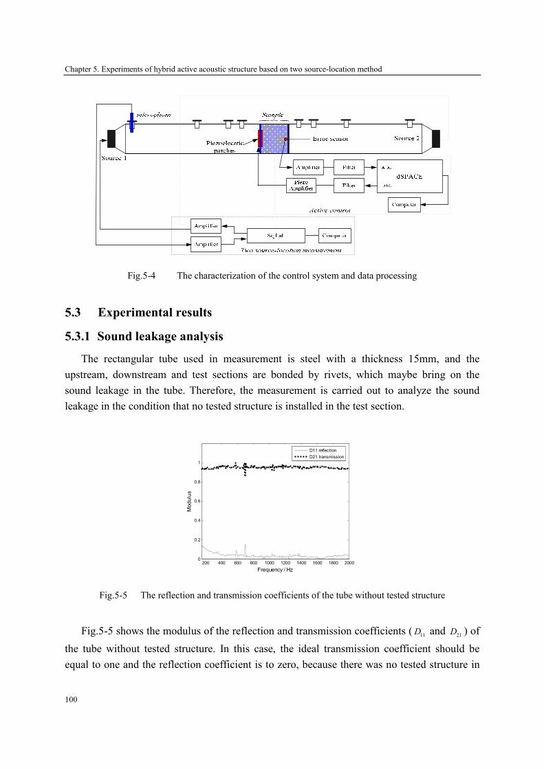
Chapter 5. Experiments of hybrid active acoustic structure based on two source-location method
100
��� ��
Fig.5-4 The characterization of the control system and data processing
5.3 Experimental results
5.3.1 Sound leakage analysis
The rectangular tube used in measurement is steel with a thickness 15mm, and the
upstream, downstream and test sections are bonded by rivets, which maybe bring on the
sound leakage in the tube. Therefore, the measurement is carried out to analyze the sound
leakage in the condition that no tested structure is installed in the test section.
200 400 600 800 1000 1200 1400 1600 1800 20000
0.2
0.4
0.6
0.8
1
Frequency / Hz
Modulus
D11 reflection
D21 transmission
Fig.5-5 The reflection and transmission coefficients of the tube without tested structure
Fig.5-5 shows the modulus of the reflection and transmission coefficients (11
D and 21
D ) of
the tube without tested structure. In this case, the ideal transmission coefficient should be
equal to one and the reflection coefficient is to zero, because there was no tested structure in
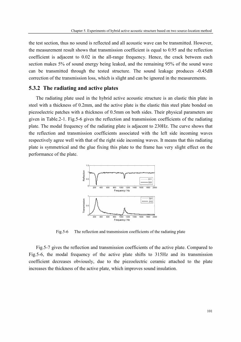
Chapter 5. Experiments of hybrid active acoustic structure based on two source-location method
101
the test section, thus no sound is reflected and all acoustic wave can be transmitted. However,
the measurement result shows that transmission coefficient is equal to 0.95 and the reflection
coefficient is adjacent to 0.02 in the all-range frequency. Hence, the crack between each
section makes 5% of sound energy being leaked, and the remaining 95% of the sound wave
can be transmitted through the tested structure. The sound leakage produces -0.45dB
correction of the transmission loss, which is slight and can be ignored in the measurements.
5.3.2 The radiating and active plates
The radiating plate used in the hybrid active acoustic structure is an elastic thin plate in
steel with a thickness of 0.2mm, and the active plate is the elastic thin steel plate bonded on
piezoelectric patches with a thickness of 0.5mm on both sides. Their physical parameters are
given in Table.2-1. Fig.5-6 gives the reflection and transmission coefficients of the radiating
plate. The modal frequency of the radiating plate is adjacent to 230Hz. The curve shows that
the reflection and transmission coefficients associated with the left side incoming waves
respectively agree well with that of the right side incoming waves. It means that this radiating
plate is symmetrical and the glue fixing this plate to the frame has very slight effect on the
performance of the plate.
200 400 600 800 1000 1200 1400 1600 1800 20000
0.5
1
1.5
Frequency / Hz
Reflection
D11
D22
200 400 600 800 1000 1200 1400 1600 1800 20000
0.5
1
Frequency / Hz
Transmission D21
D12
Fig.5-6 The reflection and transmission coefficients of the radiating plate
Fig.5-7 gives the reflection and transmission coefficients of the active plate. Compared to
Fig.5-6, the modal frequency of the active plate shifts to 315Hz and its transmission
coefficient decreases obviously, due to the piezoelectric ceramic attached to the plate
increases the thickness of the active plate, which improves sound insulation.
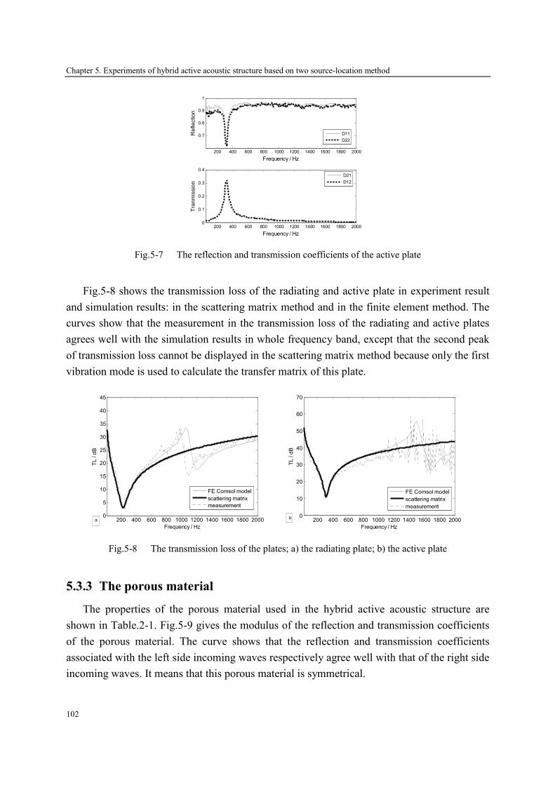
Chapter 5. Experiments of hybrid active acoustic structure based on two source-location method
102
200 400 600 800 1000 1200 1400 1600 1800 2000
0.7
0.8
0.9
1
Frequency / Hz
Reflection
200 400 600 800 1000 1200 1400 1600 1800 20000
0.1
0.2
0.3
0.4
Frequency / Hz
Tranmission
D21
D12
D11
D22
Fig.5-7 The reflection and transmission coefficients of the active plate
Fig.5-8 shows the transmission loss of the radiating and active plate in experiment result
and simulation results: in the scattering matrix method and in the finite element method. The
curves show that the measurement in the transmission loss of the radiating and active plates
agrees well with the simulation results in whole frequency band, except that the second peak
of transmission loss cannot be displayed in the scattering matrix method because only the first
vibration mode is used to calculate the transfer matrix of this plate.
200 400 600 800 1000 1200 1400 1600 1800 20000
5
10
15
20
25
30
35
40
45
Frequency / Hz
TL / dB
FE Comsol model
scattering matrix
measurement
a
200 400 600 800 1000 1200 1400 1600 1800 2000
0
10
20
30
40
50
60
70
Frequency / Hz
TL / dB
FE Comsol model
scattering matrix
measurement
b
Fig.5-8 The transmission loss of the plates; a) the radiating plate; b) the active plate
5.3.3 The porous material
The properties of the porous material used in the hybrid active acoustic structure are
shown in Table.2-1. Fig.5-9 gives the modulus of the reflection and transmission coefficients
of the porous material. The curve shows that the reflection and transmission coefficients
associated with the left side incoming waves respectively agree well with that of the right side
incoming waves. It means that this porous material is symmetrical.

Chapter 5. Experiments of hybrid active acoustic structure based on two source-location method
103
200 400 600 800 1000 1200 1400 1600 1800 20000.2
0.3
0.4
0.5
Frequency / Hz
Reflection
D11
D22
200 400 600 800 1000 1200 1400 1600 1800 20000.4
0.5
0.6
0.7
0.8
Frequency / Hz
Transmission
D21
D12
Fig.5-9 The reflection and transmission coefficients of the porous material
The absorption coefficient and transmission loss of this porous material is plotted in Fig.5-
10 with measurement and simulation results: in the scattering matrix method and in the finite
element method. In Comsol environment and measurement, the first resonance frequency of
this material is about 360Hz, and its absorption coefficient is excellent, more than 0.8 over the
range of frequencies of interest, whereas its transmission loss is less than 7dB. However, no
resonance frequency can be obtained in the scattering matrix method, due to this porous
material is elastic which makes an equivalent fluid with a rigid frame unsuitable to model this
material.
200 400 600 800 1000 1200 1400 1600 1800 2000
0.8
0.9
1
Frequency / Hz
Absorption
200 400 600 800 1000 1200 1400 1600 1800 20004
5
6
7
8
Frequency / Hz
TL / dB
FE Comsol model
scattering matrix
measurement
Fig.5-10 Comparison of numerical and experimental results of the porous material
5.3.4 Hybrid active acoustic structure
A. A double-wall structure with air gap
The transmission loss of the double-wall active acoustic structure with air gap shown in
Fig.4-11 is curved in Fig.5-11 with measurement and simulation results: in the scattering

Chapter 5. Experiments of hybrid active acoustic structure based on two source-location method
104
matrix method and in the finite element method. Without active control, the comparison
shows that the transmission loss in measurement has a good agreement with that in the
numerical result of the finite element method in all-range frequency. However, more
differences in the transmission loss of the results between measurement and the scattering
matrix method has been displayed over the resonance frequency, that is because only the first
vibration mode is used to calculate the transfer matrix of the radiating plate and active plate.
200 400 600 800 1000 1200 1400 1600 1800 20000
10
20
30
40
50
60
70
80
90
100
Frequency / Hz
TL / dB
FE Comsol Model
scattering matrix
measurement
Fig.5-11 Comparison of numerical and experimental results of a double-wall structure with air gap
without active control
: The first mode frequency of the active plate
: The resonance frequency of the structure
In active control, one error sensor is located at the center of the radiating plate, and the
minimum pressure is used as the control objective. The error signal is controlled by the
classical FXLMS algorithm implemented on a dSPACE-DS1103 controller to find out the
best signal exciting the piezoelectric ceramics. Besides, the sound wave radiated by the source
1 in Fig.5-4 is used as the reference signal. Fig.5-12 shows the configuration of the active
control. The experimental signals of this error sensor are shown in Fig.5-13 with or without
active control. Obvious reduction can be seen after active control is applied, and the
convergence time is short.
Fig.5-12 The configuration of the active control

Chapter 5. Experiments of hybrid active acoustic structure based on two source-location method
105
Fig.5-13 The error sensor signals before and after active control
Fig.5-14 shows the experimental results in the transmission loss of this double-wall
structure with passive or active control. The resonance frequencies of the double-wall
structure are 340Hz and 460Hz in numerical result (seeing in Fig.4-13), and 350Hz and
440Hz in measurement; the relative error between the two methods is less than 5%. The
curves in Fig.5-14 shows that about 15dB gain is obtained near the resonance frequencies in
measurement, and no improvements are realized at frequencies above 500Hz with active
control; however, the results in Fig.4-13 in chapter 4 shows that the active control is valid
until 1660Hz, and about 15dB of the transmission loss can be obtained at the resonance
frequencies. The reason lies in the fact that the active control is operated only for frequencies
less than 500Hz in the experiment. Note that no improvement is obtained under 100Hz in the
experiment due to very low voltage imposed on the piezoelectric ceramic leading to an overly
weak secondary source.
200 400 600 800 1000 1200 1400 1600 1800 20000
10
20
30
40
50
60
70
80
90
Frequency / Hz
TL / dB
passive
active
Fig.5-14 The transmission loss of the double-wall structure with air gap in measurement with or without
active control;
: The first mode frequency of the active plate
: The resonance frequency of the structure
B. A double-wall structure with porous material

Chapter 5. Experiments of hybrid active acoustic structure based on two source-location method
106
The transmission loss of the double-wall active acoustic structure with porous material is
presented in Fig.5-15 with measurement and simulation results: in the scattering matrix
method and in the finite element method. Without active control, the comparison shows that
the transmission loss in measurement is in good agreement with that in the numerical result of
the finite element method in all-range frequency. However, more differences in the
transmission loss of the results between measurement and the scattering matrix method has
been displayed over 800Hz, that is because only the first vibration mode is used to calculate
the transfer matrix of the radiating plate and active plate, besides, the porous material is
coupled with the elastic plates and it cannot be considered as an equivalent fluid with a rigid
frame.
200 400 600 800 1000 1200 1400 1600 1800 200010
20
30
40
50
60
70
80
Frequency / Hz
TL / dB
FE Comsol Model
scattering matrix
measurement
Fig.5-15 Comparison of numerical and experimental results of the double-wall structure with porous
material without active control
: The first mode frequency of the active plate
: The resonance frequency of the structure
Fig.5-16 shows the experimental results in the transmission loss of this double-wall
structure with passive or active control. The resonance frequencies of the double-wall
structure are 340Hz and 540Hz in the numerical results (seeing in Fig.4-16), and 320Hz and
515Hz in the experiment; the relative error between the two methods is less than 7%. The
results in Fig.4-16 in chapter 4 shows that the active control is valid until 800Hz, and the
transmission loss can be improved around resonance frequencies by about 10 dB; whereas,
the curves in Fig.5-16 shows that about 10dB gain is obtained near the resonance frequencies
under 500Hz, and no improvement is obtained under 120Hz in the experiment due to very low
voltage imposed on the piezoelectric ceramic.
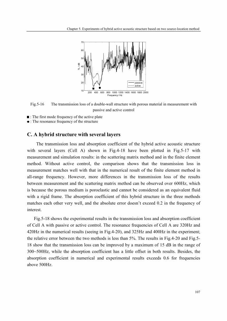
Chapter 5. Experiments of hybrid active acoustic structure based on two source-location method
107
200 400 600 800 1000 1200 1400 1600 1800 200010
20
30
40
50
60
70
Frequency / Hz
TL / dB
passive
active
Fig.5-16 The transmission loss of a double-wall structure with porous material in measurement with
passive and active control
: The first mode frequency of the active plate
: The resonance frequency of the structure
C. A hybrid structure with several layers
The transmission loss and absorption coefficient of the hybrid active acoustic structure
with several layers (Cell A) shown in Fig.4-18 have been plotted in Fig.5-17 with
measurement and simulation results: in the scattering matrix method and in the finite element
method. Without active control, the comparison shows that the transmission loss in
measurement matches well with that in the numerical result of the finite element method in
all-range frequency. However, more differences in the transmission loss of the results
between measurement and the scattering matrix method can be observed over 600Hz, which
is because the porous medium is poroelastic and cannot be considered as an equivalent fluid
with a rigid frame. The absorption coefficient of this hybrid structure in the three methods
matches each other very well, and the absolute error doesn’t exceed 0.2 in the frequency of
interest.
Fig.5-18 shows the experimental results in the transmission loss and absorption coefficient
of Cell A with passive or active control. The resonance frequencies of Cell A are 320Hz and
420Hz in the numerical results (seeing in Fig.4-20), and 325Hz and 400Hz in the experiment;
the relative error between the two methods is less than 5%. The results in Fig.4-20 and Fig.5-
18 show that the transmission loss can be improved by a maximum of 15 dB in the range of
300~500Hz, while the absorption coefficient has a little offset in both results. Besides, the
absorption coefficient in numerical and experimental results exceeds 0.6 for frequencies
above 500Hz.

Chapter 5. Experiments of hybrid active acoustic structure based on two source-location method
108
200 400 600 800 1000 1200 1400 1600 1800 200010
20
30
40
50
60
70
80
90
100
Frequency / Hz
TL / dB
FE Comsol Model
scatteing matrix
measrement
a
200 400 600 800 1000 1200 1400 1600 1800 2000
0
0.1
0.2
0.3
0.4
0.5
0.6
0.7
0.8
0.9
1
Frequency / Hz
Absorption
FE Comsol Model
scattering matrix
Experiment
b
Fig.5-17 Comparison of numerical and experimental results of Cell A without active control; a)
transmission loss; b) absorption coefficient
: The first mode frequency of the active plate
: The resonance frequency of the structure
200 400 600 800 1000 1200 1400 1600 1800 200010
20
30
40
50
60
70
80
90
100
Frequency / Hz
TL / dB
passive
active
a
200 400 600 800 1000 1200 1400 1600 1800 2000
0.1
0.2
0.3
0.4
0.5
0.6
0.7
0.8
0.9
1
Frequency / Hz
Absorption
passive
active
b
Fig.5-18 The acoustic performance of Cell A in measurement with passive and active control; a)
transmission loss; b) absorption coefficient
: The first mode frequency of the active plate
: The resonance frequency of the structure
5.4 Error analysis of the measurement
In this section, the measurement error of the two source-location method is analyzed in
order to evaluate the accuracy of the transmission loss calculated by the measured pressures.
Indeed, the transmission loss herein is obtained by measuring the pressures on both sides of
the tested structure; hence, the error of TLdB depends on the measured pressure’s error. Eq. (5-
6) and (5-7) show that the incoming and outgoing waves on both sides of the tested structure
are related to the microphone’s error and their position error; while the position error is weak
and can be neglected, only the microphone’s error should be considered. For convenience of
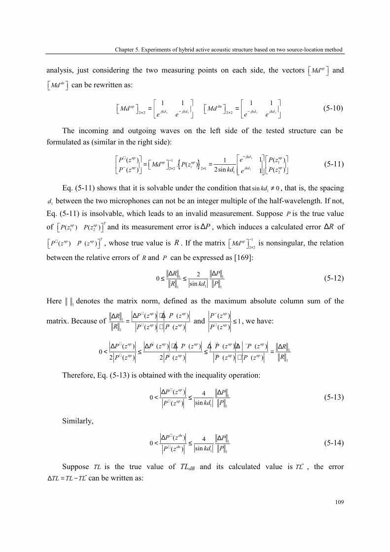
Chapter 5. Experiments of hybrid active acoustic structure based on two source-location method
109
analysis, just considering the two measuring points on each side, the vectors upMd and
dnMd can be rewritten as:
1 12 2
1 1up
jkd jkdMd
e e−×
=
1 1
dn
2 2
1 1
jkd jkdMd
e e−×
=
(5-10)
The incoming and outgoing waves on the left side of the tested structure can be
formulated as (similar in the right side):
{ }1
1
11
2 2 2 11 2
1 ( )( ) 1. ( )
2sin ( )( ) 1
jkd upup
up up
i upup jkd
e P zP zMd P z
kd P zP z e
−+−
− × ×
= =
(5-11)
Eq. (5-11) shows that it is solvable under the condition that1
sin 0kd ≠ , that is, the spacing
1d between the two microphones can not be an integer multiple of the half-wavelength. If not,
Eq. (5-11) is insolvable, which leads to an invalid measurement. Suppose P is the true value
of 1 2( ) ( )T
up upP z P z and its measurement error is P∆ , which induces a calculated error R∆ of
( ) ( )T
up upP z P z
+ − , whose true value is R . If the matrix 1
2 2
upMd−
× is nonsingular, the relation
between the relative errors of R and P can be expressed as [169]:
1 1
11 1
20
sin
R P
R kd P
∆ ∆≤ ≤ (5-12)
Here 1
denotes the matrix norm, defined as the maximum absolute column sum of the
matrix. Because of 1
1
( ) ( )
( ) ( )
up up
up up
P z P zR
R P z P z
+ −
+ −
∆ + ∆∆=
+ and
( )1
( )
up
up
P z
P z
−
+≤ , we have:
1
1
( ) ( ) ( ) ( ) ( )0
2 ( ) 2 ( ) ( ) ( )
up up up up up
up up up up
P z P z P z P z P z R
RP z P z P z P z
+ + − + −
+ + + −
∆ ∆ + ∆ ∆ + ∆ ∆< ≤ ≤ =
+
Therefore, Eq. (5-13) is obtained with the inequality operation:
1
1 1
( ) 40
sin( )
up
up
P z P
kd PP z
+
+
∆ ∆< ≤ (5-13)
Similarly,
1
1 1
( ) 40
sin( )
dn
dn
P z P
kd PP z
+
+
∆ ∆< ≤ (5-14)
Suppose TL is the true value of TLdB and its calculated value is *TL , the error *TL TL TL∆ = − can be written as:

Chapter 5. Experiments of hybrid active acoustic structure based on two source-location method
110
1 ( ) / ( )20 lg
1 ( ) / ( )
dn dn
up up
P z P zTL
P z P z
+ +
+ +
− ∆∆ =
− ∆ (5-15)
Eq. (5-15) can be further simplified as [169]:
1 ( ) / ( )20 lg
1 ( ) / ( )
dn dn
up up
P z P zTL
P z P z
+ +
+ +
+ ∆∆ ≤
− ∆ (5-16)
Suppose δ± dB is the microphone’s error, the corresponding maximum relative error of
the sound pressure can be written as / 20/ 10 1P P
δη = ∆ = − , and the range of TL∆ can be
deduced from Eq. (5-13), (5-14) and (5-16):
1
1
1 4 / sin20 lg
1 4 / sin
kdTL
kd
ηη
+∆ ≤
− (5-17)
Equation (5-17) shows that TL∆ depends on 1kd and δ , hence, the function of their
relationships can be drawn in the (0, )π interval, shown in Fig.5-19. To ensure that TL∆ not
exceed 5dB, the condition of 1
(0.3 ) (0.7 )n kd nπ π+ ≤ ≤ + should be satisfied and the microphone’
error must be within ±0.5dB. When the microphone’ error is certain, TL∆ is minimum for
1(0.5 )kd n π= + , 0,1,n = ⋯ , therefore, the spacing between the microphones should be equal to
the 1/4 wavelength integer of frequency of interest.
0.2 0.3 0.4 0.5 0.6 0.7 0.80
5
10
15
20
25
kd / π
∆TL / dB
0.1dB
0.3dB
0.5dB
0.7dB
Fig.5-19 The relationship between ∆TL, the microphone’s error and spacing
5.5 Conclusions
In this chapter, the two source-location method based on the scattering matrix is applied
to measuring the acoustic performance of the hybrid active acoustic structure, using a
dSPACE-DS1103 controller implemented with Simulink for finding the optimal signal. It
proves that the results in measurement are in good agreement with that in simulation, and the
Chapter 5. Experiments of hybrid active acoustic structure based on two source-location method
111
transmission loss of these hybrid structures can be improved obviously with active control in
the resonance frequency.
Besides, more attention should be paid in experimental measurement:
① The spacing between the two measuring points can not be equal to an integer multiple
of the half-wavelength in the measuring frequency, and must satisfy the condition of
0 max2 / 5d c f< .
② Locating the microphones adjacent to the surface of the testes structure must be
avoided, because the surface acoustic field of the test element is inhomogeneous and it
can yield to errors.
③ More measuring points can be set on both sides of the tested structure to avoid that
some measuring points are adjacent to the nodes of some singularity frequencies,
which increases the measurement error due to the low signal-to-noise ratio.
④ The maximum measurement error TL∆ depends on 1kd and the microphone’s error δ .
To ensure that TL∆ not exceed 5dB, the condition of 1
(0.3 ) (0.7 )n kd nπ π+ ≤ ≤ + should
be satisfied and the microphone’ error δ must be within ±0.5dB. When the
microphone’ error δ is certain, TL∆ is minimum for 1
(0.5 )kd n π= + , 0,1,n = ⋯ ,
therefore, the spacing between the microphones should be equal to the 1/4 wavelength
integer of frequency of interest.
⑤ The measuring precision also depends on the installation of the tested structure. The
crack between each section of the tube should be eliminated to prevent the sound
leakage.


Chapter 6. Multi-cell hybrid active acoustic structure concept for noise control over a large surface
113
Chapter 6
Multi-cell hybrid active acoustic structure concept
for noise control over a large surface
In the preceding chapters, some hybrid active acoustic structure, combining passive
method and active control technique, have been validated and their acoustic absorption or/and
transmission performance can be improved over a certain extent. The numerical results of the
scattering matrix method and the finite element method are validated by the experimental data
based on the two source-location method. All the results show that the acoustic performance
of these hybrid active acoustic structure have been improved obviously by active control,
more than 10dB gain in sound insulation can be obtained at resonance frequencies, and
excellent absorption coefficient can be achieved with several poroelastic materials in
appropriate parameters and disposition.
In fact, the hybrid active acoustic structures mentioned in the preceding chapters are small,
just 66mm in length and width, and lower than 10cm in thickness. However, these hybrid
active acoustic structure are planned to be applied to automobiles, aircrafts, buildings and
other engineering applications, in which large-area domain need to be improved in sound
absorption or/and insulation. One way for controlling the noise in a large-area domain is to
augment the dimension of the hybrid active acoustic structure. In this case, the hybrid
structures become more complicate, because these structures may be manufactured in the
form of curves or other complex shape. Besides, the complex response even in the low
frequency range requires that more error sensors and secondary sources should be used for
active control, which results in complicated algorithm. Another way for controlling the noise
in a large-area domain is to juxtapose several cells of the hybrid structure and then to form a

Chapter 6. Multi-cell hybrid active acoustic structure concept for noise control over a large surface
114
multi-cell hybrid structure. In this multi-cell hybrid structure, each cell has its error sensor and
secondary source for active control; the coupling interface between each hybrid cell can be
rigid or elastic. This multi-cell hybrid structure can be disposed in different forms to satisfy
the noise control in a large-area domain.
Based on the second method above, this chapter aims at proposing a multi-cell hybrid
active acoustic structure concept, juxtaposing several single hybrid cells. For example, the
acoustic performance of some two-cell hybrid active acoustic structures is calculated with an
incident plane wave by the finite element method, and the effect on the acoustic properties of
the structures has been discussed with a rigid or elastic coupling interface. Beside, the
interaction between the secondary sources and the error sensors in each cell has also been
considered.
6.1 The multi-cell hybrid active acoustic structure concept
The configuration of the multi-cell hybrid active acoustic structure is drawn in Fig.6-1 by
juxtaposing several single hybrid cells which are disposed in the form of an m n× array
( , 1, 2,3,m n = ⋯ ). The single hybrid cell (seeing in Fig.6-1(a)) consists of an elastic plate, an
active plate with piezoelectric ceramics vibrating as secondary source, and several dissipative
layers such as air, porous materials… Each hybrid cell has an error sensor located near to the
center of the elastic plate for minimizing the sound pressure of the sensor. The multi-cell
hybrid structure is composed by an m n× array of single hybrid cell coupled together by a
rigid or elastic plate (named ‘a separate plate’).
Fig.6-1 The configuration of the hybrid active structure; a) single cell; b) multi-cell hybrid structure
When the separate plate is thick enough and can be considered as a rigid wall, the
coupling between each cell is weak, and then the acoustic performance of the multi-cell
hybrid structure is similar to that of the single hybrid cell. However, when the separate plate is
too thin, the vibration of the elastic and active plates in the single cells will make the sound
wave transmitted by the separate plate. In this case, each error sensor receives not only the

Chapter 6. Multi-cell hybrid active acoustic structure concept for noise control over a large surface
115
direct sound signal from the secondary source in the same single hybrid cell, but also the
indirect sound signal from the secondary source in the other single hybrid cells. Therefore,
active control is complex to carry out.
6.2 Analysis of active control
Suppose that iP is the pressure of the incident plane wave in the i th single hybrid cell, iV
is the voltage imposed on the piezoelectric patches of the i th cell, the active behavior of the
multi-cell hybrid active acoustic structure is obtained in three steps under the condition that
this whole process is linear. Herein considering an m n× array of the multi-cell hybrid active
acoustic structure, the direct and interaction transfer function of the multi-cell hybrid structure
is shown in Fig.6-2.
11sH
12sH
1s nH
11pH
1A 2AnA
Fig.6-2 The transfer function schematic of multi-cell hybrid structure
6.2.1 The primary pathway matrix
The primary pathway matrix is defined as the transfer function between the primary
sources and the error sensors in the multi-cell hybrid structure. Under a plane wave excitation,
the pressure i
P of the incident acoustic wave in each single hybrid cell is equal to 0
P , and the
voltage iV imposed on the piezoelectric ceramics of each cell is zero, that is, the active
control is turned off. The sound pressure at point Ai where the error sensors are located can be
expressed as ( )pkw ω , 1,2, ,k mn= ⋯ . Then the element of the primary pathway matrix can be
written as:
0
( )( ) , 1,2, ,
pk
pk
wH k mn
P
ωω = = ⋯ (6-1)
Therefore, the primary pathway matrix can be written as:
1
2
( )
0 0
0
0
0 0
p
p
p mnmn mn
H
H
H×
=
pH
⋯
⋮
⋮ ⋱
⋯
(6-2)
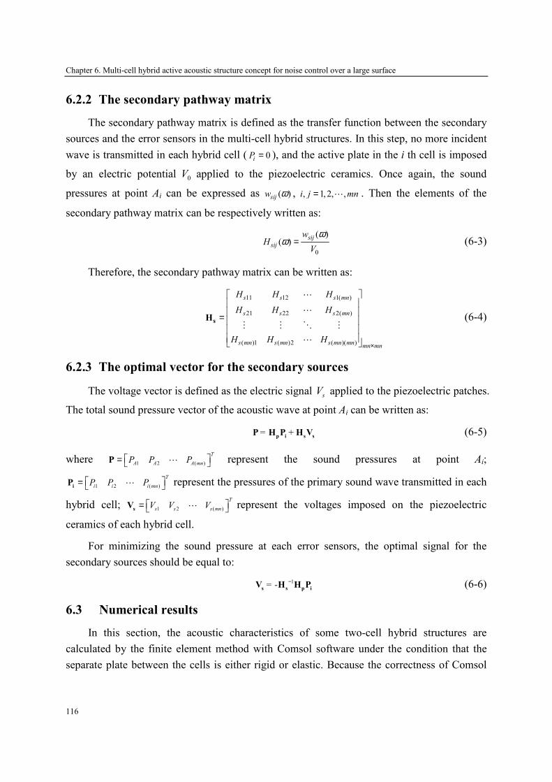
Chapter 6. Multi-cell hybrid active acoustic structure concept for noise control over a large surface
116
6.2.2 The secondary pathway matrix
The secondary pathway matrix is defined as the transfer function between the secondary
sources and the error sensors in the multi-cell hybrid structures. In this step, no more incident
wave is transmitted in each hybrid cell ( 0iP = ), and the active plate in the i th cell is imposed
by an electric potential 0V applied to the piezoelectric ceramics. Once again, the sound
pressures at point Ai can be expressed as ( )sijw ω , , 1, 2, ,i j mn= ⋯ . Then the elements of the
secondary pathway matrix can be respectively written as:
0
( )( )
sij
sij
wH
V
ωω = (6-3)
Therefore, the secondary pathway matrix can be written as:
11 12 1( )
21 22 2( )
( )1 ( )2 ( )( )
s s s mn
s s s mn
s mn s mn s mn mnmn mn
H H H
H H H
H H H×
=
sH
⋯
⋯
⋮ ⋮ ⋱ ⋮
⋯
(6-4)
6.2.3 The optimal vector for the secondary sources
The voltage vector is defined as the electric signal sV applied to the piezoelectric patches.
The total sound pressure vector of the acoustic wave at point Ai can be written as:
= +p i s s
P H P Η V (6-5)
where 1 2 ( )
T
A A A mnP P P = P ⋯ represent the sound pressures at point Ai;
1 2 ( )
T
i i i mnP P P = iP ⋯ represent the pressures of the primary sound wave transmitted in each
hybrid cell; 1 2 ( )
T
s s s mnV V V = sV ⋯ represent the voltages imposed on the piezoelectric
ceramics of each hybrid cell.
For minimizing the sound pressure at each error sensors, the optimal signal for the
secondary sources should be equal to:
1= -
−s s p i
V H H P (6-6)
6.3 Numerical results
In this section, the acoustic characteristics of some two-cell hybrid structures are
calculated by the finite element method with Comsol software under the condition that the
separate plate between the cells is either rigid or elastic. Because the correctness of Comsol
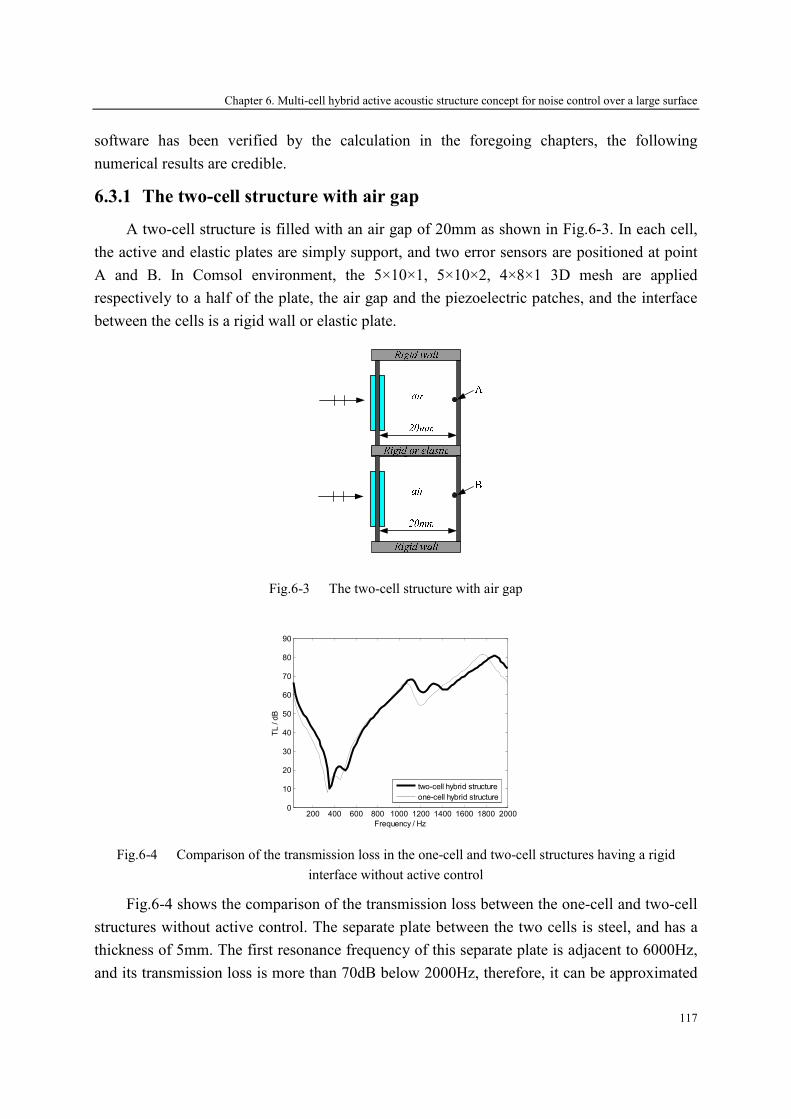
Chapter 6. Multi-cell hybrid active acoustic structure concept for noise control over a large surface
117
software has been verified by the calculation in the foregoing chapters, the following
numerical results are credible.
6.3.1 The two-cell structure with air gap
A two-cell structure is filled with an air gap of 20mm as shown in Fig.6-3. In each cell,
the active and elastic plates are simply support, and two error sensors are positioned at point
A and B. In Comsol environment, the 5×10×1, 5×10×2, 4×8×1 3D mesh are applied
respectively to a half of the plate, the air gap and the piezoelectric patches, and the interface
between the cells is a rigid wall or elastic plate.
Fig.6-3 The two-cell structure with air gap
200 400 600 800 1000 1200 1400 1600 1800 20000
10
20
30
40
50
60
70
80
90
Frequency / Hz
TL / dB
two-cell hybrid structure
one-cell hybrid structure
Fig.6-4 Comparison of the transmission loss in the one-cell and two-cell structures having a rigid
interface without active control
Fig.6-4 shows the comparison of the transmission loss between the one-cell and two-cell
structures without active control. The separate plate between the two cells is steel, and has a
thickness of 5mm. The first resonance frequency of this separate plate is adjacent to 6000Hz,
and its transmission loss is more than 70dB below 2000Hz, therefore, it can be approximated

Chapter 6. Multi-cell hybrid active acoustic structure concept for noise control over a large surface
118
as a rigid interface. Compared to the one-cell structure, the resonance frequency of the two-
cell structure has a slight shift due to the existence of the separate plate, and its transmission
loss has a few changes in whole analysis frequency. It means that the rigid interface between
the cells has little effect on the acoustic performance of the two-cell structure.
Fig.6-5 shows that the transmission loss of the two-cell structure having a rigid interface
before and after active control. With active control, the transmission loss of the two-cell
structure is improved obviously for frequencies lower than 1700Hz. At the resonance
frequencies, about 10dB gain can be obtained at 360Hz and 500Hz respectively.
200 400 600 800 1000 1200 1400 1600 1800 20000
10
20
30
40
50
60
70
80
90
Frequency / Hz
TL / dB
passive
active
Fig.6-5 The transmission loss of the two-cell structure having a rigid interface
When the interface between the cells is elastic and could transmit sound waves, the
results of the transmission loss will be interested in passive and active control. Fig.6-6a
describes the comparison of the transmission loss between the two-cell structure having a
rigid interface of 5mm thickness and that having an elastic one of 1mm thickness without
active control. The first resonance frequency of this elastic separate plate is adjacent to
1200Hz, and its transmission loss is about 20dB at the resonance frequencies, therefore, it can
be approximated as an elastic interface. The curves show that the transmission loss has been
decreased in the latter because the elastic separate plate vibrates and increases the radiating
noises. Meanwhile, the resonance frequency of the latter has been changed because of the
elastic separate plate.
Fig.6-6b describes the transmission loss of this two-cell structure with elastic interface
before and after active control. The curves show that the transmission loss can be improved
obviously below 900Hz with active control. It can be concluded that the property of the two-
cell structure can be changed and its acoustic performance will be reduced when the interface
between the cells is elastic.
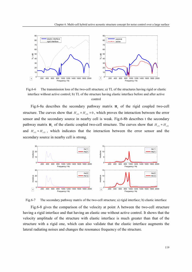
Chapter 6. Multi-cell hybrid active acoustic structure concept for noise control over a large surface
119
200 400 600 800 1000 1200 1400 1600 1800 20000
10
20
30
40
50
60
70
80
90
Frequency / Hz
TL / dB
elastic interface
rigid interface
a
200 400 600 800 1000 1200 1400 1600 1800 2000
0
10
20
30
40
50
60
70
80
90
Frequency / Hz
TL / dB
passive
active
b
Fig.6-6 The transmission loss of the two-cell structure; a) TL of the structures having rigid or elastic
interface without active control; b) TL of the structure having elastic interface before and after active
control
Fig.6-8a describes the secondary pathway matrix s
H of the rigid coupled two-cell
structure. The curves show that 12 21
0s s
H H= = , which proves the interaction between the error
sensor and the secondary source in nearby cell is weak. Fig.6-8b describes t the secondary
pathway matrix s
H of the elastic coupled two-cell structure. The curves show that 11 21s s
H H≈
and 12 22s s
H H≈ , which indicates that the interaction between the error sensor and the
secondary source in nearby cell is strong.
200 400 600 800 1000 1200 1400 1600 1800 20000
10
20
30
Frequency / Hz
modulus
200 400 600 800 1000 1200 1400 1600 1800 20000
10
20
30
Frequency / Hz
modulus
Hs22
Hs12
Hs11
Hs21
a
200 400 600 800 1000 1200 1400 1600 1800 20000
5
10
15
Frequency / Hz
modulus
200 400 600 800 1000 1200 1400 1600 1800 20000
5
10
15
Frequency / Hz
modulus
Hs22
Hs12
Hs11
Hs21
b
Fig.6-7 The secondary pathway matrix of the two-cell structure; a) rigid interface; b) elastic interface
Fig.6-8 gives the comparison of the velocity at point A between the two-cell structure
having a rigid interface and that having an elastic one without active control. It shows that the
velocity amplitude of the structure with elastic interface is much greater than that of the
structure with a rigid one, which can also validate that the elastic interface augments the
lateral radiating noises and changes the resonance frequency of the structure.
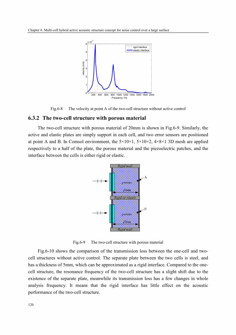
Chapter 6. Multi-cell hybrid active acoustic structure concept for noise control over a large surface
120
200 400 600 800 1000 1200 1400 1600 1800 20000
1
2
3
4
5
6x 10
-3
Frequency / Hz
velocity (m/s)
rigid interface
elastic interface
Fig.6-8 The velocity at point A of the two-cell structure without active control
6.3.2 The two-cell structure with porous material
The two-cell structure with porous material of 20mm is shown in Fig.6-9. Similarly, the
active and elastic plates are simply support in each cell, and two error sensors are positioned
at point A and B. In Comsol environment, the 5×10×1, 5×10×2, 4×8×1 3D mesh are applied
respectively to a half of the plate, the porous material and the piezoelectric patches, and the
interface between the cells is either rigid or elastic.
Fig.6-9 The two-cell structure with porous material
Fig.6-10 shows the comparison of the transmission loss between the one-cell and two-
cell structures without active control. The separate plate between the two cells is steel, and
has a thickness of 5mm, which can be approximated as a rigid interface. Compared to the one-
cell structure, the resonance frequency of the two-cell structure has a slight shift due to the
existence of the separate plate, meanwhile its transmission loss has a few changes in whole
analysis frequency. It means that the rigid interface has little effect on the acoustic
performance of the two-cell structure.
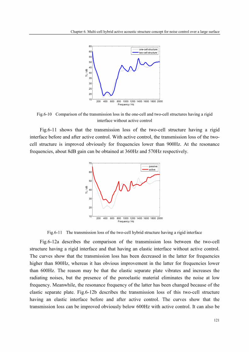
Chapter 6. Multi-cell hybrid active acoustic structure concept for noise control over a large surface
121
200 400 600 800 1000 1200 1400 1600 1800 200015
20
25
30
35
40
45
50
55
60
65
Frequency / Hz
TL / dB
one-cell structure
two-cell structure
Fig.6-10 Comparison of the transmission loss in the one-cell and two-cell structures having a rigid
interface without active control
Fig.6-11 shows that the transmission loss of the two-cell structure having a rigid
interface before and after active control. With active control, the transmission loss of the two-
cell structure is improved obviously for frequencies lower than 900Hz. At the resonance
frequencies, about 8dB gain can be obtained at 360Hz and 570Hz respectively.
200 400 600 800 1000 1200 1400 1600 1800 200010
20
30
40
50
60
70
Frequency / Hz
TL / dB
passive
active
Fig.6-11 The transmission loss of the two-cell hybrid structure having a rigid interface
Fig.6-12a describes the comparison of the transmission loss between the two-cell
structure having a rigid interface and that having an elastic interface without active control.
The curves show that the transmission loss has been decreased in the latter for frequencies
higher than 800Hz, whereas it has obvious improvement in the latter for frequencies lower
than 600Hz. The reason may be that the elastic separate plate vibrates and increases the
radiating noises, but the presence of the poroelastic material eliminates the noise at low
frequency. Meanwhile, the resonance frequency of the latter has been changed because of the
elastic separate plate. Fig.6-12b describes the transmission loss of this two-cell structure
having an elastic interface before and after active control. The curves show that the
transmission loss can be improved obviously below 600Hz with active control. It can also be
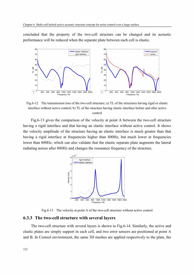
Chapter 6. Multi-cell hybrid active acoustic structure concept for noise control over a large surface
122
concluded that the property of the two-cell structure can be changed and its acoustic
performance will be reduced when the separate plate between each cell is elastic.
200 400 600 800 1000 1200 1400 1600 1800 20000
10
20
30
40
50
60
70
80
Frequency / Hz
TL / dB
elastic interface
rigid interface
a
200 400 600 800 1000 1200 1400 1600 1800 2000
0
10
20
30
40
50
60
70
80
Frequency / Hz
TL / dB
passive
active
b
Fig.6-12 The transmission loss of the two-cell structure; a) TL of the structures having rigid or elastic
interface without active control; b) TL of the structure having elastic interface before and after active
control
Fig.6-13 gives the comparison of the velocity at point A between the two-cell structure
having a rigid interface and that having an elastic interface without active control. It shows
the velocity amplitude of the structure having an elastic interface is much greater than that
having a rigid interface at frequencies higher than 800Hz, but much lower at frequencies
lower than 800Hz, which can also validate that the elastic separate plate augments the lateral
radiating noises after 800Hz and changes the resonance frequency of the structure.
200 400 600 800 1000 1200 1400 1600 1800 20000
1
2
3
4
5
6x 10
-3
Frequency / Hz
velocity (m/s)
rigid interface
elastic interface
Fig.6-13 The velocity at point A of the two-cell structure without active control
6.3.3 The two-cell structure with several layers
The two-cell structure with several layers is shown in Fig.6-14. Similarly, the active and
elastic plates are simply support in each cell, and two error sensors are positioned at point A
and B. In Comsol environment, the same 3D meshes are applied respectively to the plate, the

Chapter 6. Multi-cell hybrid active acoustic structure concept for noise control over a large surface
123
porous material and the piezoelectric patches, and the interface between the cells is either
rigid or elastic.
Fig.6-14 The two-cell structure with several layers
200 400 600 800 1000 1200 1400 1600 1800 200010
20
30
40
50
60
70
80
90
100
Frequency / Hz
TL / dB
one-cell structure
two-cell structure
a 200 400 600 800 1000 1200 1400 1600 1800 20000
0.1
0.2
0.3
0.4
0.5
0.6
0.7
0.8
0.9
1
Frequency / Hz
Absorption
one-cell structure
two-cell structure
b
Fig.6-15 The acoustic performance of the one-cell structure and the two-cell structure having a rigid
interface; a) transmission loss; b) absorption coefficient
Fig.6-15 shows the comparison of the acoustic performance between the one-cell
structure and the two-cell structure having a rigid interface without active control. The
separate plate between the two cells can still be approximated as a rigid interface. Comparing
to the results of the one-cell structure, the resonance frequency of the two-cell structure has a
slight shift due to the existence of the separate plate, meanwhile the transmission loss and
absorption coefficient of this two-cell structure has a few improvements at the band of the
analysis frequencies. It can also be concluded that the rigid separate plate has little effect on
the acoustic performance of the two-cell structure.

Chapter 6. Multi-cell hybrid active acoustic structure concept for noise control over a large surface
124
Fig.6-16 shows that the acoustic performance of the two-cell structure having a rigid
interface before and after active control. With active control, the transmission loss of this two-
cell structure is improved obviously at the band of the resonance frequency, and a maximum
15dB gain can be obtained at frequencies of 300~500Hz. Besides, its absorption coefficient
with or without active control exceeds 0.6 for frequencies over 500Hz. In means this two-cell
structure having a rigid interface still has good sound insulation and absorption performance.
200 400 600 800 1000 1200 1400 1600 1800 200010
20
30
40
50
60
70
80
90
100
Frequency / Hz
TL / dB
passive
active
a 200 400 600 800 1000 1200 1400 1600 1800 20000
0.1
0.2
0.3
0.4
0.5
0.6
0.7
0.8
0.9
1
Frequency / Hz
Absorption
passive
active
b
Fig.6-16 The acoustic performance of the two-cell structure having a rigid interface before and after
active control; a) transmission loss; b) absorption coefficient
200 400 600 800 1000 1200 1400 1600 1800 20000
10
20
30
40
50
60
70
80
90
100
Frequency / Hz
TL / dB
rigid interface
elastic interface
a
200 400 600 800 1000 1200 1400 1600 1800 2000
0
0.1
0.2
0.3
0.4
0.5
0.6
0.7
0.8
0.9
1
Frequency / Hz
Absorption
rigid interface
elastic interface
b
Fig.6-17 The acoustic performance of the two-cell structure a) transmission loss; b) absorption coefficient
Fig.6-17 describes the comparison of the transmission loss and absorption coefficient
between the two-cell structure having a rigid interface and that having an elastic interface
without active control. The curves in Fig.6-17 show that the transmission loss has been
decreased in the latter at frequencies higher than 600Hz, and the absorption coefficient is
reduced obviously over 600Hz compared to that of the two-cell structure having a rigid
interface. The reason may be that the noise radiated by the elastic separate plate enhances the
lateral transmitted wave of the structure. Meanwhile, the resonance frequency of the latter has
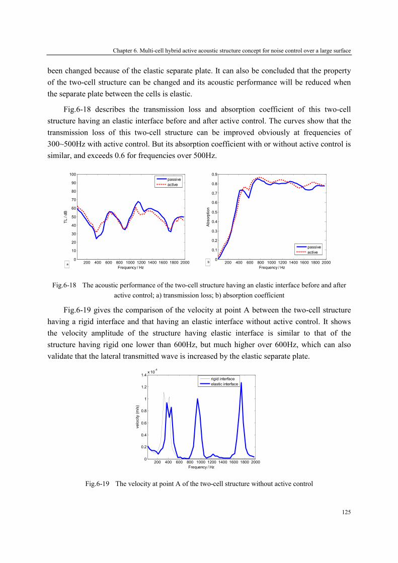
Chapter 6. Multi-cell hybrid active acoustic structure concept for noise control over a large surface
125
been changed because of the elastic separate plate. It can also be concluded that the property
of the two-cell structure can be changed and its acoustic performance will be reduced when
the separate plate between the cells is elastic.
Fig.6-18 describes the transmission loss and absorption coefficient of this two-cell
structure having an elastic interface before and after active control. The curves show that the
transmission loss of this two-cell structure can be improved obviously at frequencies of
300~500Hz with active control. But its absorption coefficient with or without active control is
similar, and exceeds 0.6 for frequencies over 500Hz.
200 400 600 800 1000 1200 1400 1600 1800 20000
10
20
30
40
50
60
70
80
90
100
Frequency / Hz
TL / dB
passive
active
a
200 400 600 800 1000 1200 1400 1600 1800 2000
0
0.1
0.2
0.3
0.4
0.5
0.6
0.7
0.8
0.9
Frequency / Hz
Absorption
passive
active
b
Fig.6-18 The acoustic performance of the two-cell structure having an elastic interface before and after
active control; a) transmission loss; b) absorption coefficient
Fig.6-19 gives the comparison of the velocity at point A between the two-cell structure
having a rigid interface and that having an elastic interface without active control. It shows
the velocity amplitude of the structure having elastic interface is similar to that of the
structure having rigid one lower than 600Hz, but much higher over 600Hz, which can also
validate that the lateral transmitted wave is increased by the elastic separate plate.
200 400 600 800 1000 1200 1400 1600 1800 20000
0.2
0.4
0.6
0.8
1
1.2
1.4x 10
-4
Frequency / Hz
velocity (m/s)
rigid interface
elastic interface
Fig.6-19 The velocity at point A of the two-cell structure without active control
Chapter 6. Multi-cell hybrid active acoustic structure concept for noise control over a large surface
126
Based on the above analysis, it can be concluded that: (1) the multi-cell hybrid active
acoustic structure concept is available for noise control over a large surface by juxtaposing
several single hybrid cells; (2) when the separate plate between the cells is rigid, the
resonance frequency of the multi-cell structure has a slight shift, and its acoustic performance
is similar to that of the one-cell structure; (3) when the separate plate between the cells is
elastic, the resonance frequency of the multi-cell structure changes obviously, and its acoustic
performance is reduced because of the vibration of the elastic separate plate. Therefore, the
interface between the cells in the multi-cell structure should be rigid for holding good sound
insulation or absorption performance.
6.4 Conclusions
In this chapter, the multi-cell hybrid active acoustic structure concept is proposed by
juxtaposing several single hybrid cells. In the multi-cell hybrid structure, the interface
between the cells is rigid or elastic, and each cell has an error sensor for active control with
the objective function of a minimum sound pressure. The direct and indirect interaction
between the primary/secondary sources and the error sensors are given in the form of the
primary and secondary pathway matrices.
For the convenience of analysis, the acoustic properties of the two-cell structures filled
with air gap, porous material or their combinations have been calculated in a plane wave
excitation by the finite element method. The numerical results show that the existence of the
elastic separate plate would change the resonance frequency of the structures and reduce their
acoustic performance.
Chapter 7. Conclusions
127
Chapter 7
Conclusions
A new type of hybrid active acoustic structure combining the passive absorption
properties and active noise control is designed in this thesis. It can be use to reduce the
unwanted room noise in building application or cabin noise in transport application. It has
good acoustic absorption and insulation in wide frequency band. This hybrid active acoustic
structure consists of an elastic plate, an active plate and several layers such as air gaps or
porous material.
7.1 The finished works
The following works have been completed:
1. A hybrid structure allowing good acoustic insulation and absorption for a wide
frequency range have been developed based on passive and active means by using
passive layers and active plate. It is a combination of a sound absorbent system as ‘an
equivalent of the λ/4 resonance absorber’, and a sound insulation system for improving
the transmission loss. The secondary source is realized by an active plate consisting of
two piezoelectric patches bonded to an elastic thin plate in order to improve acoustic
insulation at low and resonances frequencies.
2. The acoustic properties of the developed structure are modeled by the scattering matrix
method. The active plate has been completely described in form of a scattering matrix
and a source strength vector which represents respectively the passive and active
proprieties of this plate. In active control mode, the source strength vector of the active
plate is calculated in order to minimize the sound pressure at the location of the error

Chapter 7. Conclusions
128
sensor. The absorption coefficient and transmission loss of the hybrid structure, are then
deduced from the secondary source vector and the scattering matrix coefficients of all
layers or elements composing this system. Results show that a significant gain on
transmission loss (higher than 15 dB) has been obtained by active control around the
resonance frequency, and the absorption coefficient of this hybrid system exceeds 0.6
over 500Hz.
3. The influence factors which affect the acoustic properties of the developed hybrid active
acoustic structure have been investigated. It can be concluded that more attention should
be paid to the layers located at the front of the active plate when designing a hybrid
structure. The appropriate thickness, porosity and resistivity of the porous material and
the air gap’s thickness should be chosen for getting better acoustic performance of the
hybrid system.
4. The poroelastic material is modeled by the finite element method with the (u, p)
formulation. This model has considered the elasticity of the skeleton of the poroelastic
material and the strong coupling between the solid and fluid phases. The boundary
conditions on the coupling surface of the elastic, poroelastic and air layers were
formulated in Comsol modes. The surface impedance of the poroelastic material was
validated by Biot’s theory for different boundary conditions.
5. Experiments are implemented to evaluate the acoustic properties of the hybrid active
acoustic structure. An experimental device to measure the performance of acoustic
treatments has been developed at the Centre Acoustique of the Ecole Centrale de
Lyon. The hybrid structure is thus directly characterized in the test section. The two
source-location method based on the scattering matrix is applied to measure the acoustic
performance of the hybrid active acoustic structure. A dSPACE-DS1103 controller is
implemented with Simulink for feeding the secondary sound source in active control
mode.
6. A multi-cell hybrid active acoustic structure concept is proposed by juxtaposing several
single hybrid cells for reducing the noise in a large-area domain. The acoustic properties
of the multi-cell hybrid active acoustic structure are calculated for a plane wave
excitation with the finite element method in Comsol environment. It is concluded that
the interface between the cells should be rigid for obtaining good sound insulation or
absorption performance.
Chapter 7. Conclusions
129
7.2 Perspectives
This thesis has developed a hybrid active acoustic structure, which has been validated by
theoretical and experimental means. In order to apply widely this structure to reduce an
unwanted room noise and cabin noise, some further researches should be investigated:
1. Noise control on curved and stiffened plates. The elastic plate used in the developed
hybrid active acoustic structure is rectangular and planar; however, the practical
structures in airplane and automobile cabins are curved, stiffened or more complex.
Therefore, the research on the curved and stiffened plate should be carried out in the
hybrid active acoustic structure in future work.
2. Optimization of the hybrid structure based on a loudspeaker as secondary source. The
secondary source in the developed hybrid structure is realized by piezoelectric ceramics,
and then active control is limited by the voltage on the ceramics. For broadening the
working frequency in active control, a loudspeaker could be used as a secondary source.
Therefore, the number and location of the loudspeakers should be optimized in the
hybrid active acoustic structure. Besides, the near field effect and interaction between
loudspeakers have to be investigated.
3. Environmental effects on the acoustic performance of the hybrid structure. In this thesis,
the acoustic properties of the hybrid structure are calculated under incident plane wave.
However, in engineering application, this hybrid structure would be located on an
environment with much more complicated sound field. The effects of the environment
on the hybrid active acoustic structure also need to be taken into account.
4. Interaction between the secondary sources and error sensors. In this thesis, all the
interactions between the secondary sources and error sensors are considered when
expressing the secondary pathway matrix. However, it could be interesting to reduce the
complexity of the control algorithm, to be able to design configuration allowing neglect
some distant secondary sources. Therefore, in order to obtain the least storage space and
computing time, the effect of the relative location between the secondary sources and
error sensors should be investigated.
5. Experimental research on the multi-cell hybrid structure. The numerical results conclude
that the coupling interface between the cells should be rigid for obtaining good
performance of the multi-cell hybrid structure. For validating this conclusion, the
experiments should be carried out in future.

Notations
131
Notations
φ Porosity
σ Resistivity (rayls/m)
α∞ Tortuosity
Λ Viscous characteristic length (m)
′Λ Thermal characteristic length (m)
s Viscous shape factor
s′ Thermal shape factor
η Dynamic viscosity of air
γ Specific heat ratio
e Thickness of porous sample (m)
P∆ Gradient of acoustic pressure transmitting a porous sample
0ρ Acoustic density (kg/m
3)
0c Acoustic velocity (m/s)
Pr Prandtl number
eρ Effective density of porous sample (kg/m
3)
K Bulk modulus of porous sample sσ Frame stress tensor fσ Fluid stress tensor
11ρ Relative density of frame (kg/m
3)
22ρ Relative density of fluid (kg/m
3)
12ρ Strong inertial coupling between the frame and fluid
bK Bulk modulus of solid phase in vacuum
fK Bulk modulus of fluid phase with the solid phase in motionless
0Z Impedance of air (rayls)
cZ Impedance of porous sample (rayls)
sZ Surface impedance of porous sample at normal incident (rayls)
Notations
132
0k Wave number of air
ck Wave number of porous sample
su Frame displacement fU Fluid displacement
µ Poisson ratio
N Shear modulus of poroelastic medium (N/m2)
T Transfer matrix
D Scattering matrix
α Absorption coefficient
TL Transmission loss (dB)
List of tables
133
List of tables
Table.2-1 The physical parameters of the materials ....................................................................... 37
Table.3-1 Physic parameters of piezoelectric ceramic.................................................................... 53
Table.4-1 Comparison of the eigenfrequency in theoretical and Comsol results ........................... 76
Table.4-2 Parameters of porous materials (felt).............................................................................. 80


List of figures
135
List of figures
Fig.1-1 The schematic of sound cancellation interference .................................................................. 3
Fig.1-2 The electronic sound absorber ................................................................................................ 3
Fig.1-3 Active absorbent using a pressure-release condition .............................................................. 8
Fig.1-4 Passive/active sound absorption system ................................................................................. 8
Fig.1-5 Experimental schema of active absorber in normal incident .................................................. 9
Fig.1-6 The hybrid broadband absorbing liner a) One-cell hybrid absorber; b) Extension of the liner
surface................................................................................................................................... 10
Fig.1-7 Schematic of active structural acoustic control of double panel systems ............................. 12
Fig.1-8 Schematic diagram of active hybrid panels .......................................................................... 12
Fig.2-1 The transfer matrix of an acoustic unit ................................................................................. 19
Fig.2-2 The schematic of a passive system with infinite laterally dimensions.................................. 20
Fig.2-3 The transfer matrix of the air layer ....................................................................................... 28
Fig.2-4 The transfer matrix of the porous material............................................................................ 29
Fig.2-5 The transfer matrix of the elastic plate.................................................................................. 31
Fig.2-6 The transfer matrix of the interface between air layer and porous material ......................... 32
Fig.2-7 The transfer matrix of the interface between air layer, elastic plate and porous material..... 33
Fig.2-8 The total transfer matrix of the air/porous material/air......................................................... 34
Fig.2-9 The total transfer matrix of the porous material/air/plate ..................................................... 35
Fig.2-10 The total transfer matrix of the plate/porous material/plate.................................................. 35
Fig.2-11 The total transfer matrix of the porous material/air/plate/air/porous material/air/plate........ 36
Fig.2-12 Acoustic performance of the / 4λ resonance absorber; a) absorption; b) transmission loss 37
Fig.2-13 Loss power of the / 4λ resonance absorber.......................................................................... 38
Fig.2-14 Acoustic performance of different sound insulation systems; a) absorption; b) transmission
loss ................................................................................................................................ 39
Fig.2-15 Loss power of the different sound insulation systems .......................................................... 39
Fig.2-16 Acoustic performance of the sound absorbent and insulation system; a) absorption
coefficient; b) transmission loss............................................................................................ 40
Fig.2-17 Loss power of the sound absorbent and insulation system ................................................... 40
Fig.3-1 The active plate ..................................................................................................................... 45

List of figures
136
Fig.3-2 The absorbent systems; (a) the λ/4 resonance absorber; (b) the active absorber .................. 46
Fig.3-3 The double-wall active system.............................................................................................. 49
Fig.3-4 General configuration of the multilayer hybrid active acoustic structures ........................... 50
Fig.3-5 The hybrid system in active control with two error sensor................................................... 51
Fig.3-6 The hybrid system in active control with two error sensors ................................................. 52
Fig.3-7 Acoustic performance of the active absorber with different control degree; a) absorption; b)
transmission loss ................................................................................................................... 53
Fig.3-8 Acoustic performance of the plate-air-plate system with different control degree; a)
absorption; b) transmission loss............................................................................................ 54
Fig.3-9 Acoustic performance of the plate-porous-plate system with different control degree; a)
absorption; b) transmission loss............................................................................................ 55
Fig.3-10 Acoustic performance of the plate-air-porous-air-plate system with different control degree;
a) absorption; b) transmission loss........................................................................................ 56
Fig.3-11 Acoustic performance of the hybrid system with an error sensor at point B; a) absorption; b)
transmission loss ................................................................................................................... 56
Fig.3-12 Acoustic performance of the hybrid system with one error sensor at point A; a) absorption; b)
transmission loss ................................................................................................................... 57
Fig.3-13 Acoustic performance of the hybrid system with two error sensor; a) absorption; b)
transmission loss ................................................................................................................... 58
Fig.3-14 Absorption coefficient of the hybrid system with different porous porosities; (a) α with the
different porosity of the porous material 1; (b) α with the different porosity of the porous
material 2 .............................................................................................................................. 59
Fig.3-15 Acoustic performance of the hybrid system in different thicknesses of porous material 1; (a)
absorption coefficient; (b) transmission loss ........................................................................ 59
Fig.3-16 Acoustic performance of the hybrid system in different thicknesses of porous material 2; (a)
absorption coefficient; (b) transmission loss ........................................................................ 60
Fig.3-17 Acoustic performance of the hybrid system in different resistivity of porous material 1; (a)
absorption coefficient α ; (b) transmission loss TL.............................................................. 61
Fig.3-18 Acoustic performance of the hybrid system in different resistivity of porous material 2; (a)
absorption coefficient α ; (b) transmission loss TL.............................................................. 61
Fig.3-19 Acoustic performance of the hybrid system in different thicknesses of air gap 1; (a)
absorption coefficient; (b) transmission loss. ....................................................................... 62
Fig.3-20 Acoustic performance of the hybrid system in different thicknesses of air gap 2; (a)
absorption coefficient; (b) transmission loss ........................................................................ 62
Fig.3-21 Acoustic performance of the hybrid system in different thicknesses of air gap 3; (a)
absorption coefficient; (b) transmission loss ........................................................................ 62
Fig.4-1 The transfer function schematic............................................................................................ 73
Fig.4-2 Deformations of the radiating plate a) 1-1 shape mode; b) 1-2 shape mode; c) 2-2 shape
mode; d) 1-3 shape mode. ..................................................................................................... 75
Fig.4-3 The transmission loss of the radiating plate with simple support ......................................... 76

List of figures
137
Fig.4-4 The configuration of the active plate .................................................................................... 77
Fig.4-5 Deformations of the active plate a) 1-1 shape mode; b) 1-2 shape mode; c) 2-2 shape mode;
d) 1-3 shape mode................................................................................................................. 78
Fig.4-6 The transmission loss of the active plate with simple support.............................................. 78
Fig.4-7 Comparison between the transmission loss of the active plate and the radiating plate......... 78
Fig.4-8 Porous material with three boundary conditions a) with a rigid wall; b) with a layer of air; c)
active condition..................................................................................................................... 79
Fig.4-9 Comparison between the surface impedance in Biot-Allard theory and FE Comsol model a)
with rigid wall; b) with a layer of 12cm air; c) active condition........................................... 81
Fig.4-10 The acoustic performance of the porous material ................................................................. 81
Fig.4-11 The configuration of the double-wall structure with air gap................................................. 82
Fig.4-12 The transmission loss of a double-wall structure with air gap without active control.......... 83
Fig.4-13 The transmission loss of a double-wall structure with air gap with passive and active control
................................................................................................................................ 83
Fig.4-14 The displacement comparison of the radiating and active plates in the double-wall structure
with air gap in passive and active control a) 100Hz; b) 340Hz; c) 460Hz; d) 600Hz; e)
1600Hz; f) 1800Hz. .............................................................................................................. 85
Fig.4-15 The transmission loss of a double-wall structure with air gap without active control.......... 86
Fig.4-16 The transmission loss of a double-wall structure with porous with passive and active control
................................................................................................................................ 86
Fig.4-17 The displacement comparison of the radiating and active plates in the double-wall structure
with porous material in passive and active control a) 100Hz; b) 340Hz; c) 540Hz; d) 600Hz;
e) 840Hz; f) 900Hz. .............................................................................................................. 89
Fig.4-18 The configuration of Cell A.................................................................................................. 89
Fig.4-19 The acoustic performance of Cell A in Comsol without active control a) transmission loss; b)
absorption coefficient............................................................................................................ 90
Fig.4-20 The acoustic performance of Cell A in Comsol a) transmission loss; b) absorption
coefficient ............................................................................................................................. 90
Fig.4-21 The displacement comparison of the radiating and active plates in Cell A with passive and
active control a) 100Hz; b) 320Hz; c) 360Hz; d) 1600Hz. ................................................... 92
Fig.5-1 The two source-location measurement method based on the scattering matrix.................... 96
Fig.5-2 The rectangular tube used in measurements ......................................................................... 98
Fig.5-3 The layers with the frames.................................................................................................... 99
Fig.5-4 The characterization of the control system and data processing......................................... 100
Fig.5-5 The reflection and transmission coefficients of the tube without tested structure .............. 100
Fig.5-6 The reflection and transmission coefficients of the radiating plate .................................... 101
Fig.5-7 The reflection and transmission coefficients of the active plate ......................................... 102
Fig.5-8 The transmission loss of the plates; a) the radiating plate; b) the active plate.................... 102
Fig.5-9 The reflection and transmission coefficients of the porous material .................................. 103
Fig.5-10 Comparison of numerical and experimental results of the porous material........................ 103

List of figures
138
Fig.5-11 Comparison of numerical and experimental results of a double-wall structure with air gap
without active control ......................................................................................................... 104
Fig.5-12 The configuration of the active control............................................................................... 104
Fig.5-13 The error sensor signals before and after active control ..................................................... 105
Fig.5-14 The transmission loss of the double-wall structure with air gap in measurement with or
without active control; ........................................................................................................ 105
Fig.5-15 Comparison of numerical and experimental results of the double-wall structure with porous
material without active control ........................................................................................... 106
Fig.5-16 The transmission loss of a double-wall structure with porous material in measurement with
passive and active control ................................................................................................... 107
Fig.5-17 Comparison of numerical and experimental results of Cell A without active control; a)
transmission loss; b) absorption coefficient........................................................................ 108
Fig.5-18 The acoustic performance of Cell A in measurement with passive and active control; a)
transmission loss; b) absorption coefficient........................................................................ 108
Fig.5-19 The relationship between ∆TL, the microphone’s error and spacing ................................. 110
Fig.6-1 The configuration of the hybrid active structure; a) single cell; b) multi-cell hybrid structure
............................................................................................................................................ 114
Fig.6-2 The transfer function schematic of multi-cell hybrid structure........................................... 115
Fig.6-3 The two-cell structure with air gap ..................................................................................... 117
Fig.6-4 Comparison of the transmission loss in the one-cell and two-cell structures having a rigid
interface without active control........................................................................................... 117
Fig.6-5 The transmission loss of the two-cell structure having a rigid interface............................. 118
Fig.6-6 The transmission loss of the two-cell structure; a) TL of the structures having rigid or elastic
interface without active control; b) TL of the structure having elastic interface before and
after active control .............................................................................................................. 119
Fig.6-7 The secondary pathway matrix of the two-cell structure; a) rigid interface; b) elastic
interface .............................................................................................................................. 119
Fig.6-8 The velocity at point A of the two-cell structure without active control ............................ 120
Fig.6-9 The two-cell structure with porous material ....................................................................... 120
Fig.6-10 Comparison of the transmission loss in the one-cell and two-cell structures having a rigid
interface without active control........................................................................................... 121
Fig.6-11 The transmission loss of the two-cell hybrid structure having a rigid interface ................. 121
Fig.6-12 The transmission loss of the two-cell structure; a) TL of the structures having rigid or elastic
interface without active control; b) TL of the structure having elastic interface before and
after active control .............................................................................................................. 122
Fig.6-13 The velocity at point A of the two-cell structure without active control ............................ 122
Fig.6-14 The two-cell structure with several layers .......................................................................... 123
Fig.6-15 The acoustic performance of the one-cell structure and the two-cell structure having a rigid
interface; a) transmission loss; b) absorption coefficient.................................................... 123
List of figures
139
Fig.6-16 The acoustic performance of the two-cell structure having a rigid interface before and after
active control; a) transmission loss; b) absorption coefficient............................................ 124
Fig.6-17 The acoustic performance of the two-cell structure a) transmission loss; b) absorption
coefficient ........................................................................................................................... 124
Fig.6-18 The acoustic performance of the two-cell structure having an elastic interface before and
after active control; a) transmission loss; b) absorption coefficient.................................... 125
Fig.6-19 The velocity at point A of the two-cell structure without active control ............................ 125
Fig.A-1 The double-wall active insulation system........................................................................... 141
Fig.A-2 General configuration of the multilayer hybrid active acoustic structures ......................... 143
Fig.A-3 The hybrid system in active control with two error sensor................................................. 145
Fig.A-4 The hybrid system in active control with two error sensors ............................................... 147

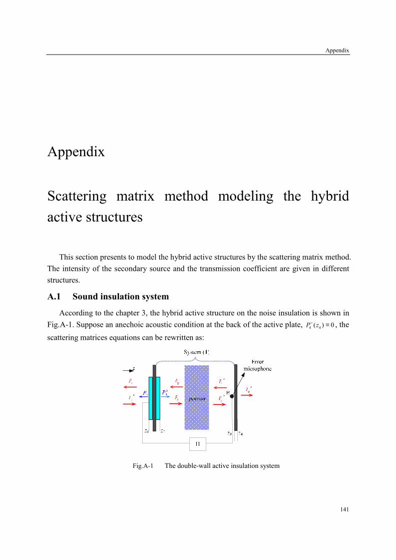
Appendix
141
Appendix
Scattering matrix method modeling the hybrid
active structures
This section presents to model the hybrid active structures by the scattering matrix method.
The intensity of the secondary source and the transmission coefficient are given in different
structures.
A.1 Sound insulation system
According to the chapter 3, the hybrid active structure on the noise insulation is shown in
Fig.A-1. Suppose an anechoic acoustic condition at the back of the active plate, 4 4
( ) 0P z− = , the
scattering matrices equations can be rewritten as:
Fig.A-1 The double-wall active insulation system
Appendix
142
11 1 1 1
22 2 2 2
( )( ) ( )
( )( ) ( )
S
S
P zP z P z
P zP z P z
−− +
++ −
= ⋅ +
SD (A-1)
2 2 2 2
3 3 3 3
( ) ( )
( ) ( )
P z P z
P z P z
− +
+ −
= ⋅
1D (A-2)
3 3 3 3
4 4
( ) ( )
( ) 0
P z P z
P z
− +
+
= ⋅
PD (A-3)
Here, 1D is the scattering matrix of the system (1) located between axial coordinates 1z and 2z ;
PD is the scattering matrix of the elastic thin plate located between axial coordinates 3z and 4z ;
SD is the scattering matrix of the active plate; The vector 1 2
( ) ( )T
S SP z P z− + is the radiating
pressure of the active plate; The other pressure vectors in each equation respectively are the
incoming and outgoing waves of each systems.
From Eq. (A-1) ~ (A-3), we can calculate3 3( )P z as well as the reflected and transmitted
pressures 1 1
( )P z− and 4 4
( )P z+ at the emission and the transmission side based on the symmetry
of the active plate, respectively:
3 3 1 1 1 2 2( ) ( ) ( )
SP z b P z b P z+ += + (A-4)
1 1 3 1 1 4 2( ) ( ) ( )SP z b P z b P z− + += + (A-5)
4 4 5 1 1 6 2( ) ( ) ( )SP z b P z b P z+ + += + (A-6)
Here,
1
211 1
22 111P
DC
D D=
− 1 1
1 11 12 11 1
PE D D D C= + 212
22 11
S
S
DC
D E=
− 2
22 1
1
1S
ED E
=−
1 1 2 11( 1)Pb C C D= +
2 1 2 11( 1)Pb C E D= +
3 11 12 1 2
S Sb D D E C= +
4 12 1 21Sb D E E= +
5 21 1 2
Pb D C C= 6 21 1 2
Pb D C E=
1
ijD , P
ijD , S
ijD , , 1, 2i j = , are the elements of the scattering matrices 1D , PD , SD . These
scattering matrices are deduced from analytical transfer matrices associated respectively to the
system (1), the elastic thin plate and the active plate (Chapter 2).
In active control, the pressure 3
P vanishes, thus
1
3 3 2 1 1
2
( ) 0 ( ) ( )S
bP z P z P z
b
+ += ⇒ = − (A-7)
With the factor χ for describing the active control degree, its expression as follows:

Appendix
143
1
2 1 1
2
( ) ( )S
bP z P z
bχ+ += − ⋅ (A-8)
The reflection and transmission coefficients at 1
z and4
z , respectively, are determined from
Eq. (A-5) ~ (A-8):
1 41 1 1 1 3
2
( ) ( ) ( )b b
R P z P z bb
χ χ− + = = − ⋅
(A-9)
1 6
4 4 1 1 5
2
( ) ( ) ( )b b
P z P z bb
τ χ χ+ + = = − ⋅
(A-10)
A.2 Hybrid systems
A.2.1 Active control with one error sensor based on sound insulation
According to the chapter 3, the hybrid active structure on the noise insulation with one
error sensor is shown in Fig.A-2. Suppose an anechoic acoustic condition at the back of the
active plate, the scattering matrices equations can be rewritten as:
Fig.A-2 General configuration of the multilayer hybrid active acoustic structures
1 1 1 1
2 2 2 2
( ) ( )
( ) ( )
P z P z
P z P z
− +
+ −
= ⋅
1D (A-11)
2 2 2 2 2
3 3 3 3 3
( ) ( ) ( )
( ) ( ) ( )
S
S
P z P z P z
P z P z P z
− + −
+ − +
= ⋅ +
SD (A-12)
3 3 3 3
4 4 4 4
( ) ( )
( ) ( )
P z P z
P z P z
− +
+ −
= ⋅
2D (A-13)

Appendix
144
4 4 4 4
5 5
( ) ( )
( ) 0
P z P z
P z
− +
+
= ⋅
PD (A-14)
Here, 1D is the scattering matrix of the system (1) located between axial coordinates 1z and 2z ;
2D is the scattering matrix of the system (2) located between axial coordinates 2z and 3z ; SD
is the scattering matrix of the active plate; PD is the scattering matrix of the elastic thin plate;
From Eq. (A-11) ~ (A-14), we can calculate4 4
( )P z as well as the reflected and transmitted
pressures 1 1
( )P z− and 5 5
( )P z+ at the emission and the transmission side based on the symmetry
of the active plate, respectively:
4 4 1 1 1 2 3( ) ( ) ( )SP z g P z g P z+ += + (A-15)
1 1 3 1 1 4 3( ) ( ) ( )SP z g P z g P z− + += + (A-16)
5 5 5 1 1 6 3( ) ( ) ( )SP z g P z g P z+ + += + (A-17)
Here,
2
211 2
22 111P
DF
D D=
− 2 2
1 11 12 11 1
PG D D D F= + 212
22 11
S
S
DF
D G=
− 2
22 1
1
1S
GD G
=−
3 11 12 1 2
S SF D D G F= + 3 12 1 2
SG D G G= 1
211 1
22 31
Dd
D F=
−
1
22 3
2 1
22 31
D Gd
D F=
−
1
223 1
22 31
Dd
D F=
−
1 1 2 1 11( 1)Pg F F d D= +
2 1 2 2 1 2 1 2 3 11( )( 1)Pg F F d F G F F d D= + + +
1 1
3 11 12 3 1g D D F d= + 1
4 12 3 2 3 3 3( 1)g D F d G F d= + + +
5 21 1 2 1
Pg D F F d= 6 21 1 2 2 1 2 1 2 3
( )Pg D F F d F G F F d= + +
1
ijD , 2
ijD , P
ijD , S
ijD , , 1, 2i j = , are the elements of the scattering matrices 1D , 2D , PD , SD . These
scattering matrices are deduced from analytical transfer matrices associated respectively to the
system (1), the system (2), the elastic thin plate and the active plate (Chapter 2).
In active control, 3
( )S
P z+ which cancel the pressure at 4z is:
1
4 4 3 1 1
2
( ) 0 ( ) ( )S
gP z P z P z
g
+ += ⇒ = − (A-18)
Considering the factor χ for describing the active control degree, its expression can be
rewritten as follows:
1
3 1 1
2
( ) ( )S
gP z P z
gχ+ += − ⋅ (A-19)

Appendix
145
Reflection and transmission coefficients at 1
z and5
z are determined respectively:
1 41 1 1 1 3
2
( ) ( ) ( )g g
R P z P z gg
χ χ− + = = − ⋅
(A-20)
1 6
5 5 1 1 5
2
( ) ( ) ( )g g
P z P z gg
τ χ χ+ + = = − ⋅
(A-21)
A.2.2 Active control with one error sensors based on sound absorption
Another hybrid active acoustic structure with one error senor in active control is shown in
Fig.A-3, in which the error sensor (point A) makes the system (1) as an equivalent of the λ/4
resonance absorber. In this case, the system (1) is divided into two parts: the scattering matrix
written by 1aD in the range of 1 1z z z′< < and 1bD in the range of 1 2z z z′ < < .
1 1 1 1 2 1 2 1
2 1 2 1 2 2 2 2
( ) ( ) ( ) ( ),
( ) ( ) ( ) ( )
P z P z P z P z
P z P z P z P z
− + − +
+ − + −
′ ′ = ⋅ = ⋅ ′ ′
1a 1bD D (A-22)
1Z ′
Fig.A-3 The hybrid system in active control with two error sensor
The scattering matrices of the active plate, the system (2) and the elastic thin plate are
expressed by Eq. (A-12) ~ (A-14), in the case of anechoic upstream acoustic conditions
( )5 5( ) 0P z− = .
Because of the symmetrical geometry and material proprieties of the used active plate, we
calculate the pressure 2 1( )P z′ ,
4 4( )P z as well as the reflected and transmitted pressures
1 1( )P z−
and 5 5
( )P z+ at the emission and the transmission side, respectively:
2 1 1 1 1 2 3( ) ( ) ( )SP z e P z e P z+ +′ = + (A-23)
4 4 3 1 1 4 3( ) ( ) ( )SP z e P z e P z+ += + (A-24)
Appendix
146
1 1 5 1 1 6 3( ) ( ) ( )SP z e P z e P z− + += + (A-25)
5 5 7 1 1 8 3( ) ( ) ( )SP z e P z e P z+ + += + (A-26)
Here,
1
211 1
22 31
b
b
Dm
D F=
−
1
22 3
2 1
22 31
b
b
D Gm
D F=
−
1
223 1
22 31
b
b
Dm
D F=
−
1 1
1 11 12 3 1
b bn D D F m= + 1
2 12 3 2 3( )bn D F m G= + 1
3 12 3 3( 1)bn D F m= +
1
211 1
22 11
a
a
Dq
D n=
−
1
22 22 1
22 11
a
a
D nq
D n=
−
1
22 3
2 1
22 11
a
a
D nq
D n=
−
1 1 1 1e n q q= +
2 1 2 3 2 3( 1)( )e n q q n n= + + + +
3 11 1 2 1 1( 1)Pe D F F m q= +
4 1 2 1 2 2 2 2 2 1 3 2 3 11( )( 1)Pe F F m q F m G F m q F m D= + + + + + 1 1
5 11 12 1 1
a ae D D n q= +
1
6 12 1 2 2 1 3 3( )ae D n q n n q n= + + +
7 21 1 2 1 1
Pe D F F m q=
8 21 1 2 1 2 2 2 2 2 1 3 2 3( )Pe D F F m q F m G F m q F m= + + + +
The parametersi
F , i
G , , 1, 2,3i j = are defined in the section C.1. 1a
ijD , 1b
ijD , 2
ijD , P
ijD , S
ijD , , 1, 2i j = ,
are the elements of the scattering matrices 1aD , 1bD , 2D , PD , SD .
In active control, 3
( )S
P z+ which cancel the pressure at z′ is:
1
2 1 3 1 1
2
( ) 0 ( ) ( )S
eP z P z P z
e
+ +′ = ⇒ = − (A-27)
Considering the factor χ for describing the active control degree, its expression can be
rewritten as follows:
1
3 1 1
2
( ) ( )S
eP z P z
eχ+ += − ⋅ (A-28)
Reflection and transmission coefficients at 1
z and5
z , respectively, are determined from Eq.
(3-28), (3-25) and (3-26):
1 6
1 1 1 1 5
2
( ) ( ) ( )e e
R P z P z ee
χ χ− + = = − ⋅
(A-29)
1 8
5 5 1 1 7
2
( ) ( ) ( )e e
P z P z ee
τ χ χ+ + = = − ⋅
(A-30)
A.2.3 Active control with two error sensors

Appendix
147
A hybrid active acoustic structure with two error senor in active control is shown in
Fig.A-4, in which the combination of the active cells in the section A.2.1 and A.2.2 makes the
system (1) as an equivalent of the λ/4 resonance absorber and the system (2) as a sound
insulation system.
1Z ′
Fig.A-4 The hybrid system in active control with two error sensors
To simulate the active control of the error sensors located at1
z′ , 4
z (point A and B), the
pressure radiated by the active plate in the both sides must be introduced in computations in
order to minimize the acoustic power. Therefore, the control objective is written as:
2 2 * *
2 1 4 4 2 1 2 1 4 4 4 4( ) ( ) ( ) ( ) ( ) ( )J P z P z P z P z P z P z′ ′ ′= + = + (A-31)
Suppose 1
1 1 1( )j
P z P eϕ+ += , 3( ) sj
S SP z P eϕ+ += , the control objective is rewritten as:
1 1* *
1 1 2 1 1 2( )( )s sj jj j
S SJ e P e e P e e P e e P eϕ ϕϕ ϕ −−+ + + += + + 1 1* *
3 1 4 3 1 4( )( )s sj jj j
S Se P e e P e e P e e P eϕ ϕϕ ϕ −−+ + + ++ + +
2
S Sa P b P c+ += + + (A-32)
Here, 2 2
2 4a e e= + , * * * *
1 2 3 4 1 2 1 4 3 1( ) ( )j j
b e e e e P e e e e e P eϕ ϕ+ ∆ + − ∆= + + + , ( ) 22 2
1 3 1c e e P
+= + , 1 s
ϕ ϕ ϕ∆ = − .
To make the control objective equal to minimum S
P+ should satisfy the condition with the
phase s
ϕ fixed:
3( )
2sj
S
bP z e
a
ϕ+ = − (A-33)
Considering the factor χ of the active control degree, Eq. (A-33) submits to:

Appendix
148
3( )
2sj
S
bP z e
a
ϕχ+ = − ⋅ (A-34)
Reflection and transmission coefficients at 1
z and5
z , respectively, are determined from
Eqs. (A-34), (A-25) and (A-26):
61 1 1 1 5
1
( ) ( ) ( )2
jbeR P z P z e e
a P
ϕχ χ− + − ∆+
= = − ⋅
(A-35)
85 5 1 1 7
1
( ) ( ) ( )2
jbeP z P z e e
a P
ϕτ χ χ+ + − ∆+
= = − ⋅
(A-36)
Bibliography
149
Bibliography
1. Kean Chen. Active Noise Control, chap. 1 in Traditional noise control approaches and
its characteristics, National Defense Industry Press, Beijing, China, (2003).
2. P.A. Nelson, S.J. Elliott, Active control of sound, Academic Press, London, (1992).
3. C.R. Fuller, S.J. Elliott, P.A. Nelson, Active control of vibration, Academic Press, San
Diego, (1996).
4. X.F. Yin, Kean Chen. Active acoustic structure: concept, realization and application,
J. Vib. Eng., 16(3), 261-268, (2003).
5. P. Leug. Process of silencing sound oscillations, German patent DRP No. 655508,
(1933).
6. P. Leug. Process of silencing sound oscillations, US patent No.2043416, (1936).
7. H.F. Olson, E.G. May. Electronic sound absorber, J. Acoust. Soc. Am., 25, 1130-1136,
(1953).
8. L.J. Eriksson. A brief social history of active sound control, Sound and Vibration, 33(7),
14-17, (1999).
9. Kean Chen, Y.L. Ma. Adaptive active noise control- theory, arithmetic and realization,
Northwestern Polytechnique Univsrsity Press, Xi’an, (1993).
10. C.H. Hansen. Active noise control: from laboratory to industrial implementation,
Proceedings of NOISE-CON 97, State College, Pennsylvania, 3-39,(1997).
11. L.J. Eriksson, M.C. Allie. A practical system for active attenuation in ducts, Sound and
Vibration, 22, 30-34, (1988).
Bibliography
150
12. H.S. Kim, J.S. Hong, D.G. Sohn, et al. Development of an active muffler system for
reducing exhaust noise and flow restriction in a heavy vehicles, Noise Control
Engineering Journal, 47(2), 57-63, (1999).
13. J.G. Casali, G.S. Robinson. Narrow band digital active noise reduction in a siren-
canceling headset: real-ear and acoustical manikin insertion loss, Noise Control
Engineering Journal, 42(3), 101-115, (1994).
14. J. Zeta, A.J. Brammer, G.J. Pan. Comparison between subjective and objective measures
of active hearing protector and communication headset attenuation, J Acoust Soc Am.,
101 (6): 3486-3497, (1997).
15. E.G. Goodfellow. A prototype active noise reduction in-ear heating protector, Applied
Acoustics, 42, 299-312, (1994).
16. J.G. Bonito, S.J. Elliont, C.C. Boucher. Generation of zones of quiet using a virtual
microphone arrangement, J Acoust Soc Am., 101, 3498-3516, (1997).
17. H.V. Auweraer, D. Otte, G. Venet., et al. Aircraft interior sound field analysis in view of
active control: Results from the ASANCA project, Proceedings of Noise-Con’93, 219-
224, (1993)
18. C.M. Dorling. A demonstration of active noise reduction in an aircraft cabin, J Sound
Vib., 128, 358-360, (1989).
19. S.J. Elliott, P.A. Nelson, I.M. Stothers, et al. Preliminary results of in-flight experiments
on the active control of propeller-induced cabin noise, J Sound Vib., 128, 355-357,
(1989).
20. S.J. Elliott, P.A. Nelson, I.M. Stothers, et al. In-flight experiments on the active control
of propeller-induced cabin noise, J Sound Vib., 140, 219-238, (1990).
21. S.J. Elliott, I.M. Stothers, P.A. Nelson, et al. The active control of engine noise inside
cars, Proceedings of Inter-Noise' 88, 987- 990, (1988).
22. T.J. Sutton, S.J. Elliott, A.M. McDonald, et al. Active control of road noise inside
vehicles, Noise Control Engineering Journal, 42(4), 137- 147, (1994).
23. R.J. Benhard. Active control of road noise inside automobiles, Proceedings of Active'95,
21-32, (1995).
24. C. Deffayet, P.A. Nelson. Active control of low-frequency harmonic sound radiated by a
finite panel, J Acoust Soc Am., 84(6), 2192-2199, (1988)

Bibliography
151
25. C.R. Fuller. Experiments on reduction of aircraft interior noise using of active control of
fuselage vibration, J Acoust Soc Am., 78(S1), S79, (1985).
26. H.C. Lester, C.R. Fuller. Active control of propeller-induced noise fields inside a
flexible cylinder, AIAA Journal, 28, 1374-1380, (1990).
27. M.A. Simpson, T.M. Luong, C.R. Fuller, et al. Full scale demonstration tests of cabin
noise reduction using vibration, AIAA Journal of Aircraft, 28, 208-215, (1991).
28. C.R. Fuller, C.H. Hansen, S D Snyder. Active control of sound radiation from a
vibration rectangular panel by sound sources and vibration inputs: an experimental
comparison, J Sound Vib., 145, 195-215, (1991).
29. C.R. Fuller. Active control of sound transmission/radiation from elastic plates by
vibration inputs, I: Analysis, J Sound Vib., 136(1), 1-15, (1990).
30. J. Pan, S. DSynder, C.H. Hansen, et al. Active control of far-field sound radiated by a
rectangular panel a general analysis, J Acoust Soc Am., 91, 2056-2066, (1992).
31. C.R. Fuller, C.H. Hansen, S.D. Snyder. Experiments on active control of sound radiated
from a panel using piezoelectric actuators, J Sound Vib., 150, 179-190, (1991).
32. B. Wang, C.R. Fuller, E.K. Dimitriadis. Active control of noise transmission through
rectangular plates using multiple piezoelectric or point force actuators, J Acoust Soc
Am., 90(5), 2820-2830, (1991).
33. C. Bao, J. Pan. Experimental study of different approach for active control of sound
transmission through double walls, J Acoust Soc Am., 102, 1662-1670, (1997).
34. B. Wang. Optimal placement of microphone and piezoelectric transducer actuators for
far-field sound radiation control, J Acoust Soc Am., 99(5), 2975-2984, (1996).
35. M. Salikuddin, H.K. Tanna, R.H. Burrin, et al. Application of active noise control to
model propeller noise, J Sound Vib., 137, 9-41, (1990).
36. S.M. Hirsch, J.Q. Sun. An analytical study of interior noise control using segmented
panels, J Sound Vib., 231: 1007-1021, (2000)
37. S.M. Hirsch, N.E. Meyer, M.A. Westervelt, et al. Experimental study of smart
segmented trim panels for aircraft interior noise control, J Sound Vib., 231, 1023-1037,
(2000).
38. Kean Chen, G.H. Koopmann, Theoretical study on active control of sound radiation
based on planar sound sources, Chinese Journal of Acoustics, 22(4), 360-368, (2003).

Bibliography
152
39. C.R. Fuller, C.A. Rogers, H.H. Robertshaw. Control of sound radiation with
active/adaptive structure, J Sound Vib., 157, 19-39, (1992).
40. Kean Chen, H. Nykanen, G.H. Koopmann. Application of EMFi acoustic actuators into
active control of sound radiation, Proceedings of the 4-th European Con. On Noise
Control, Patras, Greece, (2001).
41. R.L. Pierre, G.H. Koopmann, W. Chen. Volume velocity control of sound transmission
through composite panels, J Sound Vib., 210(4), 441-460, (1998).
42. G.P. Gibbs, R.L. Clark, D.E. Cox, et al. Radiation modal expansion: Application to
active structural acoustic control, J Acoust Soc Am., 107(1), 332-339, (2000).
43. C. Guigou, Z. Li, C.R. Fuller. The relationship between volume velocity and far field
radiated pressure of a planar structure, J Sound Vib., 197(2), 252-254, (1996).
44. B. Wang. the PVDF-based wave number domain sensing techniques for active sound
radiation control from a simply supported beam, J Acoust Soc Am., 103(4), 1904-1915,
(1998).
45. G.V. Borgiotti. The determination of the acoustic far field of a radiating body in an
acoustic fluid from boundary measurements, J Acoust Soc Am., 93, 2788-2797, (1993).
46. A. Berry, X. Qiu, C.H. Hansen. Near-field sensing strategies for the active control of the
sound radiated from a plate, J Acoust Soc Am., 106(6), 3394-3406, (1999).
47. A.P. Berkhoff. Sensor scheme design for active structural acoustic control, J Acoust Soc
Am., 108(3), 1037-1045, (2000).
48. E.F. Crawley. Intelligent structures for aerospace: a technology overview and
assessment. AIAA Journal, 32, 1689-1699, (1994).
49. M. Paajanen, H. Valimaki, J. Lekkala. Modelling the electromechanical film (EMFi),
Journal of Electrostatics, 48, 193-204, (2000).
50. R. Heydt, R. Pelrine, J. Joseph, et al. Acoustic performance of an electrostrictive
polymer film, J Acoust Soc Am., 107, 833-839, (2000).
51. T. Samejima. Development of panel loudspeaker system: design, evaluation and
enhancement, J Acoust Soc Am., 109(6), 2751-2761, (2001).
52. I. Berger. Deep thoughts on shallow speaker, Audio Magazine, April 1999
53. H. Nykanen, M. Antila, J. Kataja, et al. Active control of sound based on utilizing EMFi
technology, ACTIVE’99, Fort Lauderdale, Florida, (1999).

Bibliography
153
54. H. Nykanen, R. Aimasso, D. Bondoux, et al. EMFi based ANC systems in transporation
system, FACTS Report PR.7.1, (2000).
55. DAFNOR. Distributed Active Foils for Noise Reduction, Final Technical Report, Brite-
EuRam project No. BE97Ⅲ -4970.
56. FACTS. Film Actuators and Active Control of Sound for Comfort in Tranportation
System, Brite-EuRam project No.BE95Ⅲ -1578.
57. SMARTCUS. Smart Acoustics House, Brite-EuRam project NoⅢ . BE97-4970.
58. Kean Chen, G.H. Koopmann. Active control of low-frequency sound radiation from
vibrating panel using planar sound sources, ASME, J Sound Vib., 124(1), 2-9, (2002).
59. Kean Chen, G.H. Koopmann. Active enhancement of low frequency sound transmission
loss using planar sound sources, Proceedings of the ASME International Mechanical
Engineering Congress & Exposition, Orlando, Florida, Dec., (2000).
60. Kean Chen. Generalized Engineering Analysis of Active Surface of Sound Absorption,
Journal of Northwestern Polytechnique University, 17(2), 181-186, (1999).
61. Kean Chen. The mechanism of active sound absorption unit, J Vib Eng., 11(4), 402-409,
(1998).
62. Kean Chen. Design strategy and Algorithm for adaptive control of active sound
absorption, Journal of Northwestern Polytechnique University, 17(3), 382-386, (1999).
63. Kean Chen, G.H. Koopmann. Theoretical study on active control of sound radiation
based on planar sound sources, Chinese Journal of Acoustics, 2003, 28 (4), 279-293
64. Kean Chen, W.B.Zhong, X.Y. Zeng. the acoustic characteristics of panel loudspeakers,
Audio Engineering, 9, 21-23, (2003).
65. Kean Chen, X.F. Yin. Active control of radiated sound using near field pressure sensing,
Chinese Journal of Acoustics, 23(3), 193-202, (2004).
66. Kean Chen. Error Sensing Strategies for Adaptive Acoustic Structures, J Vib Eng.,
17(3), 301-305, (2004).
67. W.B. Zhong, Kean Chen, H.W. Li. Experimental study of flat panel loudspeakers
applied to active noise control, Appl Acoust, 25(4), 246-251, (2006).
68. H.R. Pan. Optimum configuration design for active acoustic structure, thesis of Master,
Northwestern Polytechnique University, (2006).
69. X.F. Yin. An adaptive combined inverse algorithm applied to multi-channel active
control system, Ph.D thesis, Northwestern Polytechnique University, (2005).
Bibliography
154
70. C.A. Gentry, C. Guigou, C.R. Fuller. Smart foam for applications in passive/active noise
radiation control, J Acoust Soc Am., 101(4):1771-1778, (1997).
71. D.J. Rossetti, M.A. Norris. A comparison of actuation and sensing techniques for
aircraft cabin noise control, Noise Control Engineering Journal, 44(1):53-58, (1996).
72. C.K. Lee. Theory of laminated piezoelectric plates for the design of distributes
sensors/actuators, part I: governing equations and reciprocal relationships. J Acoust Soc
Am., 87, 1144-1158, (1990).
73. E.F. Crawley, J.D. Luis. Use of piezoelectric actuators as elements of intelligent
structures. AIAA Journal, 25, 1373-1385, (1987).
74. N.N. Rogacheva. The Theory of Piezoelectric Shells and Plates. Boca Raton: CRC Press,
(1994).
75. H.S. Tzou. Piezoelectric Shells Distributed Sensing and Control of Continua. Dordrecht:
Kluwer Academic Publishers, (1993).
76. E.H. ANDERSON, N.W. HAGOOD. Simultaneous piezoelectric sensing/actuation:
analysis and application to controlled structures. J Sound Vib., 174, 617-639, (1994).
77. F.P. Mechel, Hybrider Schalldamplfer, Patent No. DE4027511.
78. D. Guicking, E. Lorenz. An active sound absorber with porous plate, J. Vib. Acoust.,
Stress Reliab. Design, 106, 393-396, (1984).
79. D. Thenail, M. Galland, M. Sunyach, M. Sunhack. Active enhancement of the absorbent
properties of a porous material, Smart Mater. Struct, 3, 18-25, (1994).
80. S. Beyene, R.A. Burdisso. A new hybrid passive/active noise absorption system. J
Acoust Soc Am., 101(3), 1512-1515, (1997).
81. M. Furstoss, D. Thenail, M.A. Galland. Surface impedance control for sound absorption:
direct and hybrid passive/active strategies. J Sound Vib., 203(2), 219-236, (1997).
82. O. Lacour, M.A. Galland, D. Thenail. Preliminary experiments on noise reduction in
cavities using active impedance changes. J Sound Vib., 230(1), 69–99, (2000).
83. M.A. Galland, P. Souchotte, P. Ladner, T. Mazoyer. Experimental investigation of noise
reduction in a flow duct through hybrid passive/active liner. In: 7th AIAA/CEAS
aeroacoustics conference, Maastricht, The Netherlands; 28–30 May 2001, 2001–221,
(2001).
Bibliography
155
84. N. Sellen, M. Cuesta, M.A. Galland. Passive layer optimization for active absorbers in
flow duct applications. In: 9th AIAA/CEAS aeroacoustics conference, Hilton Head,
South Carolina. AIAA; 12–14 May 2003, 2003–3186, (2003).
85. M.A Galland, N. Sellen, O. Hilbrunner. Noise reduction in a flow duct by active control
of wall impedance. In: 8th AIAA/CEAS aeroacoustics conference, Breckenridge,
Colorado. AIAA; 17–19 June 2002, 2002–498, (2002).
86. O. Hilbrunner, B. Mazeaud, M.A. Galland. Multi-cell digital feedback control for noise
reduction through hybrid absorbers. In: 9th AIAA/CEAS aeroacoustics conference,
Hilton Head, South Carolina. AIAA; 12–14 May 2003, 2003–3187, (2003).
87. M. A. Galland, B. Mazeaud, N. Sellen. Hybrid passive/active absorbers for flow ducts,
Applied Acoustics, 66, 691-708, (2005).
88. M. Melon, P. Herzog, A. Sitel, M.A. Galland. Etude unidimensionnelle d’une cellule
hybride pour absorption et isolation simultanée, Acoustique Techniques, 60, 46-50,2010.
89. P. Leroy. Les mousses adaptatives pour l’amélioration de l’absorption acoustique :
modélisation, mise en œuvre, mécanismes de contrôle, Thèse de l’Université Aix-
Marseille I, 2008.
90. C. Guigou, C. R. Fuller. Control of aircraft interior broadband noise with foam-pvdf
smart skin, J. Sound Vib., 220, 541-557, (1999).
91. B.D. Johnson, C.R. Fuller. Broadband control of plate radiation using a piezoelectric,
double-amplifier active-skin and structural acoustic sensing, J. Acoust. Soc. Am., 107,
876-884, (2000).
92. J. Pan, C. Bao. Analytical study of different approaches for active control of sound
transmission through double walls. J. Acoust. Soc. Am.,103, 1916-1922, (1998).
93. P.D. Fonseca, P. Sas, H.V. Brussel. Experimental study of the active sound transmission
reduction through a double panel test section. Acustica, 85, 538-46, (1999).
94. P. Sas, C. Bao, F. Augusztinovisz, W. Desmet. Active control of sound transmission
through a double-panel partition. J Sound Vib., 180, 609-25, (1995).
95. F.W. Grosveld, K.P. Shepherd. Active sound-attenuation across a double-wall structure,
J Aircraft 31, 223-227, (1994).
96. J.P. Carneal, C.R. Fuller. Active structural acoustic control of noise transmission
through double panel systems, AIAA, 33, 618-623, (1995).
Bibliography
156
97. C. Bao, J. Pan. Experimental study of different approaches for active control of sound
transmission through double walls, J Acoust Soc Am., 102, 1664-1670, (1997).
98. C.Y. Wang, R. Vaicaitis. Active control of vibrations and noise of double wall
cylindrical shells, J Sound Vib., 216, 865-888, (1998).
99. X. Pan, T.J. Sutton, Elliott SJ. Active control of sound transmission through a double-
leaf partition by volume velocity cancellation, J Acoust Soc Am., 104, 2828-2835,
(1998).
100. P. Gardonio, S.J. Elliott. Active control of structure-borne and airborne sound
transmission through double panel, J Aircraft, 36, 1023-1032, (1998).
101. R. Paurobally, J. Pan, C. Bao. Feedback control of noise transmission through a double-
panel partition, in Proceedings of Active 99, Fort Lauderdale, Florida, USA, 375-386,
(1999).
102. O.E. Kaiser, S.J. Pietrzko, M. Morari. Feedback control of sound transmission through a
double glazed window, J Sound Vib., 263, 775-795, (2003)..
103. A. Jakob, M. Moser. Active control of double-glazed windows Part I: Feedforward
control, Appl Acoust, 64, 163-182, (2003).
104. A. Jakob, M. Moser. Active control of double-glazed windows. Part II: Feedback
control, Appl Acoust, 64, 183-196, (2003).
105. J.P. Carneal, C.R. Fuller. An analytical and experimental investigation of active
structural acoustic control of noise transmission through double panel system, J. Sound
Vib., 272, 749-771, (2004).
106. J. K. Lee, J. Kim, C.J. Rhee, C.H. Jo, and S. B. Choi. Noise reduction of passive and
active hybrid panels, Smart materials and structures, 11, 940-946, (2002).
107. Q. Mao, S. Pietrzko. Control of sound transmission through double wall partitions using
optimally tuned Helmholtz resonators, ACTA Acustica United with Acustica, 91, 723-
731, (2005).
108. S. Pietrzko, Q. Mao. New results in active and passive control of sound transmission
through double wall structures, Aerospace Science and Technology, 12(1), 42-53,
(2008).
109. Q. Mao, S. Pietrzko. Experimental study for control of sound transmission through
double glazed window using optimally tuned Helmholtz resonators, Applied Acoustics,
71(1), 32-38, (2010).
Bibliography
157
110. B. Brouard, D. Lafarge, J.F. Allard, A general method of modeling sound propagation in
layered media, J. Sound Vib., 183(1), 129-142, (1995).
111. M. Fringuellino, C. Guglielmone. Progressive impedance method for the classical
analysis of acoustic transmission loss in multilayered walls, Applied Acoustics, 59, 275-
285, (2000).
112. A. Pellicier, N. Trompette. A review of analytical methods based on the wave approach
to compute partitions transmission loss, Applied Acoustics 68, 1192-1212, (2007).
113. J.S. Lowe. Matrix techniques for modeling ultrasonic waves in multilayered media,
IEEE Transactions on Ultrasonics, Ferroelectrics, and Frequency control, 42(4), 525-
542, (1995).
114. J.S. Sastry, M.L. Munjal. A transfer matrix approach for evaluation of the response of a
multi-layer infinite plate to a two-dimensional pressure excitation, J. Sound Vib., 182(1),
109-128, (1995).
115. M.L. Munjal. Response of a multi-layered infinite plate on an oblique plane wave by
means of transfer matrices, J. Sound Vib., 162, 333-343, (1993).
116. Y.Y. Li, L. Cheng. Mechanisms of active control of sound transmission through a linkes
double-wall system into an acoustic cavity, Applied Acoustics, 69, 614-623, (2008).
117. U. Lee. Vibration analysis of one-dimensional structures using the spectral transfer
matrix method, Engineering Structures, 22, 681-690, (2000).
118. L. Wang, S.I. Rokhlin. Stable reformulation of transfer matrix method for wave
propogation in layered anisotropic media, Ultrasonics, 39, 413-42, (2001).
119. Q.S. Li, K. Yang, L. Zhang, N. Zhang. Frequency domain analysis of fluid-structure
interaction in liquid-filled pipe systems by transfer matrix method, Mechanical Sciences,
44, 2067-2087, (2002).
120. D.H. Lee, Y.P. Kwon. Estimation of the absorption performance of multiple layer
perforated panel systems by transfer matrix method, J. Sound Vib., 278, 847-860,
(2004).
121. H. Liu, J.J. Lee, Z.M. Cai. Analysis of nonlinear acoustoelastic effect of surface acoustic
wave in laminated structures by transfer matrix method, Mechanics Research
Communications, 31, 667-675, (2004).
122. R. Daneshfaraz, B. Kaya. Solution of the propagation of the waves in open channels by
the transfer matrix method, Ocean Engineering, 35, 1075-1079, (2008).
Bibliography
158
123. C.M. Lee, Y. Xu. A modified transfer matrix method for prediction of transmission loss
of multilayer acoustic materials, J. Sound Vib., 326, 290-301, (2009).
124. T.E. Vigran. Sound transmission in multilayered structures - Introducing finite structural
connections in the transfer matrix method, Applied Acoustics, 71, 39-44, (2010).
125. D.H. Lee, S.C. Hur, Y.P. Kwon. Estimation of the sound absorption performance for
multiple layer perforated plate systems by transfer matrix method, Transactions of the
Korean Society for Noise and Vibration Engineering, 12 (9), 709-716, (2002).
126. M. Aböm. Measurement of a scattering-matrix of acoustical two ports, Mechanical
Systems and Signal Processing, 5(2), 89-104, (1991).
127. J. Lavrenjev, H. Bodèn, M. Aböm. A measurement method for determination the source
data of acoustic two-port sources, J. Sound Vib., 197(1), 1-16, (1996).
128. R.Glav, M. Aböm. A general formalism for analyzing acoustic 2-port networks,
J. Sound Vib., 202(5), 739-747, (1997).
129. N. Sellen, O. Hilbrunner, M.A. Galland. Identification of the characteristic parameters
of porous media using active control, 8th AIAA/CEAS Aero acoustics Conference,
AIAA Paper, 2002-2504, (2002).
130. J.F. Allard. Propagation of Sound in Porous Media: Modeling Sound Absorbing
materials, Elsevier, New York, (1993).
131. M.A. Biot, The theory of propagation of elastic waves in a fluid-saturated porous solid,
J Acoust Soc Am., 28, 168-191, (1956).
132. T.W. Geerits, O. Kelder. Acoustic wave propagation through porous media: Theory and
experiments, J Acoust Soc Am., 102(5), 2495-2510, (1997).
133. M. Swift, K. Horoshenkov, P. Leclaire, D. Hotherall, K. Fujiwara, H. Torihama. On the
effect of the bending vibration on the acoustic propertied of thin poroelastic plates, J
Acoust Soc Am., 107, 1786-1789, (2000).
134. N. Dauchez, S. Sahraoui, N. Atalla. Convergence of poroelastic finite elements based on
Biot displacement formulation, J Acoust Soc Am., 109(1), 33-40, (2001).
135. N. Dauchez, S. Sahraoui, N. Atalla. Investigation and moeling of damping in a plate
with a bonded porous layer, J. Sound Vib., 265, 437-449, (2003).
136. J.P. Coyrtte, H. Wynendaele, A finite element model for predicting the acoustical
transmission characteristics of layered structures, In: Proceedings of Inter-noise 95,
1279-1282, (1995).
Bibliography
159
137. Y.J. Kang, J.S. Bolton, Finite element modeling of isotropic elastic porous materials
coupled with acoustical finite elements, J Acoust Soc Am., 98 (1), 635-643, (1995).
138. L. Taber. A theory for transverse deflection of poroelastic plates, J Appl. Mech., 59,
628-634, (1992).
139. D. Theodorakopoulos, D. Beskos. Flexural vibrations of poroelastic plates, Acta
<echanica, 103, 191-203, (1994).
140. P. Leclaire, K. Horoshenkov, A. Cummings. Transverse vibrations of a thin rectangular
porous plate saturated by a fluid, J. Sound Vib., 247, 1-18, (2001).
141. P. Leclaire, K. Horoshenkov, M. Swift, D. Hotherall. The vibrational response of a
clamped rectangular porous plate, J. Sound Vib., 247, 19-31, (2001).
142. R. Panneton, N. Atalla, An efficient finite element scheme for solving the three-
dimensional poroelasticity problem in acoustics, J Acoust Soc Am., 101, 3287-3298,
(1997).
143. N. Atalla, R. Panneton, P. Debergue, A mixed displacement-pressure formulation for
poroelastic materials, J Acoust Soc Am., 104(3), 1444-1452, (1998).
144. P. Debergue, R. Panneton, N. Atalla, Boundary conditions for the weak formulation of
the mixed (u, p) poroelasticity problem, J Acoust Soc Am., 106(5), 2383-2390, (1999).
145. O. Dazel, F. Sgard, An extension of complex modes for the resolution of finite-element
poroelastic problems, J. Sound Vib., 253(2), 421-445, (2002).
146. A. Bermudez, J. L. Ferrin, A. Prieto, Finite element solution of new
displacement/pressure poroelastic models in acoustics, Comput Methods Appl Mech
Engrg. 195, 1914-1932, (2006).
147. C. Batifol, T.G. Zielinski, M.N. Ichchou, M.A. Galland, A finite element study of a
piezoelectric/poroelastic sound package concept, Smart Materials and Structures, 16,
168-177, (2007).
148. C. Batifol, M.N. Ichchou, M.A. Galland. Hybrid modal reduction for poroelastic
materials, Comptes Rendus Mécanique, 336(10), 757-765, (2008).
149. M. Etchessahar, S. Sahraoui, B. Brouard. Bending vibrations of a rectangular poroelastic
plate, C. R. Acad.Sci. Paris, Series II b, 329, 615-620, (2001).
150. M. Etchessahar, S. Sahraoui, B. Brouard. Vibrations of poroelastic plates: Mixed
displacement-pressure modelisation and experiments, Acta Acoustica, 95, 857-865,
(2009).
Bibliography
160
151. ASTM C423-08, Standard test method for sound absorption and sound absorption
coefficients by the reverberation room method.
152. ISO 10534, Determination of sound absorption coefficient and impedance in impedance
tubes.
153. D. Apfel, T. Guenther, J.S. Bolton, J. Pope. Development of a New Sound Transmission
Test for Automotive Sealant Materials, SAE Trans, 106, 2651-2658, (1997).
154. ASTM Standard E 1050-90,Impedance and absorption of acoustical materials using a
tube, two micro-phones, and a digital frequency analysis system.
155. B.H. Song, J.S. Bolton. A transfer-matrix approach for estimating the characteristic
impedance and wave numbers of limp and rigid porous materials, J Acoust Soc Am.,
107(3), 1131-1152, (2000).
156. B.L. Zhu, X.H. Luo. The measurement method of insulation in standing wave tube,
Noise and Vibration Control, 6, 41-43, (2000).
157. Q. Bo, B.L. Zhu. Four-microphone method of sound transmission in the standing wave
tube, Noise and Vibration Control, 6, 44-46, (2002).
158. D.L. Peng, P. Hu, B.L. Zhu. The Modified Computation of the Complex Transmission
Coefficient of Acoustical Panel-in Standing Wave Tube, Journal of Shanghai Jiaotong
University, 41(4), 649-653, (2007).
159. Z. Tao, A.F. Seybert. A review of current techniques for measuring muffler transmission
loss. SAE Paper 03NVC-38, Warrendale, USA: SAE Int, (2001).
160. M.L. Munjal. Acoustics of ducts and mufflers. New York: Wiley-interscience, (1987).
161. M.L. Munjal, A.G. Doige. Theory of a two source-location method for direct
experimental evaluation of the four-pole parameters of an aeroacoustic element. J.
Sound. Vib., 142(2), 323-333, (1990).
162. N. Sellen. Modification de l’impédance de surface d’un matériau par contrôle actif (in
French). Ph.D. dissertation, Ecole Centrale de Lyon, France, (2003).
163. D.J. Johnson, Theory of dynamic permeability and tortuosity in fluid-saturated porous
media, J. Fluid. Mech., 176, 379-402, (1987).
164. Y. Champoux, J. F. Allard. Dynamic tortuosity and bulk modulus in air-saturated porous
media, J. Appl. Phy., 70(4), 1975-1979, (1991).
165. A.F. Seybert, D.F. Ross. Experimental determination of acoustic properties using a two-
microphone randam excitation technique, J. Acoust. Soc. Am., 61, 1362-1370, (1977).

Bibliography
161
166. J.Y. Chung, D.A. Blaser. Transfer function method of measuring in-duct acoustic
properties, I: theory, J. Acoust. Soc. Am., 68, 907-913, (1980).
167. J.Y. Chung, D.A. Blaser. Transfer function method of measuring in-duct acoustic
properties, II: experiment, J. Acoust. Soc. Am., 68, 914-921, (1980).
168. A.F. Seybert. Two-sensor method for the measurement of sound intensity and acoustic
propertied in ducts, J. Acoust. Soc. Am., 83, 2233-2239, (1988).
169. H.J. Wu, W.K. Jiang, L.J. Li. Analysis of the tolerance of sound transmission loss
measured by four-microphone in standing wave tube (in Chinese), Journal of Shanghai
Jiaotong University, 42(8), 1265-1268, (2008).


Publications
163
Publications
Ying Hu, A. Sitel, M.A. Galland, Kean Chen. A plane wave study for improving acoustic
performance of double wall systems using an active-passive method. Noise Control Eng. J.,
2009; 57(3): 193-202. (SCI: 000277302100004; EI: 201009 12735247)
Ying Hu, Kean Chen, M.A. Galland. Experimental study on acoustic performance of double-
wall active sound packages based on two source-location method, Journal of Vibration
Engineering, 32(4): 462-468, 2010.
Ying Hu, Kean Chen, M.A. Galland. Sound transmission of double-wall active sound
package with porous materials based on (u, p) formulation, accepted by Chinese ACTA
ACUSTICA, 2010.
Ying Hu, M.A Galland. Multi-cell hybrid sound packages concepts for improving sound
absorption and insulation. 10eme Congres Français d’Acoustique, 12-26 Avril 2010, Lyon,
France.
Ying Hu, A. Sitel, M.A Galland, Kean Chen. Hybrid sandwiches panels for reducing the
sound reflection and transmission. Inter-noise 2008, 26-29 October, Shanghai, China.
A.Sitel, Ying Hu, M.A.Galland. Active multilayered panels based on porous materials for
improving acoustic performance. Symposium on the Acoustics of Poro-Elastic Materials, 17-
19 December, Bradford, UK, 2008.
A. Sitel, Ying Hu, M.A.Galland. Active-passive multilayered panels for reduction of both
acoustic reflection and transmission. J. Acoust. Soc. Amer., 2008; 123(5): 3874.
A.Sitel, Ying Hu, M.A.Galland. Active-passive multilayered panels for reduction of both
acoustic reflection and transmission. Proceedings of the Acoustics 2008 International
Conference, 29 June - 4 July, Paris, France.
Ying Hu, Kean Chen. A FE-SEA hybrid method for vibration analysis of complex structures,
Journals of Vibration and Shock, 2008; 27(7): 88-94.
Ying Hu, Kean Chen, Kai Pan. Optimization design about plane cabin noise based on
statistical energy analysis, Noise and vibration Control, 2007; 27(2): 65-68.
S. Li, Kean Chen, S.L. Zhao, Ying Hu. Experimental study on active control of sound

Publications
164
radiation based on planar sound sources. Applied Acoustic of China, 2008; 27(5): 363-373.