Embed Size (px)
DESCRIPTION
Actual analysis of a water lithium bromide water absorption system
Citation preview

THERMODYNAMIC ANALYSIS OF WATER LITHIUM BROMIDE VAPOUR ABSORPTION
REFRIGERATION SYSTEM
Submitted to Dr. T. P. Ashok Babu NITK SURATHKAL
SUBMITTED BY
VIKRAMADITYA GAONKAR-10M264
DEPARTMENT OF MECHANICAL ENGINEERING NATIONAL INSTITUTE OF TECHNOLOGY KARNATAKA, SURATHKAL,
MANGALORE -575025

1. Abstract
Lithium bromide-water absorption cooling technologies is underpinned by the continual circulation of water, which is the refrigerant, powered by the hygroscopic nature of aqueous lithium bromide solution. The present energy and global warming crises engender a renewed interest in thermally driven cooling systems, for which lithium bromide-water absorption chiller is an archetypal example forming the focus of this report. he internal operation of a lithium bromide-water absorption chiller is intimately influenced by the pressures and concentrations of its working fluid. In its most basic form, there are four intrinsic components to a lithium bromide-water absorption chiller: an evaporator, a generator, an absorber and a condenser.
2. Introduction
The first absorption chiller was developed by Edmond Carré in 1850 using water and sulphuric acid. His brother Ferdinand Carré patented a commercial ammonia-water refrigerator in 1873. However absorption chillers have only started to enjoy serious deployment since the late 1960s when the standard single-effect LiBr-H2O absorption cycle was used. In 1970, Trane introduced the first mass produced double-effect LiBr-H2O absorption chiller [1]. Ever since then LiBr-H2O absorption chillers became an effective means to harness thermal energy. In the early years of the twentieth century, the vapor absorption cycle using water-ammonia systems was popular and widely used. After the development of the vapor compression cycle, the vapor absorption cycle lost much of its importance because of its low coefficient of performance (about one fifth of that of the vapor compression cycle). Today, the vapor absorption cycle is used mainly where fuel for heating is available but electricity is not, such as in recreational vehicles that carry LP gas. It is also used in industrial environments where plentiful waste heat overcomes its inefficiency.
The absorption cycle is similar to the compression cycle, except for the method of raising the pressure of the refrigerant vapor. In the absorption system, the compressor is replaced by an absorber which dissolves the refrigerant in a suitable liquid, a liquid pump which raises the pressure and a generator which, on heat addition, drives off the refrigerant vapor from the high-pressure liquid. Some work is needed by the liquid pump but, for a given quantity of refrigerant, it is much smaller than needed by the compressor in the vapor compression cycle. In an absorption refrigerator, a suitable combination of refrigerant and absorbent is used. The most common combinations are ammonia (refrigerant) with water (absorbent), and water (refrigerant) with lithium bromide (absorbent).
Vapour absorption refrigeration systems using water-lithium bromide pair are extensively used in large capacity air conditioning systems. Since water is used as refrigerant, using these systems it is not possible to provide refrigeration at sub-zero temperatures. Hence it is used only in applications requiring refrigeration at temperatures above 0oC. Hence these systems are used for air conditioning applications. Water is used as the refrigerant while lithium bromide (Li Br) is used as the absorbent. In the absorber, the lithium bromide absorbs the water refrigerant, creating

a solution of water and lithium bromide. This solution is pumped by the pump to the generator where the solution is heated. The water refrigerant gets vaporized and moves to the condenser where it is cooled while the lithium bromide flows back to the absorber where it further absorbs water coming from the evaporator. The analysis of this system is relatively easy as the vapour generated in the generator is almost pure refrigerant (water), unlike ammonia-water systems where both ammonia and water vapour are generated in the generator.
3. Properties of Water‐Lithium Bromide Solution
3.1 Salient features of the Water-Lithium Bromide Solution
1) Lithium bromide has great affinity for water vapor, however, when the water-lithium bromide solution is formed, they are not completely soluble with each other under all the operating conditions of the absorption refrigeration system. Because of this, the designer must take care that such conditions would not be created where crystallization and precipitation of the lithium bromide would occur. 2) The water used as the refrigerant in the absorption refrigeration system means the operating pressures in the condenser and the evaporator must be very low. Even the difference of pressure between the condenser and the evaporator are very low, and this can be achieved even without installing the expansion valve in the system, since the drop in pressure occurs due to friction in the refrigeration piping and also in the spray nozzles. 3) The capacity of any absorption refrigeration system depends on the ability of the absorbent to absorb the refrigerant, which in turn depends on the concentration of the absorbent. To increase the capacity of the system, the concentration of absorbent should be increased, which would enable absorption of more refrigerant. Some of the most common methods used to change the concentration of the absorbent are: controlling the flow of the steam or hot water to the generator, controlling the flow of water used for condensing in the condenser, and re-concentrating the absorbent leaving the generator and entering the absorber.
3.2 Composition
The composition of water-lithium bromide solutions can be expressed either in mass fraction (ξ) or mole fraction (x). For water-lithium bromide solutions, the mass fraction ξ is defined as the ratio of mass of anhydrous lithium bromide to the total mass of solution, i.e.
ξm
m m
where m andm are the mass of anhydrous lithium bromide and water in solution,
respectively. The composition can also be expressed in terms of mole fraction of lithium bromide as:
xn
n n
where n andn are the number of moles of anhydrous lithium bromide and water in solution, respectively. The number moles of lithium bromide and water can easily be obtained from their respective masses in solution and molecular weights, thus:
nmM
andnmM
where ML 86.8kg/kmol) and MW 18.0kg/kmol are the molecular weights of anhydrous lithium bromide and water respectively.
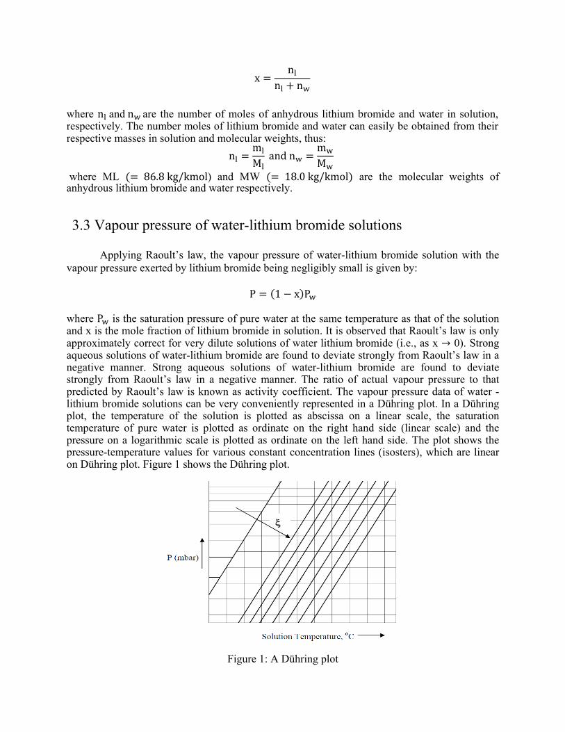
3.3 Vapour pressure of water-lithium bromide solutions
Applying Raoult’s law, the vapour pressure of water-lithium bromide solution with the vapour pressure exerted by lithium bromide being negligibly small is given by:
P 1 x P
where P is the saturation pressure of pure water at the same temperature as that of the solution and x is the mole fraction of lithium bromide in solution. It is observed that Raoult’s law is only approximately correct for very dilute solutions of water lithium bromide (i.e., as x → 0). Strong aqueous solutions of water-lithium bromide are found to deviate strongly from Raoult’s law in a negative manner. Strong aqueous solutions of water-lithium bromide are found to deviate strongly from Raoult’s law in a negative manner. The ratio of actual vapour pressure to that predicted by Raoult’s law is known as activity coefficient. The vapour pressure data of water -lithium bromide solutions can be very conveniently represented in a Dühring plot. In a Dühring plot, the temperature of the solution is plotted as abscissa on a linear scale, the saturation temperature of pure water is plotted as ordinate on the right hand side (linear scale) and the pressure on a logarithmic scale is plotted as ordinate on the left hand side. The plot shows the pressure-temperature values for various constant concentration lines (isosters), which are linear on Dühring plot. Figure 1 shows the Dühring plot.
Figure 1: A Dühring plot

Figure 2: The water LiBr system [1]
The Dühring plot can be used for finding the vapour pressure data and also for plotting the operating cycle. Figure 2 shows the water-lithium bromide based absorption refrigeration system on Dühring plot. Other types of charts showing vapour pressure data for water-lithium bromide systems are also available in literature.
3.4 Enthalpy of water-lithium bromide solutions
Since strong water-lithium bromide solution deviates from ideal solution behavior, it
is observed that when water and anhydrous lithium bromide at same temperature are mixed adiabatically, the temperature of the solution increases considerably. This indicates that the mixing is an exothermic process with a negative heat of mixing. Hence the specific enthalpy of the solution is given by:
h ξ. h 1 ξ h ∆h
where h andh are the specific enthalpies of pure lithium bromide and water, respectively at the same temperature. Figure 3 shows a chart giving the specific enthalpy-temperature-mass fraction data for water-lithium bromide solutions. The chart is drawn by taking reference enthalpy of 0kJ/kg for liquid water at 0oC and solid anhydrous lithium bromide salt at 25oC.

The enthalpy of pure water vapour and liquid at different temperatures and pressures can be obtained from pure water property data. For all practical purposes, liquid water enthalpy, h , at any temperature T can be obtained from the equation:
h , 4.19 T T kJ/kg where T is the reference temperature, 0oC.
Figure 3: Enthalpy –Temperature - Concentration diagram for H2O-LiBr solution
3.5 Enthalpy values for pure water (liquid and superheated vapour)
The enthalpy of pure water vapour and liquid at different temperatures and pressures can be obtained from pure water property data. For all practical purposes, liquid water enthalpy, h , at any temperature T can be obtained from the equation:
h , 4.19 T T kJ/kg where T is the reference temperature, 0oC.
The water vapour generated in the generator of water-lithium bromide system is in super-heated condition as the generator temperature is much higher than the saturation water

temperature at that pressure. The enthalpy of superheated water vapour, h , at low pressures and temperature T can be obtained approximately by the equation:
h , 2501 1.88 T T kJ/kg
3.6 Crystallization
The pressure-temperature-mass fraction and enthalpy-temperature -mass fraction charts show lines marked as crystallization in the lower right section. The region to the right and below these crystallization lines indicates solidification of LiBr salt. In the crystallization region a two-phase mixture (slush) of water-lithium bromide solution and crystals of pure LiBr exist in equilibrium. The water-lithium bromide system should operate away from the crystallization region as the formation of solid crystals can block the pipes and valves. Crystallization can occur when the hot solution rich in LiBr salt is cooled in the solution heat exchanger to low temperatures. To avoid this, the condenser pressure reduction below a certain value due to say, low cooling water temperature in the condenser should be avoided. Hence in commercial systems, the condenser pressure is artificially maintained high even though the temperature of the available heat sink is low. This actually reduces the performance of the system, but is necessary for proper operation of the system. It should be noted from the property charts that the entire water-lithium bromide system operates under vacuum.
4. Steady flow analysis of Water‐Lithium Bromide Systems
Figure 4: A schematic of water LiBr system; A Absorber; C Condenser; G Generator; P
Solution Pump; SHX Solution HX; ER Refrigerant Expansion valve; ES Solution Expansion Valve

Figure 4 shows the schematic of the system indicating various state points. A steady flow analysis of the system is carried out with the following assumptions: i. Steady state and steady flow ii. Changes in potential and kinetic energies across each component are negligible iii. No pressure drops due to friction iv. Only pure refrigerant boils in the generator.
The nomenclature followed is: m = mass flow rate of refrigerant, kg/s m = mass flow rate of strong solution (rich in LiBr), / m = mass flow rate of weak solution (weak in LiBr), / The circulation ratio (λ) is defined as the ratio of strong solution flow rate to refrigerant flow rate. It is given by:
λmm
implies that the strong solution flow rate is given by:
m λm
The analysis is carried out by applying mass and energy balance across each component. Condenser: m m m
Q m h h
P P T where T is the condenser temperature Expansion valve (refrigerant): m m m
h h

Evaporator:
m m m
Q m h h
P P T where T is the evaporator pressure: Absorber: From total mass
m m m
m λm ⇒m 1 λ m
From mass balance for pure water:
m 1 ξ m 1 ξ m
λξ
ξ ξ
Q mh λmh 1 λ mh
⇒ Q m h h λ h h
The first term in the above equation m h h represents the enthalpy change of water as changes its state from vapour at state 4 to liquid at state 5. The second term mλ h h represents the sensible heat transferred as solution at state 10 is cooled to
solution at state 5. Solution pump:
m m m
W m h h 1 λ m h h
however, if we assume the solution to be incompressible, then:

W 1 λ m P 1 λ m P where is the specific volume of the solution which can be taken to be approximately equal to 0.00055 3/ . Even though the solution pump work is small it is still required in the selection of suitable pump.
4. Practical problems in water‐lithium bromide systems
Practical problems typical to water-lithium bromide systems are:
1. Crystallization 2. Air leakage, and 3. Pressure drops
As mentioned before to prevent crystallization the condenser pressure has to be maintained at
certain level, irrespective of cooling water temperature. This can be done by regulating the flow rate of cooling water to the condenser. Additives are also added in practical systems to inhibit crystallization. Since the entire system operates under vacuum, outside air leaks into the system. Hence an air purging system is used in practical systems. Normally a two -stage ejector type purging system is used to remove air from the system. Since the operating pressures are very small and specific volume of vapour is very high, pressure drops due to friction should be minimized. This is done by using twin- and single-drum arrangements in commercial systems. Few other disadvantages are corrosion due to the reaction of LiBr with the metal tubing which not onyl damages the piping but also makes the solution less effective. [4]
6. Heat sources for water‐lithium bromide systems
Water-lithium bromide systems can be driven using a wide variety of heat sources. Large capacity systems are usually driven by steam or hot water. Small capacity systems are usually driven directly by oil or gas. A typical single effect system requires a heat source at a temperature of about 120oC to produce chilled water at 7oC when the condenser operates at about 46 oC and the absorber operates at about 40oC. The COPs obtained in the range of 0.6 to 0.8 for single effect systems while it can be as high as 1.2 to 1.4 for multi-effect systems.
7. Minimum heat source temperatures for LiBr‐
Water systems
Application data for a single-stage water-lithium bromide vapour absorption system with an output chilled water temperature of 6.7 oC (for air conditioning applications) is shown in Table 1.

Cooling water temperature Minimum Heat source COP (inlet to absorber & temperature
condenser) (Inlet to generator) 23.9 oC 65oC 0.75 26.7 oC 75 oC 0.74 29.4 oC 85 oC 0.72 32.2 oC 95 oC 0.71
Table 1. Application data for a single-stage water-lithium bromide system
The above values are simulated values, which were validated on actual commercial
systems with very efficient heat and mass transfer design. If the heat and mass transfer is not very efficient, then the actual required heat source temperatures will be higher than the reported values. For a given cooling water temperature, if the heat source temperature drops below the minimum temperature given above, then the COP drops significantly. For a given cooling water temperature, if the heat source temperature drops below a certain temperature (minimum generation temperature), then the system will not function. Minimum generation temperature is typically 10 to 15 oC lower than the minimum heat source temperature. If air cooled condensers and absorbers are used, then the required minimum heat source temperatures will be much higher (≈ 150 oC). The COP of the system can be increased significantly by multi-effect (or mult-stage) systems. However, addition of each stage increases the required heat source temperature by approximately 50 oC.
8. Capacity control
Capacity control means capacity reduction depending upon load as the capacity will be maximum without any control. Normally under both full as well as part loads the outlet temperature of chilled water is maintained at a near constant value. The refrigeration capacity is then regulated by either:
1. Regulating the flow rate of weak solution pumped to the generator through the solution pump
2. Reducing the generator temperature by throttling the supply steam, or by reducing the flow rate of hot water
3. Increasing the condenser temperature by bypassing some of the cooling water supplied to the condenser
Method 1 does not affect the COP significantly as the required heat input reduces with
reduction in weak solution flow rate, however, since this may lead to the problem of crystallization, many a time a combination of the above three methods are used in commercial systems to control the capacity.

9. Standard Problem A single stage vapour absorption refrigeration system based on H2O-LiBr has a refrigeration
capacity of 300 kW. The system operates at an evaporator temperature of 5oC (P =8.72 mbar) and a condensing temperature of 50 oC (P =123.3 mbar). The exit temperatures of absorber and generator are 40 oC and 110 oC respectively. The concentration of solution at the exit of absorber and generator are 0.578 and 0.66, respectively. Assume 100 percent effectiveness for the solution heat exchanger, exit condition of refrigerant at evaporator and condenser to be saturated and the condition of the solution at the exit of absorber and generator to be at equilibrium. Enthalpy of strong solution at the inlet to the absorber may be obtained from the equilibrium solution data.
Find: a) The mass flow rates of refrigerant, weak and strong solutions b) Heat transfer rates at the absorber, evaporator, condenser, generator and solution heat exchanger c) Solution pump work (density of solution = 1200 kg/m3). Given:
Refrigeration capacity : 300 kW
Evaporator temperature : 5oC
Condenser temperature : 50oC
Absorber temperature : 40oC
Generator temperature : 110oC
Weak solution concentration, ξWS : 0.578
Strong solution concentration, ξSS : 0.66
Effectiveness of solution HX, εHX : 1.0
Density of solution, ρsol : 1200 kg/m3
Refrigerant exit at evaporator & condenser : Saturated
Solution at the exit of absorber & generator : Equilibrium

Assuming the refrigerant vapour at the exit of generator to be in equilibrium with the strong solution leaving the generator
⇒ Temperature of vapour at generator exit = 110oC
⇒ enthalpy of vapour = 2501+1.88 X 110 = 2708 kJ/kg From the definition of effectiveness of solution HX;
, / , 1.0 (∵ mSS < mWS)
⇒ T9 = T6 = 40oC From the above equation, the following property data at various points are obtained using refrigerant property charts and water – LiBr solution property charts
State Temperature Pressure Mass Enthalpy
point (oC) (mbar) Fraction of
LiBr, ξ (kJ/kg)
1 110 123.3 0 2708
2 50 123.3 0 209
3 5 8.72 0 209
4 5 8.72 0 2510
5 40 8.72 0.578 104
6 40 123.3 0.578 104
7 - 123.3 0.578 130.84
8 110 123.3 0.66 244
9 40 123.3 0.66 275
10 40 8.72 0.66 275

The enthalpy of superheated water vapour (hv) may be obtained by using the equation:
hv = 2501 + 1.88 t, where hv is in kJ/kg and t is in oC.
Enthalpy of weak solution at the exit of solution HX is obtained from the energy balance equation: m h h m h h ⇒ h h m h h m⁄ 68.7 kJ kg⁄
a) Required mass flow rate of refrigerant, 4 3⁄ 0.1304 ⁄
Circulation ratio, λ mSS m⁄ ξWS ξSS ξWS⁄ 7.05
∴mass flow rate of strong solution, mSS λm 0.9193 kg s⁄
mass flow rate of weak solution, mWS λ 1 m 1.05 kg s⁄
b) Heat transfer rates at various components:
Evaporator: Qe 300kW (input data)
Absorber: From energy balance:
Qa mh4 mSSh10 mWSh5 500.1945kW standardanswer:354.74kW
Generator: From energy balance:
Qg mh1 mSSh8 mWSh7 496.71kW standardanswer:380.54kW
Condenser: From energy balance:
Qc m h1 h2 325.78 standardanswer: 325.9kW
Solution heat exchanger: From energy balance:
QSHX mλ h8 h9 m λ 1 h7 h6
29.02 standardanswer:122.3kW
c) System COP (neglecting pump work) = 0.6040 0.7884
Error percentage = . .
.23%
d) Solution pump work (assuming the solution to be incompressible)
WP vsol P6 P5 P6 P5 ρ⁄ sol 123.3 8.72 ∗ 10 1 1200⁄0.0095kW standardanswer 0.0095kW

THE VARIATION OF COP AND HEAT EXCHANGED WITH TG

10. REFERENCES
[1] Xiaolin WANG and Hui T. CHUA, Absorption Cooling: A Review of Lithium Bromide-
Water Chiller Technologies, Recent Patents on Mechanical Engineering 2009, 2, 193-213
[2] Kai WANG, Omar ABDELAZIZ, Edward A. VINEYARD, Thermophysical Properties of
Lithium Bromide + 1, 2-Propanediol Aqueous Solutions —Solubilities, Densities and
Viscosities, International Refrigeration and Air Conditioning Conference 2012
[3] F L Lansing, Computer Modeling of a Single Stage Lithium Bromide-water Absorption
Refrigeration Unit, JPL Deep Space Network Progress Report 42-32
[4] Kevin D. Rafferty, ABSORPTION REFRIGERATION, Geo-Heat Centre
[5] Absorption Cooling Data Sheet, CHP Group CIBSE
[6] Vapour Absorption Refrigeration Systems Based On Water-Lithium Bromide Pair, NPTEL
[7] Reynaldo Palacios-Bereche, R. Gonzales and S. A. Nebra, Exergy calculation of lithium
bromide–water solution and its application in the exergetic evaluation of absorption refrigeration
systems LiBr-H2O, International Journal of Energy Research
[8] Guozhen Xie, Guogang Sheng, Guang Li, Shuyuan Pan, Improvement of the Performance for
an Absorption Refrigerating System with Lithium bromide-water as Refrigerant by Increasing
Absorption Pressure, HVAC Technologies for Energy Efficiency, Vol. IV-10-4


![EP lecture 8 final ppt [Compatibiliteitsmodus] · 2018-05-22 · Solar assisted cooling – thermodynamics behind the story LOTZ During the humidification, ... into the lithium bromide](https://img.dokumen.tips/doc/110x75/5b7b31377f8b9a004b8c2e16/ep-lecture-8-final-ppt-compatibiliteitsmodus-2018-05-22-solar-assisted.jpg)