Embed Size (px)
Citation preview

omega.com e-mail: [email protected]
For latest product manuals:omegamanual.info
OM-USB-TC-AI8 Channel
Thermocouple/Voltage Input USBData Acquisition Module
Shop online at
User’s GuideExtended WarrantyProgram
SM

Servicing North America:U.S.A.: Omega Engineering, Inc., One Omega Drive, P.O. Box 4047ISO 9001 Certified Stamford, CT 06907-0047 USA
Toll Free: 1-800-826-6342 TEL: (203) 359-1660FAX: (203) 359-7700 e-mail: [email protected]
Canada: 976 BergarLaval (Quebec), H7L 5A1 CanadaToll-Free: 1-800-826-6342 TEL: (514) 856-6928FAX: (514) 856-6886 e-mail: [email protected]
For immediate technical or application assistance:U.S.A. and Canada: Sales Service: 1-800-826-6342/1-800-TC-OMEGA®
Customer Service: 1-800-622-2378/1-800-622-BEST®
Engineering Service: 1-800-872-9436/1-800-USA-WHEN®
Mexico/ En Español: 001 (203) 359-7803 FAX: 001 (203) 359-7807Latin America: [email protected] e-mail: [email protected]
Servicing Europe:Benelux: Managed by the United Kingdom Office
Toll-Free: 0800 099 3344 TEL: +31 20 347 21 21FAX: +31 20 643 46 43 e-mail: [email protected]
Czech Republic: Frystatska 184733 01 Karviná, Czech RepublicToll-Free: 0800-1-66342 TEL: +420-59-6311899FAX: +420-59-6311114 e-mail: [email protected]
France: Managed by the United Kingdom OfficeToll-Free: 0800 466 342 TEL: +33 (0) 161 37 29 00FAX: +33 (0) 130 57 54 27 e-mail: [email protected]
Germany/Austria: Daimlerstrasse 26D-75392 Deckenpfronn, GermanyToll-Free: 0800 6397678 TEL: +49 (0) 7056 9398-0FAX: +49 (0) 7056 9398-29 e-mail: [email protected]
United Kingdom: OMEGA Engineering Ltd.ISO 9001 Certified One Omega Drive, River Bend Technology Centre, Northbank
Irlam, Manchester M44 5BD United KingdomToll-Free: 0800-488-488 TEL: +44 (0) 161 777-6611FAX: +44 (0) 161 777-6622 e-mail: [email protected]
OMEGAnet® Online Service Internet e-mailomega.com [email protected]
It is the policy of OMEGA Engineering, Inc. to comply with all worldwide safety and EMC/EMIregulations that apply. OMEGA is constantly pursuing certification of its products to the European NewApproach Directives. OMEGA will add the CE mark to every appropriate device upon certification.The information contained in this document is believed to be correct, but OMEGA accepts no liability for anyerrors it contains, and reserves the right to alter specifications without notice.WARNING: These products are not designed for use in, and should not be used for, human applications.
3
Table of Contents
PrefaceAbout this User’s Guide............................................................................................................................. 5
What you will learn from this user’s guide .............................................................................................................. 5Conventions in this user’s guide ............................................................................................................................... 5Where to find more information ............................................................................................................................... 5
Chapter 1Introducing the OM-USB-TC-AI................................................................................................................. 6
Overview: OM-USB-TC-AI features ....................................................................................................................... 6OM-USB-TC-AI block diagram............................................................................................................................... 7Software features ....................................................................................................................................................... 7Connecting a OM-USB-TC-AI to your computer is easy ....................................................................................... 8
Chapter 2Installing the OM-USB-TC-AI..................................................................................................................... 9
What comes with your OM-USB-TC-AI shipment? ............................................................................................... 9Hardware .....................................................................................................................................................................................9Additional documentation ..........................................................................................................................................................9
Unpacking the OM-USB-TC-AI............................................................................................................................... 9Installing the software ............................................................................................................................................. 10Installing the OM-USB-TC-AI ............................................................................................................................... 10Configuring the OM-USB-TC-AI........................................................................................................................... 10Calibrating the OM-USB-TC-AI ............................................................................................................................ 10
Chapter 3Signal I/O Connections ............................................................................................................................ 11
Screw terminal pin out ............................................................................................................................................ 11Voltage input terminals (±V0H/V0L to ±V3H/V3L) .............................................................................................................12Thermocouple input terminals (T0H/T0L to T3H/T3L).........................................................................................................12Ground terminals (GND)..........................................................................................................................................................13Power terminals (+5V) .............................................................................................................................................................13Digital terminals (DIO0 to DIO7)................................................................................... .........................................................13Counter terminal (CTR) ...........................................................................................................................................................13CJC sensor.................................................................................................................................................................................13
Thermocouple connections ..................................................................................................................................... 13Wiring configuration ................................................................................................................................................................13
Digital I/O connections ........................................................................................................................................... 14Chapter 4Functional Details ..................................................................................................................................... 15
Thermocouple measurements ................................................................................................................................. 15Cold junction compensation (CJC) ..........................................................................................................................................15Data linearization......................................................................................................................................................................15Open-thermocouple detection (OTD) ......................................................................................................................................15
USB connector......................................................................................................................................................... 15LED.......................................................................................................................................................................... 16Power ....................................................................................................................................................................... 16
Chapter 5Specifications............................................................................................................................................ 17
Analog input ............................................................................................................................................................ 17Channel configurations ........................................................................................................................................... 18

OM-USB-TC-AI User's Guide
4
Compatible sensors: T0x-T3x ..................................................................................................................................................19
Accuracy .................................................................................................................................................................. 19Thermocouple measurement accuracy: T0x-T3x....................................................................................................................19Absolute Accuracy: V0x-V3x..................................................................................................................................................20Settling time: V0x-V3x ............................................................................................................................................................21
Analog input calibration.......................................................................................................................................... 21Throughput rate ....................................................................................................................................................... 21Digital input/output ................................................................................................................................................. 22Counter..................................................................................................................................................................... 22Memory.................................................................................................................................................................... 23Microcontroller........................................................................................................................................................ 23USB +5V voltage .................................................................................................................................................... 23Power ....................................................................................................................................................................... 23USB specifications .................................................................................................................................................. 23Environmental ......................................................................................................................................................... 24Mechanical............................................................................................................................................................... 24Screw terminal connector type and pin out ............................................................................................................ 24
5
Preface
About this User’s Guide
What you will learn from this user’s guideThis user’s guide explains how to install, configure, and use the OM-USB-TC-AI so that you get the most outof its USB-based thermocouple and voltage measurement features.
This user’s guide also refers you to related documents available on our web site, and to technical supportresources.
Conventions in this user’s guideFor more information on …
Text presented in a box signifies additional information and helpful hints related to the subject matter you arereading.
Caution! Shaded caution statements present information to help you avoid injuring yourself and others,damaging your hardware, or losing your data.
<#:#> Angle brackets that enclose numbers separated by a colon signify a range of numbers, such as those assignedto registers, bit settings, etc.
bold text Bold text is used for the names of objects on the screen, such as buttons, text boxes, and check boxes. Forexample:1. Insert the disk or CD and click the OK button.
italic text Italic text is used for the names of manuals and help topic titles, and to emphasize a word or phrase. Forexample:Never touch the exposed pins or circuit connections on the board.
Where to find more informationFor additional information relevant to the operation of your hardware, refer to the Documents subdirectorywhere you installed the software, or search for your device on our website at www.omega.com.

6
Chapter 1
Introducing the OM-USB-TC-AI
Overview: OM-USB-TC-AI featuresThis user's guide contains all of the information you need to connect the OM-USB-TC-AI to your computer andto the signals you want to measure.
The OM-USB-TC-AI is a USB 2.0 full-speed, thermocouple input module that is supported under popularMicrosoft® Windows® operating systems. The OM-USB-TC-AI is fully compatible with both USB 1.1 and USB2.0 ports.
The OM-USB-TC-AI provides eight analog input channels that are configured as four differential temperatureinputs and four differential or single-ended voltage inputs. A 24-bit analog-to-digital (A/D) converter isprovided for each pair of analog inputs. Eight independent, TTL-compatible digital I/O channels are provided tomonitor TTL-level inputs, communicate with external devices, and to generate alarms. The digital I/O channelsare software programmable for input or output.
The temperature channels are software programmable for different thermocouple types. You can takemeasurements from type J, K, R, S, T, N, E, and B thermocouples.
The voltage input range is software programmable for ±10 V, ±5 V, ±2.5 V, ±1.25 V.
The OM-USB-TC-AI provides a integrated cold junction compensation (CJC) sensor for thermocouplemeasurements. An open thermocouple detection feature lets you detect a broken thermocouple.
An on-board microprocessor automatically linearizes the measurement data.
The OM-USB-TC-AI is a standalone plug-and-play module which draws power from the USB cable. Noexternal power supply is required. All configurable options are software programmable.
The OM-USB-TC-AI is fully software calibrated.

OM-USB-TC-AI User's Guide Introducing the OM-USB-TC-AI
7
OM-USB-TC-AI block diagramOM-USB-TC-AI functions are illustrated in the block diagram shown here.
Figure 1. OM-USB-TC-AI functional block diagram
Software featuresFor information on the features of InstaCal and the other software included with your OM-USB-TC, refer to theOMB-DAQ-2416 Series and OM-USB Series Software User’s Guide that shipped with your device.

OM-USB-TC-AI User's Guide Introducing the OM-USB-TC-AI
8
Connecting a OM-USB-TC-AI to your computer is easyInstalling a data acquisition device has never been easier.
The OM-USB-TC-AI relies upon the Microsoft Human Interface Device (HID) class drivers. The HIDclass drivers ship with every copy of Windows that is designed to work with USB ports. We use theMicrosoft HID because it is a standard, and its performance delivers full control and maximizes datatransfer rates for your OM-USB-TC-AI. No third-party device driver is required.
The OM-USB-TC-AI is plug-and-play. There are no jumpers to position, DIP switches to set, or interruptsto configure.
You can connect the OM-USB-TC-AI before or after you install the software, and without powering downyour computer first. When you connect an HID to your system, your computer automatically detects it andconfigures the necessary software. You can connect and power multiple HID peripherals to your systemusing a USB hub.
You can connect your system to various devices using a standard USB cable. The USB connector replacesthe serial and parallel port connectors with one standardized plug and port combination.
You do not need a separate power supply module. The USB automatically delivers the electrical powerrequired by each peripheral connected to your system.
Data can flow two ways between a computer and peripheral over USB connections.

9
Chapter 2
Installing the OM-USB-TC-AI
What comes with your OM-USB-TC-AI shipment?The following items are shipped with the OM-USB-TC-AI.
Hardware
OM-USB-TC-AI
USB cable (2 meter length)
Additional documentation
In addition to this hardware user's guide, you should also receive the OMB-DAQ-2416 Series and OM-USBSeries Software User’s Guide. This booklet supplies a brief description of the software you received with yourOM-USB-TC-AI and information regarding installation of that software. Please read this booklet completelybefore installing any software or hardware.
Unpacking the OM-USB-TC-AIAs with any electronic device, you should take care while handling to avoid damage from staticelectricity. Before removing the OM-USB-TC-AI from its packaging, ground yourself using a wrist strap or bysimply touching the computer chassis or other grounded object to eliminate any stored static charge.
If any components are missing or damaged, notify Omega Engineering immediately by phone, fax, or e-mail.
Phone: (203) 359-1660 Fax: (203) 359-7700 Email: [email protected]

OM-USB-TC-AI User's Guide Installing the OM-USB-TC-AI
10
Installing the softwareRefer to the OMB-DAQ-2416 Series and OM-USB Series Software User’s Guide for instructions on installingthe software on the OMB-DAQ-2416 Series and OM-USB Series Data Acquisition Software CD. This booklet isavailable in PDF at http://omega.com/manuals.
We recommend that you download the latest Windows Update onto your computer before installing andoperating the OM-USB-TC-AI.
Installing the OM-USB-TC-AITo connect the OM-USB-TC-AI to your system, turn your computer on, and connect the USB cable to a USBport on your computer or to an external USB hub that is connected to your computer. The USB cable providespower and communication to the OM-USB-TC-AI.
When you connect the OM-USB-TC-AI for the first time, a notification message opens as the OM-USB-TC-AIis detected. When this message closes, the installation is complete. The USB LED should flash and then remainlit. This indicates that communication is established between the OM-USB-TC-AI and your computer.
If the LED turns off
If the LED is lit but then turns off, the computer has lost communication with the OM-USB-TC-AI. To restorecommunication, disconnect the USB cable from the computer, and then reconnect it. This should restorecommunication, and the LED should turn back on.
Configuring the OM-USB-TC-AIAll hardware configuration options on the OM-USB-TC-AI are programmable with software. Use InstaCal toset the thermocouple type for each channel pair.
Use InstaCal to set the thermocouple type for each for each pair of temperature channels, and the range andinput configuration of each voltage channel. Any channel you don’t intend to use should be left disabled.
Configuration options are stored on the OM-USB-TC-AI 's isolated microcontroller in EEPROM, which is non-volatile memory on the OM-USB-TC-AI module. Configuration options are loaded on power up. The factorydefault configuration is Type J thermocouple.
Default configuration
The factory default configuration for the voltage inputs is Disabled. The Disabled mode disconnects the analoginputs from the terminal blocks and internally grounds all of the A/D inputs.
Warm up
Allow the OM-USB-TC-AI to warm up for 30 minutes after powering up before taking measurements. Thiswarm up time minimizes thermal drift and achieves the specified rated accuracy of measurements.
Calibrating the OM-USB-TC-AIThe OM-USB-TC-AI is fully calibrated via InstaCal. Allow the OM-USB-TC-AI to operate for at least 30minutes before calibrating. This warm up time minimizes thermal drift and achieves the specified ratedaccuracy of measurements.

11
Chapter 3
Signal I/O Connections
Screw terminal pin outThe OM-USB-TC-AI has four rows of screw terminals — two rows on the top edge of the housing, and tworows on the bottom edge. Each row has 26 connections. Between screw terminals 10 and 11 is the integratedCJC sensor used for thermocouple measurements. Signals are identified in Figure 2.
Figure 2. OM-USB-TC-AI screw terminal pin numbers

OM-USB-TC-AI User's Guide Signal I/O Connections
12
OM-USB-TC-AI screw terminal descriptions
Pin Signal Name Pin Description Pin Signal Name Pin Description1 RSVD Reserved, Do Not Use 27 GND2 NC 28 V3L V3 voltage input (-)3 T0H T0 sensor input (+) 29 V3H V3 voltage input (+)4 T0L T0 sensor input (-) 30 GND5 4W01 T0/T1 4-wire, 2 sensor common 31 V2L V2 voltage input (-)6 RSVD Reserved, Do Not Use 32 V2H V2 voltage input (+)7 T1H T1 sensor input (+) 33 GND8 T1L T1 sensor input (-) 34 V1L V1 voltage input (-)9 GND 35 V1H V1 voltage input (+)10 RSVD Reserved, Do Not Use 36 GND
CJC sensor
11 RSVD Reserved, Do Not Use 37 V0L V0 voltage input (-)12 NC 38 V0H V0 voltage input (+)13 T2H T2 sensor input (+) 39 GND14 T2L T2 sensor input (-) 40 CTR Counter Input15 4W23 T2/T3 4-wire, 2 sensor common 41 DIO7 Digital Input/Output16 RSVD Reserved, Do Not Use 42 DIO6 Digital Input/Output17 T3H T3 sensor input (+) 43 DIO5 Digital Input/Output18 T3L T3 sensor input (-) 44 DIO4 Digital Input/Output19 GND 45 DIO3 Digital Input/Output20 RSVD Reserved, Do Not Use 46 DIO2 Digital Input/Output21 +5V +5V output 47 DIO1 Digital Input/Output22 GND 48 DIO0 Digital Input/Output23 NC 49 GND24 NC 50 NC25 NC 51 NC26 NC 52 NC
Use 16 AWG to 30 AWG wire for your signal connections.
Tighten screw terminal connections
When making connections to the screw terminals, be sure to tighten the screw until tight. Simply touching thetop of the screw terminal is not sufficient to make a proper connection.
Voltage input terminals (±V0H/V0L to ±V3H/V3L)
You can connect up to four voltage inputs to the voltage channels (V0H/V0L to V3H/V3L). The input range issoftware programmable for ±10 V, ±5 V, ±2.5 V, or ±1.25 V. Each voltage channel is software configurable fordifferential or single-ended mode.
When connecting differential inputs to floating input sources, you must provide a DC return path from eachdifferential input to ground. One way to do this is to connect a resistor from one side of each of the differentialinputs to GND. A value of approximately 100 k_ can be used for most applications.
All ground pins on the OM-USB-TC-AI (pins 9, 19, 22, 27, 30, 33, 36, 39, 49) are common and are isolatedfrom earth ground. If a connection is made to earth ground when using digital I/O and conductivethermocouples, the thermocouples are no longer isolated. In this case, thermocouples must not be connected toany conductive surfaces that may be referenced to earth ground.
Thermocouple input terminals (T0H/T0L to T3H/T3L)
You can connect up to four thermocouples to the differential sensor inputs (T0H/T0L to T3H/T3L). The OM-USB-TC-AI supports type J, K, R, S, T, N, E, and B thermocouples. You can mix thermocouple types (J, K, R,S, T, N, E, and B).
Thermocouple selection
The thermocouple type you select will depend on your application needs. Review the temperature ranges andaccuracies of each type to determine which is best suited for your application.

OM-USB-TC-AI User's Guide Signal I/O Connections
13
Ground terminals (GND)
The six analog ground terminals (GND) provide a common ground for the input channels and DIO bits and areisolated (500 VDC) from the USB GND.
Power terminals (+5V)
The two +5V terminals are isolated (500 VDC) from the USB +5V.
Digital terminals (DIO0 to DIO7)
You can connect up to eight digital I/O lines to the screw terminals labeled DIO0 to DIO7. Each terminal issoftware configurable for input or output.
Counter terminal (CTR)
The CTR terminal (pin 40) is the input to the 32-bit event counter. The internal counter increments when theTTL level transitions from low to high. The counter can count events at frequencies of up to 1 MHz.
Caution! All ground pins on the OM-USB-TC-AI (pins 9, 19, 22, 27, 30, 33, 36, 39, 49) are common andare isolated from earth ground. If a connection is made to earth ground when using digital I/O andconductive thermocouples, the thermocouples are no longer isolated. In this case, thermocouplesmust not be connected to any conductive surfaces that may be referenced to earth ground.
CJC sensor
The OM-USB-TC-AI has one built-in high-resolution temperature sensor. The CJC sensor measures theambient temperature at the terminal block so that the cold junction voltage can be calculated.
Thermocouple connectionsA thermocouple consists of two dissimilar metals that are joined together at one end. When the junction of themetals is heated or cooled, a voltage is produced that correlates to temperature.
The OM-USB-TC-AI makes fully differential thermocouple measurements without the need of ground-referencing resistors. A 32-bit floating point value in either a voltage or temperature format is returned bysoftware. An open thermocouple detection feature is available for each thermocouple input which automaticallydetects an open or broken thermocouple.
Use InstaCal to select the thermocouple type (J, K, R, S, T, N, E, and B) on one or more sensor input channelsto connect the thermocouple.
Wiring configuration
Connect the thermocouple to the OM-USB-TC-AI using a differential configuration, as shown in Figure 3.
Figure 3. Typical thermocouple connection
Connect thermocouples to the OM-USB-TC-AI such that they are floating with respect to GND (pins 9, 19, 28,38). The OM-USB-TC-AI GND pins are isolated from earth ground, so connecting thermocouple sensors to

OM-USB-TC-AI User's Guide Signal I/O Connections
14
voltages referenced to earth ground is permissible as long as the isolation between the GND pins (9, 19, 28, 38)and earth ground is maintained.
When thermocouples are attached to conductive surfaces, the voltage differential between multiplethermocouples must remain within ±1.4 V. For best results, we recommend the use of insulated or ungroundedthermocouples when possible.
Maximum input voltage between analog input and ground
The absolute maximum input voltage between an analog input and the isolated GND pins is ±25 VDC when theOM-USB-TC-AI is powered on, and ±40 VDC when the OM-USB-TC-AI is powered off.
If you need to increase the length of your thermocouple, use the same type of thermocouple wires to minimizethe error introduced by thermal EMFs.
Digital I/O connectionsYou can connect up to eight digital I/O lines to the screw terminals labeled DIO0 to DIO7. You can configureeach digital bit for either input or output. All digital I/O lines are pulled up to +5V with a 47 k_ resistor(default). You can request the factory to configure the resistor for pull-down to ground if desired.
When you configure the digital bits for input, you can use the OM-USB-TC-AI digital I/O terminals to detectthe state of a TTL-compatible device. Refer to the schematic shown in Figure 4. If you set the switch to the +5Vinput, DIO0 reads TRUE (1). If you move the switch to GND, DIO0 reads FALSE (0).
Figure 4. Schematic showing switch detection by digital channel DIO0
All ground pins on the OM-USB-TC-AI (pins 9, 19, 22, 27, 30, 33, 36, 39, 49) are isolated from earth ground. Ifa connection is made to earth ground when using digital I/O and conductive thermocouples, the thermocouplesare no longer isolated. In this case, thermocouples must not be connected to any conductive surfaces that maybe referenced to earth ground
For general information regarding digital signal connections and digital I/O techniques, refer to the Guide toSignal Connections (available on our web site at http://www.omega.com/manuals/manualpdf/M4830.pdf).
15
Chapter 4
Functional Details
Thermocouple measurementsA thermocouple consists of two dissimilar metals that are joined together at one end. When the junction of themetals is heated or cooled, a voltage is produced that correlates to temperature.
The OM-USB-TC-AI hardware level-shifts the thermocouple’s output voltage into the A/D’s common modeinput range by applying +2.5 V to the thermocouple’s low side at the C#L input. Always connect thermocouplesensors to the OM-USB-TC-AI in a floating fashion. Do not attempt to connect the thermocouple low side C#Lto GND or to a ground referencing resistor.
Cold junction compensation (CJC)
When you connect the thermocouple sensor leads to the sensor input channel, the dissimilar metals at the OM-USB-TC-AI terminal blocks produce two additional thermocouple junctions. This junction creates a smallvoltage error term which must be removed from the overall sensor measurement using a cold junctioncompensation technique. The measured voltage includes both the thermocouple voltage and the cold junctionvoltage. To compensate for the additional cold junction voltage, the OM-USB-TC-AI subtracts the cold junctionvoltage from the thermocouple voltage.
The OM-USB-TC-AI has one high-resolution temperature sensor integrated into the design. The CJC sensormeasures the average temperature at the terminal block so that the cold junction voltage can be calculated. Asoftware algorithm automatically corrects for the additional thermocouples created at the terminal blocks bysubtracting the calculated cold junction voltage from the analog input's thermocouple voltage measurement.
Increasing the thermocouple length
If you need to increase the length of your thermocouple, use the same type of thermocouple wires to minimizethe error introduced by thermal EMFs.
Data linearization
After the CJC correction is performed on the measurement data, an on-board microcontroller automaticallylinearizes the thermocouple measurement data using National Institute of Standards and Technology (NIST)linearization coefficients for the selected thermocouple type.
The measurement data is then output as a 32-bit floating point value in the configured format (voltage ortemperature).
Open-thermocouple detection (OTD)
The OM-USB-TC-AI is equipped with open-thermocouple detection for each analog input channel. With OTD,any open-circuit or short-circuit condition at the thermocouple sensor is detected by the software. An openchannel is detected by driving the input voltage to a negative value outside the range of any thermocoupleoutput. The software recognizes this as an invalid reading and flags the appropriate channel. The softwarecontinues to sample all channels when OTD is detected.
USB connectorThe USB connector provides +5V power and communication. No external power supply is required.

OM-USB-TC-AI User's Guide Functional Details
16
LEDThe LED indicates the communication status of the OM-USB-TC-AI. It uses up to 5 mA of current. The tablebelow defines the function of the OM-USB-TC-AI LED.
LED Illumination
LEDIllumination
Indication
Steady green The OM-USB-TC-AI is connected to a computer or external USB hub.Pulsing green Data is being transferred.
Upon connection, the LED should flash three times and then remain lit (indicates a successfulinstallation).
PowerThe two +5V terminals are isolated (500 VDC) from the USB +5V.
Caution! Each +5V terminal is an output. Do not connect to an external power supply or you may damagethe OM-USB-TC-AI and possibly the computer.
17
Chapter 5
Specifications
All specifications are subject to change without notice.Typical for 25 °C unless otherwise specified.All specifications apply to all temperature and voltage input channels unless otherwise specified.Specifications in italic text are guaranteed by design.
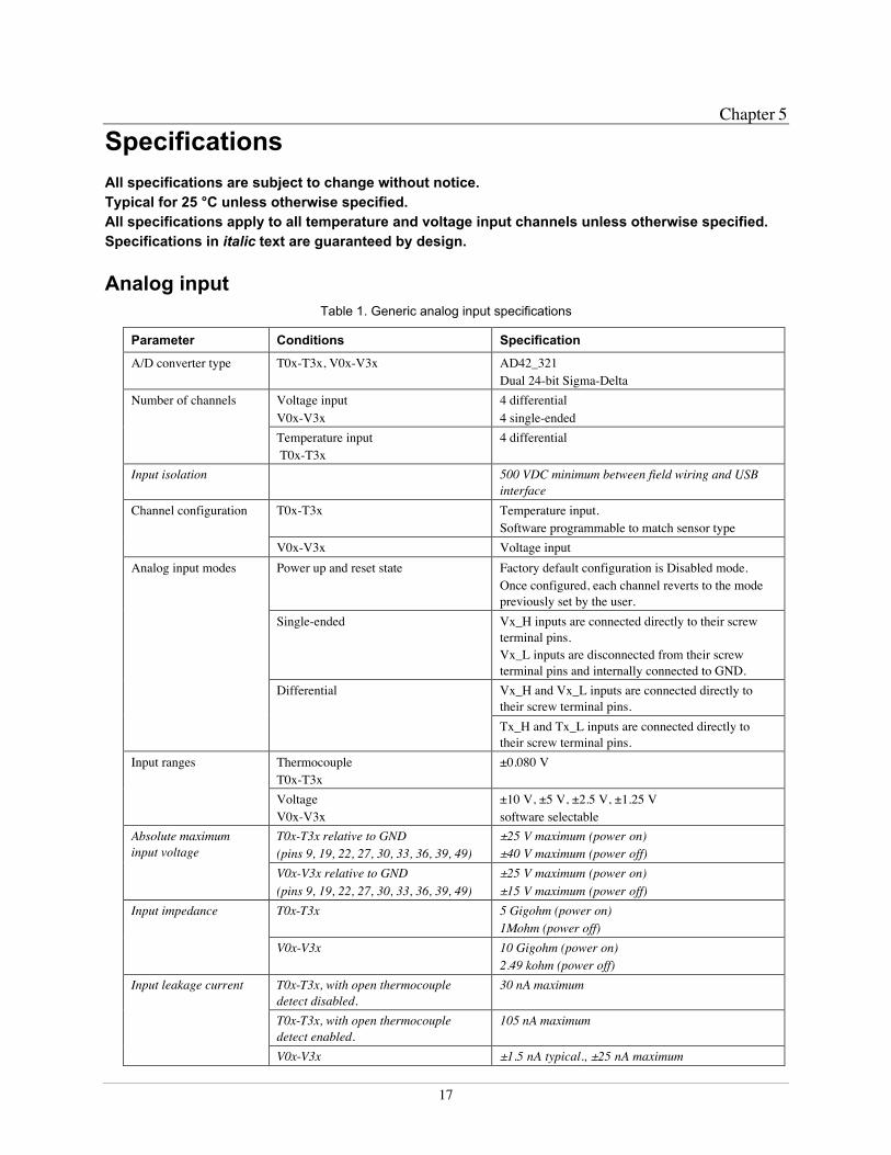
Analog inputTable 1. Generic analog input specifications
Parameter Conditions Specification
A/D converter type T0x-T3x, V0x-V3x AD42_321Dual 24-bit Sigma-Delta
Voltage inputV0x-V3x
4 differential4 single-ended
Number of channels
Temperature input T0x-T3x
4 differential
Input isolation 500 VDC minimum between field wiring and USBinterface
T0x-T3x Temperature input.Software programmable to match sensor type
Channel configuration
V0x-V3x Voltage inputPower up and reset state Factory default configuration is Disabled mode.
Once configured, each channel reverts to the modepreviously set by the user.
Single-ended Vx_H inputs are connected directly to their screwterminal pins.Vx_L inputs are disconnected from their screwterminal pins and internally connected to GND.Vx_H and Vx_L inputs are connected directly totheir screw terminal pins.
Analog input modes
Differential
Tx_H and Tx_L inputs are connected directly totheir screw terminal pins.
ThermocoupleT0x-T3x
±0.080 VInput ranges
VoltageV0x-V3x
±10 V, ±5 V, ±2.5 V, ±1.25 Vsoftware selectable
T0x-T3x relative to GND(pins 9, 19, 22, 27, 30, 33, 36, 39, 49)
±25 V maximum (power on)±40 V maximum (power off)
Absolute maximuminput voltage
V0x-V3x relative to GND(pins 9, 19, 22, 27, 30, 33, 36, 39, 49)
±25 V maximum (power on)±15 V maximum (power off)
T0x-T3x 5 Gigohm (power on)1Mohm (power off)
Input impedance
V0x-V3x 10 Gigohm (power on)2.49 kohm (power off)
T0x-T3x, with open thermocoupledetect disabled.
30 nA maximum
T0x-T3x, with open thermocoupledetect enabled.
105 nA maximum
Input leakage current
V0x-V3x ±1.5 nA typical., ±25 nA maximum

OM-USB-TC-AI User's Guide Specifications
18
Parameter Conditions Specification
T0x-T3x 50 HzInput bandwidth (-3 dB)V0x-V3x 3 kHz
Maximum workingvoltage (signal +common mode)
V0x-V3x ±10.25 V maximum
T0x-T3x, fIN = 60 Hz 100 dBCommon mode rejectionratio V0x-V3x, fIN = 60 Hz, all input ranges 83 dBADC Resolution 24 bitsADC No missing codes 24 bitsInput coupling DCWarm-up time 30 minutes minimumOpen thermocoupledetect
T0x-T3x Automatically enabled when the channel pair isconfigured for thermocouple sensor.The maximum open detection time is 3 seconds.
T0x-T3x, 15 °C to 35 °C ±0.25 °C typical,±0.5 °C maximumCJC sensor accuracyT0x-T3x, 0°C to 70 °C –1.0 to +0.75 °C maximum
Channel configurationsTable 2. Channel configuration specifications
Channel Category Conditions Specification
T0x-T3x Disabled All temperature input channels are disconnected fromscrew terminals and internally connected to GND.
See Note 4
T0x-T3x ThermocoupleNote 1
4 differential channels
V0x-V3x Disabled All voltage input channels are disconnected from screwterminals and internally connected to GND.
See Note 4
V0x-V3x DifferentialNote 2
4 differential channels
V0x-V3x Single-ended 4 single-ended channels
Note 1: Internally, the OM-USB-TC-AI has four, dual-channel, fully differential A/Ds providing a totalof eight input channels.
Note 2: When connecting differential inputs to floating input sources, you must provide a DC return pathfrom each differential input to ground. To do this, connect a resistor from each of the differentialinputs to GND. A value of approximately 1Meg ohm can be used for most applications.
Note 3: Channel configuration information is stored in the EEPROM of the isolated microcontroller bythe firmware whenever any item is modified. Modification is performed by commands issuedover USB from an external application, and the configuration is made non-volatile through theuse of the EEPROM.
Note 4: The factory default configuration is Disabled. The Disabled mode will disconnect thetemperature and voltage inputs from the terminal blocks and internally connect ground (GND) toall of the A/D inputs.

OM-USB-TC-AI User's Guide Specifications
19
Compatible sensors: T0x-T3x
Table 3. Compatible sensor type specifications
Parameter Conditions
J: -210 °C to 1200 °CK: -270 °C to 1372 °CR: -50 °C to 1768 °CS: -50 °C to 1768 °CT: -270 °C to 400 °CN: -270 °C to 1300 °CE: -270 °C to 1000 °C
Thermocouple
B: 0 °C to 1820 °C
Accuracy
Thermocouple measurement accuracy: T0x-T3x
Table 4. Thermocouple accuracy specifications, including CJC measurement error. All specifications are (±)
SensorType
Sensor temperaturerange
Accuracy errormaximum(°C)
Accuracy errortypical(°C)
Tempco
(°C/°C)
-210 °C 2.028 0.7070 °C 0.835 0.278
J
1200 °C 0.783 0.288
0.031
-210 °C 2.137 0.7620 °C 0.842 0.280
K
1372 °C 0.931 0.389
0.035
-50 °C 1.225 0.435250 °C 0.554 0.195
S
1768 °C 0.480 0.157
0.021
-50 °C 1.301 0.458250 °C 0.549 0.190
R
1768 °C 0.400 0.134
0.019
250 °C 2.193 2.185700 °C 0.822 0.819
B
1820 °C 0.469 0.468
0.001
-200 °C 1.976 0.6840 °C 0.954 0.321
E
1000 °C 0.653 0.240
0.030
-200 °C 2.082 0.7440 °C 0.870 0.290
T
400 °C 0.568 0.208
0.035
-200 °C 2.197 0.7600 °C 0.848 0.283
N
1300 °C 0.653 0.245
0.028
OM-USB-TC-AI User's Guide Specifications
20
Note 5: Thermocouple measurement accuracy specifications include polynomial linearization, cold-junction compensation and system noise. These specs are for one year, or 3000 operating hours,whichever comes first, and for operation of the OM-USB-TC-AI between 15 °C and 35 °C. Thereis a CJC sensor on the temperature sensor input side of the module. The accuracy listed aboveassumes the screw terminals are at the same temperature as the CJC sensor. Errors shown do notinclude inherent thermocouple error. Contact your thermocouple supplier for details on the actualthermocouple accuracy error.
Note 6: Thermocouples must be connected to the OM-USB-TC-AI such that they are floating withrespect to GND (pins 9, 19, 22, 27, 30, 33, 36, 39, 49). The OM-USB-TC-AI GND pins areisolated from earth ground. You can connect thermocouple sensors to voltages referenced to earthground as long as the isolation between the GND pins and earth ground is maintained.
Note 7: When thermocouples are attached to conductive surfaces, the voltage differential betweenmultiple thermocouples must remain within ±1.4 V. For best results, we recommend usinginsulated or ungrounded thermocouples when possible.
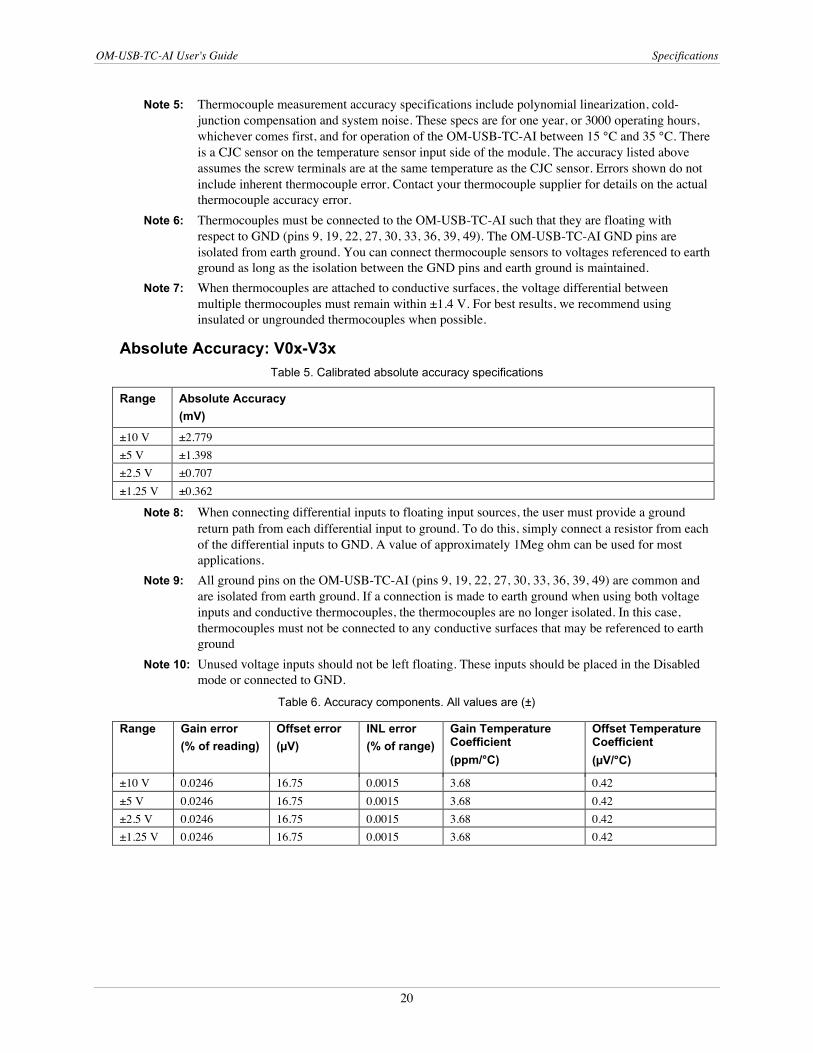
Absolute Accuracy: V0x-V3x
Table 5. Calibrated absolute accuracy specifications
Range Absolute Accuracy
(mV)
±10 V ±2.779±5 V ±1.398±2.5 V ±0.707±1.25 V ±0.362
Note 8: When connecting differential inputs to floating input sources, the user must provide a groundreturn path from each differential input to ground. To do this, simply connect a resistor from eachof the differential inputs to GND. A value of approximately 1Meg ohm can be used for mostapplications.
Note 9: All ground pins on the OM-USB-TC-AI (pins 9, 19, 22, 27, 30, 33, 36, 39, 49) are common andare isolated from earth ground. If a connection is made to earth ground when using both voltageinputs and conductive thermocouples, the thermocouples are no longer isolated. In this case,thermocouples must not be connected to any conductive surfaces that may be referenced to earthground
Note 10: Unused voltage inputs should not be left floating. These inputs should be placed in the Disabledmode or connected to GND.
Table 6. Accuracy components. All values are (±)
Range Gain error
(% of reading)
Offset error
(µV)
INL error
(% of range)
Gain TemperatureCoefficient
(ppm/°C)
Offset TemperatureCoefficient
(µV/°C)
±10 V 0.0246 16.75 0.0015 3.68 0.42±5 V 0.0246 16.75 0.0015 3.68 0.42±2.5 V 0.0246 16.75 0.0015 3.68 0.42±1.25 V 0.0246 16.75 0.0015 3.68 0.42

OM-USB-TC-AI User's Guide Specifications
21
Table 7. Noise performance specifications
Range Peak to peak noise
(µV)
RMS noise
(µVrms)
Noise-Free resolution
(bits)
±10 V 41.13 6.23 19.09±5 V 30.85 4.67 18.51±2.5 V 17.14 2.60 18.36±1.25 V 11.14 1.69 17.98
Table 7 summarizes the noise performance for the OM-USB-TC-AI. Noise distribution is determined bygathering 1000 samples with inputs tied to ground at the user connector. Samples are gathered at the maximumspecified sample rate of 2 S/s.
Settling time: V0x-V3x
Table 8. Settling time specifications
AccuracyRange
±0.0004%
(seconds)
±10 V 15.0±5 V 0.40±2.5 V 0.40±1.25 V 0.40
Settling time is defined as the time required for a channel to settle within a specified accuracy in response to afull-scale (FS) step input.
Analog input calibrationTable 9. Analog input calibration specifications
Parameter Specifications
Recommended warm-up time 30 minutes minimumCalibration Firmware calibrationCalibration interval 1 year
+10.000 V, ±5 mV maximum. Actual measured values stored in EEPROMTempco: 5 ppm/°C maximum
Calibration reference
Long term stability: 30 ppm/1000 h
Throughput rateTable 10. Throughput rate specifications
Number of Input Channels Maximum throughput
1 2 Samples/second2 2 S/s on each channel, 4 S/s total3 2 S/s on each channel, 6 S/s total4 2 S/s on each channel, 8 S/s total5 2 S/s on each channel, 10 S/s total6 2 S/s on each channel, 12 S/s total7 2 S/s on each channel, 14 S/s total8 2 S/s on each channel, 16 S/s total

OM-USB-TC-AI User's Guide Specifications
22
Note 11: The analog inputs are configured to run continuously. Each channel is sampled twice per second.The maximum latency between when a sample is acquired and the voltage/temperature data isprovided by the USB unit is approximately 0.4 seconds.
Digital input/outputTable 11. Digital input/output specifications
Digital type 5V CMOSNumber of I/O 8 (DIO0 through DIO7)Configuration Independently configured for input or output.
Power on reset is input mode.Pull-up/pull-down configuration All pins pulled up to +5 V via 47 K resistors (default). Contact MCC factory for pull-
down to ground (GND) capability.Digital I/O transfer rate(software paced)
Digital input – 50 port reads or single bit reads per second typical. Digital output – 100 port writes or single bit writes per second typical.
Input high voltage 2.0 V minimum, 5.5 V absolute maximum.Input low voltage 0.8 V maximum, –0.5 V absolute minimumOutput low voltage(IOL = 2.5 mA max.)
0.7 V maximum
Output high voltage(IOH = -2.5 mA max.)
3.8 V minimum
Note 12: All ground pins on the OM-USB-TC-AI (pins 9, 19, 22, 27, 30, 33, 36, 39, 49) are common andare isolated from earth ground. If a connection is made to earth ground when using digital I/Oand conductive thermocouples, the thermocouples are no longer isolated. In this case,thermocouples must not be connected to any conductive surfaces that may be referenced toearth ground.
CounterTable 12. CTR I/O specifications
Parameter Conditions Specification
Pin name CTRNumber of channels 1Resolution 32-bitsCounter type Event counterInput type TTL, rising edge triggeredInput source CTR screw terminal
Counter read System dependent, 33 to 1000 reads per second.Counter read/writes rates(software paced) Counter write System dependent, 33 to 1000 reads per second.Schmidt trigger hysteresis 20 mV to 100 mVInput leakage current ±1.0 µA typ.Input frequency 1 MHz max.High pulse width 500 nS min.Low pulse width 500 ns min.Input high voltage 4.0 V min, 5.5 V absolute maxInput low voltage 1.0 V max, –0.5 V absolute min

OM-USB-TC-AI User's Guide Specifications
23
Note 13: All ground pins on the OM-USB-TC-AI (pins 9, 19, 22, 27, 30, 33, 36, 39, 49) are common andare isolated from earth ground. If a connection is made to earth ground with both the counter(CTR) and conductive thermocouples, the thermocouples are no longer isolated. In this case,thermocouples must not be connected to any conductive surfaces that may be referenced toearth ground.
MemoryTable 13. Memory specifications
EEPROM 1,024 bytes isolated micro reserved for sensor configuration256 bytes USB micro for external application use
MicrocontrollerTable 14. Microcontroller specifications
Type Two high-performance 8-bit RISC microcontrollers
USB +5V voltageTable 15. USB +5V voltage specifications
Parameter Specification
USB +5V (VBUS) input voltagerange
4.75 V minimum to 5.25 V maximum
PowerTable 16. Power specifications
Parameter Conditions Specification
Supply current USB enumeration <100 mASupply current(Note 14)
Continuous mode with all inputs configured for Disabledmode.
270 mA typical
User +5V output voltage range(terminal block pin 21)
4.9 V minimum to5.1 V maximum
User +5V output current(terminal block pin 21)
Bus-powered and connected to a self-powered hub.(Note 14)
5 mA maximum
Isolation Measurement system to PC 500 VDC minimum
Note 14: This is the total current requirement for the OM-USB-TC-AI which includes up to 10 mA for thestatus LED.
USB specificationsTable 17. USB specifications
USB device type USB 2.0 (full-speed)Device compatibility USB 1.1, USB 2.0Device power capability Self-poweredUSB cable type A-B cable, UL type AWM 2527 or equivalent. (min 24 AWG VBUS/GND,
min 28 AWG D+/D–)USB cable length 3 meters maximum

OM-USB-TC-AI User's Guide Specifications
24
EnvironmentalTable 18. Environmental specifications
Operating temperature range 0 to 55 ° C maximumStorage temperature range -40 to 85 ° C maximumHumidity 0 to 90% non-condensing maximum
MechanicalTable 19. Mechanical specifications
Dimensions 127 mm (L) x 88.9 mm (W) x 35.56 (H)User connection length 3 meters maximum
Screw terminal connector type and pin outTable 20. Screw terminal connector specifications
Connector type Screw terminalWire gauge range 16 AWG to 30 AWG
Table 21. Screw terminal pin out
Pin Signal Name Pin Description Pin Signal Name Pin Description1 RSVD Reserved, Do Not Use 27 GND2 NC 28 V3L V3 voltage input (-)3 T0H T0 sensor input (+) 29 V3H V3 voltage input (+)4 T0L T0 sensor input (-) 30 GND5 NC 31 V2L V2 voltage input (-)6 RSVD Reserved, Do Not Use 32 V2H V2 voltage input (+)7 T1H T1 sensor input (+) 33 GND8 T1L T1 sensor input (-) 34 V1L V1 voltage input (-)9 GND 35 V1H V1 voltage input (+)10 RSVD Reserved, Do Not Use 36 GND
CJC sensor
11 RSVD Reserved, Do Not Use 37 V0L V0 voltage input (-)12 NC 38 V0H V0 voltage input (+)13 T2H T2 sensor input (+) 39 GND14 T2L T2 sensor input (-) 40 CTR Counter Input15 NC 41 DIO7 Digital Input/Output16 RSVD Reserved, Do Not Use 42 DIO6 Digital Input/Output17 T3H T3 sensor input (+) 43 DIO5 Digital Input/Output18 T3L T3 sensor input (-) 44 DIO4 Digital Input/Output19 GND 45 DIO3 Digital Input/Output20 RSVD Reserved, Do Not Use 46 DIO2 Digital Input/Output21 +5V +5V output 47 DIO1 Digital Input/Output22 GND 48 DIO0 Digital Input/Output23 NC 49 GND24 NC 50 NC25 NC 51 NC26 NC 52 NC

WARRANTY/DISCLAIMEROMEGA ENGINEERING, INC. warrants this unit to be free of defects in materials and workmanship for aperiod of 13 months from date of purchase. OMEGA’s WARRANTY adds an additional one (1) monthgrace period to the normal one (1) year product warranty to cover handling and shipping time. Thisensures that OMEGA’s customers receive maximum coverage on each product. If the unit malfunctions, it must be returned to the factory for evaluation. OMEGA’s Customer ServiceDepartment will issue an Authorized Return (AR) number immediately upon phone or written request.Upon examination by OMEGA, if the unit is found to be defective, it will be repaired or replaced at nocharge. OMEGA’s WARRANTY does not apply to defects resulting from any action of the purchaser,including but not limited to mishandling, improper interfacing, operation outside of design limits, improper repair, or unauthorized modification. This WARRANTY is VOID if the unit shows evidence of having been tampered with or shows evidence of having been damaged as a result of excessive corrosion;or current, heat, moisture or vibration; improper specification; misapplication; misuse or other operatingconditions outside of OMEGA’s control. Components in which wear is not warranted, include but are not limited to contact points, fuses, and triacs.OMEGA is pleased to offer suggestions on the use of its various products. However, OMEGA neither assumes responsibility for any omissions or errors nor assumes liability for anydamages that result from the use of its products in accordance with information provided byOMEGA, either verbal or written. OMEGA warrants only that the parts manufactured by thecompany will be as specified and free of defects. OMEGA MAKES NO OTHER WARRANTIES OR REPRESENTATIONS OF ANY KIND WHATSOEVER, EXPRESSED OR IMPLIED, EXCEPT THAT OFTITLE, AND ALL IMPLIED WARRANTIES INCLUDING ANY WARRANTY OF MERCHANTABILITYAND FITNESS FOR A PARTICULAR PURPOSE ARE HEREBY DISCLAIMED. LIMITATION OF LIABILITY: The remedies of purchaser set forth herein are exclusive, and the total liability of OMEGA with respect to this order, whether based on contract, warranty, negligence, indemnification, strict liability or otherwise, shall not exceed the purchase price of the component upon which liability is based. In no event shall OMEGA be liable for consequential, incidental or special damages.CONDITIONS: Equipment sold by OMEGA is not intended to be used, nor shall it be used: (1) as a “BasicComponent” under 10 CFR 21 (NRC), used in or with any nuclear installation or activity; or (2) in medicalapplications or used on humans. Should any Product(s) be used in or with any nuclear installation oractivity, medical application, used on humans, or misused in any way, OMEGA assumes no responsibilityas set forth in our basic WARRANTY/DISCLAIMER language, and, additionally, purchaser will indemnifyOMEGA and hold OMEGA harmless from any liability or damage whatsoever arising out of the use of theProduct(s) in such a manner.
RETURN REQUESTS/INQUIRIESDirect all warranty and repair requests/inquiries to the OMEGA Customer Service Department. BEFORERETURNING ANY PRODUCT(S) TO OMEGA, PURCHASER MUST OBTAIN AN AUTHORIZED RETURN(AR) NUMBER FROM OMEGA’S CUSTOMER SERVICE DEPARTMENT (IN ORDER TO AVOIDPROCESSING DELAYS). The assigned AR number should then be marked on the outside of the returnpackage and on any correspondence.The purchaser is responsible for shipping charges, freight, insurance and proper packaging to preventbreakage in transit.
FOR WARRANTY RETURNS, please have the following information available BEFORE contacting OMEGA:1. Purchase Order number under which the product
was PURCHASED,2. Model and serial number of the product under
warranty, and3. Repair instructions and/or specific problems
relative to the product.
FOR NON-WARRANTY REPAIRS, consult OMEGAfor current repair charges. Have the followinginformation available BEFORE contacting OMEGA:1. Purchase Order number to cover the COST
of the repair,2. Model and serial number of the product, and3. Repair instructions and/or specific problems
relative to the product.
OMEGA’s policy is to make running changes, not model changes, whenever an improvement is possible. This affordsour customers the latest in technology and engineering.OMEGA is a registered trademark of OMEGA ENGINEERING, INC.© Copyright 2010 OMEGA ENGINEERING, INC. All rights reserved. This document may not be copied, photocopied,reproduced, translated, or reduced to any electronic medium or machine-readable form, in whole or in part, without theprior written consent of OMEGA ENGINEERING, INC.

M4892/0410
Where Do I Find Everything I Need for Process Measurement and Control?
OMEGA…Of Course!Shop online at omega.com SM
TEMPERATURE�� Thermocouple, RTD & Thermistor Probes, Connectors, Panels & Assemblies�� Wire: Thermocouple, RTD & Thermistor�� Calibrators & Ice Point References�� Recorders, Controllers & Process Monitors�� Infrared Pyrometers
PRESSURE, STRAIN AND FORCE�� Transducers & Strain Gages�� Load Cells & Pressure Gages�� Displacement Transducers�� Instrumentation & Accessories
FLOW/LEVEL�� Rotameters, Gas Mass Flowmeters & Flow Computers�� Air Velocity Indicators�� Turbine/Paddlewheel Systems�� Totalizers & Batch Controllers
pH/CONDUCTIVITY�� pH Electrodes, Testers & Accessories�� Benchtop/Laboratory Meters�� Controllers, Calibrators, Simulators & Pumps�� Industrial pH & Conductivity Equipment
DATA ACQUISITION�� Data Acquisition & Engineering Software�� Communications-Based Acquisition Systems�� Plug-in Cards for Apple, IBM & Compatibles�� Data Logging Systems�� Recorders, Printers & Plotters
HEATERS�� Heating Cable�� Cartridge & Strip Heaters�� Immersion & Band Heaters�� Flexible Heaters�� Laboratory Heaters
ENVIRONMENTALMONITORING AND CONTROL�� Metering & Control Instrumentation�� Refractometers�� Pumps & Tubing�� Air, Soil & Water Monitors�� Industrial Water & Wastewater Treatment�� pH, Conductivity & Dissolved Oxygen Instruments