Embed Size (px)
Citation preview
2351-9789 © 2017 The Authors. Published by Elsevier B.V. This is an open access article under the CC BY-NC-ND license (http://creativecommons.org/licenses/by-nc-nd/4.0/).Peer-review under responsibility of the organizing committee of the 45th SME North American Manufacturing Research Conferencedoi: 10.1016/j.promfg.2017.07.078
Procedia Manufacturing 10 ( 2017 ) 898 – 911
Available online at www.sciencedirect.com
ScienceDirect
45th SME North American Manufacturing Research Conference, NAMRC 45, LA, USA
Thermo-mechanical design optimization of conformal cooling channels using design of experiments approach
Suchana A. Jahan, Tong Wu, Yi Zhang, Jing Zhang, Andres Tovar, Hazim Elmounayri*
Department of Mechanical Engineering, Purdue School of Engineering and Technology, IUPUI, Indianapolis, IN-46202, USA
Abstract
Plastic injection molding is a versatile process and a major part of the present plastic manufacturing industry. Traditional die design is limited to straight (drilled) cooling channels, which don’t impart optimal thermal (or thermo-mechanical) performance. With the advent of additive manufacturing technology, design of injection molding tools with conformal cooling channels is now possible. The incorporation of conformal cooling channels can improve the thermal performance of an injection mold, though it may compromise the structural or mechanical stability of the mold. However, optimum conformal channels based on thermo-mechanical performance are not found in the literature. This paper proposes a design methodology to generate optimized designconfigurations of such channels in plastic injection molds. Design of experiments (DOEs) technique is used to study the effect of critical design parameters of conformal channels. In addition, a trade-off technique is utilized to obtain optimum design configurations of conformal cooling channels for “best” thermo-mechanical performance of a mold.
© 2017 The Authors. Published by Elsevier B.V.Peer-review under responsibility of the Scientific Committee of NAMRI/SME.
Keywords: injection molding; conformal cooling channel; design optimization; additive manufacturing
1. Introduction
In the present world, a wide variety of plastic products are used in everyday life. Injection molding is a major part of the plastic industry, consuming a large percentage of the total amount of plastics [1]. Plastic injection molding is a multipurpose process to obtain different complex sizes and shapes of high quality products from thermoplastic and
* Corresponding author. Tel.: +1-317-278-3320; fax: +1-317-274-9744.E-mail address: [email protected]
© 2017 The Authors. Published by Elsevier B.V. This is an open access article under the CC BY-NC-ND license (http://creativecommons.org/licenses/by-nc-nd/4.0/).Peer-review under responsibility of the organizing committee of the 45th SME North American Manufacturing Research Conference

899 Suchana A. Jahan et al. / Procedia Manufacturing 10 ( 2017 ) 898 – 911
thermosetting materials with the application of heat and pressure [2]. To obtain a better-quality plastic part the design of the injection molding tooling, specifically the design of die core and cavity is very critical. It also plays animportant role in the economic aspects of the business. The cooling of injection molding tooling plays very important role in the total production cycle time of the injection molding process. Time is significant in the entire molding process, as it constitutes about half of the time in the overall production cycle [3]. Figure 1 shows a generic distribution of time in the total injection molding process.
Fig. 1. Typical cycle time in injection molding [3].
Fig. 2. Simplified view of traditional mold(left) and 3D printed conformal cooling mold (right).
Injection molding is a widely used and accepted manufacturing process for the production of plastic parts. Traditionally straight holes are drilled into the solid dies to cool the hot molten plastic inside the cavity. This cooling process takes a major portion of the production cycle, leading to high cost of production. At present, with the rising competition worldwide in the plastic product business, it has become very important to lower the production cost, one way of doing so is to reduce the production cycle time. With the currently available manufacturing methods of traditional dies, it is not possible to reach much closer to the cavity wall; precisely, to the rounded corners or sharp edges of an intricate geometry. Hence an innovative technological solution is essential to solve the problem, to cope

900 Suchana A. Jahan et al. / Procedia Manufacturing 10 ( 2017 ) 898 – 911
up with the ongoing business competition. Using conformal cooling channels is a good option for this purpose. Conformal cooling channels are the ones, which “conform” to the shape of the internal cavity wall, thus can reach much closer to the molten plastic material, compared to the cases of traditional molds. With the use of advanced additive manufacturing technology, the shape and size of the channels are no longer limited to larger circular cross-section, rather it is up to the requirement of the optimal channel configuration. Figure 2 shows generic designs of a traditional and conformal channels in similar design of injection molds. The traditional dies are created from a simple block of steel or similar metals using traditional machining methods such as milling and then straight cooling channels are drilled into the mold body. On the other hand, the mold cavity and core with conformal cooling channels can be 3D printed using metal powder and can be given any size and shape as per requirements. With the ongoing research and development in additive manufacturing technology, the printing methods are becoming more and more advanced and efficient day by day. Conformal cooling channels have the potential to improve the performance of the molding dies in terms of uniform and fast cooling, less warping and defects etc., as any design of channels could be produced using additive manufacturing process to create an optimal solution to this problem.Hence, the research concentrates on achieving a proper design methodology for conformal cooling channels and conducting thermos-mechanical analyses for optimization.
2. Literature review
The use of cooling channels conformal to the molding cavity improves the control of mold temperature and part dimensions. This has been reported by a group at MIT in the 1990’s [4]. A systematic, modular approach was presented by Xu and Sachs at MIT for the design of conformal cooling channels. They recognized cooling as local to the surface of the tool and divided the tool in different geometric regions and created the channel systems for each region. Mold surface temperature, pressure drop, mold material strength etc. were considered as design parameters in their study [4-6]. Three-dimensional printing was applied to the direct fabrication of tooling using metal powders. In their process of applying additive manufacturing technology, they provided improvement of the areas of thermal management, dimensional control, surface finishing and tool hardening. They used stainless steel powder with a resultant tooling hardness of 25-30 Rockwell C [7].
Ferreira and Mateus presented a study on rapid soft tooling for plastic injection molding. The main purpose of their study was to propose some original approaches to integrate the advanced processing technologies, with composite materials chilled by conformal cooling channels to manufacture injection molding tools [8]. The effect of conformal cooling channel to reduce cooling time and increase part quality, compared to traditional straight cooling channels was also presented by Meckley and Edwards. The used high density polyethylene and polycarbonate in their study and demonstrated the mold and melt temperature differences between the two materials to illustrate the conformal channels efficiency[9]. Hopkins and Dickens demonstrated the use of conformal cooling channels to both heat and cool a single injection molding tool. This provided potential of 3D printing technology to achieve successful production of complex geometries [10]. One of the advantages of rapid tooling methods in building conformal heating or cooling channels to enhance thermal control. An important issue of such tooling is to seal the channels rapidly and inexpensively. Yoo provided an investigation on this matter in 2008[11].
Altaf et al. presented a technique of fabricating conformal cooling channels in an aluminum filled epoxy mold using rapid prototyping techniques. This paper provided an insight on conformal channel fabrication method, which is not possible using traditional drilling or machining process[12]. An investigation of the automation of preliminary design stage to the layout design stage of the cooling system design process is presented by Li et al. This study provides a configuration of straight cooling channels based on the size and shape of the plastic part design, and does not necessarily require additive manufacturing technique[13].
Though there have been a series of studies in the area of design and modeling of conformal cooling channels in injection molding tooling, the concept of simulating the designs cannot be rooted back to more than 10 years. Since then, different simulation packages have been used to analyze the tool and channel designs. Moldflow analysis in I-DEAS™ was used by Dimla et al. in 2005 to find the best position of the runner [3]. ABM Saifullah and SH Masood analyzed part cooling times using ANSYS thermal analysis software 2007 [14]. In 2009, this same group used MPI simulation software for part analysis and compared results for conventional and square section conformal cooling channels; concluding conformal channels render 35% less cooling time than conventional ones [15]. They incorporated a square sectioned conformal cooling channel system for injection mold dies and provided comparative

901 Suchana A. Jahan et al. / Procedia Manufacturing 10 ( 2017 ) 898 – 911
studies between conformal and traditional molds[16]. They also provided finite element analysis using ANSYS was presented for a mold with bimetallic conformal cooling channels. The performance was compared with a conventional mold and experimental verification was also provided with two different plastic materials being produced by miniature injection molding machine [15]. A quantitative guidance for tooling design was presented in 2009 by Xu and Sachs. Their proposed methodology was tested on a 3D printed benchmark tool with truss support. In their study, preliminary tests demonstrated the technical feasibility of using SFF process to fabricate low thermal inertia tools [17].
Sun et al provided a finite element study of milled groove insert method for cooling of plastic injection molds using a household iron plastic part [18]. The numerical analysis technique was based on cooling and thermal stress modeling [19]. Gloinn et al. from Ireland performed FEA analysis to determine mold temperature using ABS
[20]. Another study was conducted using Moldflow Plastic Insight 3.1 to investigate the thermal effects of cooling channel design on injection molding in 2007 by Au and Yu [21]. They proposed a novel scaffold for the design of uniform conformal cooling. In their study in 2013, Hsu et al. identified that for cavities with irregular geometry, the distance between cooling channels and cavity varies throughout the part and causes local heat accumulation and product defects such as sink mark, warpage etc. They adopted a true three-dimensional simulation technique to predict cooling time and compare the results with traditional molds [22]. Dang and Park adopted an algorithm for calculating the temperature distribution through molding thicken and presented a conformal channel with array of baffles to obtain uniform cooling over the entire free-form surface of molded parts [23]. They also provided an insight into the use of conformal cooling channels to provide a uniform cooling and reducing the cycle time for injection molding process. They presented U-shaped milled groove conformal channels and proposed an optimization process to obtain an optimal conformal channels configuration [24]. The comparative effect of conventional, series, parallel and additive parallel cooling channels was studied by Khan et al. in 2014 with respect to cooling time, total cycle time, volumetric shrinkage and temperature variance using AMI software [25].
Wang et al. in 2011 presented an automatic method for designing conformal cooling circuits by establishing a relationship between the conformal cooling and the shape of the plastic body[26]. Choi et al. recognizes the higher degree of freedom in the design of conformal cooling channels with the application of 3D printing and concentrate on a branching law principle to improve the cooling efficiency in injection molds. They used Voronoi diagram algorithm and binary branching algorithm to create the design of conformal cooling channels[27]. A similar technique was also adopted by Park and Pham. They designed cooling channels for individual surfaces and then combined them to form overall conformal cooling channel system for the entire part[28]. Two years later, theydesigned conformal cooling channels for an automotive part using the algorithm they provided in their previous studies. In this paper, they conducted an optimization to minimize the cooling time with boundaries ensuring a realistic design for cooling system [29]. Wang et al. introduced an approach to generate spiral channels for conformal cooling using an algorithm. With the help of boundary distance maps, their algorithm was investigated to generate evenly distributed spiral channels in the injection mold[30].
In 2011, Au and Yu presented a methodology called visibility based cooling channel generation for automatic preliminary cooling channel design. This is a more geometric and theoretical method, rather than adopted in practical scenario[31]. After that, they provided the cooling channel distance modification based on adjustment direction and adjustment amount in 2014. Also, a simulation technique using Moldflow Plastic Insight was adopted to demonstrate the feasibility of their proposed method[32]. A new methodology called “Morpho Cooling” was proposed by Agazzi et al. for the design of cooing channels in injection mold. This technique provided better results in cooling in terms of higher uniformity of temperature and lesser part warpage[33].
Though there has been a lot of studies about the analysis of conformal cooling channels, the number of studies dedicated to the design parameters of conformal channels for various kinds of part design is very limited. Till date, most of the designs has been done based on the designers’ experiences. Also, any kind of mix and match between the design parameters, cross section size and respective experimental analyses is quite rare according to the author’s knowledge. Yet, some preliminary information could be gathered from the literature that act as a basis for further research in this project. For example, a simple relationship between 4 parameters for the design of conformal cooling channels using additive manufacturing is found from Mayer [34].

902 Suchana A. Jahan et al. / Procedia Manufacturing 10 ( 2017 ) 898 – 911
Table 1. A rule of thumb for conformal cooling channel designs in 3D printed molds[34].
3. Methodology
In this paper, a combined thermo-mechanical optimization technique is adopted to obtain the best performing injection mold with conformal cooling channels. A simple cylindrical plastic part has been chosen for the case study. The part design is already mentioned in the previous publication of the authors[35].
The Design of experiments is based on the fact that, for additively manufactured printed injection molds, the channel design depends on the design, size and shape of the plastic part to be molded. Important design parameters are channel diameter (for circular channel), pitch distance etc. The relationships among different design parameters of conformal cooling channels are shown in Table 1. The independent parameter is the wall thickness of the molded part (Column 1 in Table 1), which depends totally on the customer’s requirement and the mold designer does not have any choice in selecting this. The parameter in Column 2, i.e.; channel diameter is based on the Column 1, and the mold designer can choose any number as D in the given range. After choosing the value of D, the designer can choose the value of P and L in the given range, based on the value of D. For example, if D is 6 mm, then P can be any value in the range of 12mm-18mm and L can be any value in between 8mm and 12mm. The parameters are illustrated in the schematic diagram in Figure 3[35, 36]. Some studies show that the use of different cross section for channels other than circular might provide better cooling efficiency. This is to be noticed that the Table 1 is based on circular channels only. If the mold designer wants to create other channel cross sections such as rectangular or square or triangular shape, he can keep the section perimeter same and design the other variables accordingly.
Fig. 3. Schematic diagram of a die cavity with parameter definition.
To create a simple cylindrical plastic cap by injection molding process, the mold cavity and core design is dependent on the plastic cap design itself. The designer can create required configuration of cooling channels. In this study, several conformal channel design configurations have been developed using Design of Experiments approach and each of the designs has been incorporated into same mold cavity and core and the thermo-mechanical
Wall thickness of molded part (mm)
Channel diameter, D (mm) Pitch distance, P (mm) Channel centerline to mold wall distance, L (mm)
0 - 2 4 – 8 2D – 3D 1.5D – 2D
2 - 4 8 – 12 2D – 3D 1.5D – 2D
4 - 8 12 – 14 2D – 3D 1.5D – 2D

903 Suchana A. Jahan et al. / Procedia Manufacturing 10 ( 2017 ) 898 – 911
performance of the full mold has been analyzed. The results are also compared to the same design of mold cavity and core with traditional straight cooling channels.
3.1. The thermal analysis model
During the injection molding process, hot molten plastic is injected into the mold cavity via the injection unit and cooling water is passed through the cooling channels. The water serves two purposes. First, to cool down the hot plastic and second, to warm up the cavity and core body. This warming up process is required to ensure minimum shrinkage of the plastic part being produced. Hence this is understandable that the cooling water’s temperature is needed to be above the temperature of the mold cavity and core. The water temperature is kept couple of degrees higher than the room temperature. As the study is concerned on the cooling process and the phenomena happening after the molten hot plastic is inside the cavity; at time, t=0, cooling water starts running inside the channel. The molten plastic is considered to be already inside the cavity.
To analyze the thermal behavior of the mold with hot molten plastic inside the cavity and cooling water running through the channels, a transient thermal analysis model is developed using ANSYS™ workbench 14.5. An initial temperature of the molten plastic of 168°C, and a water temperature at the inlet of 28°C were used. Convection heat transfer co-efficient is applied on the cooling channel surfaces. This convection heat transfer co-efficient is based on the flow rate of water inside the cooling channels. Fine meshing with medium smoothing is applied on the geometry using automatic mesh generator in ANSYS™, which generated 94,088 elements and 155,990 nodes. The minimum edge length used is 0.75mm. The material properties and boundary conditions are shown in Table 2 and Table 3 respectively [37]. The thermal analysis model have been validated with experimental studies found in literature and the validation study has been described in the previous publications of the authors[38].
Table 2. Material properties for thermal analysis.
Table 3. Initial and boundary conditions for thermal model.
3.2. The structural analysis model
By introducing conformal channels, the designer is creating more void space in the die cavity and core compared to a traditional mold. As such, the mold with conformal channels needs to be analyzed for structural stability. A static structural analysis model is developed in ANSYS Workbench 14.5. The boundary conditions collected from industry consist of: A clamping force of 110 ton, which is applied to the top and bottom surfaces of the mold; an injection pressure of 1.91MPA which is applied on the heating surface. The structural analysis predicts the deformation and distribution of von-mises stress on the mold body. If the maximum von-mises stress is below the acceptable limit of yield strength of mold material, then the mold can be considered as structurally stable.
Material Polypropylene Structural Steel
Density (kg/m3) 830 7850
Thermal conductivity (W/m-K) 0.14 60.5
Specific heat (J/kg-K) 434 1900
Boundary and initial condition Temperatures (°C)
Coolant water inlet 28
Molten plastic temperature 168
Ejection temperature 50

904 Suchana A. Jahan et al. / Procedia Manufacturing 10 ( 2017 ) 898 – 911
3.3. Optimization technique
The optimization of design variables of conformal cooling channel is done by a trade-off study. A set of design of experiments is created to analyze both the thermal and structural behavior of the molds with different configuration of conformal channels. The optimization problem statement is as follows:
Objective function: Minimize, cooling time Minimize, maximum von-mises stress
Design variables: Channel diameter, D Channel pitch distance, P Mold wall to channel centerline distance, L
Constraints: Cooling time < 28.04s (the conventional cooling time) Maximum von-mises stress < 280 MPa 4mm < D < 8mm 8mm < P < 24mm L= 6mm
The objective of the optimization problem is to obtain such a design of conformal cooling channel, such that both the cooling time and the maximum von-mises stress are minimized. For the design of cooling channels, initial consideration is the design of the plastic part to be molded. The chosen design of the plastic part is a simple cylindrical bowl with 1.5mm wall thickness, 50mm height and 80 mm outer diameter. The core and cavity are 55 mm of height and, length and width were around 120mm.As per the recommendation in Table 1, the diameter of the cooling channel should be in the range of 4mm to 8mm. The range of pitch distance, P is 2D to3D; which means for the minimum diameter of 4mm, P is 8mm to12mm and for the maximum value of D=8mm, the range of P is 16mm to 24mm. Hence for the full range of D, the range of P becomes 8mm to 24mm. Similarly, the range of channel centerline to mold wall distance, L can be derived. But, a previous study of this research group provides a result that the minimum value of L can provide the maximum cooling, hence the minimum cooling time [35]. For this reason, the value of L is kept fixed as the minimum of 6mm (minimum diameter 4mm; minimum value of L = 1.5D =6mm) for all the design cases in this study.
In a traditional mold with straight cooling channels, only variables for the design of cooling channels are D and L. As the channels are drilled into the solid mold body, they can only be of circular shaped with the sizes limited by the sizes of drill bits. Generally four straight channels are drilled along four sides of the mold. The channels are then connected in a series combination using taps. Multiple channels in parallel combination(for example in a spiral manner) cannot be drilled inside,. Hence the cooling channels diameters are larger than the conformal cooling channels to keep sufficient amount of water flowing inside. Typically, for a plastic part of 1.5mm thickness, the cooling channel diameter ranges from 8mm to11mm. On the other hand, smaller diameter conformal channels can be built inside the 3D printed molds, as longer path of cooling channels can be built inside and thus increasing the total channel surface area. This finally results in better coling. A comparative understanding can be developed about the geometry of traditional and conformal mold from Figure 2.
The important constraints for the optimization problem are cooling time and maximum von-mises stress. The basic idea is that we need to decrease the cooling time that we can generally achieve by traditional molds. The traditional mold (straight cooling channels, diameter=10mm) for the production of a cylindrical plastic cap (dimensions described in section 3.3, paragraph 2) provides cooling time of 28.04s. The results are shown in Figure 6 (left) for the traditional mold. This result provides a refernce point for the optimization problem. The design constraint cooling time is set as less that 28.04s accordingly. The yield strength of sructural steel being ~ 420MPa, the limit of maxmimum von-mises stress is set to be less than 280 MPa, considering safely factor 1.5.
905 Suchana A. Jahan et al. / Procedia Manufacturing 10 ( 2017 ) 898 – 911
4. Results and discussion
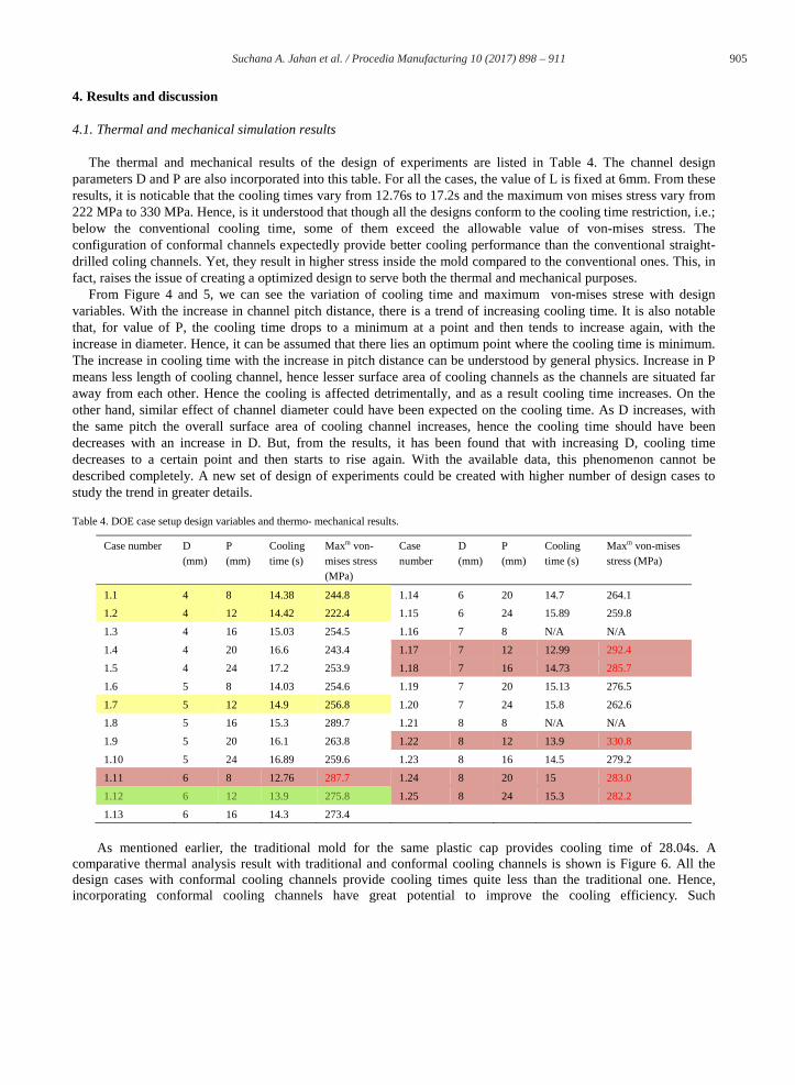
4.1. Thermal and mechanical simulation results
The thermal and mechanical results of the design of experiments are listed in Table 4. The channel design parameters D and P are also incorporated into this table. For all the cases, the value of L is fixed at 6mm. From these results, it is noticable that the cooling times vary from 12.76s to 17.2s and the maximum von mises stress vary from 222 MPa to 330 MPa. Hence, is it understood that though all the designs conform to the cooling time restriction, i.e.; below the conventional cooling time, some of them exceed the allowable value of von-mises stress. The configuration of conformal channels expectedly provide better cooling performance than the conventional straight-drilled coling channels. Yet, they result in higher stress inside the mold compared to the conventional ones. This, in fact, raises the issue of creating a optimized design to serve both the thermal and mechanical purposes.
From Figure 4 and 5, we can see the variation of cooling time and maximum von-mises strese with design variables. With the increase in channel pitch distance, there is a trend of increasing cooling time. It is also notable that, for value of P, the cooling time drops to a minimum at a point and then tends to increase again, with the increase in diameter. Hence, it can be assumed that there lies an optimum point where the cooling time is minimum. The increase in cooling time with the increase in pitch distance can be understood by general physics. Increase in P means less length of cooling channel, hence lesser surface area of cooling channels as the channels are situated far away from each other. Hence the cooling is affected detrimentally, and as a result cooling time increases. On the other hand, similar effect of channel diameter could have been expected on the cooling time. As D increases, with the same pitch the overall surface area of cooling channel increases, hence the cooling time should have been decreases with an increase in D. But, from the results, it has been found that with increasing D, cooling time decreases to a certain point and then starts to rise again. With the available data, this phenomenon cannot be described completely. A new set of design of experiments could be created with higher number of design cases to study the trend in greater details.
Table 4. DOE case setup design variables and thermo- mechanical results.
As mentioned earlier, the traditional mold for the same plastic cap provides cooling time of 28.04s. A comparative thermal analysis result with traditional and conformal cooling channels is shown is Figure 6. All the design cases with conformal cooling channels provide cooling times quite less than the traditional one. Hence, incorporating conformal cooling channels have great potential to improve the cooling efficiency. Such
Case number D(mm)
P(mm)
Cooling time (s)
Maxm von-mises stress (MPa)
Case number
D(mm)
P(mm)
Cooling time (s)
Maxm von-mises stress (MPa)
1.1 4 8 14.38 244.8 1.14 6 20 14.7 264.1
1.2 4 12 14.42 222.4 1.15 6 24 15.89 259.8
1.3 4 16 15.03 254.5 1.16 7 8 N/A N/A
1.4 4 20 16.6 243.4 1.17 7 12 12.99 292.4
1.5 4 24 17.2 253.9 1.18 7 16 14.73 285.7
1.6 5 8 14.03 254.6 1.19 7 20 15.13 276.5
1.7 5 12 14.9 256.8 1.20 7 24 15.8 262.6
1.8 5 16 15.3 289.7 1.21 8 8 N/A N/A
1.9 5 20 16.1 263.8 1.22 8 12 13.9 330.8
1.10 5 24 16.89 259.6 1.23 8 16 14.5 279.2
1.11 6 8 12.76 287.7 1.24 8 20 15 283.0
1.12 6 12 13.9 275.8 1.25 8 24 15.3 282.2
1.13 6 16 14.3 273.4

906 Suchana A. Jahan et al. / Procedia Manufacturing 10 ( 2017 ) 898 – 911
configurations can not only decrease the cooling time, but can also increase uniformity in temeperature distribution, thus resulting in better part quality and lesser defects.
The stress variation does not seem to be as simple as the variation of cooling time with the design variables. There is an increasing trend of von-mises stress with the increase in diameter. It can be explained by the fact that, with increase in diameter, there is more void space in the mold, hence the stresses become higher. For the increase in design variable P, the maximum von-mises stress increases first, and then starts to drop down to minimum values. It is important to note here that, the design cases consist of detached set of parameters and hence the effect of design variables can be better explained with higher number of design cases. In some of the design cases ( Case number: 1.11, 1.17, 1.18, 1.22, 1.24, 1.25) values of maximum von-mises stress exceed the allowable value of 280 MPa. In other cases, they are in the acceptable range. In the study with traditional mold, the value of maximum von-mises stress was found to be 153MPa, the result of which is shown in Figure 7.
Fig. 4. Variation of cooling time with design variables D and P.
Fig. 5. Variation of maximum von-mises stress with design variables D and P.
6
8
10
12
14
16
18
3 4 5 6 7 8 9
Coo
ling
Tim
e (s
)
Channel diameter, D (mm)
Cooling time variation
P=8mm
P=12mm
P=16mm
P=20mm
P=24mm
200
230
260
290
320
350
3 4 5 6 7 8 9
Max
imum
von
-mse
s st
ress
(M
Pa)
Channel diameter, D (mm)
Maximum von-mises stress variation
P=8mm
P=12mm
P=16mm
P=20mm
P=24mm

907 Suchana A. Jahan et al. / Procedia Manufacturing 10 ( 2017 ) 898 – 911
Fig. 6. Comparative thermal analysis result on the plastic part, left- with straight channels, right- with conformal channels (case number1.12).
Fig. 7. Comparative mechanical analysis result on mold, left- with straight channels, right- with conformal channels (case number1.12).
4.2. Optimization results
The case number 1.11, 1.17 and 1.22 have the lowest cooling times of 12.76s, 12.99s and 13.9s respectively. But, in these cases, the values of maximum von-mises stress exceed the allowable stress limit 280MPa. Consequently, these cases cannot be selected as optimum ones. On a different perspective, the minimum vaues of maximum von-mises stress are 222.4 MPa. 243.4MPa and 253.9MPa in case 1.2, 1.4 and 1.5 respectively. In these cases, the cooling times are 14.42s, 16.6s and 17.2s. These values are below the traditional cooling time 28.04, hence can provide good cooling performances as expected.
In this situation, rises the issue of optimization. Is it okay to rely mostly on the cooling time, or is the maximum von mises stress is more important to look into? In injection molding business, the most important problem in the long production cycle that consititues largely of the cooling time. Hence, if any design configuration can provide better cooling and can withstand the structural loads, the designers are satisfied with that. With this consideration in mind, we can chose the design case 1.12 as the optimal design solution to ur optimization problem. It provides a cooling time 13.9s and maximum von-mises stress of 275.8MPa. The channel configuration is D=6mm, P=12mm, L=6mm.
We can notice from the results in Table 4 that case 1.1, 1.2 and 1.7 have cooling times around 14s and maximum von mises stresses around 250MPa. If any designer is conscious about the structural stability of the mold and wants to consider 1s more time in cooling, these three cases would be of great choice for him. The design of conformal cooling channels, and the overall mold is not exact science, rather an art form. The choice of design variables in practical scenerio is not entirely dependent upon the mechanical and thermal behavior. There are some geometric contstraints such as, position of runner, ejector pins, etc. too. Hence, the most suited optimum design configuration can be chosen by the mold designer as per the specific design problem of conformal cooling channels.

908 Suchana A. Jahan et al. / Procedia Manufacturing 10 ( 2017 ) 898 – 911
4.3. Material properties
The thermal and mechanical analysis presented above is based on the traditional material properties of the mold. But, while the molds are to be printed by additive manufacturing, the properties of printed material are a bit different than that of the traditional ones. Some of the material properties of printed specimen are obtained by experimental methods. These properties can be utilized to run all the thermal and mechanical analysis of the DOE cases to obtain a better approximation of the mold behavior. The material properties of 15-5 PH1stainless steel powder obtained by experimental methods are listed in Table 5. The mechanical and thermal properties for 15-5PH1 are from the published EOS data sheet[39].
Table 5. Experimentally derived material properties of printed steel.
Comparing the properties of Table 2 and Table 5, it is understood that there is a variation in the properties of solid steel and 3D printed steel. The density of solid steel is 7850 kg/m3, whereas the 3D printed one has density 7800 kg/m3. Though these values are quite close, there is a large variation in the thermal properties of the solid and printed steel. The thermal conductivity reduces to 13.8 W/m-K in printed steel from 60.5 W/m-K in the solid steel. As in the 3D printed steel, the molecules are loosely packed compared to solid steel, there is larger amount of air gap, hence the thermal conductivity reduces largely.
Fig. 8. Comparative thermal analysis result with traditional and printed steel properties.
In this circumstances, it is essential to study the effect of 3D printed material properties for the mold thermal and structural performances. All the results listed in Table 4 is based on the traditional solid steel properties. To check the variation between the traditional and printed properties, case 1.12 has been selected. The same configuration of
Material property of printed steel specimen Experimentally obtained value
Yield strength 1050 MPa
Ultimate tensile strength 1150 MPa
Young’s modulus 100 GPa
Density 7800 kg/m3
Thermal conductivity 13.8 W/m-K

909 Suchana A. Jahan et al. / Procedia Manufacturing 10 ( 2017 ) 898 – 911
conformal cooling channels has been simulated both with traditional and printed properties. The results are shown in Figure 8 and 9. The cooling time increases to 19.8s, which was 13.9s in the traditional steel case. On the other hand, the maximum von-mises stress does not vary that much and it is steel within the allowable stress limit. This phenomenon can be explained by the fact that the thermal conductivity is highly reduced to 13.8 W/m-K in printed steel, which was 60.5 in the traditional steel mold. Yet, it is important to analyse all the design cases with experimentally driven material properties to obtain a proper optimization of the design configurations.
Fig. 9. Comparative mechanical analysis result with traditional and printed steel properties.
5. Conclusion and future work
In this research, a design methodology to introduce conformal cooling channels in traditional dies is developed and demonstrated using design of experiments approach. Considering thermal and mechanical performance of the molds with conformal cooling channels, optimum design solutions have been obtained. A conformal cooling channel configuration with D=6mm, P=12mm and L=6mm has been chosen as the optimal design. The mold designer can follow the approach and design the conformal cooling channel configuration depending on the problem-specific geometric and design constraints in industry. The traditional mold and 3D printed mold has different thermal and structural properties and those are also considerable factors while designing the injection molds. The results obtained throughout the paper is based on numerical analysis, though the models are validated based on previous experimental studies in the similar field. Moreover, the optimization needs to be done using experimentally derived 3D printed material properties for further accurate results. The optimum design can be incorporated into existing injection molding dies with use of additive manufacturing DMLS technology. The authors are currently working on working creating a conformal cooling channel mold using additive manufacturing technology. The printed mold will be tested in actual injection molding press to verify the performance in near future. The results are expected to provide new effective guidelines for mold designers to select optimum conformal cooling channels.
Acknowledgements
The authors would like to acknowledge Walmart and the Walmart Foundation for supporting this research effort. Hewitt Molding Company provided the original injection mold model for this investigation. 3D Parts Manufacturing
910 Suchana A. Jahan et al. / Procedia Manufacturing 10 ( 2017 ) 898 – 911
3D printed all metallic parts. Any opinions, findings, conclusions, and recommendations expressed in this investigation are those of the writers and do not necessarily reflect the views of the sponsors.
References
[1] Rosato, D.V. and M.G. Rosato, Injection molding handbook. 2012: Springer Science & Business Media.[2] Zheng, R., R.I. Tanner, and X.-J. Fan, Injection molding: integration of theory and modeling methods. 2011: Springer Science & Business
Media.[3] Dimla, D., M. Camilotto, and F. Miani, Design and optimisation of conformal cooling channels in injection moulding tools. Journal of
Materials Processing Technology, 2005. 164: p. 1294-1300.[4] Xu, X., et al. Designing conformal cooling channels for tooling. in Solid Freeform Fabrication Proceedings. 1998.[5] Xu, X., E. Sachs, and S. Allen, The design of conformal cooling channels in injection molding tooling. Polymer Engineering & Science,
2001. 41(7): p. 1265-1279.[6] Sachs, E., et al., Production of injection molding tooling with conformal cooling channels using the three dimensional printing process.
Polymer Engineering and Science, 2000. 40(5): p. 1232-1247.[7] Sachs, E., et al. Progress on tooling by 3D printing; conformal cooling, dimensional control, surface finish and hardness. in Proceedings of
the Eighth Annual Solid Freeform Fabrication Symposium. 1997.[8] Ferreira, J. and A. Mateus, Studies of rapid soft tooling with conformal cooling channels for plastic injection moulding. Journal of Materials
Processing Technology, 2003. 142(2): p. 508-516.[9] Meckley, J. and R. Edwards, A Study on the design and effectiveness of conformal cooling channels in rapid tooling inserts. The
Technology Interface Journal, 2009. 10(1): p. 1-28.[10] Hopkinson, N. and P. Dickens. Conformal cooling and heating channels using laser sintered tools. in Solid freeform fabrication conference,
Texas. 2000.[11] Yoo, S. Design of conformal cooling/heating channels for layered tooling. in Smart Manufacturing Application, 2008. ICSMA 2008.
International Conference on. 2008. IEEE.[12] Altaf, K., A.M.A. Rani, and V.R. Raghavan. Fabrication of circular and Profiled Conformal Cooling Channels in aluminum filled epoxy
injection mould tools. in National Postgraduate Conference (NPC), 2011. 2011. IEEE.[13] Li, C., C. Li, and A. Mok, Automatic layout design of plastic injection mould cooling system. Computer-Aided Design, 2005. 37(7): p. 645-
662.[14] Saifullah, A. and S. Masood, Finite element thermal analysis of conformal cooling channels in injection moulding. 2007.[15] Saifullah, A., S. Masood, and I. Sbarski. New cooling channel design for injection moulding. in Proceedings of the World Congress on
Engineering. 2009.[16] Saifullah, A. and S.H. Masood. Optimum cooling channels design and Thermal analysis of an Injection moulded plastic part mould. in
Materials Science Forum. 2007. Trans Tech Publ.[17] Xu, R.X. and E. Sachs, Rapid thermal cycling with low thermal inertia tools. Polymer Engineering & Science, 2009. 49(2): p. 305-316.[18] Sun, Y., K. Lee, and A. Nee, The application of U-shape milled grooves for cooling of injection moulds. Proceedings of the Institution of
Mechanical Engineers, Part B: Journal of Engineering Manufacture, 2002. 216(12): p. 1561-1573.[19] Sun, Y., K. Lee, and A. Nee, Design and FEM analysis of the milled groove insert method for cooling of plastic injection moulds. The
International Journal of Advanced Manufacturing Technology, 2004. 24(9-10): p. 715-726.[20] ó Gloinn, T., et al., FEA simulation of conformal cooling within injection moulds. International Journal of Manufacturing Research, 2007.
2(2): p. 162-170.[21] Au, K. and K. Yu, A scaffolding architecture for conformal cooling design in rapid plastic injection moulding. The International Journal of
Advanced Manufacturing Technology, 2007. 34(5-6): p. 496-515.[22] Hsu, F., et al., Investigation on conformal cooling system design in injection molding. Advances in Production Engineering & Management,
2013. 8(2): p. 107.[23] Park, H.-S. and X.-P. Dang, Optimization of conformal cooling channels with array of baffles for plastic injection mold. International
Journal of Precision Engineering and Manufacturing, 2010. 11(6): p. 879-890.[24] Dang, X.-P. and H.-S. Park, Design of U-shape milled groove conformal cooling channels for plastic injection mold. International Journal of
Precision Engineering and Manufacturing, 2011. 12(1): p. 73-84.[25] Khan, M., et al., Cycle Time Reduction in Injection Molding Process by Selection of Robust Cooling Channel Design. ISRN Mechanical
Engineering, 2014. 2014.[26] Wang, Y., et al., Automatic design of conformal cooling circuits for rapid tooling. Computer-Aided Design, 2011. 43(8): p. 1001-1010.[27] Choi, J.H., et al. Study on an Optimized Configuration of Conformal Cooling Channel by Branching Law. in ASME 2014 12th Biennial
Conference on Engineering Systems Design and Analysis. 2014. American Society of Mechanical Engineers.[28] Park, H.S. and N.H. Pham, Automatically generating conformal cooling channel design for plastic injection molding. Annals of DAAAM &
Proceedings, 2007: p. 539-541.[29] Park, H.-S. and N.H. Pham, Design of conformal cooling channels for an automotive part. International Journal of Automotive Technology,
2009. 10(1): p. 87-93.[30] Wang, Y., K.-M. Yu, and C.C. Wang, Spiral and conformal cooling in plastic injection molding. Computer-Aided Design, 2015. 63: p. 1-11.[31] Au, K., K. Yu, and W. Chiu, Visibility-based conformal cooling channel generation for rapid tooling. Computer-Aided Design, 2011. 43(4):
p. 356-373.[32] Au, K. and K. Yu, Variable Distance Adjustment for Conformal Cooling Channel Design in Rapid Tool. Journal of Manufacturing Science
and Engineering, 2014. 136(4): p. 044501.

911 Suchana A. Jahan et al. / Procedia Manufacturing 10 ( 2017 ) 898 – 911
[33] Agazzi, A., et al. Uniform cooling and part warpage reduction in injection molding thanks to the design of an effective cooling system. in Key Engineering Materials. 2013. Trans Tech Publ.
[34] Mayer, S., Optimised mould temperature control procedure using DMLS. EOS Whitepaper, EOS GmbH Ltd, 2005: p. 1-10.[35] Jahan, S.A. and H. El-Mounayri, Optimal Conformal Cooling Channels in 3D Printed Dies for Plastic Injection Molding. Procedia
Manufacturing, 2016. 5: p. 888-900.[36] Jahan, S.A., et al., Implementation of Conformal Cooling & Topology Optimization in 3D Printed Stainless Steel Porous Structure Injection
Molds. Procedia Manufacturing, 2016. 5: p. 901-915.[37] Wu, T., et al., A Framework for Optimizing the Design of Injection Molds with Conformal Cooling for Additive Manufacturing. Procedia
Manufacturing, 2015. 1: p. 404-415.[38] Jahan, S.A., Optimization of conformal cooling channels in 3D printed plastic injection molds. 2016.
[39] GmbH, E., http://gpiprototype.com/images/PDF/EOS-StainlessSteel-PH1.pdf). Retrieved on February 15, 2017, 2015.


