Embed Size (px)
Citation preview
TLCO 2.36.1
Revision No. 10.7
Date: April 21, 2016
Page 1 of 35
Thermo Environmental 48i Trace Level Carbon Monoxide - QA Plan
Section I
Electronic Calibration Branch Responsibilities

TLCO 2.36.1
Revision No. 10.7
Date: April 21, 2016
Page 3 of 35
Table of Contents
2.36.1 Trace Level Carbon Monoxide QA Plan: ECB Responsibilities .................................. 4
2.36.1.1 Equipment Selection and Procurement ......................................................................... 4
2.36.1.2 Ambient Carbon Monoxide Monitoring ....................................................................... 5
2.36.1.3 Receipt, Testing and Inventory ..................................................................................... 5
2.36.1.4 TEI Model 48i TLE Certification (Pre-Site Installation Checks) ................................. 6
2.36.1.5 Calibration Standards and System .............................................................................. 22
2.36.1.6 Site Monitor Operation / Verification (Site Installation) ............................................ 24
2.36.1.7 Preventive Maintenance .............................................................................................. 28
2.36.1.8 Continuously Operating Sites ..................................................................................... 30
2.36.1.9 Site Visits .................................................................................................................... 32
2.36.1.10 Accuracy Audits and Reporting .................................................................................. 32
2.36.1.11 TEI Model 48i Method Detection Limit (MDL, NCore only) .................................... 34

TLCO 2.36.1
Revision No. 10.7
Date: April 21, 2016
Page 4 of 35 2.36.1 Trace Level Carbon Monoxide QA Plan: ECB Responsibilities
Note: The following is a list of "significant changes" from Revision 10.6.
1) QA updated per QAP/SOP 2.39 "Standard Operating Procedure (SOP) for Preparing Quality
Assurance Plans/SOPs".
2) Revised EPA audit points.
3) Calibration criteria edited.
4) BUDL and Scheduler procedure removed.
5) Audit Level 2 changed to 0.190 ppm (audit criteria: ± 0.030 ppm difference or ± 15 percent
difference, whichever is greater).
6) Audit criteria for Levels 3-10 changed to 15%.
7) Teledyne 701 Zero Air Generator references added, TEI Model 111 Zero Air Generator
references removed.
8) T700U calibrator references added.
9) EDAS language removed and AV-Trend language added.
10) SPAN0 calibration procedure added.
11) 48i audit frequency and level changes to reflect use Annual Performance Evaluation as
described in 40 CFR Part 58 Appendix A Section 3.1.2 for all sites.
2.36.1.1 Equipment Selection and Procurement
The Electronics and Calibration Branch (ECB) of the Ambient Monitoring Section of the
Division of Air Quality (DAQ) is responsible for the evaluation and procurement of ambient
pollution monitoring equipment; installation of monitoring instrumentation, samplers, and
support equipment; evaluation of the on-going performance of all state operated air pollution
sampling and monitoring systems; and scheduled and unscheduled system maintenance. The
ECB maintains a sufficient inventory of monitoring system instrumentation, support equipment,
and replacement parts to minimize the loss of ambient air monitoring data for all ambient air
monitoring equipment of the Ambient Monitoring Section.
The ECB is also responsible for procuring and maintaining dedicated traceable standards for the
certification of all calibrators and the independent accuracy auditing of ambient air quality
monitoring systems. These standards provide a direct link to established national standards and
are the foundation for the collection of the highest quality ambient air pollution data possible in
accordance with current procedures and existing Federal Regulations and Guidelines. The

TLCO 2.36.1
Revision No. 10.7
Date: April 21, 2016
Page 5 of 35
accuracy audits performed by ECB provide an ongoing evaluation of monitoring equipment
performance and site operator adherence to approved operating procedures. The ECB maintains
permanent records on all standards used in the calibration and auditing of all instrumentation and
sampling equipment used in support of DAQ monitoring activities.
The ECB maintains permanent records for each monitor and sampler used to analyze ambient air
quality in the state of NC. Each significant component of the ambient air monitoring system
(calibrators, analyzers, and zero air supplies) is assigned a dedicated unique logbook. These
logbook records include performance evaluations, method detection limits (Section 2.36.1.11)
and the complete repair records for the instrumentation. ECB also maintains monitoring site
records detailing the instrumentation and equipment placed at each site. Both of these permanent
records are updated continuously.
The ECB is also responsible for evaluating, developing, and recommending changes in
equipment and operating parameters to improve the quality of data collected and procedures used
in the collection of the data.
2.36.1.2 Ambient Carbon Monoxide Monitoring
The North Carolina Ambient Air Carbon Monoxide Monitoring System must meet or exceed the
Reference and Equivalent Method requirements in 40CFR53.1 and 40CFR58. Appendix C. The
NC ambient carbon monoxide monitoring system consists of the following:
1. Thermo Environmental (TEI) Model 48i TLE Carbon Monoxide Monitor
2. Certified Primary CO Gas Cylinder Standard
3. Thermo Environmental (TEI) Model 146C (QA/SOP 2.3.4)
4. Teledyne-API T700U Dynamic Gas Calibrator (QA/SOP 2.3.7)
5. Teledyne-API 701 Zero Air Pak (QA/SOP 2.3.5)
6. Computer/ESC 8832 Data Logger/Wireless Modem System/Ethernet
7. Temperature Controlled Monitoring Shelter
8. Teflon Sampling Line
Note: minor components are not specified but included by reference.
The ECB is responsible for ensuring that all components are compatible with the measurement of
ambient levels of atmospheric carbon monoxide. The ECB is responsible for the performance of
complete system evaluation prior to the field installation and that the system is fully functional at
the completion of the installation. On an ongoing basis as needed the ECB provides equipment
and instrumentation maintenance and operational support to maximize the collection of the
highest quality ambient air pollution data possible in accordance with accepted and approved
procedures.
2.36.1.3 Receipt, Testing and Inventory
The ECB shall conduct operational tests after receipt and unpacking of each instrument.
Following the Model 48i Trace Level-Enhanced Instruction Manual (5Oct2011, Chapter 2) setup
procedures, Section 2.36.2.4 of NC QA/SOP and operator’s calibration section, the instrument
must sample calibration gas at atmospheric pressure. After initial setup and instrument checks,
TLCO 2.36.1
Revision No. 10.7
Date: April 21, 2016
Page 6 of 35
the instrument is either approved or returned to the manufacturer if any damage or problems that
cannot be fixed are identified.
Upon approval of the tested unit, the unit shall be added to the fixed asset system. For each
monitor, apply an inventory decal and complete an inventory load sheet showing the planned
monitor location. Submit the inventory load sheet to the branch supervisor.
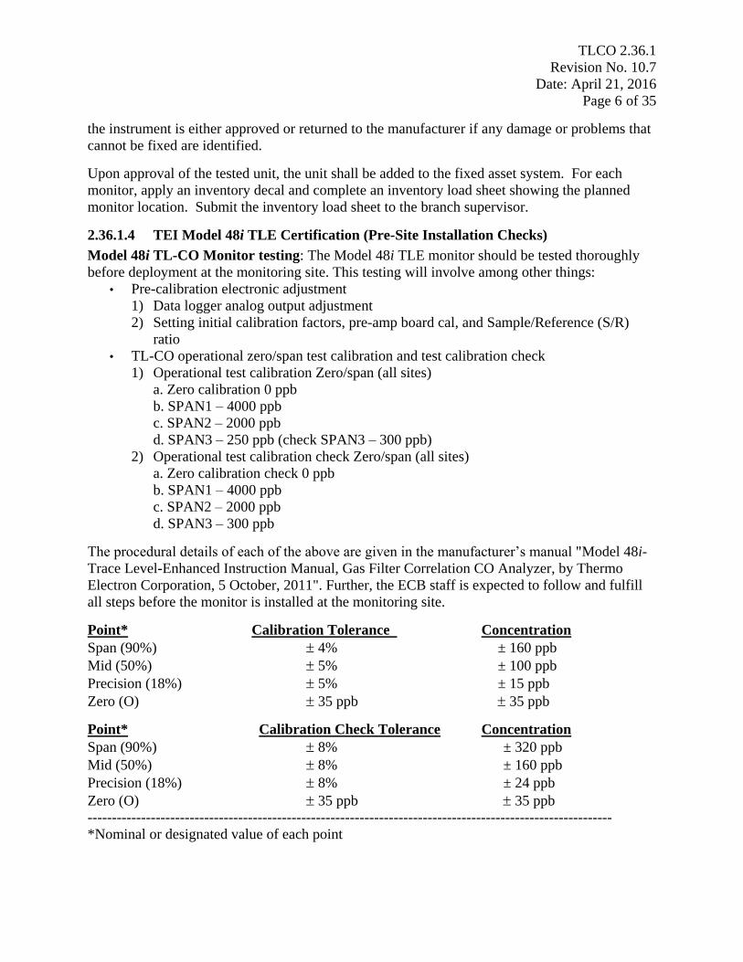
2.36.1.4 TEI Model 48i TLE Certification (Pre-Site Installation Checks)
Model 48i TL-CO Monitor testing: The Model 48i TLE monitor should be tested thoroughly
before deployment at the monitoring site. This testing will involve among other things:
• Pre-calibration electronic adjustment
1) Data logger analog output adjustment
2) Setting initial calibration factors, pre-amp board cal, and Sample/Reference (S/R)
ratio
• TL-CO operational zero/span test calibration and test calibration check
1) Operational test calibration Zero/span (all sites)
a. Zero calibration 0 ppb
b. SPAN1 – 4000 ppb
c. SPAN2 – 2000 ppb
d. SPAN3 – 250 ppb (check SPAN3 – 300 ppb)
2) Operational test calibration check Zero/span (all sites)
a. Zero calibration check 0 ppb
b. SPAN1 – 4000 ppb
c. SPAN2 – 2000 ppb
d. SPAN3 – 300 ppb
The procedural details of each of the above are given in the manufacturer’s manual "Model 48i-
Trace Level-Enhanced Instruction Manual, Gas Filter Correlation CO Analyzer, by Thermo
Electron Corporation, 5 October, 2011". Further, the ECB staff is expected to follow and fulfill
all steps before the monitor is installed at the monitoring site.
Point* Calibration Tolerance Concentration
Span (90%) 4% ± 160 ppb
Mid (50%) 5% ± 100 ppb
Precision (18%) 5% ± 15 ppb
Zero (O) 35 ppb 35 ppb
Point* Calibration Check Tolerance Concentration
Span (90%) 8% ± 320 ppb
Mid (50%) 8% ± 160 ppb
Precision (18%) 8% ± 24 ppb
Zero (O) 35 ppb 35 ppb
------------------------------------------------------------------------------------------------------------
*Nominal or designated value of each point
TLCO 2.36.1
Revision No. 10.7
Date: April 21, 2016
Page 7 of 35
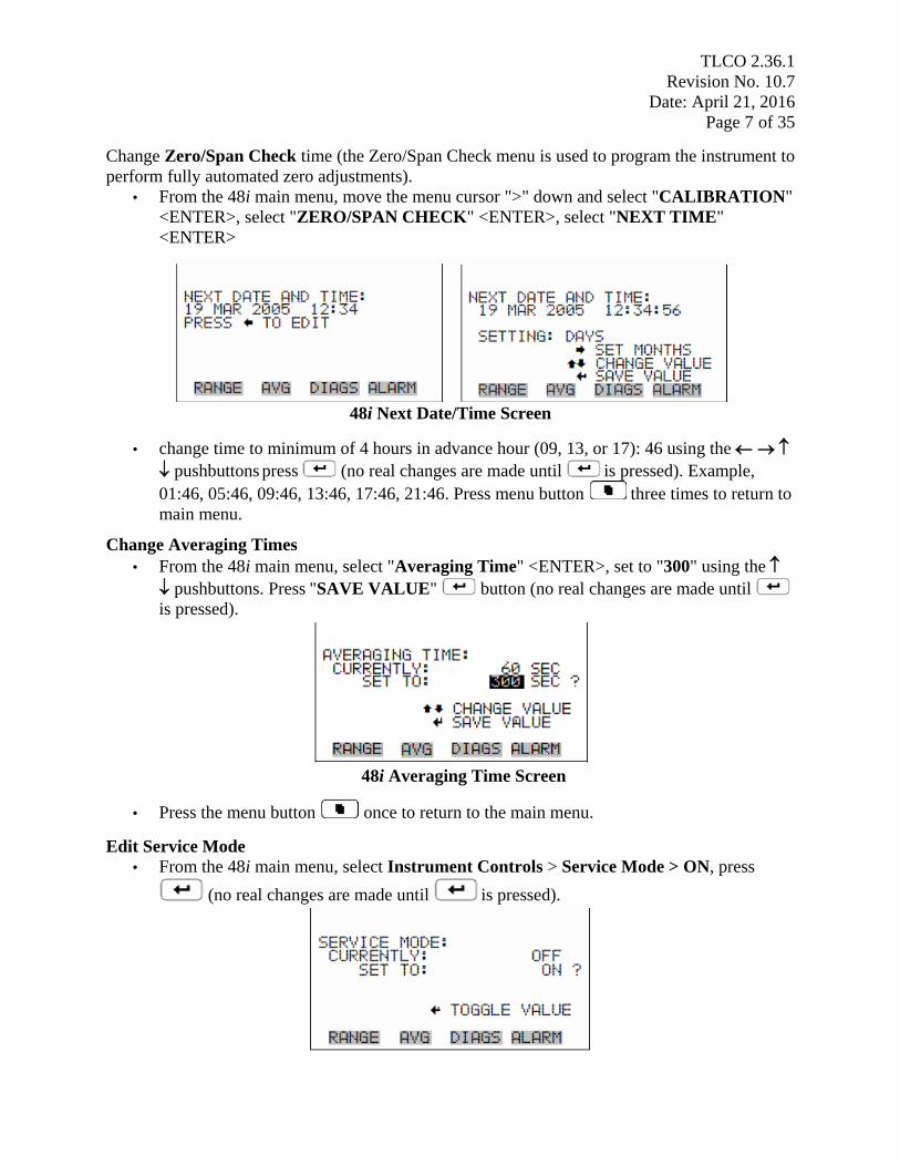
Change Zero/Span Check time (the Zero/Span Check menu is used to program the instrument to
perform fully automated zero adjustments).
• From the 48i main menu, move the menu cursor ">" down and select "CALIBRATION"
<ENTER>, select "ZERO/SPAN CHECK" <ENTER>, select "NEXT TIME"
<ENTER>
48i Next Date/Time Screen
• change time to minimum of 4 hours in advance hour (09, 13, or 17): 46 using the
pushbuttons press (no real changes are made until is pressed). Example,
01:46, 05:46, 09:46, 13:46, 17:46, 21:46. Press menu button three times to return to
main menu.
Change Averaging Times
• From the 48i main menu, select "Averaging Time" <ENTER>, set to "300" using the
pushbuttons. Press "SAVE VALUE" button (no real changes are made until
is pressed).
48i Averaging Time Screen
• Press the menu button once to return to the main menu.
Edit Service Mode
• From the 48i main menu, select Instrument Controls > Service Mode > ON, press
(no real changes are made until is pressed).

TLCO 2.36.1
Revision No. 10.7
Date: April 21, 2016
Page 8 of 35
Press menu button twice to go back to main menu.
Restore User Faults
For SPAN0 calibration, reset the calibration configuration values to the factory defaults:
• From the 48i main menu select Calibration Factors > Reset User Cal Defaults, press
Restore button, press right arrow button to confirm restore
press menu button twice to return to the main menu
Link to Logger
To begin a direct Link to Logger session, log into the AV-Trend system and use the following
procedure:
• Click on the AV-Trend icon, enter the username followed by the password, hit "OK"
• Select: "Utilities"
• Select: "Link to Logger"
• From the drop down menu select a site
• Select: "Connect"
• Select: "L", at LOGIN menu, enter password
Calibrate SPAN0
• Press{ESC}{ESC} to return to the Home Menu
• Select: "C", Configuration Menu
• Select: "C", Configure Calibration
• Select: "1", Start a Single Phase Calibration, <ENTER>
• Select: "COTCAL", <ENTER>
• Select: "SPAN0", <ENTER>
• Scroll down and highlight "Phase Duration", set to 2 hour, <ENTER>
• Scroll down and select: "Start Single Cal (NOW)", <ENTER>
Monitor Actual values
• Press {ESC} {ESC} to return to the Home Menu
• Select: "D", Real Time Display
• Select: "C", Continuous Average Report
• Select: "Show Channels", <ENTER>
• Type in parameters: "COT", <ENTER>
• Change # of flags to report from "02" to "03", <ENTER> (the "<", "D", and "C" flags
will show)
• Use decimal Positioner?: "Y", <ENTER>

TLCO 2.36.1
Revision No. 10.7
Date: April 21, 2016
Page 9 of 35
• Start continuous report: <ENTER> (this will show the minute averages as they are
calculated and keeps all values on screen).
Reset Pre Amp Board Cal
Note: SPAN0 should be running and stable for this adjustment.
From the 48i main menu, select Service > Preamp Board Cal
48i Preamp Board Cal Screen
SAMPLE: 162126 Hz (-12126) = 150000
REFERENCE: 138256 Hz (+11744) = 150000
SET TO: 51
CHANGE VALUE
In this example, at the Preamp Board Cal screen, use until the
(Sample + Reference)/2 average value reads as close to 150,000 then press to save
changes (may have to do this several times). Press menu button once to return to
the SERVICE menu.
From the 48i Service menu, select Initial S/R Ratio (SPAN0 must be running ~ 60 minutes)
48i Initial S/R Screen
the "MEASURED" reading is entered into "SET TO" reading (adjusts "CURRENTLY"
reading), Note: CO conc = approximately 0 when S/R is correctly adjusted, when finished press
menu button once to return to the SERVICE menu.
Abort SPAN Zero
• Select: "C" Configure Calibration
• Select: "C", Configuration Menu
• Select: "W", Abort Calibration
• With down arrow key, select: "COTCAL", <ENTER>

TLCO 2.36.1
Revision No. 10.7
Date: April 21, 2016
Page 10 of 35 Multi-Point Calibration
The 146C/T700U will be used to calibrate POINT 1, POINT 2, and POINT 3. During this time,
the span levels required for the calibration will be controlled via the 146C/T700U. Note: This
procedure should not be performed during the last half of the hour (i.e. after XX:30) in order to
prevent interruption in data recovery.
From the 48i SERVICE menu, select "MULTIPOINT CAL", select "CALIBRATE
POINT 1" <ENTER>
48i Multi-Point Cal Screen
SPAN1 (CALIBRATE POINT 1)
• Press{ESC}{ESC} to return to the Home Menu
• Select: "C", Configuration Menu
• Select: "C", Configure Calibration
• Select: "1", Start a Single Phase Calibration, <ENTER>
• Select: "COTCAL", <ENTER>
• Select: "SPAN1", <ENTER>
• Scroll down and highlight "Phase Duration", set to 1 hour, <ENTER>
• Scroll down and select: "Start Single Cal (NOW)", <ENTER>
Monitor Actual values
• Press {ESC} {ESC} to return to the Home Menu
• Select: "D", Real Time Display
• Select: "C", Continuous Average Report
• Select: "Show Channels", <ENTER>
• Type in parameters: "COT", <ENTER>
• Change # of flags to report from "02" to "03", <ENTER> (the "<", "D", and "C" flags
will show)
• Use decimal Positioner?: "Y", <ENTER>
• Start continuous report: <ENTER> (this will show the minute averages as they are
calculated and keeps all values on screen).
Note: Multiply PPM by 1000 to convert to PPB (data logger reading), ex. CAL GAS 1 (4.00
ppm = 4000 ppb).
Note: When span point has stabilized (~25 min):
• From the SET CAL GAS POINT 1 screen, enter CAL GAS 1 concentration (4.000 ppm,
3 significant CA figures) from 146C/T700U using pushbuttons, press (no
real changes are made until is pressed)

TLCO 2.36.1
Revision No. 10.7
Date: April 21, 2016
Page 11 of 35
CAL GAS 1 Screen
Abort SPAN1 Calibration
• Select: "C" Configure Calibration
• Select: "C", Configuration Menu
• Select: "W", Abort Calibration
• With down arrow key, select: "COTCAL", <ENTER>
SPAN2 (CALIBRATE POINT 2)
Repeat procedure to calibrate POINT 2 (CAL GAS 2, 2.000 ppm (3 significant CA figures from
146C/T700U)),
SPAN4 (CALIBRATE POINT 3)
Repeat procedure to calibrate POINT 3 (CAL GAS 3, 0.250 ppm (3 significant CA figures from
146C/T700U)),
• Press{ESC}{ESC} to return to the Home Menu
• Select: "C", Configuration Menu
• Select: "C", Configure Calibration
• Select: "1", Start a Single Phase Calibration, <ENTER>
• Select: "COTCAL", <ENTER>
• Select: "SPAN4", <ENTER>
• Scroll down and highlight "Phase Duration", set to 1 hour, <ENTER>
• Scroll down and select: "Start Single Cal (NOW)", <ENTER>
Monitor Actual values
• Press{ESC}{ESC} to return to the Home Menu
• Select: "D", Real Time Display
• Select: "C", Continuous Average Report
• Select: "Show Channels", <ENTER>
• Type in parameters: "COT", <ENTER>
• Change # of flags to report from "02" to "03", <ENTER> (the "<", "D", and "C" flags
will show)
• Use decimal Positioner?: "Y", <ENTER>
• Start continuous report: <ENTER> (this will show the minute averages as they are
calculated and keeps all values on screen).
TLCO 2.36.1
Revision No. 10.7
Date: April 21, 2016
Page 12 of 35
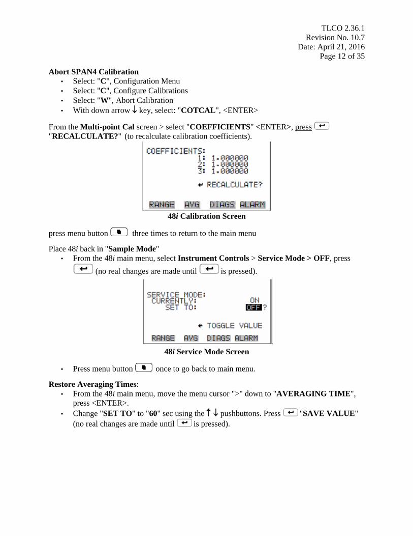
Abort SPAN4 Calibration
• Select: "C", Configuration Menu
• Select: "C", Configure Calibrations
• Select: "W", Abort Calibration
• With down arrow key, select: "COTCAL", <ENTER>
From the Multi-point Cal screen > select "COEFFICIENTS" <ENTER>, press
"RECALCULATE?" (to recalculate calibration coefficients).
48i Calibration Screen
press menu button three times to return to the main menu
Place 48i back in "Sample Mode"
• From the 48i main menu, select Instrument Controls > Service Mode > OFF, press
(no real changes are made until is pressed).
48i Service Mode Screen
• Press menu button once to go back to main menu.
Restore Averaging Times:
• From the 48i main menu, move the menu cursor ">" down to "AVERAGING TIME",
press <ENTER>.
• Change "SET TO" to "60" sec using the pushbuttons. Press "SAVE VALUE"
(no real changes are made until is pressed).

TLCO 2.36.1
Revision No. 10.7
Date: April 21, 2016
Page 13 of 35
48i Averaging Time Screen
• Press the menu button once to return to the main menu.
Verification - Zero/Span Points
Span Zero Check Procedure
• Press {ESC} {ESC} to return to the Home Menu
• Select: "C", Configuration Menu
• Select: "C", Configure Calibration
• Select: "1", Start a Single Phase Calibration, <ENTER>
• Select: "COTCAL", <ENTER>
• Select: "SPAN0", <ENTER>
• Scroll down and highlight " Phase Duration", set to 1 hour, <ENTER>
• Scroll down and select: "Start Single Cal (NOW)", <ENTER>
Monitor Actual values
• Press{ESC}{ESC} to return to the Home Menu
• Select: "D", Real Time Display
• Select: "C", Continuous Average Report
• Type in parameter: "COT", <ENTER>
• Change # of flags to report from "02" to "03", <ENTER> (the "<", "D", and "C" flags
will show)
• Use decimal Positioner?: "Y", <ENTER>
• Start continuous report: <ENTER> (this will show the minute averages as they are
calculated and keeps all values on screen).
• Abort SPAN0 "C", "C", "W", "COTCAL" <ENTER>
Span Check Procedure
• {ESC} {ESC} to return to the Home Menu
• Select: "C", Configuration Menu
• Select: "C", Configure Calibration
• Select: "1", Start a Single Phase Calibration, <ENTER>
• Select: "COTCAL", <ENTER>
• Select: "SPAN1", <ENTER>
• Scroll down and highlight "Phase Duration", set to 1 hour, <ENTER>
• Scroll down and select: "Start Single Cal (NOW)", <ENTER>
TLCO 2.36.1
Revision No. 10.7
Date: April 21, 2016
Page 14 of 35 Monitor Actual values
• Press {ESC} {ESC} to return to the Home Menu
• Select: "D", Real Time Display
• Select: "C", Continuous Average Report
• Type in parameter: "COT", <ENTER>
• Change # of flags to report from "02" to "03", <ENTER> (the "<", "D", and "C" flags
will show)
• Use decimal Positioner?: "Y", <ENTER>
• Start continuous report: <ENTER> (this will show the minute averages as they are
calculated and keeps all values on screen).
• Abort SPAN1 ("C", "C", "W","COTCAL" <ENTER>)
• Check SPAN2 (2000 ppb) and SPAN3 (300 ppb) the same way
• Abort SPAN3 ("C", "C", "W","COTCAL" <ENTER>)
Method Detection Limit (MDL)
The method detection limit (MDL) refers to the lowest concentration of a substance that can be
reliably determined by a given procedure (Section 2.36.1.11).
Lower Detection Limit (LDL)
The LDL is the minimum pollutant concentration that produces a signal of twice the noise level.
To estimate the LDL, zero air is sampled and the noise level of the CO readings is determined
according to 40 CFR 53.23(b). The vendor-specified LDL (instrument manual) for the most
sensitive range of high sensitivity CO analyzers should be 0.040 ppm (40 ppb) or lower, over an
averaging time of no more than 5 minutes.
Linear Range
The linear range of each high sensitivity CO analyzer should extend from approximately 0.040
ppm to at least 5 ppm. A copy of the linear range will be retained with the instrument
logbook/file.
Zero/Span Drift
Zero drift is defined as the change in response to zero pollutant concentration, over 12- and 24-
hour periods of continuous unadjusted operation. Span drift is defined as the percent change in
response to an upscale pollutant concentration over a 24-hour period of continuous unadjusted
operation. Zero and span drift specifications should be obtained from the vendor prior to putting
a high sensitivity CO analyzer into service. Such CO analyzers should have 12- and 24-hour zero
drift less than 0.100 ppm, and should have a span drift of less than ±1 percent of the full-scale
measurement range of the analyzer per 24 hours. Zero tests should be performed with the internal
zero engaged. It is suggested that the zero trap of the analyzer be initially and periodically
(annually) evaluated for efficiency or if the operator suspects a problem with the zero trap. A
suggested means of confirming the functionality of the zero trap is to sample calibration air
spiked with 1 to 2 ppm CO during the zero cycle, and review results for the automatic zeroing
TLCO 2.36.1
Revision No. 10.7
Date: April 21, 2016
Page 15 of 35
periods. This approach tests the key components of the zeroing/drying system and should meet
the vendor-specified zero drift criterion. Record the zero/span test observations in the instrument
logbook/file.
Interferences and Sources of Bias
Preventing interferences or biases is crucial to the accurate measurement of low ambient levels
of CO. Record any interferences and sources of bias observations in the instrument logbook/file.
a. Positive Interferences
Gas filter correlation (GFC) CO analyzers determine CO concentration by measuring the amount
of light that is absorbed at a select wavelength (4.7µm) as it passes through a sample cell
containing CO. Any other gas in the air sample that also absorbs at those wavelengths could
present an interference that result in an inaccurate determination of CO concentration. Removal
of potential interferences must be done selectively such that these interferences are completely
removed without affecting the CO concentration. To achieve this goal, high sensitivity CO
analyzers are equipped with a permeation tube or Nafion™ drier that selectively removes water
vapor from the sample gas without removing CO. Record any positive interference observations
in the instrument logbook/file.
b. Negative Interferences and Biases
High sensitivity CO analyzers are equipped with a solenoid switching system to draw sample air
into a heated internal scrubber that converts all CO to CO2. The analyzer then measures the light
absorption of this CO-free air and uses that light intensity to establish the zero reading. However,
any CO that is not converted to CO2 would remain in the sample gas and decrease the light
intensity (i.e., absorb the light) used to establish the zero reading, resulting in an artificially high
zero reading and a negative bias when measuring the CO in ambient air. To avoid this situation,
it is important that the heated scrubber be maintained at the manufacturer’s recommended
temperature. Zero air and sample air readings should be within ±0.010 ppm (10 ppb), and
scrubber efficiency should be >99%. Record any negative interference or bias observations in the
instrument logbook/file.
Detector Stability
The temperature of the detector in a high sensitivity CO analyzer must remain stable in order to
allow for ppb sensitivity. Commercial high sensitivity CO analyzers provide a display of the
detector temperature. This temperature should be checked periodically for compliance with the
vendor’s required temperature setting. Bench temperature should be checked both with and
without the zero scrubber engaged, to ensure that scrubber effluent does not cause heating of the
optical bench. Record the detector temperature checks in the instrument logbook/file.
Verification of Component Performance
The following Test mode parameter ranges are allowed in the TEI 48i TLE Analyzer:
TLCO 2.36.1
Revision No. 10.7
Date: April 21, 2016
Page 16 of 35
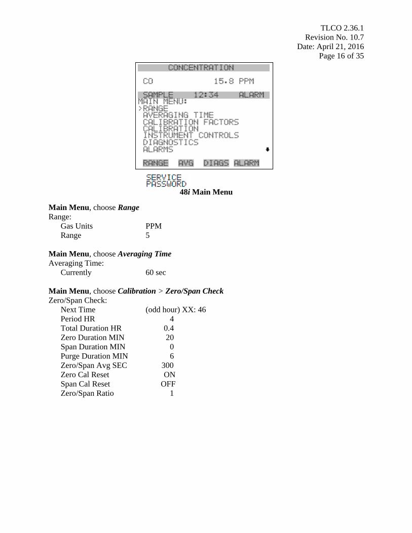
48i Main Menu
Main Menu, choose Range
Range:
Gas Units PPM
Range 5
Main Menu, choose Averaging Time
Averaging Time:
Currently 60 sec
Main Menu, choose Calibration > Zero/Span Check
Zero/Span Check:
Next Time (odd hour) XX: 46
Period HR 4
Total Duration HR 0.4
Zero Duration MIN 20
Span Duration MIN 0
Purge Duration MIN 6
Zero/Span Avg SEC 300
Zero Cal Reset ON
Span Cal Reset OFF
Zero/Span Ratio 1

TLCO 2.36.1
Revision No. 10.7
Date: April 21, 2016
Page 17 of 35
48i Instrument Controls Menu
Main Menu, choose Instrument Controls Menu> Communication Settings>Baud Rate
Baud rate:
Baud rate 9600
Main Menu, choose Instrument Controls Menu> Communication Settings> Instrument ID
Instrument ID:
Instrument ID 48
Main Menu, choose Instrument Controls Menu> Communication Settings> Communication
Protocol
Communication Protocol:
Communication Protocol CLINK
Main Menu, choose Instrument Controls Menu> Communication Settings> RS 232/RS-485
RS 232/RS-485:
RS 232/RS-485 Selection RS 232
Main Menu, choose Instrument Controls > I/O Configuration> Output Relay Settings
Output Relay Settings:
1 NOP Zero Mode
2 NOP Purge Mode
3 NOP UNITS
4 NOP GEN ALARM
5 NOP NONE
6 NOP NONE
7 NOP NONE
Main Menu, choose Instrument Controls > I/O Configuration> Digital Input Relay Settings
Digital Input Setting:
1 NOP Span Mode
2 NOP NONE
3 NOP NONE
4 NOP NONE
5 NOP NONE
6 NOP NONE

TLCO 2.36.1
Revision No. 10.7
Date: April 21, 2016
Page 18 of 35 7 NOP NONE
Main Menu, choose Instrument Controls > I/O Configuration >Analog Output Config >
Voltage Channel 1 > RANGE
Analog Output Config:
Select Range 0-10v
Set Minimum Value 0%
Set Maximum Value 100%
Choose Signal To Output CO
Main Menu, choose Instrument Controls> Temperature Compensation
Temperature Compensation:
Comp Temp 42.3
Currently ON
Main Menu, choose Instrument Controls> Pressure Compensation
Pressure Compensation
Comp Pres displays the current optical bench pressure.
Currently ON
Main Menu, choose Instrument Controls> Service Mode
Service Mode
Currently OFF
48i Diagnostics Menu
Main Menu, choose Diagnostics > Voltages> Motherboard
Motherboard Voltages:
3.3 SUPPLY 3.3 V
5.0 SUPPLY 5.0 V
15.0 SUPPLY 15.0 V
24.0 SUPPLY 24.1 V
TLCO 2.36.1
Revision No. 10.7
Date: April 21, 2016
Page 19 of 35 -3.3 SUPPLY -3.3 V
Main Menu, choose Diagnostics > Interface Board Voltages
Interface Board Voltages:
3.3 SUPPLY 3:3 V
5.0 SUPPLY 5.0 V
15.0 SUPPLY 15.0 V
24.0 SUPPLY 24.1 V
-15.0 SUPPLY -15.0 V
18.0 IR SUPPLY 18.0 V
18.0 MOT SUPPLY 18.0 V
Bias SUPPLY -109.9 V
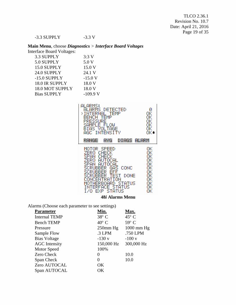
48i Alarms Menu
Alarms (Choose each parameter to see settings)
Parameter Min. Max.
Internal TEMP 38 C 45 C
Bench TEMP 40 C 59 C
Pressure 250mm Hg 1000 mm Hg
Sample Flow .3 LPM .750 LPM
Bias Voltage -130 v -100 v
AGC Intensity 150,000 Hz 300,000 Hz
Motor Speed 100%
Zero Check 0 10.0
Span Check 0 10.0
Zero AUTOCAL OK
Span AUTOCAL OK

TLCO 2.36.1
Revision No. 10.7
Date: April 21, 2016
Page 20 of 35 Scrubber Gas Conc 5 100
Scrubber EFF 95 101
Scrubber TEST DONE OK
Concentration 0 1000
Motherboard Status OK
Interface Status OK
I/O Exp Status OK
Note: Adjust the operational parameters as necessary if outside to these ranges. If adjustments
are performed the stability of the adjusted parameter(s) must be evaluated and recorded prior to
proceeding.
The ECB is responsible for setting the operational parameters of each TEI 48i TLE as listed
above. Primary Standard operation outside of these settings and limits is non-compliant with the
NC QA/SOP for ambient air carbon monoxide monitoring and the data will be invalidated.
Yearly and prior to installation at the monitoring site, the ECB must evaluate the condition
and performance of each TEI Model 48i TLE. The results of the evaluation, findings, and
all adjustments are entered into the carbon monoxide standard specific site logbook, dated,
and initialed.
• Perform any scheduled approved preventative maintenance procedures and or system
enhancements.
• Visually inspect both cells for contamination and clean if necessary. If cells are dirty
investigate causes of contamination and correct per manufacturer’s recommendations.
• If the Gas Filter Wheel is changed;
a. Connect zero air to monitor and equilibrate for 2 hours.
b. Set Averaging Time to 300 seconds; from the 48i main menu, select "CALIBRATION",
select "ZERO/SPAN CHECK", select "ZERO/SPAN AVERAGING TIME", use
the pushbuttons to change SET TO value to "300", press to save changes.
c. Set autozero/span check ahead four hours; from the 48i main menu, select
"CALIBRATION", select "ZERO/SPAN CHECK". Change "Next Time" to minimum
of 4 hours in advance odd hour (09, 13 or 17): 46 using the pushbuttons press
(no real changes are made until is pressed). Example, 01:46, 05:46, 09:46,
13:46, 17:46, 21:46.
d. Reset Calibration Factors to defaults, from the 48i main menu, choose Calibration
Factors
BKG 0.0
COEF 1.000
Press Reset user Cal defaults.
e. Place 48i in Service Mode.
From the 48i main menu, select Instrument Controls > select Service Mode
Set to "ON"
f. Reset Pre Amp Board Cal
Note: SPAN zero must be running and stable for this adjustment.
From the 48i main menu, select Service > Preamp Calibration

TLCO 2.36.1
Revision No. 10.7
Date: April 21, 2016
Page 21 of 35 SAMPLE: 127807 Hz
REFERENCE: 148256 Hz
SET TO: 51
CHANGE VALUE
SAMPLE: 162126 Hz (-12126) = 150000
REFERENCE: 138256 Hz (+11744) = 150000
In this example, At the Preamp Board Cal screen, use until the
(Sample + Reference)/2 average value reads as close to 150,000 then press
to save changes (may have to do this several times).
g. Set Initial S/R Ratio to "Measured".
From the 48i main menu, select Service, select Initial S/R Ratio
CURRENTLY: 1.079620
MEASURED: 1.130966
SET TO:
MEASURED reading entered into SET TO, adjusts CURRENTLY reading.
h. Set Averaging Time to 60 seconds; from the 48i main menu, select CALIBRATION,
select ZERO/SPAN CHECK, select ZERO/SPAN AVERAGING TIME, use the
pushbuttons to change SET TO value to "60", press to save changes.
i. Remove 48i from service mode. From the 48i main menu, select Instrument
Controls > Service Mode > OFF, press (no real changes are made until is
pressed).
• Perform a Sample Route thru Solenoid, Span / Zero Air Route thru Solenoid and a
Kicker leak test.
Sample Route thru Solenoid:
1. From the 48i main menu, move menu cursor down, select DIAGNOSTICS, select
"Pressure" (to display the Pressure screen).
2. Disconnect the sample input line at the filter holder inlet and cap with a cap. It should
take less than three minutes from the time the inlet is plugged to the time the pressure
reading drops below 250 mmHg. If not, check to see that all fittings are tight and that
none of the input lines are cracked or broken. If no leak is found, remove cap and
reconnect sample line. Press menu button twice to return to the main menu.
Span / Zero Air Route thru Solenoid:
1. From the 48i front panel, press (RUN) button until "ZERO" appears in the status
line.
2. From the 48i main menu, move menu cursor down, select DIAGNOSTICS, select
"Pressure" (to display the Pressure screen).
3. Disconnect the probe line before the "T" fitting and cap it where probe line was removed
from with a cap, remove span in line, cap with metal cap nut. It should take less than
three minutes from the time the inlet is plugged to the time the pressure reading drops
below 250 mmHg. If not, check to see that all fittings are tight and that none of the input

TLCO 2.36.1
Revision No. 10.7
Date: April 21, 2016
Page 22 of 35
lines are cracked or broken. If no leak is found, remove cap and reconnect probe line.
Press menu button twice to return to the main menu.
Kicker Leak Check:
Note: Kicker leak check is performed after a filter change.
1. Change schedule on the 48i to do an auto zero and let it start.
2. Cap off the filter holder inlet with a plug.
3. From the 48i main menu, move menu cursor down, select DIAGNOSTICS, select
"Pressure" (to display the Pressure screen).
5. It should take less than three minutes from the time the inlet is plugged to the time the
pressure reading drops below 250 mmHg. If not, check to see that all fittings are tight and
that none of the inlet lines are cracked or broken. If no leak is found, remove cap and
reconnect inlet line. If the leak test fails, investigate causes and correct per
manufacturer’s recommendations.
• Verify and adjust, if necessary, the Model 48i TLE operational parameters. If system fails to
achieve required operational parameters investigate causes and correct per manufacturer’s
recommendations.
• Connect the zero air supply and the CO concentration standard to the Model 146C/T700U
calibrator and the Model 48i TLE analyzer at atmospheric pressure and per manufacturer
instructions if necessary. In order to satisfy all EPA requirements for precision and level 1
span checks (see 40 CFR 58, Appendix A), it is recommended that the filter be installed
between the sample–span solenoid and the optical bench.
• Activate the Zero (0 ppm) events on the data logger and allow the readings to stabilize on the
Model 48i TLE analyzer.
• Activate the Span 1 (4.000 ppm) event on the data logger and allow the readings to stabilize
on the Model 48i TLE analyzer.
• Activate the Span 2 (2.000 ppm) and Span 3 (0.300 ppm) points. Allow readings to stabilize
for 5 minutes for each of the verification points.
2.36.1.5 Calibration Standards and System
Calibration Standards
The ECB shall procure calibration standards for the Ambient Monitoring Section. Primary
Carbon Monoxide Standards are used to calibrate and evaluate the ongoing calibration checks
and audit performance of the carbon monoxide monitors at each site. The primary CO standards
used must be certified, commercially prepared compressed gas standards with a certified
accuracy of no worse than ±2 percent. Standards in the concentration range of ~200 ppm are
suitable choices for dilution to prepare low concentration calibration mixtures.
a. Extreme care must be taken to ensure compatibility for all components. Flow rates and
concentration outputs must meet the requirements of the monitor.
b. All primary standard calibration gases must be referenced to a National Bureau of Standards

TLCO 2.36.1
Revision No. 10.7
Date: April 21, 2016
Page 23 of 35
(NBS) carbon monoxide in Air Standard Reference Material (SRM) or an NBS/EPA approved gas
manufacturer’s Certified Reference Material (CRM). A written statement of certification should be
obtained which provides the following:
a. a brief description of the certification procedure,
b. cylinder numbers,
c. cylinder gas concentrations,
d. replicate analysis data,
e. balance gas used,
f. NBS, SRM numbers used as standards, and
g. last analysis date.
A copy of this certification should be available to users and should be kept on file at the ECB.
c. Calibration standards will be replaced every 8 years for 500 ppb to 10 percent CO in air
standard (This time period is allowed because CO is very stable as shown by repeated analysis of
the same cylinder and in accordance with 40CFR50 App. C.3.1. In actual practice most
cylinders may be expended sooner).
d. No cylinder gas should be used below a cylinder pressure of 200 psig as shown by the
cylinder gas regulator.
e. Each CO span gas cylinder shall contain the following minimum traceability information on
a label or tag affixed to the cylinder or valve:
a. the concentration of cylinder gas,
b. the last analysis date,
c. the expiration date,
d. the initials of the person performing the analysis,
e. cylinder number, and
f. balance gas.
TEI 146C Calibrator
The 48i TLE analyzer is calibrated using a TEI 146C Calibrator, which must have flows certified
by ECB and traceable to a primary standard according to the requirements in the QA/SOP 2.3.4
TEI 146C Calibrator. These systems allow for accurate dilution of CO standard gases from high
concentration (usually ~200 ppm) to low ambient working standard concentrations (e.g., from
0.040 to 0.500 ppm).
It is highly important when purchasing a mass flow controlled (MFC) calibrator that it meet the
40 CFR 50 requirements of ±2 percent flow accuracy, and that the calibrations of both MFC
channels be checked periodically and recorded in the 146C logbook using a NIST traceable flow
standard.
T700U Calibrator
The 48i TLE analyzer is calibrated using a T-API T700U Calibrator, which must have flows

TLCO 2.36.1
Revision No. 10.7
Date: April 21, 2016
Page 24 of 35
certified by ECB and traceable to a primary standard according to the requirements in the
QA/SOP 2.3.7 T-API T700U Calibrator. The T-API T700U Dynamic Dilution Calibrator
supplies precise levels of sulfur dioxide, sulfate, nitric oxide, and nitrogen dioxide. The gas
levels are used to calibrate instruments that perform zero, precision and Level 1 span checks,
audits, and multipoint calibration of these gases. For detailed operational procedures and
maintenance procedures, consult the Model T700U Instruction Manual ("Operational Manual,
Model T700 Dynamic Dilution Calibrator, 6 October 2010" and "Model T700U Calibrator
(Addendum to T700 Manual), 6 October 2010, 06876 Rev A").
Teledyne Model 701 Zero Air Generator
The T-API Model 701 Zero Air Generator is a pure air generator system that is capable of
continuous delivery of up to 20 standard liters per minute (SLPM), 30 pounds per square inch
(PSI) of dry, contaminant-free air. The air is suitable for use as: a zero reference calibration gas,
ultra-pure combustion air for flame ionization detector, and service air for pneumatically
operated valves. The system is capable of delivering air free from water vapor, particulates,
sulfur dioxide (SO2), Hydrogen Sulfide (H2S), Oxides of Nitrogen (NO), Nitrogen Dioxide
(NO2), Ozone (O3), and Carbon Monoxide (CO).
Model 701 Zero Air Generator Checks:
• The pollution scrubber/converter media should be replaced yearly by the ECB.
• Verify that the delivery pressure is set to 30 psi. (If the delivery pressure is outside of ± 2 psi
range, adjust the pressure using pressure adjust control knob.)
• Check the drain from the air generator.
2.36.1.6 Site Monitor Operation / Verification (Site Installation)
After the regional office has obtained permission to use a site from the site owner, and after
DAQ Ambient Monitoring Project and Procedures Supervisor and ECB have approved the site,
the Electronics and Calibration Branch will install the monitor and its appurtenances. Electrical
circuits should be dedicated, properly sized and labeled prior to the installation of the monitor
equipment. Inspect the site for integrity and safety.
The ECB Supervisor is responsible for the installation of all State operated ambient air carbon
monoxide monitoring sites across the state each year. For seasonal sites, the sites are required to
be setup prior to the start date of the EPA approved carbon monoxide monitoring season. Consult
the ECB Supervisor for when startup dates are for the instruments being readied for the field
The installation of the carbon monoxide monitoring sites includes:
• Certified Primary "CO" Gas Cylinder Standard
• Thermo Environmental (TEI) Model 48i TLE Carbon Monoxide Monitor
• Thermo Environmental (TEI) Model 146C Gas Calibrator (QA/SOP 2.3.4)
• T-API T700U Dynamic Gas Calibrator (QA/SOP 2.3.7)
• T-API Model 701 Zero Air Pak (QA/SOP 2.3.5)
• Pretreated Teflon Sampling Line
• Computer/ESC 8832 Data Logger/Wireless Modem System/Ethernet

TLCO 2.36.1
Revision No. 10.7
Date: April 21, 2016
Page 25 of 35
The monitoring site installation also may include additional items such as the air conditioning
unit and heater but these components generally remain at the site year round. Following the
installation of all components of the carbon monoxide monitoring system, the performance of all
components is verified as the final step of the site installation.
Verification of Component Performance
A. Equipment Specifications
The following Test mode parameter ranges are allowed for the TEI 48i TLE Analyzer:
Parameter Min. Max.
Internal TEMP 38 C 45 C
Bench TEMP 40 C 59C
Pressure 250mm Hg 1000 mm Hg
Flow .3 LPM .750 LPM
Sample/Ref Ratio 1.14 1.18
Bias Voltage -130 v 115 v
AGC Intensity 150,000 Hz 300,000 Hz
Motor Speed 100%
Note: Adjust the operational parameters as necessary if outside to these ranges. If adjustments
are performed, the stability of the adjusted parameter (s) must be evaluated prior to proceeding.
If the results of the adjustments do not fall within the limits, consult manufacturer until these are
met.
The ECB is responsible for setting and recording in logbook the operational parameters of each
TEI 48i TLE as listed above. Primary Standard operation outside of these settings and limits is
non-compliant with the NC QA/SOP for ambient air carbon monoxide monitoring and the data
will be invalidated.
B. Equipment Checks
WARNING: Do not plug in the monitor, modem, data logger, and computer until all
cables are connected. ELECTRICAL SHOCK AND/OR EQUIPMENT DAMAGE MAY
OCCUR OTHERWISE.
• Connect the TEI Model 48i TLE, power up, and allow warming up for 1 hour.
• Perform a leak check as per Instrument Manual, Section 5. If leak check fails, investigate
causes and correct per manufacturer’s recommendations.
• Bleed cylinder regulator:
Close line valve, fill regulator by opening cylinder tank valve,
Close cylinder tank valve,
Loosen cylinder line fitting at 146C/T700U,
Open line valve – hear gas escape – don’t lose all pressure,
Close line valve,
Fill regulator by opening cylinder tank valve,
Close cylinder tank valve,
Open line valve – hear gas escape – don’t lose all pressure,
Close line valve,
TLCO 2.36.1
Revision No. 10.7
Date: April 21, 2016
Page 26 of 35 Fill regulator by opening tank cylinder valve,
Close cylinder tank valve,
Open line value – hear gas escape – tighten gas line fitting at 146C/T700U,
Open cylinder valve and line valve fully open,
Check for leaks,
Cylinder pressure set to 30 psi,
• Verify and adjust, if necessary, the Model 48i TLE operational parameters. If system fails to
achieve required operational parameters as listed in "Verification of Component
Performance A. Equipment Specifications" (see pg. 25), investigate causes and correct per
manufacturer’s recommendations until met.
• Conduct operational checks for zero / span solenoid and diagnostics / alarms events.
• Configure the data logger to acquire 48i diagnostics "Flow" and "Intensity".
• The times for the data logger, AV-Trend, and computer must be EASTERN STANDARD
TIME. Additionally, they must have the same time and be synched to the NIST time provider
in Colorado (+ 1 minute). A task can be set up in AV-Trend to ensure that the times are
synchronized. This task is accomplished by clicking on the date and time in the lower right
corner of the computer screen. Select "Change date and time settings". Select "Internet
Time" tab, and "Change settings". Check the box that states "Synchronize with an Internet
time server". From the Server drop down menu, select "time.nist.gov". Press "Update
Now". Select "OK", twice to exit.
If the data logger time is not within 1 minute of NIST time but it matches the computer time,
then there is a problem with the computer time. Either the computer is not synchronizing
properly with the NIST time or the clock is drifting too much and needs to be synchronized
more often or the computer needs to be replaced.
If the data logger time is not within 1 minute of NIST time and it does not match the
computer time and the computer matches NIST time, then there is a problem with the
synchronization of the data logger time with the computer.
Sources for getting the correct time:
1. Call the NIST Colorado time @ (303) 499-7111.
2. Correct time from cell phone.
3. Setting a watch to the correct time website, http://tycho.usno.navy.mil/ , within 24 hours of
visiting the site.
• Connect the zero air supply and the CO concentration standard to the Model 146C/T700U
calibrator and the Model 48i TLE analyzer at atmospheric pressure and per manufacturer
instructions if necessary. In order to satisfy all EPA requirements for precision and level 1
span checks (see 40 CFR 58, Appendix A), it is recommended that the filter be installed
between the sample–span solenoid and the optical bench.
• Activate the Span Zero (0 ppm) event on the data logger and allow the readings to stabilize
on the Model 48i TLE analyzer. Abort the Span Zero event.
• Activate the Span 1 (4.000 ppm) event and allow the readings to stabilize. Abort the Span 1
event.

TLCO 2.36.1
Revision No. 10.7
Date: April 21, 2016
Page 27 of 35
• Activate the Span 2 (2.000 ppm) and Span 3 (0.300 ppm) points. Allow the readings to
stabilize for 5 minutes for each of the points. Abort the Span 3 event.
• Verify and adjust, if necessary, the Model 48i TLE operational parameters. If system fails to
achieve required operational parameters investigate causes and correct per manufacturer’s
recommendations.
• Check that the heat tape is working and the insulation is adequate.
• Leave channel down for calibration.
C. Equipment Identification
Fixed Asset System (FAS) numbers for the Model 48i TLE Carbon Monoxide Monitor, the
Model 146C Gas Calibrator, the Model T700U Gas Calibrator, the Model 701 Zero Air Pak, data
logger and computer will be attached on monitor and documented / logged on the 109 Form and
record kept in appropriate ECB file.
D. Teflon Sampling Line
The Teflon sampling line is a 3/8" OD ¼" ID virgin continuous piece of sample tubing that runs
from the back of the particulate filter holder on the TEI 48i TLE monitor to the inverted funnel
on the outside of the monitoring shelter. Care should be taken to ensure that dirty, wet, or
incompatible materials in the sample lines do not contaminate the sample. The inlet line should
be wrapped with removable polyurethane insulation and if humidity problems occur, wrapped
with heat tape or similar device to maintain 100° F to 120° F, in order to prevent condensation.
The length of the tubing should be held to a minimum. For best results the tubing between the
inlet and the analyzer should be less than ten (10) feet. The sampling line is replaced
whenever damage or contamination is observed or every two (2) years. For sites that operate
continuously, the probe and funnel will be replaced during even years (i.e., 2006, 2008, etc.).
Sample lines should be capped / plugged when not in use.
E. Zero Air Pak
The Model 701 Zero Air Pak provides dried scrubbed ambient air to the calibrator. The ambient
air first passes through two silica gel cartridges to remove moisture. Replacing the silica gel is
the responsibility of the ECB for the site(s).
Annually
Replace Model 701 zero air pack annually with a certified zero air pack or:
Replace CO-CO2. Shake out the catalyst beads and dispose. No special disposal methods
required. Pour in new catalyst to 1/2" from the top of the bores. Tap the cartridge sides gently to
settle the beads and top up to the 1/2" level.
Replace the charcoal. Refill the canister with fresh charcoal, up to 3/8" to 1/4" from the top.
Rap the sides of the canister gently to settle the charcoal and add more as necessary.
Replace the carulite. The procedure is the same as replacing charcoal.
TLCO 2.36.1
Revision No. 10.7
Date: April 21, 2016
Page 28 of 35
Replace the NO -NO2 scrubber. This procedure is identical to the charcoal scrubber
replacement procedure except that the canister should be refilled with Purafil®.
Record the chemical change(s) in the instrument logbook/file. If chemicals are changed in the
site zero air pack, the zero air pack must be conditioned 24 hours before use. The performance
of the zero air pack must also be confirmed using the procedures in QA/SOP 2.3.5 (NCore only).
F. Computer Data Logger System and Modem
1. Site Polling - manually poll the data logger to review data and remove flags if needed.
2. Remote Polling - check to make sure the wireless modem is in working order.
3. Turn off computer screen. Note: DO NOT close the AV-Trend software, DO NOT turn off
the computer.
G. Temperature Controlled Monitoring Shelter
The monitor must be installed in a building where the room temperature extremes do not exceed
20°C to 30°C (68°F to 86°F). Connect all heaters and air conditioning equipment power cords to
an 115v AC, 60 Hz grounded receptacle. Check to make sure the equipment is in working order.
Remove the air conditioning filter and clean if necessary. Document this activity.
2.36.1.7 Preventive Maintenance
Routine preventive maintenance procedures should be in place to prevent downtime and data
loss. Management and field operators should jointly develop their preventive maintenance
program. A program designed by persons unfamiliar with analyzer operations may include
unnecessary items or omit mandatory ones. Several factors linked to shelter and sampling design
can contribute to data loss. CO values can be low if the sample probe and lines are dirty, cracked,
or leaky. FEP and PTFE sampling lines should be replaced every two years. Teflon® filters used
in the sampling train to remove fine particles should be replaced at least once per month, but may
need to be replaced as often as every week, depending on the condition of the filter and the
particulate loading around the monitoring site.
Table 1 illustrates items that the ECB will record in their preventive maintenance monitor
logbook for TEI48i CO monitoring.
Table 1
Item Schedule
Inspect internal, external tubing; replace if
necessary
Annually
Scrubber Efficiency Test Annually
Replace IR source Annually
Rebuild or replace pump Every two years, or as needed
Clean optic bench As needed
Replace wheel motor As needed
Replace correlation wheel As needed

TLCO 2.36.1
Revision No. 10.7
Date: April 21, 2016
Page 29 of 35
The preventive maintenance plan also includes the task descriptions illustrated below. Record the
results of the tasks in the monitor logbook.
1. Because the analyzer pneumatic system requires so much preventive maintenance, the
tubing, solenoids, and pump are inspected regularly. Cracked tubing or loose fittings can
cause the instrument to analyze room air rather than ambient air and lead to invalid data. A
faulty pump can also cause problems with pneumatic systems. When a low flow rate or failed
leak test occurs, the pump is failing and should be either repaired or replaced.
2. Check the instrument for vibration. When pumps get old, they sometimes will vibrate more
than is normal. If this occurs, it can cause cracks if the tubing is touching another surface.
Consult the analyzer operations manual for complete details on operation and maintenance.
3. Scrubber Efficiency Test (NCore - Annual): The Scrubber Test screen allows the user to
initiate a scrubber efficiency test, or to stop a test that is currently in progress. Typically, the
efficiency test should run for at least 20 minutes. When the efficiency test is initiated, a timer
is started and the efficiency test will automatically shut off. The scrubber test results allow
the user to view the current CO reading, the span gas concentration, and the scrubber
effectiveness, expressed as a percent efficiency.
146C Calibrator
1. Set autozero/span check ahead four hours; from the 48i main menu, press
"CALIBRATION", select "ZERO/SPAN CHECK", select ZERO/SPAN
AVERAGING SECONDS. Change "Next Time" to minimum of 4 hours in advance
odd hour (09, 13 or 17): 46 using the pushbuttons press (no real changes
are made until is pressed). Example, 01:46, 05:46, 09:46, 13:46, 17:46, 21:46.
2. On the 146C set GAS B Span 1 concentration PPM and appropriate flows to achieve 5.5
ppm.
3. Connect Teflon line to filter holder inlet from 146C output.
4. Place 146C in LOCAL mode.
5. Start COT B span 1 on 146C and allow TEI 48i to equilibrate.
6. Place 48i in Service mode.
7. From the TEI 48i main menu, choose Service > Scrubber Test start
a. Test phase: SPAN CHK (10 min)
b. Test phase: SCRUBBER (10 min), end with % EFFICIENCY
SCRUBBER EFFICIENCY:
TEST PHASE: SCRUBBER
TEST GAS CONC: 5.498
CURRENT CONC: 0.000
% EFFICIENCY 0.0%
When test is completed, purge 48i 10 minutes, set 146C to REMOTE, GAS B Span 1 flow
and concentration to 4ppm on the 146C. Remove the 48i from SERVICE mode.
8. Re-connect the Teflon line to Span in on 48i from 146C output.

TLCO 2.36.1
Revision No. 10.7
Date: April 21, 2016
Page 30 of 35
Acceptable efficiency for the scrubber test is 95 – 101%. Contact instrument manufacturer if
efficiency test is outside these ranges. The efficiency test is performed yearly in addition
to the Accuracy Audits. Record the results of the efficiency test on the AQ 109 form and
instrument logbook.
T700U Calibrator
1. Set autozero/span check ahead four hours; from the 48i main menu, select
CALIBRATION, select ZERO/SPAN CHECK, select ZERO/SPAN AVERAGING
SECONDS. Change "Next Time" to minimum of 4 hours in advance odd hour (09, 13 or
17): 46 using the pushbuttons press (no real changes are made until
is pressed). Example, 01:46, 05:46, 09:46, 13:46, 17:46, 21:46.
2. On the T700U set Port 2 Span 1 concentration PPM and appropriate flows to achieve 5.5
ppm.
3. Connect Teflon line to filter holder inlet from T700U output.
4. Place T700U in STANDBY mode.
5. Start COT B span 1 on T700U and allow TEI 48i to equilibrate.
6. Place 48i in SERVICE mode.
7. From the TEI 48i main menu, choose Service > Scrubber Test start
a. Test phase: SPAN CHK (10 min)
b. Test phase: SCRUBBER (10 min), end with % EFFICIENCY
SCRUBBER EFFICIENCY:
TEST PHASE: SCRUBBER
TEST GAS CONC: 5.498
CURRENT CONC: 0.000
% EFFICIENCY 0.0%
START
When test is completed, purge 48i 10 minutes, set T700U to STANDBY, GAS B Span 1
flow and concentration to 4ppm on the T700U. Remove the 48i from SERVICE mode.
8. Re-connect the Teflon line to Span in on 48i from T700U output.
Acceptable efficiency for the scrubber test is 95 – 101%. Contact instrument manufacturer if
efficiency test is outside these ranges. The efficiency test is performed yearly in addition
to the Accuracy Audits. Record the results of the efficiency test on the AQ 109 form and
instrument logbook.
4. MDL (Method Detection Limit), Section 2.36.1.11 at the NCore site only.
5. Zero Air Audit (NCore site)
2.36.1.8 Continuously Operating Sites
The monitor should be switched out for preventive maintenance every twelve (12) months. The
cylinder will need to be switched out every 36 months or before it expires. All procedures
should be documented on the AQ 109 Form.

TLCO 2.36.1
Revision No. 10.7
Date: April 21, 2016
Page 31 of 35 Monitor switching:
1. Down any channel for monitors being replaced.
2. Turn off the Model 48i TLE power; disconnect necessary wires and tubing.
3. Connect the new TEI Model 48i TLE, power up, and allow it to warm up for 1 hour.
4. Perform a leak check as per Instrument Manual (5Oct2011, Section 5).
5. Verify and adjust, if necessary, the Model 48i TLE operational parameters. If system fails to
achieve required operational parameters investigate causes and correct per manufacturer’s
recommendations.
6. Conduct operational checks for zero / span solenoid and diagnostics / alarms events.
7. Activate the Zero (0 ppb) events on the data logger and allow the readings to stabilize on the
Model 48i TLE analyzer. Abort Span zero.
8. Activate the Span 1 (4.000 ppm) event on the data logger and allow the readings to stabilize
on the Model 48i TLE analyzer. Abort Span 1.
9. Activate the Span 2 (2.000 ppm) and Span 3 (0.300 ppm) points. Allow readings to stabilize
for 5 minutes for each of the verification points. Abort Span 3.
10. Leave channel down for calibration.
11. Ensure that the scheduler has been engaged before leaving the site.
12. MDL (Section 2.36.1.11) will be performed within 30 days of part/monitor change (NCore
site only).
13. Document actions on the AQ 109 Form.
Calibrator switching:
1. Down any channel for calibrator being replaced.
2. Shut off the cylinder valve and the outlet valve on the regulator.
3. Turn off the 146C/T700U calibrator power, disconnect necessary wires and tubing.
4. Connect the new 146C/T700U calibrator, power up, and allow to warm up for 1 hour.
5. Purge cylinder regulators ("Verification of Component Performance B. Equipment
Checks", see pg. 25) and attached lines (verify pressure is 30 psi).
6. Verify and adjust, if necessary, the Model 48i TLE operational parameters. If system fails to
achieve required operational parameters investigate causes and correct per manufacturer’s
recommendations.
7. Conduct operational checks for zero / span solenoid and diagnostics / alarms events.
8. Activate the Zero (0 ppb) events on the data logger and allow the readings to stabilize on the
Model 48i TLE analyzer. Abort Span Zero.
9. Activate the Span 1 (4.000 ppm) event on the data logger and allow the readings to stabilize
on the Model 48i TLE analyzer. Abort Span 1.
10. Activate the Span 2 (2.000 ppm) and Span 3 (0.300 ppm) points. Allow readings to stabilize
for each of the points. Abort Span 3.
11. Leave channel down for calibration.
12. Ensure that the poll editor and scheduler has been engaged before leaving the site
13. Document actions on the 109 Form.

TLCO 2.36.1
Revision No. 10.7
Date: April 21, 2016
Page 32 of 35 Cylinder switching:
1. Down any channel for cylinder being replaced.
2. Shut off the cylinder valve and the outlet valve on the regulator, remove regulator from the
cylinder and the cylinder from the cylinder rack.
3. Place new cylinder in cylinder rack and install the regulator on the cylinder.
4. Purge cylinder regulators and attached lines (adjust pressure to 30 psi).
5. Verify and adjust, if necessary, 146C/T700U to match the new cylinder concentration and the
Model 48i TLE operational parameters. If system fails to achieve required operational
parameters investigate causes and correct per manufacturer’s recommendations.
6. Conduct operational checks for zero / span solenoid and diagnostics / alarms events.
7. Activate the Zero (0 ppb) events on the data logger and allow the readings to stabilize on the
Model 48i TLE analyzer. Abort Span Zero.
8. Activate the Span 1 (4.000 ppm) event on the data logger and allow the readings to stabilize
on the Model 48i TLE analyzer. Abort Span 1.
9. Activate the Span 2 (2.000 ppm) and Span 3 (0.300 ppm) points. Allow readings to stabilize
for each of the points. Abort Span 3.
10. Leave channel down for calibration.
11. Ensure that the scheduler has been engaged before leaving the site.
12. Document actions on the 109 Form.
2.36.1.9 Site Visits
Whenever the ECB technicians visit a site, they will:
1. Document the time and reason for the visit in the site logbook.
2. Check that the site building temperature is between 20º C and 30º C.
3. Check air conditioner, heater and lines for adequate/proper function.
4. Check that the probe and sample line are connected and secure.
5. Check that the funnel is clean, in place and not damaged. If so replace.
6. Check that the building is secure. Vandalism is reported to the ECB Supervisor.
7. Check that all monitoring systems are operating within normal ranges (unless the reason for
the visit is site start-up).
8. Down any channel for monitors being repaired, replaced, or audited during the repair,
replacement, or audit.
9. Up any channels after monitors are repaired, replaced, or audited.
10. Ensure that the poll editor and scheduler has been engaged before leaving the site.
2.36.1.10 Accuracy Audits and Reporting
Gaseous Monitor Audits
Accuracy audits for continuous gaseous monitors are performed and reported to the Section
Chief by ECB staff using an AQ 121 form. There will be an annual performance evaluation on
each of the 48i Trace Level monitors in the network at least once per year with an effective date
of April 27, 2016.
TLCO 2.36.1
Revision No. 10.7
Date: April 21, 2016
Page 33 of 35
• One point must be within two to three times the method detection limit of the instruments
within the PQAOs network.
• The second point will be less than or equal to the 99th percentile of the data at the site or the
network of sites in the PQAO or the next highest audit concentration level.
• The third point can be around the primary NAAQS or the highest 3-year concentration at the
site or the network of sites in the PQAO.
a. For the continuous CO trace level monitors, the ECB must not perform checks or audits
between 6:00 AM and 9:00AM "Local Standard Time". The cylinders and calibrators used for
auditing must be a different one than the calibrator and cylinder used for calibration and one-point
quality control checks. The 146C/T700U "audit calibrator" must be certified one and one half
quarters (18 weeks, not to exceed 126 days between consecutive certifications) and the "field
calibrator" certifications are good for 12 months. The auditor must not be the same operator as the
one who conducts the routine monitoring, calibrations, and analysis. The audit is conducted before
making any monitor or data logger adjustments. The monitor must operate in its normal sampling
mode, and the audit gas must pass through the existing particulate filter.
The "audit calibrator" and "field calibrator" will be certified with one dedicated and certified set
of flow devices (to be certified annually).
b. Connect the "audit" gas and "audit" certified zero air pak/UHP zero air cylinder to the
system to be audited. If a UHP zero air cylinder is used, connect a palladium scrubber to
the cylinder.
c. Disable channel on data logger if channel is up. While disabled, values are collected but
flagged as invalid data.
Data Logger Login:
• Select the AV-Trend icon, enter the username followed by the password, hit "OK"
• Select: "Utilities"
• Select: "Link to Logger"
• Select the site
• Select: "Connect"
• Select: "L", to log onto the site data logger (use site password)
• Select: "C", configuration menu
Disable channel:
• Press {ESC} {ESC} to return to the Home Menu
• Select: "C" Configuration Menu
• Select: "D" Configure Data Channels
• Select: "M" "Disable/Mark Channel Offline"
• Highlight "COTCAL" then press, <ENTER>
Change Zero/Span Check time (The Zero/Span Check menu is used to program the instrument to
perform fully automated zero adjustments.). From the 48i main menu, move the menu cursor ">"
TLCO 2.36.1
Revision No. 10.7
Date: April 21, 2016
Page 34 of 35
down and select "CALIBRATION" <ENTER>, select "ZERO/SPAN CHECK" <ENTER>,
select "NEXT TIME" <ENTER> change starting time to minimum of 4 hours in advance odd
hour (13, 17 or 19): 46 using the pushbuttons press (no real changes are made
until is pressed).
ECB activates the certified audit calibrator using: "SPAN0" (± .035 ppm), "SPAN1" (3.100 ppm,
Level 5), "SPAN2" (1.000 ppm, Level 4), and "SPAN3" (0.190 ppm, Level 2) audit points and
completes the AQ 121 and AQ 109 report form, reviews the report and forwards the information
to the Section Chief of Ambient Monitoring within 5 workdays of conducting the audit.
• For level 2 audit range: ± 0.030 ppm difference or ± 15 percent difference, whichever is
greater.
• For audit levels 3-10: the 10 percent difference acceptance criteria are acceptable.
When the audit values are more than ± 10 %, call the ECB Supervisor and inform the Section
Chief of the situation and print out a copy of the last auto calibration checks. The ECB
Supervisor will investigate suspicious audits to determine if there is a problem and if so, where
the problem is and how to solve the problem. If the problem is with the ECB equipment, the
ECB supervisor generally fixes the audit equipment and repeats the audit. If the problem is with
the site equipment, the ECB supervisor takes appropriate action to either repair or replace the site
equipment. If the problem is a major site operation problem, the ECB supervisor informs the site
operator, the Regional Chemist and the Projects and Procedures Supervisor.
Record "COBKG" on AQ 121 form (Auditor Remarks line):
• From the 48i main menu select "CALIBRATION", select "CAL BACKGROUND"
<ENTER>.
d. Enable the channel: Go to the Home Menu (by pressing {ESC} several times if
needed).
• Select: "C" Configuration Menu
• Select: "D" Configure Data Channels
• Select: "E" "Enable/Mark Channel Online"
• Use arrow key to select pollutant, highlight "COTCAL" <ENTER>
Model 701 Zero Air Audits (NCore only)
Audits for the Model 701 Zero Air Pak (QA/SOP 2.3.5) is performed semi-annually and reported
to Headquarters’ by ECB staff using an AQ 121C form.
2.36.1.11 TEI Model 48i Method Detection Limit (MDL, NCore only)
Method Detection Limit
The method detection limit (MDL) refers to the lowest concentration of a substance that can be
reliably determined by a given procedure. The MDL will be done after the following situations:

TLCO 2.36.1
Revision No. 10.7
Date: April 21, 2016
Page 35 of 35
1. Procurement
2. Within 30 days after site monitor installation
3. Major part/component replacement of the 48i
4. Annual monitor audit
The MDL should be established by supplying the analyzer with a test atmosphere containing CO
at a concentration that is approximately two and one half (2.5) to five (5) times greater than the
estimated noise. The MDL will consist of collecting at least 20 60-second averages spaced at 12
hour intervals over a 5-day period to provide a minimum of ten (10) repetitions over a minimum
of a 5-day period. The response should be 0.080 ppm (80 ppb) or lower over an averaging time
of no more than 5 minutes.
To perform the MDL test;
1. Ensure that the scheduler has been edited to not interfere with monitor/calibrator during the
MDL study.
2. Check and record previous nightly zero auto-calibration in the MDL spreadsheet.
3. Allow 48i to finish auto zero before starting.
4. Run zero air through the monitor and establish an acceptable zero.
5. Dilute pollutant gas to the targeted concentration (one to five times the estimated noise per
instrument manual) and collect 30 one-minute observations. Repeat this two times per 24-
hour period over the course of 5 to 14 days. Average the concentration from the 30 readings
and enter them into the MDL spreadsheet. Calculate the standard deviation (S) of the average
readings and compute the MDL. The MDL is then calculated as the standard deviation of the
response values times the Student’s t-value for the number of test measurements (40 CFR
Part 136, Appendix B). The results (raw data and spreadsheets) from the MDL study will be
retained with the instrument logbook/file. The results for MDL studies will also be reported
to the DMSSB for entry into the Air Quality System (AQS).
6. Ensure that the scheduler has been engaged for normal operation after the MDL study is
completed.

CONTINUOUS MONITOR QUALITY ASSURANCE REPORT
STATION # SITE: REG: RARO QTR: YR:
UHP N/A
SITE 701 ZAP TBV # Model 701 701 ZAP TBV SN: TBR DATE
TBR 701 ZAP TBC # Model 701 701 ZAP TBC SN: TBR DATE
AUDITORS:
TBC= TO BE CERTIFIED
TBR=
TBV= TO BE VERIFIED
DATE START END
COT= 2000 SCCM
SO2T= 2000 SCCM
NOT / NOYT= 6000 SCCM
DATE START END
COT= 2000 SCCM
SO2T= 2000 SCCM
NOT / NOYT= 6000 SCCM
POINT COT ZERO
READING (ppb)
SO2T ZERO
READING (ppb)
NOT ZERO
READING (ppb)
NOYT ZERO
READING
(ppb)
COT ZERO
READING
(ppb)
SO2T ZERO
READING
(ppb)
NOT ZERO
READING
(ppb)
NOYT ZERO
READING
(ppb)
UNITS Passed/Fail
± 35.000 ppb 0.000 ppb PASSED
± 2.000 ppb 0.000 ppb PASSED
± 0.200 ppb 0.000 ppb PASSED
± 0.200 ppb 0.000 ppb PASSED
DATE START END
COT= 2000 SCCM
SO2T= 2000 SCCM
NOT / NOYT= 6000 SCCM
DATE START END
COT= 2000 SCCM
SO2T= 2000 SCCM
NOT / NOYT= 6000 SCCM
POINT COT ZERO
READING (ppb)
SO2T ZERO
READING (ppb)
NOT ZERO
READING (ppb)
NOYT ZERO
READING
(ppb)
COT ZERO
READING
(ppb)
SO2T ZERO
READING
(ppb)
NOT ZERO
READING
(ppb)
NOYT ZERO
READING
(ppb)
UNITS Passed/Fail
± 35.000 ppb 0.000 ppb PASSED
± 2.000 ppb 0.000 ppb PASSED
± 0.200 ppb 0.000 ppb PASSED
± 0.200 ppb 0.000 ppb PASSED
Model 42i TLE NOYT
Model 42i TLE NOT
MODEL 701 ZERO AIR VERIFICATION and CERTIFICATION
Site 701 ZAP To Be Verified 30 Min Run/5 Min Avg
DATE PERFORMED:
DATE PERFORMED:
DATE PERFORMED:
DATE PERFORMED:
Mark Yirka / Sahid Thomas
DATE PERFORMED:
DATE PERFORMED:
Model 42i TLE NOT
CALIBRATOR AUDIT FLOW
TBV MODEL 701
UHP CYL.
Absolute Value of Diff.
701 ZERO AIR CERTIFICATION
TBC MODEL 701
CALIBRATOR AUDIT FLOW
DATE PERFORMED:
DATE PERFORMED:
DATE PERFORMED:
Model 48i TLE COT
REVIEWED BY:
Zero Criteria
CALIBRATOR AUDIT FLOW
TO BE RENEWED (Replaced unit or scrubber chemicals renewed)
EVAL. DATE: _______________________ EVALUATOR: _____________________________________
Model 43i TLE SO2T Model 43i TLE SO2T
Model 42i TLE NOT Model 42i TLE NOT
_____ PREVENTIVE ACTION (DESCRIBE) _____________________________________________________
REMARKS: _____________________________________________________________________________________
Absolute Value of Diff.
Model 42i TLE NOYT Model 42i TLE NOYT
Site 701 ZAP To Be Certified 30 Min Run/5 Min Avg UHP Cylinder Response 30 Min Run/5Min Avg
Zero Criteria
Model 48i TLE COT Model 48i TLE COT
REGIONAL SUPERVISOR REGIONAL CHEMIST
NEXT TBV DATE
NEXT TBV DATE
DATE PERFORMED:
DATE PERFORMED:
DATE PERFORMED:
AUDIT CYL TYPE: AUDIT CYL SN: AUDIT CYL EXP. DATE:
Model 48i TLE COT
Model 43i TLE SO2T
Model 42i TLE NOYT
Model 43i TLE SO2T
CALIBRATOR AUDIT FLOW DATE PERFORMED:
UHP Cylinder Response 30 Min Run/5Min Avg
_____ ADDITIONAL OPERATIONAL CHECKS (SPECIFY): __________________________________________
AUDITOR REMARKS:
701 ZERO AIR VERIFICATION
AUDIT RESULTS: GOOD ___________ NOT ACCEPTABLE ___________ INDICATE ACTION TAKEN BELOW:
UHP CYL.
REV 10-16-13 AQ-121C 10-16-13 (Excel)C:\Zero Air
![Detecting Carbon Monoxide Poisoning Detecting Carbon ...2].pdf · Detecting Carbon Monoxide Poisoning Detecting Carbon Monoxide Poisoning. ... the patient’s SpO2 when he noticed](https://img.dokumen.tips/doc/110x75/5a78e09b7f8b9a21538eab58/detecting-carbon-monoxide-poisoning-detecting-carbon-2pdfdetecting-carbon.jpg)

![Detecting Carbon Monoxide Poisoning Detecting Carbon ...2].pdf · Detecting Carbon Monoxide Poisoning Detecting Carbon Monoxide Poisoning. Detecting Carbon Monoxide Poisoning C arbon](https://img.dokumen.tips/doc/110x75/5f551747b859172cd56bb119/detecting-carbon-monoxide-poisoning-detecting-carbon-2pdf-detecting-carbon.jpg)