Embed Size (px)
Citation preview
Thermal Unit Operation
(ChEg3113)
Instructor: Mr. Tedla Yeshitila (M.Sc.)
Lecture 9- Shell and Tube Heat Exchanger Design

Today…
Review
Shell and tube heat exchanger
Steps in Shell and tube heat exchanger

Review
Double pipe heat exchanger design
– Thermal design , and
– Hydraulic design
Example
Chapter 5
Design of Shell and Tube Heat Exchanger
Many industrial service requires use of large number of double
pipe hairpins, but it consumes considerable ground area and also
entail a large number of points at which leakage may occur. It
also result high pressure drop.
So shell and tube heat exchanger are best choice when large heat
transfer surface is required.
Shell and tube equipment involves expanding a tube into tube
sheet and forming a seal which does not leak under reasonable
operating condition.
Chapter 5
Design of Shell and Tube Heat Exchanger Stationary Tube Sheet Exchanger
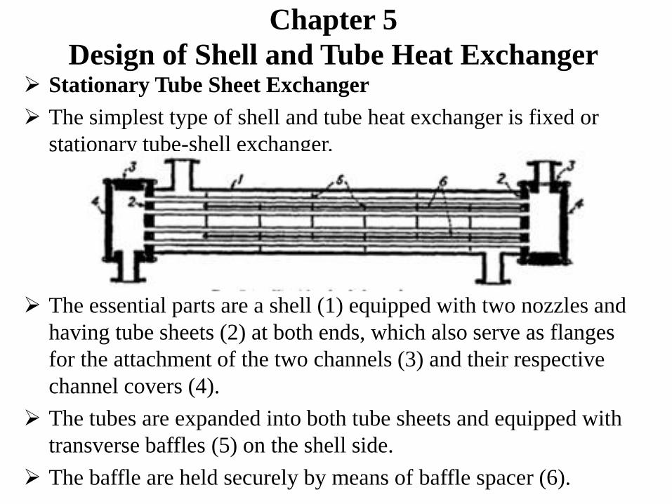
The simplest type of shell and tube heat exchanger is fixed or
stationary tube-shell exchanger.
The essential parts are a shell (1) equipped with two nozzles and
having tube sheets (2) at both ends, which also serve as flanges
for the attachment of the two channels (3) and their respective
channel covers (4).
The tubes are expanded into both tube sheets and equipped with
transverse baffles (5) on the shell side.
The baffle are held securely by means of baffle spacer (6).
Chapter 5
Design of Shell and Tube Heat Exchanger
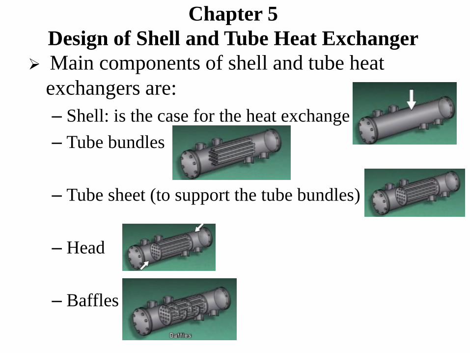
Main components of shell and tube heat
exchangers are:
– Shell: is the case for the heat exchange
– Tube bundles
– Tube sheet (to support the tube bundles)
– Head
– Baffles

Chapter 5
Design of Shell and Tube Heat Exchanger The area between inside the shell and outside the tube is called
shell side of heat exchanger. It has its inlet and outlet.
Each end of tube opens to the head, so one head into the tube
and the other out of the tube.
The area inside the tube and head called tube side of heat
exchanger.
The tube side supported inside by partition called baffle. It also
direct flow to the shell side of the HX which increases the
efficiency of the unit.
Chapter 5
Design of Shell and Tube Heat Exchanger
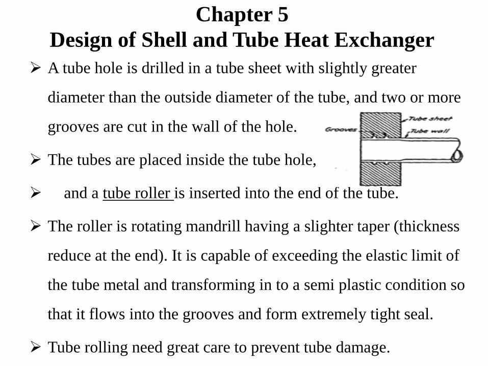
A tube hole is drilled in a tube sheet with slightly greater
diameter than the outside diameter of the tube, and two or more
grooves are cut in the wall of the hole.
The tubes are placed inside the tube hole,
and a tube roller is inserted into the end of the tube.
The roller is rotating mandrill having a slighter taper (thickness
reduce at the end). It is capable of exceeding the elastic limit of
the tube metal and transforming in to a semi plastic condition so
that it flows into the grooves and form extremely tight seal.
Tube rolling need great care to prevent tube damage.
Chapter 5
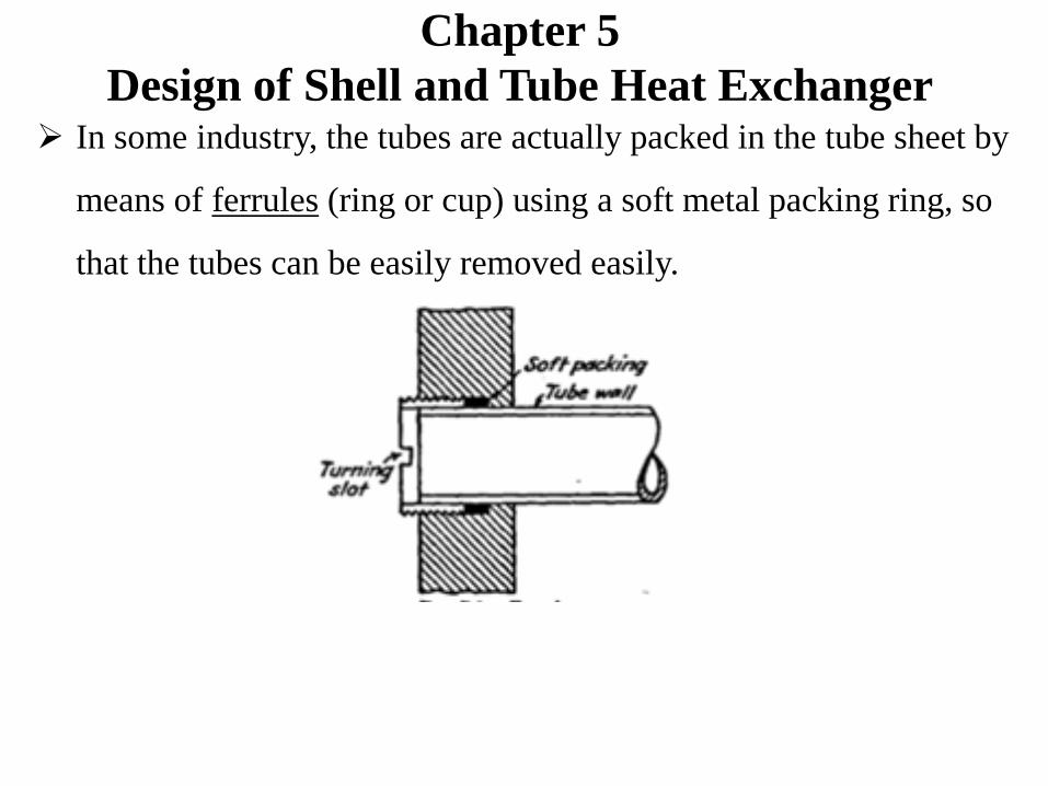
Design of Shell and Tube Heat Exchanger In some industry, the tubes are actually packed in the tube sheet by
means of ferrules (ring or cup) using a soft metal packing ring, so
that the tubes can be easily removed easily.
Chapter 5
Design of Shell and Tube Heat Exchanger Heat exchanger tubes (condenser tubes):
– They are different from steel pipes or other types of pipes which are
extruded to iron pipe size.
– The outside diameter is the actual outside diameter in inches with a
very strict tolerance.
– Can be made of steel, copper, aluminum, aluminum bronze, 70-30
copper-nickel, and stainless steel.
– They are obtained in a number of different wall thickness defined by
the Birmingham wire gage (BWG) or gage of the tubes.
– The sizes of tubes are listed in Table 10 of Appendix of which the ¾
outside diameter and 1in. OD are the most common in heat exchanger
design.
Chapter 5
Design of Shell and Tube Heat Exchanger
Tube pitches:
– Tube holes can not be dilled very close together, since too small a
width of metal between adjacent tube structurally weakens the
tubes walls.
– The shortest distance between two adjacent tube holes called
clearance (ligament).
– Tube pitch (PT) is the shortest center to center distance
between two adjacent tubes.
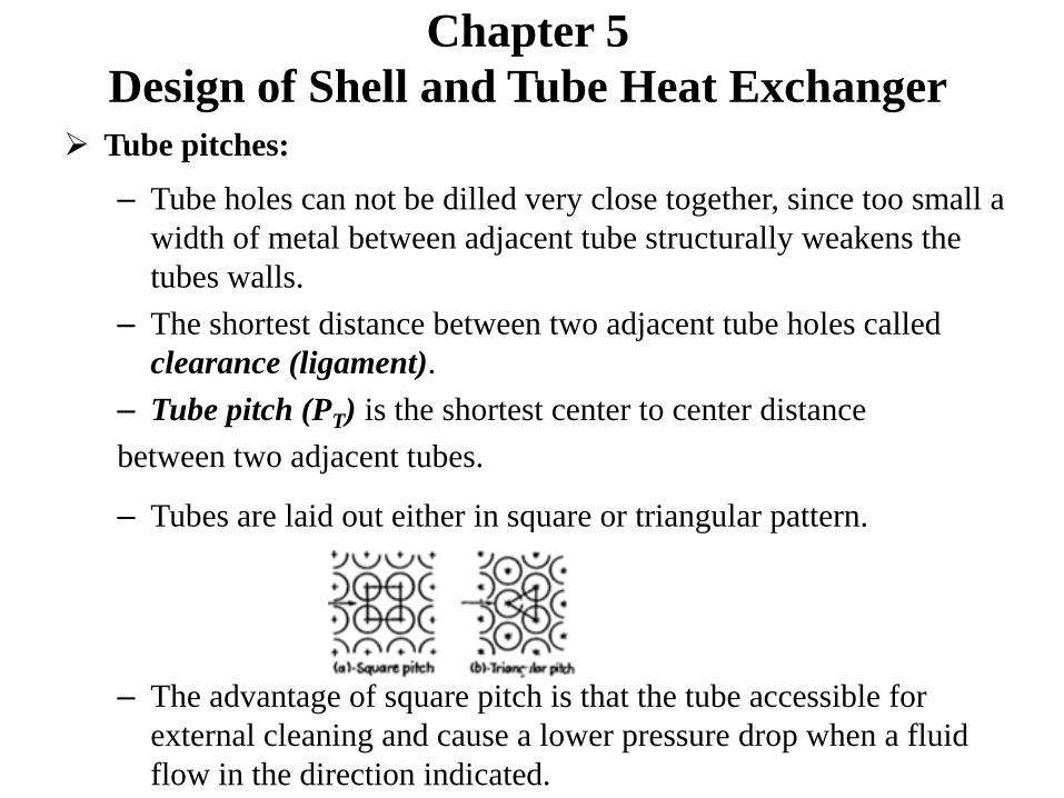
– Tubes are laid out either in square or triangular pattern.
– The advantage of square pitch is that the tube accessible for
external cleaning and cause a lower pressure drop when a fluid
flow in the direction indicated.

Chapter 5
Design of Shell and Tube Heat Exchanger
Square pitch can be rotated 450 or if the tubes are spread wide
enough, triangular pitch can include mechanically cleanable
modification.
The common pitches for square layouts are:
• ¾ in. OD on 1 in. square pitch
• 1 in. on 1 ¼ in. square pitch
The common pitches for triangular layouts:
• ¾ in. OD on 15
16in. triangular pitch
• ¾ in. OD on 1 in. triangular pitch
• 1 in. on 1 ¼ in. triangular pitch

Chapter 5
Design of Shell and Tube Heat ExchangerShell:
– They are fabricated from steel pipe with nominal IPS diameter
up to 12in. as given in the Table 11.
– Above 12in. and including 24 in. the actual outside diameter
and the nominal pipe diameter are the same.
– The standard wall thickness for shells with inside diameters
from 12 to 24 in. inclusive is 3/8 in. which is satisfactory for
shell-side operating pressure up to 300 psi.
– Pressure drop at a given thickness is to be used.
– Greater wall thickness may be obtained for grater pressure.
– Shells above 24 in in diameter are fabricated by rolling steel
plate.
Chapter 5
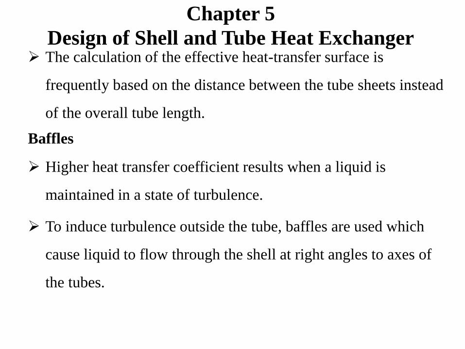
Design of Shell and Tube Heat Exchanger The calculation of the effective heat-transfer surface is
frequently based on the distance between the tube sheets instead
of the overall tube length.
Baffles
Higher heat transfer coefficient results when a liquid is
maintained in a state of turbulence.
To induce turbulence outside the tube, baffles are used which
cause liquid to flow through the shell at right angles to axes of
the tubes.
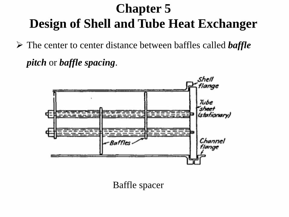
Baffle spacer
The center to center distance between baffles called baffle
pitch or baffle spacing.
Chapter 5
Design of Shell and Tube Heat Exchanger

Chapter 5
Design of Shell and Tube Heat Exchanger
Since the baffle may be spaced close together or far apart, the
mass velocity is not entirely dependent upon the diameter of the
shell. That means, it depends also on the baffle distance.
The baffle spacing is usually not greater than a distance equal to
the inside diameter of the shell or closer than one-fifth the inside
diameter of the shell.
Common types of baffles are:
Segmental baffle Disc and doughnut baffle Orifice baffle
Chapter 5
Design of Shell and Tube Heat Exchanger
Segmental baffles are dilled plates with heights which are
generally 75 percent of the inside diameter of the shell. These
are known as 25 percent cut baffle.
Even though there are different percent cut baffle, we use 25
percent cut baffle in the next lectures.
The baffle pitch, not the 25 percent cut of the baffles determines
the effective velocity of the shell fluid .
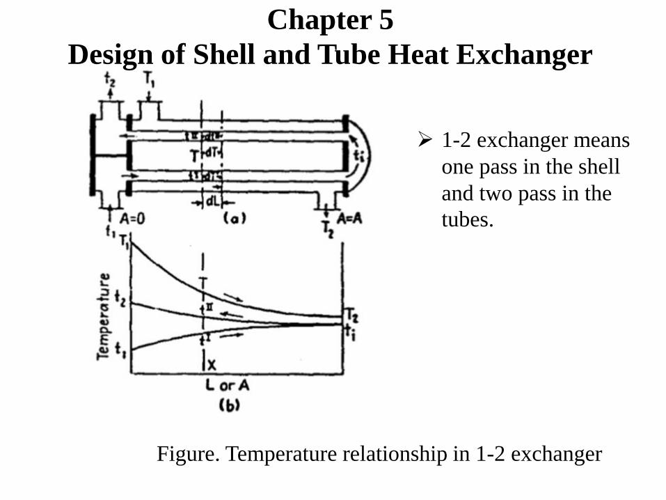
Figure. Temperature relationship in 1-2 exchanger
Chapter 5
Design of Shell and Tube Heat Exchanger
1-2 exchanger means
one pass in the shell
and two pass in the
tubes.

The assumptions in 1-2 exchanger:
1. The shell fluid temperature is an average isothermal
temperature at any cross section.
2. There is an equal amount of heating surface in each pass.
3. The overall coefficient of heat transfer is constant.
4. The rate of flow of each fluid is constant.
5. The specific heat of each fluid is constant.
6. There are no phase changes of evaporation or condensation
in a part of the exchanger.
7. Heat losses are negligible.
Chapter 5
Design of Shell and Tube Heat Exchanger
Chapter 5
Design of Shell and Tube Heat Exchanger
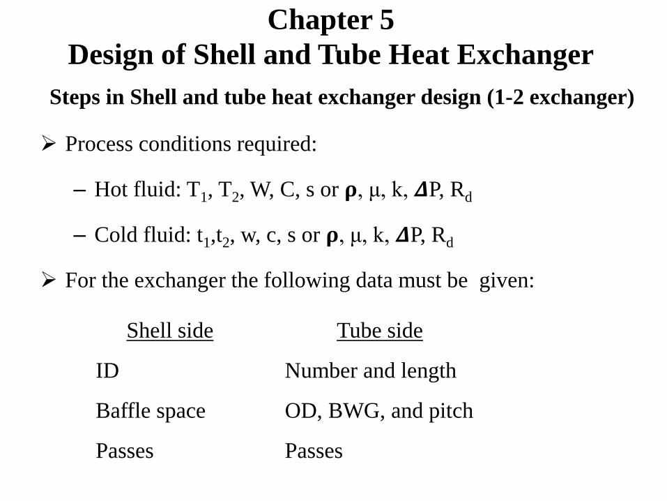
Steps in Shell and tube heat exchanger design (1-2 exchanger)
Process conditions required:
– Hot fluid: T1, T2, W, C, s or 𝛒, μ, k, 𝜟P, Rd
– Cold fluid: t1,t2, w, c, s or 𝛒, μ, k, 𝜟P, Rd
For the exchanger the following data must be given:
Tube side
Number and length
OD, BWG, and pitch
Passes
Shell side
ID
Baffle space
Passes

Chapter 5
Design of Shell and Tube Heat Exchanger1. Heat balance
Q=WC(T1-T2) = wc(t2-t1)
2. True temperature difference
For a heat exchanger with countercurrent flow, the mean
temperature difference is known as the log mean temperature
difference, ΔTLM or LMTD.
𝐿𝑀𝑇𝐷 =𝜟𝑡2−𝜟𝑡1
2.3 log (𝜟𝑡2/𝜟𝑡1)
The log mean temperature difference is the maximum mean
temperature difference that can be achieved in any geometry of
heat exchanger for any given set of inlet and outlet temperatures.
Chapter 5
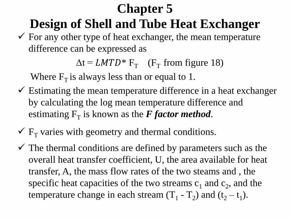
Design of Shell and Tube Heat Exchanger For any other type of heat exchanger, the mean temperature
difference can be expressed as
Δt = 𝐿𝑀𝑇𝐷* FT (FT from figure 18)
Where FT is always less than or equal to 1.
Estimating the mean temperature difference in a heat exchanger
by calculating the log mean temperature difference and
estimating FT is known as the F factor method.
FT varies with geometry and thermal conditions.
The thermal conditions are defined by parameters such as the
overall heat transfer coefficient, U, the area available for heat
transfer, A, the mass flow rates of the two steams and , the
specific heat capacities of the two streams c1 and c2, and the
temperature change in each stream (T1 - T2) and (t2 – t1).
Chapter 5
Design of Shell and Tube Heat Exchanger
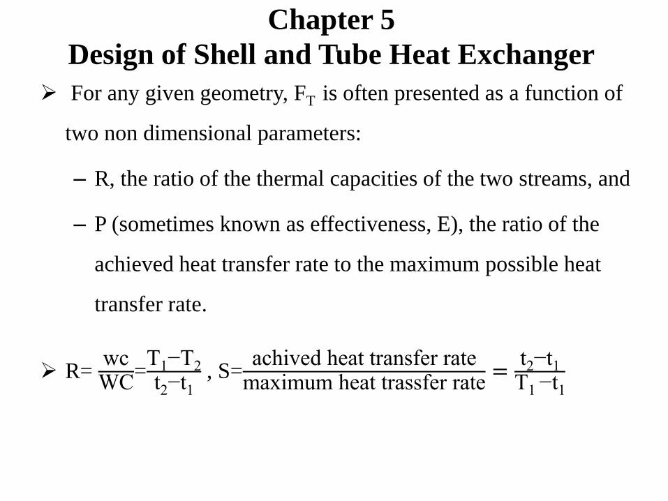
For any given geometry, FT is often presented as a function of
two non dimensional parameters:
– R, the ratio of the thermal capacities of the two streams, and
– P (sometimes known as effectiveness, E), the ratio of the
achieved heat transfer rate to the maximum possible heat
transfer rate.
R= wcWC
=T1−T2
t2−t1, S=
achived heat transfer ratemaximum heat trassfer rate
=t2−t1
T1 −t1

Chapter 5
Design of Shell and Tube Heat Exchanger
Figure. Typical relationship between F and P for various values of S (Based on
Single pass shell with any even number of tube passes).
S
Chapter 5
Design of Shell and Tube Heat Exchanger
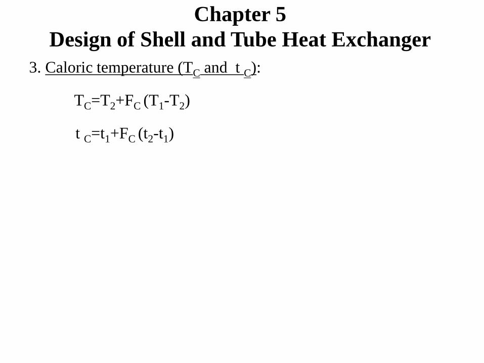
3. Caloric temperature (TC and t C):
TC=T2+FC (T1-T2)
t C=t1+FC (t2-t1)

At the end of this class:
You will have more know how about shell and tube exchanger
design
You will have the concept of true temperature difference and
caloric temperature calculation
You will be able to do the first 3 steps in shell and tube
exchanger design

End of lecture -9