Embed Size (px)
Citation preview

Thermal Effects on Alignment Stability of Electro Optical Systems
by
Dustin Hamill
A MASTER OF ENGINEERING REPORT
Submitted to the College of Engineering at
Texas Tech University in
Partial Fulfillment of
The Requirements for the
Degree of
MASTER OF ENGINEERING
Approved
______________________________________ Dr. A. Ertas
______________________________________ Dr. E. Kiesling
______________________________________ Dr. T. Maxwell
______________________________________ Dr. M. Tanik
October 15, 2005
ACKNOWLEDGEMENTS
I would like to take this opportunity to recognize and to thank those people that have been
instrumental in my work on this report. It would not have been possible without their support. First of
all, I thank the entire Texas Tech staff and the guest speakers. My instructors have shared their time, their
knowledge, and their inspirations. They have exposed me to new ideas, information, and tools for solving
real world problems. I would especially like to thank our advisor, Dr Atila Ertas, who has helped make
the past year and a half fun while keeping us on course for completion.
I would also like to thank my classmates. I appreciated networking with a talented group of
individuals each with a different background. During the courses we have taken together, I have learned
a great deal through the team projects. I would especially like to thank Tandy Penn and Laura Aguilar for
their help in study groups. Their knowledge and experience was quite beneficial.
Next, I would like to thank several colleagues at work. I thank Randy Zywicki for sparking my
interest in systems engineering and recommending me to this program. I would like to thank Lyale Marr,
Robert Davenport, Gary Schwartz, David Norman, and Kent Henrichs for imparting their knowledge,
experiences, and research materials related to this report.
Finally, I would like to thank my wife, Diana and children, Jacob and Gabrielle. I appreciate them
putting up with my time away as I was not available for every activity and household duty. I am blessed
with a patient family and I love them greatly.
ii

TABLE OF CONTENTS
ACKNOWLEDGEMENTS ........................................................................................................ II
TABLE OF CONTENTS ...........................................................................................................III
DISCLAIMER.............................................................................................................................. V
ABSTRACT.................................................................................................................................VI
LIST OF FIGURES .................................................................................................................. VII
LIST OF TABLES ....................................................................................................................... X
CHAPTER I INTRODUCTION......................................................................................................................... 1
CHAPTER II BACKGROUND OF ELECTRO OPTICAL SENSOR SYSTEMS ........................................ 3 2.1 Types of Systems 3 2.2 Internal System Components 8 CHAPTER III DESIGN PARAMETERS FOR THERMAL ALIGNMENT STABILITY .......................... 13 3.1 Overview 13 3.2 Optical Layout and Budget Analysis 14 3.3 Structural Design and Fabrication 18
3.3.1 Dimensional Stability................................................................................................. 18 3.3.2 Main structure ............................................................................................................ 21 3.3.3 Optical mounting........................................................................................................ 26 3.3.4 Mechanisms................................................................................................................ 33 3.3.5 Inertial Stabilization ................................................................................................... 35
3.4 Thermal Design 37 3.4.1 Hot Temperature Extremes ........................................................................................ 38 3.4.2 Cold Temperature Extremes....................................................................................... 40 3.4.3 Thermal Effects on Optical Elements ........................................................................ 42
CHAPTER IV ALIGNMENT STABILITY TEST METHODS AND EQUIPMENT................................... 46 4.1 Test Equipment 46 4.2 Variability 51 4.3 Example System Test Methods 52
4.3.1 Sensor-to-sensor alignment stability .......................................................................... 53 4.3.2 Laser-to-sensor alignment stability ............................................................................ 53
4.4 Example Component Test Methods 54 CHAPTER V LASER ALIGNMENT AND RETENTION METHODS....................................................... 59 5.1 Temperature calibration 59 5.2 Boresighting on the Vehicle 59
5.2.1 Boresight Modules ..................................................................................................... 59 5.2.2 Internal Methods ........................................................................................................ 62
iii

5.3 Active Correction 63 CHAPTER V I CASE STUDY: USING PRINCIPLES OF AXIOMATIC DESIGN TO SOLVE AN ALIGNMENT STABILITY PROBLEM ................................................................................. 65 6.1 Axiomatic Design Background 65 6.2 Analysis of the Product Using Axiomatic Design 66 6.3 Problem Description 67 6.4 Function Tree (Design Object Analysis) 67
6.4.1 Description of the Major Components ....................................................................... 69 6.5 Noise Factor Analysis 70 6.6 Gathering and Analyzing Initial Data 71 6.7 Statistical Experimental Design 72
6.7.1 Initial Decisions.......................................................................................................... 72 6.7.2 Experimental Setup .................................................................................................... 74 6.7.3 Analysis of Variance (ANOVA) ................................................................................ 75
6.8 Optimization, Redesign, and Decoupling 77 6.9 Creation of an Implementation Plan 78 6.10 Verification: Is the Problem Solved? 78 6.11 Case Study Conclusion 78 CHAPTER VII SUMMARY AND CONCLUSIONS ......................................................................................... 80
REFERENCES............................................................................................................................ 82
iv

DISCLAIMER
The opinions expressed in this report are strictly those of the author and are not necessarily those
of Raytheon, Texas Tech University, nor any U.S. Government agency.
v
ABSTRACT
Electro optical systems are designed with different sensors and lasers for a variety of military and
scientific uses over a broad range of environmental temperatures. Many of these systems have strict
boresight retention requirements among their sensors and lasers. Thermal effects are the primary cause
for alignment drift during operation. This paper discusses temperature effects on optical components and
their surrounding structure. Thermal expansion and contraction of materials can result in several
undesirable effects such as a loss of image and beam quality, but the primary focus of this paper is
boresight drift. Several opto-mechanical guidelines combined with thermal management are described
for minimizing alignment drift. Test equipment and methods to validate alignment stability of systems
and individual components over temperature are also presented. Additional laser alignment retention
methods are discussed, including calibration, boresighting schemes, and active correction. Finally, a case
study presents the use of axiomatic design analysis and design of experiments to find the main
contributors of an alignment drift problem.
vi
LIST OF FIGURES
Figure 1: Electromagnetic Spectrum [Boreman, 1998] 3
Figure 2: Telescope optical ray trace [O’Brian, 2003] 4
Figure 3: Space EO Sensor System [Mainzer, 1998] 5
Figure 4: Infrared Image Sample [Jane’s, 2005] 6
Figure 5: Military EO Targeting System [Jane’s, 2005] 7
Figure 6: Nose mounted EO Sensor System [Jane’s, 2005] 7
Figure 7: Example of system components: CALIPSO LIDAR [Seckar, 2005] 8
Figure 8: Laser Resonator Cavity Architecture 10
Figure 9: Schematic of a LIDAR, with common T/R aperture [Feng, 1995)] 11
Figure 10: Optical Layout, from IRMOS, cryogenic IR imager [Hylan, 2003] 14
Figure 11: Penta prism (A), its mirror equivalent (B), a periscope prism (C) and its mirror equivalent (D) [Wilson, 1990] 15
Figure 12: Retroreflectors [PLX Inc., 2005] 16
Figure 13: Optical Error Budget from IRMOS [Hylan, 2003] 17
Figure 14: Coefficients of Thermal Expansion for Common EO Materials [Zona, 2001] 18
Figure 15: Optimum Aluminum Mirror Stress Relief Process [Adapted from Ohl, 2002] 21
Figure 16: Thermal gradient induced tilt of an optical structure 22
Figure 17: IRMOS aluminum optical bench [Hylan,2003] and example cast bench [Yoder,1990] 23
Figure 18: Common material (SiC) optical bench and primary mirrors with isolator struts [Veggel, 2005] 26
Figure 19: Proper constraints for a stationary thermal center [Giesen, 2003] 27
Figure 20: Two kinematic mounting types and their thermal centers [Giesen, 2003] 28
Figure 21: SiC mirror mounted with vee pairs and clamped with a spider [Veggel, 2005] 28
Figure 22: Low stress, stable aluminum mirror mounting technique used in IRMOS [Hylan,2003] 29
vii

Figure 23: Temperature stable, low stress flexure mount for mirrors [Giesen, 2003] 30
Figure 24: Thermally stable mount for a prism beam splitter [Veggel, 2005] 31
Figure 25: Various lens mounting techniques [adapted from Yoder, 1999] 32
Figure 26: Lens Clamping Flexure Ring Design [Kvamme, 2005] 33
Figure 27: Cryogenic Mount- with flexure ring and axial flexures [Kvamme, 2005] 33
Figure 28: Cryogenic filter and grating wheels [Hofferbert, 2003] 34
Figure 29: Stable flexure design adjustment mount. [Lee, 2003] 35
Figure 30: Fast Steering Mirror [Mitchell, 2001] 36
Figure 31: System thermal behavior [Giesen, 2003] 37
Figure 32: Beam deviation due to a transverse temperature gradient in a window 43
Figure 33: Bimetallic Compensator Tube [Vukobratovich , 1993] 44
Figure 34: Collimator for testing optical alignments of an EO system. [Dickey,1980] 46
Figure 35: Collimator primary mirror aperture coverage [Dickey,1980] 47
Figure 36: Autocollimator Schematic [Leviton, 2003] 48
Figure 37: Visible Autocollimator [Leviton, 2003] 49
Figure 38: Quadrature detector [Hane , 2003] 50
Figure 39: Temperature Chamber Setup [Zona, 2001] 51
Figure 40: Alignment Drift and Shift [Wilson, 2005] 52
Figure 41: Sample autocollimator image with two mirror returns 54
Figure 42: Example of a component test fixture [Zona, 2001] 55
Figure 43: Alignment stability test fixture for single autocollimator measurement 56
Figure 44: Alignment stability testing of a beam expander using single autocollimator 56
Figure 45: Dual Autocollimator setup for two apertures spaced apart 57
Figure 46: Laser alignment stability test 58
Figure 47: Collimator boresight module for a single input/output axis [Godfrey, 1980] 60
viii

Figure 48: Collimator boresight module for two optical axes [Godfrey, 1980] 61
Figure 49: Mini-collimator boresight module using a dichroic beamsplitter [Godfrey, 1980] 61
Figure 50: Internal Boresighting Techniques using a Corner Cube [Gibson, 2000] 62
Figure 51: Boresighting method using a lateral transfer prism [Godfrey, 1980] 63
Figure 52: Active Beam Alignment Compensation [Mitchell, 2001] 64
Figure 53 - Axiomatic Design Process [Englehardt, 2000] 66
Figure 54: Example of a targeting pod [Jane’s, 2005] 67
Figure 55: Partial Functional Analysis Tree 68
Figure 56: Optical Schematic 69
Figure 57: Noise Factors 70
Figure 58: Cause and Effect Possibilities 71
Figure 59: Initial Estimates of Probable Contributors to the Problem 74
ix

LIST OF TABLES
Table 1: Properties of Common Mirror and Structural Materials at 300K [Paquin, 1999] 25
Table 2: L8 Array and descriptions 75
Table 3: ANOVA Results 77
x

CHAPTER I INTRODUCTION
Most electro-optical sensor systems are designed to meet specific customer needs including
scientific measurements, mapping, imaging, ranging and military targeting. These ground, airborne, or
space systems commonly contain combinations of sub-systems like telescopes, color television cameras,
infrared cameras, spectrometers, laser radars, laser illuminators, laser rangefinders, and laser designators.
The customer needs are mapped into a functional requirements document, and the design parameters are
formed from the functional requirements. The alignment retention of optical subsystems over a broad
operating temperature range can be a challenging functional requirement because of its dependency on a
multitude of design parameters.
Optical alignment or “boresight” retention can be defined differently depending upon the
configuration of the optical system. Most often it is how well an optical axis remains aligned with respect
to a mechanical reference axis. Sometimes alignment retention is broken up into several requirements.
For example, alignment retention could be how well one sensor’s optical axis maintains alignment with
another sensor’s or source’s optical axis. Simultaneously, each sensor may also be required to stay
aligned to an external mechanical datum. Most high-resolution space telescopes also have functional
requirements of optical alignment stability to maintain image quality and minimum wave front error.
Maintaining optical alignment throughout a changing temperature environment is difficult to
accurately model with typical non-isothermal designs. Some complex electro-optical systems contain so
many variables, that thermo-elastic models are fortunate to achieve order of magnitude predictions of
alignment stability. The recommended approach for successful alignment stability involves following
proven design guidelines, testing of system components, and then testing a complete system prototype.
Component fabrication and assembly techniques can also introduce variability of alignment stability.
Depending upon the design constraints, many different configurations of opto-mechanical designs
have been tested and deployed over the years. These designs serve as lessons learned in making systems
1

perform over temperature. The development of space telescopes and scientific imaging payloads has
brought out many guidelines for building stable optical bench designs.
In order to verify alignment retention over temperature, special test setups are necessary. It
requires careful attention to ensure that the errors in the test setup can be measured and are controlled.
The alignment of an optical system as a whole can be characterized over temperature to verify stability.
Individual sub-assemblies or optical elements can also be characterized outside the system using special
fixtures and reference mirrors.
When the required laser alignment stability is not achieved passively with structural and thermal
design, other methods can be employed to maintain optical alignment. These methods include
calibration, feedback control, and alignment modules. Each method has strengths and weaknesses, with
the best method most often selected based on customer needs and design constraints.
Most of today’s sensor systems have stringent angular alignment retention requirements that in
the sub-100 micro-radian range, over military standard temperature environments of +71 to –54C (Zona,
2001). Other EO systems must stay aligned from laboratory assembly temperatures to cryogenic
operating temperatures of space. Robust opto-mechanical structures combined with prudent thermal
management is paramount to stable system boresight and customer satisfaction.
2

CHAPTER II BACKGROUND OF ELECTRO OPTICAL SENSOR SYSTEMS
2.1 Types of Systems
During the period of 1900 to 1980, the development of optics and electronics merged into a
specific field known as electro-optics. “EO” sensors were born when a light-sensitive electronic detector
was first placed at the focal plane of a converging optical lens. The detector produced a signal,
proportional to the amount of radiation collected by the lens, which could be relayed to another location
to be converted back into visible radiation for display to an operator. Today, the field of electro-optics
covers a broader portion of the electro-magnetic spectrum than just visible light. The “optical” bands of
interest, listed in increasing wavelength, include ultraviolet, visible, near infrared, mid-wave, and long-
wave infrared as shown in Figure 1.
Figure 1: Electromagnetic Spectrum [Boreman, 1998]
These wavelengths range from 0.05 to 14 micrometers, and like visible light, can form images
through the use of appropriate lenses and mirrors. Generally speaking, EO systems are concerned with
3

the collection or emission of radiation in this “optical” spectrum. Some common EO sensor systems
contain telescopes, seekers, infrared detectors, visible cameras, image intensifier tubes, spectrometers,
and laser systems. For each of these components to function effectively, the optical elements must be
aligned accurately, as shown in a sample telescope ray trace in Figure 2.
Figure 2: Telescope optical ray trace [O’Brian, 2003]
EO sensor systems have a broad range of use in both military and scientific applications.
Examples include target acquisition, fire control, reconnaissance, navigation, missile seekers,
astronomical telescopes, and scientific satellite payloads. Satellite systems, for example, must survive
launch vibrations and the extreme temperatures of space. EO sensors have been deployed in space for
collection of weather data, mapping the earth, atmosphere composition studies, and of course studying
other celestial bodies. In the absence of solar radiation, the temperature in space approaches absolute zero
resulting in a 200 degree Celsius reduction in the optics’ temperatures, as compared to laboratory
alignment temperatures. In contrast, solar radiation can present another challenge to alignment stability
by generating large thermal gradients in an otherwise cold satellite structure. An example satellite EO
4

instrument is shown in Figure 3. The many lessons learned in the development of space sensors can
prove valuable to the opto-mechanical design of ground and airborne EO sensors for improved alignment
stability. These include choices of optical materials and structural design.
Figure 3: Space EO Sensor System [Mainzer, 1998]
Military EO sensor systems typically contain infrared (IR) or visible television (TV) cameras
along with other devices such as lasers and laser receivers. These systems are mounted to both ground
and airborne vehicles such as tanks, light armored vehicles, airplanes, and helicopters. Due a reduction in
the atmospheric absorption of infrared energy in the 3-5 micrometer and 8-12 micrometer wavelength
range, most infrared sensors operate in these middle and long wave IR bands. Infrared detectors coupled
with collection and focusing optics are known as Forward Looking Infrared devices or FLIR. IR sensors
detect an infrared signature or small differences in temperature and surface emissive features, making
them advantageous for viewing scenes at night as well as visibly camouflaged targets during the day. IR
video is typically displayed in 256-color gray scale format as shown in Figure 4. This image was taken
5

using a sensor onboard the Joint Strike Fighter prototype (Jane’s, 2005). Notice the aiming reference
used is a digital reticle. The sub-image shows zoom capabilities of the sensor.
Figure 4: Infrared Image Sample [Jane’s, 2005]
For pure reconnaissance systems, the EO sensors aboard a high altitude loitering aircraft and may
only be required to stay aligned to the aircraft’s navigation system. Targeting systems similar to the one
shown in Figure 5, typically align the EO sensor to a weapon or laser. For tank sights, the infrared reticle
or “line of sight” (LOS) must be aligned to the gun’s datum axis, so that a proper gun aiming ballistic
solution can be computed. Many ground and airborne EO systems employ a targeting laser, which must
be aligned to the FLIR or visible camera LOS. The alignment of the laser is critical for accurate range
calculations and for designation of targets for laser guided bombs and missiles. The guided “smart”
munitions incorporate their own EO sensor, called a seeker to guide the ordinance to the target, which is
being illuminated with a laser beam.
6
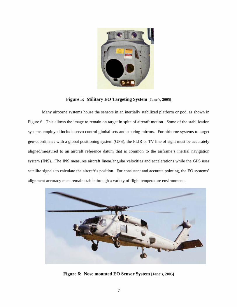
Figure 5: Military EO Targeting System [Jane’s, 2005]
Many airborne systems house the sensors in an inertially stabilized platform or pod, as shown in
Figure 6. This allows the image to remain on target in spite of aircraft motion. Some of the stabilization
systems employed include servo control gimbal sets and steering mirrors. For airborne systems to target
geo-coordinates with a global positioning system (GPS), the FLIR or TV line of sight must be accurately
aligned/measured to an aircraft reference datum that is common to the airframe’s inertial navigation
system (INS). The INS measures aircraft linear/angular velocities and accelerations while the GPS uses
satellite signals to calculate the aircraft’s position. For consistent and accurate pointing, the EO systems’
alignment accuracy must remain stable through a variety of flight temperature environments.
Figure 6: Nose mounted EO Sensor System [Jane’s, 2005]
7
2.2 Internal System Components
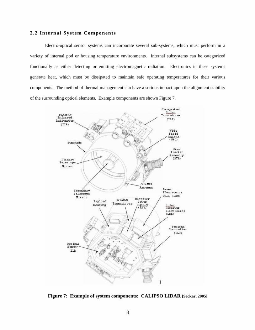
Electro-optical sensor systems can incorporate several sub-systems, which must perform in a
variety of internal pod or housing temperature environments. Internal subsystems can be categorized
functionally as either detecting or emitting electromagnetic radiation. Electronics in these systems
generate heat, which must be dissipated to maintain safe operating temperatures for their various
components. The method of thermal management can have a serious impact upon the alignment stability
of the surrounding optical elements. Example components are shown Figure 7.
Figure 7: Example of system components: CALIPSO LIDAR [Seckar, 2005]
8
In the early days of television cameras, a vidicon tube was placed at the image plane of a lens
system to convert visible light into an electronic signal. Charge coupled devices (CCD) are now the heart
of most visible wavelength cameras. CCD’s convert photons to electrons via tiny detectors on a
semiconductor chip that may be doped with exotic materials to improve performance. Most infrared
detector elements are also doped semiconductors. Due to manufacturing issues regarding the fabrication
of two-dimensional arrays, infrared detectors consisted of only a single line of detector elements placed
behind mechanical scanning systems. Thanks to advances in semiconductor producibility, today’s
infrared detectors are starring focal plane arrays composed of thousands of detector elements. Most
detectors require cooling to cryogenic temperatures to achieve a required sensitivity. Cryo-coolers, used
to reduce a detector’s temperature, can be a heat source to the surrounding components in an EO system,
and the heat must be removed from the system.
The emission of photons from EO systems is most often accomplished with a laser and various
conditioning optics. The term “LASER” is an acronym for Light Amplification by Stimulated Emission
of Radiation. Light is amplified by a gain medium, which is a material that emits photons when excited
by input photons. Laser light exiting the gain medium is coherent (light waves vibrating in phase).
Lasers typically emit a fine band or “line” of light, centered at a wavelength specific to the gain medium,
so lasers are typically classified by the chemical composition of the medium. For example, a HeNe laser
typically operates at 632 nm and contains helium-neon gas. Laser lines have been developed across the
whole “photonic” spectrum from ultraviolet to long-wave infrared. The gain medium must be pumped
with a light source in order to stimulate the emission of photons. This process is highly inefficient when
comparing input energy to exiting laser energy. This results in a large quantity of heat that must be
removed from the gain medium. The most common gain media are gas cavities and solid crystals that are
doped to enhance the properties. Besides the gain medium, the laser resonator cavity also contains
reflectors on each end. One reflector is a partial reflector for allowing output energy as shown in Figure
8. Lasers typically have several conditioning optics such as focusing optics for improving the collimation
or parallel qualities of the beam. Beam expanders are also used to improve the beam’s divergence, which
9

is the angular subtense of the exiting beam. The alignment stability of laser optics is key to accurate
pointing of the laser. Care must be taken to dissipate heat away from the gain medium without inducing
optical misalignments. Laser assemblies require robust opto-mechanical design for stable alignment
through various operating temperatures.
Pump
Gain Medium
ReflectorPartial
Reflector
Output
Figure 8: Laser Resonator Cavity Architecture
In EO sensor systems, lasers are used for rangefinders, designators, illuminators, and radars. A
rangefinder measures the propagation time of a short laser pulse to and from a target, and it calculates the
distance to the target. A designator paints a target with coded pulses of infrared light in order to guide
missiles and bombs to the target. Illuminator lasers are used to light up a target area with infrared energy
for either an onboard or remote camera to view. A laser radar or LIDAR examines the range of the return
for each pixel in a field of view (FOV) to produce an image of the scene. For each of these applications,
the output laser must be aligned and maintained to one or more sensors or datum. Accurate pointing of
the laser requires an accurate beam steering system, which must also maintain alignment over
temperature.
There are a variety of optics and optical materials used in EO systems. Each material has
different optical and thermal properties. Optical elements include mirrors, beam splitters, lenses,
windows, and prisms. These optical elements must be mounted without stress, which will induce wave
front error thereby degrading image/beam quality. Unfortunately, a low stress mount does not imply a
temperature stable mount. Mirrors can be flat for folding the path into a compact space, or for steering a
beam. Mirrors with curvature have “power” and are used in telescopes or afocals for the collection of
10

energy and providing a desired field of view. Imaging optics can utilize curved mirrors or lenses for
focusing the energy down to a small image plane. Mirror designs include different glasses and metals
that are typically coated with thin films for peak reflections at desired wavelengths. Only certain
materials transmit specific wavelengths of electromagnetic radiation. Often the wavelength requirements
drive the material selection for windows, lenses, beam splitters, and prisms. Lenses can be positioned in
focus cells and switching mechanisms to provide optimum image quality for different field of views and
image magnification. Beam splitters (BS) are useful for separating a beam into two paths each of the
same wavelength, or for separating bands of energy into two different paths based on wavelength through
different coatings on the optical surfaces.
Figure 9: Schematic of a LIDAR, with common T/R aperture [Feng, 1995)]
As shown in Figure 9, a common LIDAR transmit/receive (T/R) path requires a main beam
splitter, along with four additional beam splitters. Notice the system shares a common telescope for beam
11
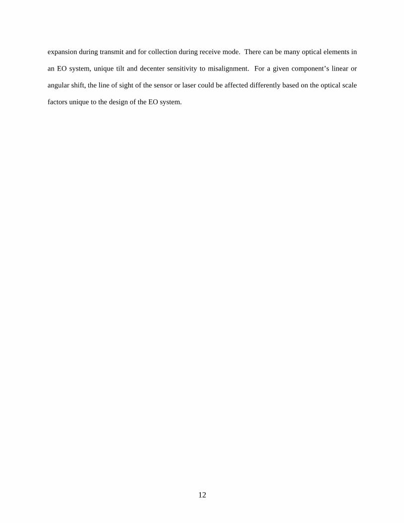
expansion during transmit and for collection during receive mode. There can be many optical elements in
an EO system, unique tilt and decenter sensitivity to misalignment. For a given component’s linear or
angular shift, the line of sight of the sensor or laser could be affected differently based on the optical scale
factors unique to the design of the EO system.
12

CHAPTER III DESIGN PARAMETERS FOR THERMAL ALIGNMENT STABILITY
3 .1 Overview
When considering alignment stability, one should consider the effects of vibration, shock, and
temperature changes, however the primary focus of discussion will be the effects of environmental and
internal operating temperature changes that are induced in electro-optical systems. Temperature changes
create deformations, which typically cause the light path to deviate from its initial alignment axis. In
general, the movement of individual optics, bending of the structure, or optical property changes, causes
light path deviations. The many options for minimizing thermal disturbances on optical systems can be
broken into four categories:
A. Use of designs in which deformations of the EO system do not affect the optical path
B. Use of combinations of materials to counteract thermal expansion
C. Use of materials with low thermal expansion
D. Matched materials: optical path is insensitive to the scaling of optics (Giesen, 2003).
These guidelines can be applied during the design and development of an EO system.
After defining customer needs and functional requirements, the proper design process for an EO
system involves generation of an optical prescription and layout. The optical designer creates an optical
simulation model and determines tolerance and error budgets for component alignment. The opto-
mechanical design is integral to the optical layout. Factors to be considered include material selection for
dimensional stability, main structure rigidity, and the mounting of optics. An important but sometimes
overlooked element of alignment stability involves system-level thermal design and thermal management,
which considers optical alignment stability. Most often assembly, alignment, and test are performed at
room temperature, however fielded systems function at both hotter and colder temperatures. Thermal
design considerations include methods to dissipate excess heat of electronics, avoid condensation on
optics, and maintain minimum operating temperatures for electronics, without affecting the optical
13
alignment. Another thermal design detail involves the change in focus of refractive optics over
temperature. Finally, any mechanisms required in a system, must be carefully designed for repeatability
and optical alignment stability over temperature.
3.2 Opt ical Layout and Budget Analys is
Most often, the target size, range of detection, field of view, sensitivity, and desired sensing
wavelength drive the sensor optical prescription. Laser source optics are generally driven by the
wavelength, the desired beam size on the target, receiver sensitivity, and any feedback sampling optics.
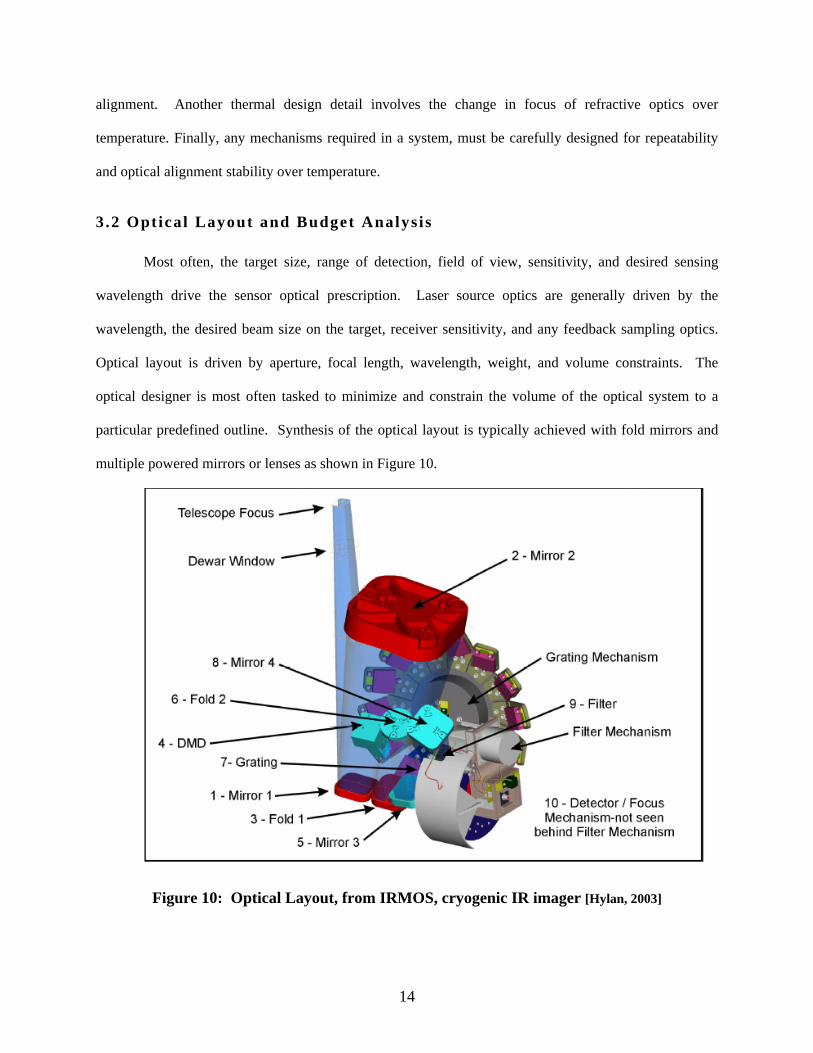
Optical layout is driven by aperture, focal length, wavelength, weight, and volume constraints. The
optical designer is most often tasked to minimize and constrain the volume of the optical system to a
particular predefined outline. Synthesis of the optical layout is typically achieved with fold mirrors and
multiple powered mirrors or lenses as shown in Figure 10.
Figure 10: Optical Layout, from IRMOS, cryogenic IR imager [Hylan, 2003]
14

Several optical layout methods have been used to improve alignment stability between sensors.
Shared aperture reflective telescope designs allow multiple sensors to use a common collection aperture.
Any drift of the telescope optics equally impacts each sensor, so the sensor-to-sensor alignment stays un-
altered. When designing for laser beam stability, most often a telescope, referred to as a beam expander,
is used to reduce the input alignment drift due to the laser itself and reduce the laser’s divergence angle.
For some applications, the sensor collection telescope can also serve as a beam expander for the output
laser, adding a common path for stability. The output laser angular drift is reduced by the telescope
magnification that is the beam expansion ratio due to the physics of the design. The penta prism can
replace a fold mirror to make a beam or light bundle turn exactly 90 degrees as shown in Figure 11. The
benefit of this prism is that the output optical axis is insensitive to angular alignment of the penta-prism.
(C) (D)
Figure 11: Penta prism (A), its mirror equivalent (B), a periscope prism (C) and its mirror equivalent (D) [Wilson, 1990]
Similarly, periscopes, lateral transfer prisms, corner cubes, and retroreflectors are also insensitive
to angular alignment changes. A periscope is used to displace the beam parallel to the input path without
affecting the output angle. A lateral transfer prism or retroreflector is a piece of a corner cube as shown
in Figure 12, and is used to displace a beam over some distance and return it parallel to the incoming
beam. A corner cube prism is made of solid glass and a retroreflector is made of bonded mirrors.
15

Figure 12: Retroreflectors [PLX Inc., 2005]
After the optical layout is complete, the optical designer performs a statistical tolerance analysis
of each optical element’s location and size in order to meet boresight needs, desired wave front error on
an interferometer and eventually to meet imaging requirements, most often specified as modulation
transfer function (MTF). The alignment tolerances refer to the assembly and test of the optical assembly
before fielded operation and the stability requirements refer to allowable operational variability in all
fielded environments. Using both the alignment retention requirements such as sensor-to-sensor or
sensor-to-laser, and the MTF requirements, an alignment stability error budget for each component should
be allocated as shown in Figure 13, which was developed for the IRMOS program, a cryogenic IR
spectrometer for an observatory telescope. The stability budget can be adjusted upon performance and
cost trade-off considerations by loosening up some areas and tightening up others. Care should be taken
to assign a budget to every component that could cause alignment drift. This should include the
structure’s contribution and if installed, the laser’s contribution. The goal would be to have all of the
component budget’s root-sum-square (RSS) stay below the system specification.
16
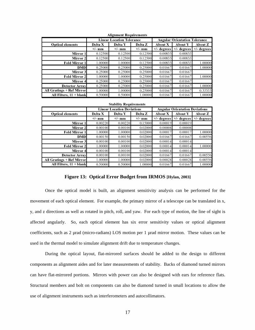
Figure 13: Optical Error Budget from IRMOS [Hylan, 2003]
Once the optical model is built, an alignment sensitivity analysis can be performed for the
movement of each optical element. For example, the primary mirror of a telescope can be translated in x,
y, and z directions as well as rotated in pitch, roll, and yaw. For each type of motion, the line of sight is
affected angularly. So, each optical element has six error sensitivity values or optical alignment
coefficients, such as 2 µrad (micro-radians) LOS motion per 1 µrad mirror motion. These values can be
used in the thermal model to simulate alignment drift due to temperature changes.
During the optical layout, flat-mirrored surfaces should be added to the design to different
components as alignment aides and for later measurements of stability. Backs of diamond turned mirrors
can have flat-mirrored portions. Mirrors with power can also be designed with ears for reference flats.
Structural members and bolt on components can also be diamond turned in small locations to allow the
use of alignment instruments such as interferometers and autocollimators.
17

3.3 Structural Des ign and Fabricat ion
When concerned with alignment, the most important mechanical parameters are those that
influence the deflection of the structure or optics of the optical system. There are several properties that
can cause deflections including self-weight, thermal distortion, vibration, dimensional stability, and
improper mounting (Vukobratovich, 1993). Thermal distortion is the main cause of alignment stability
issues in EO systems. The material property that describes the change in size of a component as its
temperature changes is called the coefficient of thermal expansion (α) or CTE. This property has been
studied for many optical and structural materials and is given in units of (in/in per deg. F) or (m/m per
deg. K) (Vukobratovich, 1993). When calculating how much a component will grow, the following
equation is used: ( α** Tlengthlength ∆=∆ ). This appears simple when only using the average CTE,
but each material’s CTE varies non-linearly over temperature. For small changes in temperature, the
change in CTE can be linearly approximated as shown in Figure 14, as “Delta CTE”. Most published
CTE’s for materials are only given near room temperature. In some materials the CTE is not homogenous
through the component and can cause internal stresses and surface deformations over temperature. The
coefficient of thermal expansion is a continuous parameter that must be addressed in many parts of the
design of EO systems.
Figure 14: Coefficients of Thermal Expansion for Common EO Materials [Zona, 2001]
3.3 .1 Dimensional Stabi l i ty
A component’s “dimensional stability” is a misnomer and is actually the degree of controlled
instability. Every material has some form of dimensional instability caused by either internal or external
influences. One goal in the design process is to select materials and manufacturing processes that will
18
ensure the overall error budget is met. The three main categories of dimensional instability are temporal,
thermal, and hysteresis related. Temporal instability is the change in dimension of a component over a
period of time in a constant environment. Some materials are worse than others and variability can
depend upon the amount of residual stress left in the component. Invar material, which is supposed to be
“invariant” to small temperature changes, is known for its poor long-term dimensional stability especially
if the recommended heat-treating process is not followed. Hysteresis in a component is the permanent
dimensional change experienced after a thermal cycle or mechanical loading cycle. The relaxation of
residual stresses is the usual suspect for causing both temporal and hysteresis dimensional instability.
Thermal instability, caused by the CTE, is the change in dimension of a component from one temperature
to another temperature. This change is usually reversible upon returning to the same temperature (Paquin,
1999).
For an optical assembly to remain aligned over temperature, each component and the structure
must maintain its allocated dimensional stability as defined by a comprehensive error budget. The first
step in achieving desired results with metals involves controlling the relaxation of residual stress.
Residual stresses in materials can result from fabrication processes including heat treatment, mechanical
working (forming, bending, surface hardening), machining, plating, and welding. New stresses can also
form during operation inside an EO system due to externally applied forces such as static mounting stress,
vibration, and temperature cycling.
Unfortunately, materials do not behave perfectly. Ideally most metals have an elastic region that
is approximated by Hooke’s law which says when a given load is applied, the material will deform, and
when the load is removed the material returns to its original shape. The amount of stress required to
cause permanent strain (plastic deformation) on the order of 10E-6 meter deformation/meter is called
microyield stress, or MYS. The MYS is lower for annealed parts and is higher for parts of the same
material with residual stress. This is a competing issue, of strength to stability. Material properties such
as grain size, dislocations, and lattice strains can be altered to improve MYS with special alloys. The rule
of thumb for stability is to keep stress levels at half the MYS limit (Vukobratovich, 1993). The MYS is
19

material and process dependent; the best selection will improve stability when going over temperature, as
a component’s mounting, vibration, and thermal stress level should be kept below the MYS to maintain
precision alignment.
Internal sources of residual stress are difficult to quantify, but processes have been developed to
minimize them (Paquin, 1999). Machining can cause surface residual stresses resulting in CTE
differences through the part. The state of the material before machining such as being annealed or heat-
treated, also affects the state of residual stresses in a component. Inhomogeneous CTE inside two-phase
materials like alloys can cause residual stresses. Frequently, a part is heated and quenched in water to
obtain a desired strength by adding residual stress through dislocations in the crystal lattice structure,
resulting in a loss of dimensional stability. Several stress-relieving operations exist and the appropriate
one for the desired error tolerance is dependent upon the material. Four main stress relief options are
available:
1. Thermal treatments involving isothermal exposure of thermal cycling,
2. Mechanical treatments such as vibration or mechanical working,
3. Removal of stress layer by chemical etching, polishing, fine grinding, and
4. Time (Paquin, 1999).
Thermal treatments and surface removal typically result in a dimensional change with added
stability at the new dimension. Surprisingly, some stress relief can be achieved by just allowing a
component to sit on a shelf for a period of time. One proven technique for dimensional stability is to use
multiple step fabrication process. First a rough machine process is performed, followed by a high
temperature cycle, a fine machine process, and low temperature aging/temperature cycling
(Vukobratovich 1993).
A specific example of maintaining tight dimensional stability and alignment was demonstrated in
the development and testing of a cryogenic IR spectrometer called IRMOS for NASA. Some of the tight
stability requirements and the optical layout were previously featured in Figure 10 and Figure 13. This
design was aligned at room temperature (300K) and maintained alignment requirements when cooled to
20

an operating temperature of 77K. An all-aluminum, 6061-T651, design was chosen for both the optical
bench (main structure) and the mirrors. Literature was scarce defining the correlation of stress relief
method to the resulting dimensional stability; so testing was performed on six different stress relief
processes for aluminum mirrors (Ohl, 2002). The best results occurred using the steps described in
Figure 15. It involved heat-treating and quenching in liquid nitrogen and UCON, which is a glycol
solution at 90 deg. C temperature. After “finish” machining, it was thermal cycled (TC), before it was
single point diamond turned (SPDT) and polished. The test specimens were finally thermal cycled three
times for stress relief of the diamond turning. The IRMOS program also used this thermal stress relief
and fabrication process on the aluminum components of the optical structure (Hylan, 2003).
Figure 15: Optimum Aluminum Mirror Stress Relief Process [Adapted from Ohl, 2002]
3.3 .2 Main s tructure
The main structure or “optical bench” is the keystone to an EO system’s alignment stability as it
supports and positions all of the optical components together. The structure must be rigid or stiff and not
21
deflect under its own weight. It must also demonstrate acceptable vibration mode shapes and natural
frequencies for imaging alignment stability in dynamic environments.
As described above, proper material properties and conditioning processes are the keys to
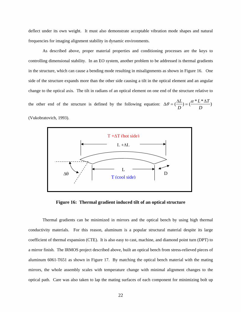
controlling dimensional stability. In an EO system, another problem to be addressed is thermal gradients
in the structure, which can cause a bending mode resulting in misalignments as shown in Figure 16. One
side of the structure expands more than the other side causing a tilt in the optical element and an angular
change to the optical axis. The tilt in radians of an optical element on one end of the structure relative to
the other end of the structure is defined by the following equation: )**()(D
TLDL ∆
=∆
=∆αθ
(Vukobratovich, 1993).
D
T +∆T (hot side)
LT (cool side)
∆θ
L +∆L
Figure 16: Thermal gradient induced tilt of an optical structure
Thermal gradients can be minimized in mirrors and the optical bench by using high thermal
conductivity materials. For this reason, aluminum is a popular structural material despite its large
coefficient of thermal expansion (CTE). It is also easy to cast, machine, and diamond point turn (DPT) to
a mirror finish. The IRMOS project described above, built an optical bench from stress-relieved pieces of
aluminum 6061-T651 as shown in Figure 17. By matching the optical bench material with the mating
mirrors, the whole assembly scales with temperature change with minimal alignment changes to the
optical path. Care was also taken to lap the mating surfaces of each component for minimizing bolt up
22

stresses. Match drilling and installation of pins were performed to keep surfaces from slipping during
transition to the cryogenic temperatures. The 230C (degrees Celsius) temperature-change test resulted in
the top and bottom plates holding parallelism of a few arc-seconds or near 10 µrad (Hylan, 2003). The
optical bench can be quite stable if the whole structure is one homogenous structure. Again, thermal
stress relief is necessary for optimum stability.
Figure 17: IRMOS aluminum optical bench [Hylan,2003] and example cast bench [Yoder,1990]
If all the components (structure and optics) are the same material and the optical system
experiences isothermal temperature changes, the result is only a scale change, provided the absence of
any residual stress (Vukobratovich, 1993). In the absence of residual stress relaxation, there is no
alignment change and no focus change for reflective optics attached to a matched material structure. This
is the basis for some retro-reflector designs, telescopes, and imagers. All-glass assemblies have been built
with special bonding techniques holding all the glass optics and glass structural pieces together. Glass
structures are fragile and expensive requiring special shock isolation mounting schemes. Glass tends to
have poor thermal conductivity and requires precautions to minimize gradients. All-glass assemblies,
with low CTE’s have proven to maintain stable alignment in the arc-second range over large temperature
23

swings, provided the gradients are allowed to stabilize. An all-metal optical assembly using matching
materials for structure and mirrors has been used successfully in space telescopes and cryogenic imagers
such as IRMOS.
It is difficult to design some electro-optical systems with entirely homogeneous component
materials. These reasons include needs for combinations of sensors and emitters with special components
like camera chips, cooled infrared focal plane arrays, laser media, laser components (polarizers, cavity
windows), beam splitters and filters. The use of matched materials for structure and mirrors can be used
for afocals, imagers, and beam expanders. When alignment stability is of most concern, the single
material optical assembly has shown to be the best performer over temperature.
The use of composites for optical benches is still being researched and perfected. For a
temperature-controlled environment, they offer superb stiffness to weight ratios and have been used in
space telescopes. Graphite composites are discouraged due to sensitivity to humidity. The structure can
absorb moisture and change dimensions (Yoder, 1993). A recent EO satellite sensor was built with a
telescope structure made of graphite cyanate ester composite material. It is has an extremely low CTE
and exhibits less moisture absorption than graphite epoxy. The whole structure was also temperature
controlled for “optimum” stability, however the verification of the stability requirements was not
presented (Henson, 1999).
24

Table 1: Properties of Common Mirror and Structural Materials at 300K [Paquin, 1999]
Selecting a structural material requires trade-offs like many other aspects of the design. Table 1,
shows some commonly used mirror and structural materials. Again, Invar is notorious for poor long-term
dimensional stability due to mechanical stress. It also has poor corrosion resistance and like many other
low CTE materials, exhibits larger thermal growths at temperatures away from room temperature. If a
high strength or stiffness to weight ratio is desired to reduce overall system weight, materials like
beryllium or silicon carbide (SiC) are often used. Beryllium is now expensive to fabricate, as one in ten
people are genetically susceptible to a terminal disorder if they breathe its dust. Fabrication shops have to
screen workers, and extra cost is incurred in the control and disposal of the material.
Silicon Carbide combines the two most important thermal features as it has a low CTE and high
thermal conductivity. Another feature of most importance is its dimensional stability. Based on its many
advantages, silicon carbide was selected as the material for the optical bench and mirrors in the
25

development of a satellite-based interferometer. The design requirements for each optical component
include an impressive, 1.2 µrad angular alignment stability over six years of design use from launch at
293 Kelvin through operation in space at 140 Kelvin. This design isolates the silicon carbide optical
bench and mirrors from the outer structure using six struts as shown Figure 18. The main mirrors will be
attached to the optical bench using brazing or Hydroxide Catalysis Bonding. Before launching, the
alignment stability will be tested in a cryogenic chamber (Veggel, 2005).
Figure 18: Common material (SiC) optical bench and primary mirrors with isolator struts [Veggel, 2005]
3 .3 .3 Opt ica l mount ing
A stable optical bench is the foundation for attaching and accurately holding optical elements.
For an EO system, the mounting of optical elements must only introduce minimal stress and provide a
stable, accurate mount when exposed to variations of vibration and temperature. Temperature cycling can
cause mount hardware to loosen or tighten on optical elements causing misalignments (Vukobratovich,
1993). This is typically a result of different CTE’s between the hardware and the substrate.
As discussed previously, designs should minimize bolt up stresses that can relax during thermal
changes. One way of improving the stability of joints involves quality-mating surfaces that are lapped,
polished, or diamond point turned. Adding pins to bolted joints or staking with epoxy can be used to
26
reduce slipping of two mating surfaces. Adequate pre-load on bolts or the use of spring, bellville, or
wave washers can maintain a clamping force and minimize shifts. It is speculated that the cause of some
hysteresis is due to redistribution of bolt-up stresses during temperature changes. A vibration cycle can
help re-distribute some residual stress.
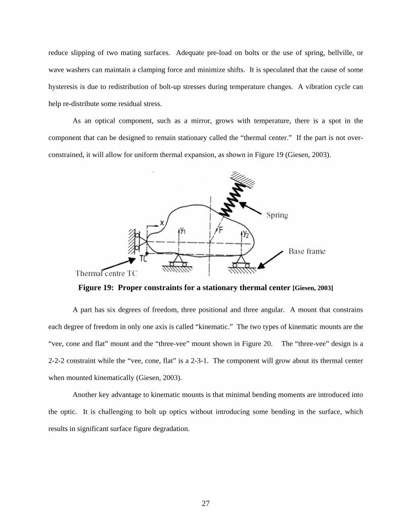
As an optical component, such as a mirror, grows with temperature, there is a spot in the
component that can be designed to remain stationary called the “thermal center.” If the part is not over-
constrained, it will allow for uniform thermal expansion, as shown in Figure 19 (Giesen, 2003).
Figure 19: Proper constraints for a stationary thermal center [Giesen, 2003]
A part has six degrees of freedom, three positional and three angular. A mount that constrains
each degree of freedom in only one axis is called “kinematic.” The two types of kinematic mounts are the
“vee, cone and flat” mount and the “three-vee” mount shown in Figure 20. The “three-vee” design is a
2-2-2 constraint while the “vee, cone, flat” is a 2-3-1. The component will grow about its thermal center
when mounted kinematically (Giesen, 2003).
Another key advantage to kinematic mounts is that minimal bending moments are introduced into
the optic. It is challenging to bolt up optics without introducing some bending in the surface, which
results in significant surface figure degradation.
27
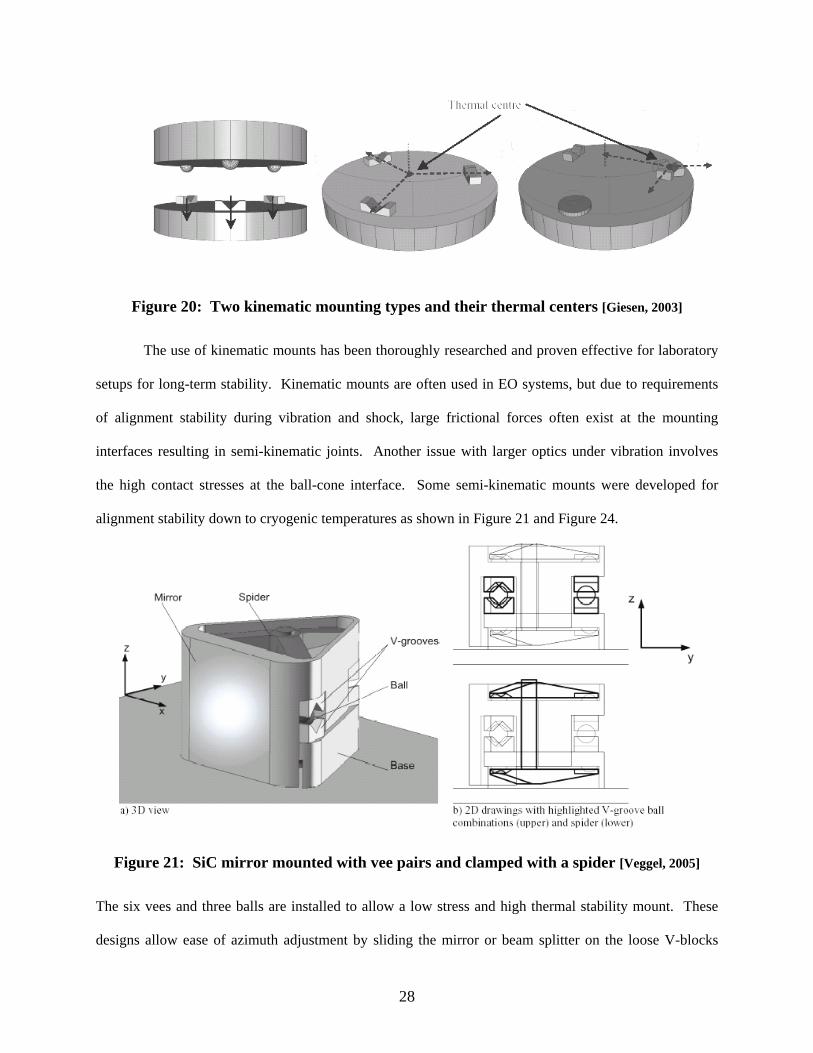
Figure 20: Two kinematic mounting types and their thermal centers [Giesen, 2003]
The use of kinematic mounts has been thoroughly researched and proven effective for laboratory
setups for long-term stability. Kinematic mounts are often used in EO systems, but due to requirements
of alignment stability during vibration and shock, large frictional forces often exist at the mounting
interfaces resulting in semi-kinematic joints. Another issue with larger optics under vibration involves
the high contact stresses at the ball-cone interface. Some semi-kinematic mounts were developed for
alignment stability down to cryogenic temperatures as shown in Figure 21 and Figure 24.
Figure 21: SiC mirror mounted with vee pairs and clamped with a spider [Veggel, 2005]
The six vees and three balls are installed to allow a low stress and high thermal stability mount. These
designs allow ease of azimuth adjustment by sliding the mirror or beam splitter on the loose V-blocks
28

before locking them down. When using kinematic mounts, there is a tendency for reduced heat transfer,
which is important for minimal thermal gradients. One method to improve heat transfer to the optic is to
use flexible copper braided straps from the base material to the optic. This is necessary when using high-
energy lasers where mirror surface heating occurs or when the optic is required to be kept cool for
improved thermal sensitivity.
Another proven method of mounting mirrors, for both stability over temperature and low stress in
the optical surfaces, involves making integral mounting features in the mirror substrate. A relief cut is
made in the mirror ears or exotic undercuts can be made using wire electrical discharge machining (EDM)
as shown in Figure 22. The tabs act as flexures to minimize the propagation of bolt up stress into the
mirror surface. Spacing the mounting flexure joint as far away from the optical surface as possible
further reduces stress-induced wavefront error.
Figure 22: Low stress, stable aluminum mirror mounting technique used in IRMOS [Hylan,2003]
29
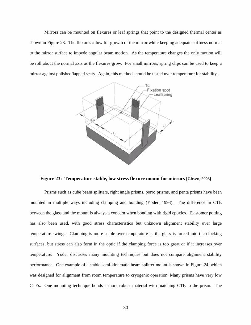
Mirrors can be mounted on flexures or leaf springs that point to the designed thermal center as
shown in Figure 23. The flexures allow for growth of the mirror while keeping adequate stiffness normal
to the mirror surface to impede angular beam motion. As the temperature changes the only motion will
be roll about the normal axis as the flexures grow. For small mirrors, spring clips can be used to keep a
mirror against polished/lapped seats. Again, this method should be tested over temperature for stability.
Figure 23: Temperature stable, low stress flexure mount for mirrors [Giesen, 2003]
Prisms such as cube beam splitters, right angle prisms, porro prisms, and penta prisms have been
mounted in multiple ways including clamping and bonding (Yoder, 1993). The difference in CTE
between the glass and the mount is always a concern when bonding with rigid epoxies. Elastomer potting
has also been used, with good stress characteristics but unknown alignment stability over large
temperature swings. Clamping is more stable over temperature as the glass is forced into the clocking
surfaces, but stress can also form in the optic if the clamping force is too great or if it increases over
temperature. Yoder discusses many mounting techniques but does not compare alignment stability
performance. One example of a stable semi-kinematic beam splitter mount is shown in Figure 24, which
was designed for alignment from room temperature to cryogenic operation. Many prisms have very low
CTEs. One mounting technique bonds a more robust material with matching CTE to the prism. The
30

matching material can then be mounted using kinematic techniques. Care must be made to use very thin
bond lines as epoxy shrinks as it cures.
Figure 24: Thermally stable mount for a prism beam splitter [Veggel, 2005]
Lenses, like a majority of optics require special mounting in order to keep stress levels below
distortion thresholds and keep stable alignment over temperature. The common retaining ring method of
clamping a lens with a threaded retainer can cause problems over temperature as shown in lower left
corner of Figure 25. For hot temperature, the lens seat grows and could allow the clamping force to go to
zero, which would allow the lens to de-center, causing misalignments (Yoder, 1999). The initial pre-load
on the lens has to be high enough to stop the release of the lens at hot. One concern at cold temperatures
is that the lens mount shrinks to the point of high stress concentrations causing risk of lens fracture.
Yoder notes that a spring can be used to hold a lens into a seat, but as with any type of mount, should be
tested for alignment stability using temperature and vibration tests. Another method of mounting lenses
that eliminates stress over temperature is an elastomer mounting. The lens is centered using shims and is
set in a seat while potting is injected around the gap between the lens and the lens barrel. Lens mounting
alignment stability should be tested using surrogate mirrors or special fixtures and equipment.
31

Figure 25: Various lens mounting techniques [adapted from Yoder, 1999]
For many IR applications, the crystal material used for lenses can possess allowable stress levels
much lower than normal optical glass. A unique, alignment stable and low stress mount was developed
for a 4-inch diameter cryogenic lithium fluoride optic (Kvamme, 2005). It uses a flexure ring as shown in
Figure 26, which allows axial and radial compliance over temperature. The titanium (Ti-6Al-4V) ring
centers the lens with its radial diamond flexures. Attached to the ring were axial flexures to keep the lens
clamped in the normal direction as shown in Figure 27.
32
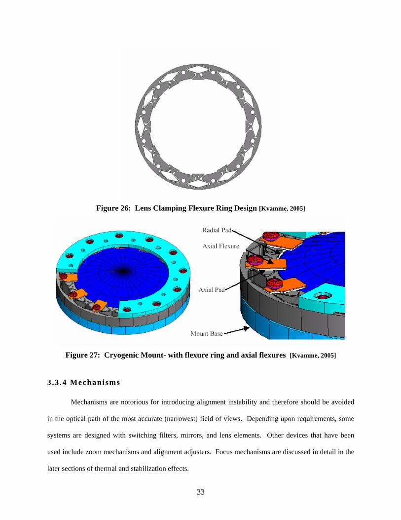
Figure 26: Lens Clamping Flexure Ring Design [Kvamme, 2005]
Figure 27: Cryogenic Mount- with flexure ring and axial flexures [Kvamme, 2005]
3.3 .4 Mechanisms
Mechanisms are notorious for introducing alignment instability and therefore should be avoided
in the optical path of the most accurate (narrowest) field of views. Depending upon requirements, some
systems are designed with switching filters, mirrors, and lens elements. Other devices that have been
used include zoom mechanisms and alignment adjusters. Focus mechanisms are discussed in detail in the
later sections of thermal and stabilization effects.
33

Filter wheels, lens switchers, and flipper mirror mechanisms are the most common electro optical
system mechanisms. The positional repeatability over temperature is critical for boresight alignment and
image quality. A cryogenic application drove the design of the grating and filter wheels shown in Figure
28. These devices have a 4 arc-second (20 µrad) repeatability. The wheel position is clocked by a spring-
loaded ratchet, which locates two roller bearings (Hofferbert, 2003). Lens switchers can be mounted on a
similar rotary design or on a flipper arm. With flipper arm designs, the stop or device for keeping the lens
when in place will expand with temperature. This growth must stay within alignment stability tolerance,
but is not an issue for uniform material construction. The central rotary joint is also susceptible to angular
drift, and when two bearings are used, the same support material must be used on both sides of the wheel.
Again, it is desired to keep all movable components out of the optical path of the most accurate sensor or
field of view and then switch in elements for a slightly less stable alignment.
Figure 28: Cryogenic filter and grating wheels [Hofferbert, 2003]
Zoom mechanisms are prone to alignment shifts when zooming as well as over temperature. The
typical zoom lens configuration uses a linear slide or barrel to translate lens elements. The chief optical
ray of the system must be parallel to the linear travel for accurate alignment. In order to minimize
34
friction, dissimilar metals are introduced into the design. This can lead to mismatches in the thermal
coefficients of expansion and alignment instability over temperature.
In optical layouts, some components can be roughly aligned using pins and machined registration
pads. Fine mechanical alignment of the optical axis is required in many systems as well as a method to
lock the adjustment for normal operation. Some locking mechanisms can compromise the fine alignment.
Also, the adjustment mechanism is typically a different material than the mount and will expand
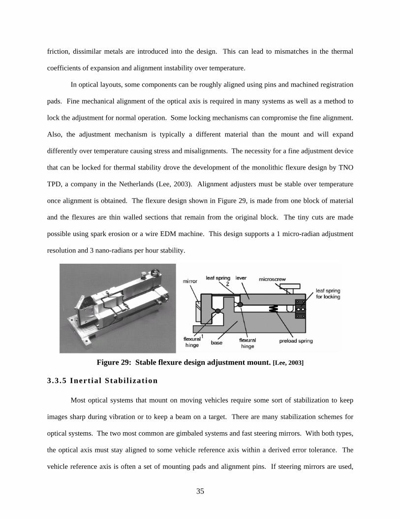
differently over temperature causing stress and misalignments. The necessity for a fine adjustment device
that can be locked for thermal stability drove the development of the monolithic flexure design by TNO
TPD, a company in the Netherlands (Lee, 2003). Alignment adjusters must be stable over temperature
once alignment is obtained. The flexure design shown in Figure 29, is made from one block of material
and the flexures are thin walled sections that remain from the original block. The tiny cuts are made
possible using spark erosion or a wire EDM machine. This design supports a 1 micro-radian adjustment
resolution and 3 nano-radians per hour stability.
Figure 29: Stable flexure design adjustment mount. [Lee, 2003]
3 .3 .5 Inert ia l Stabi l izat ion
Most optical systems that mount on moving vehicles require some sort of stabilization to keep
images sharp during vibration or to keep a beam on a target. There are many stabilization schemes for
optical systems. The two most common are gimbaled systems and fast steering mirrors. With both types,
the optical axis must stay aligned to some vehicle reference axis within a derived error tolerance. The
vehicle reference axis is often a set of mounting pads and alignment pins. If steering mirrors are used,
35

each optical path containing a steering mirror is susceptible to alignment drift over temperature due to the
mirror’s commanded position error.
When designing the stabilization system for optimum optical alignment retention, one important
design parameter is the temperature drift of the feedback position sensors. Some gimbaled systems and
steering mirror designs have linear position sensors for measuring small angles, and resolvers for
measuring larger travel angles. It is important that the positional accuracy of the optical axis be measured
and commanded within specifications over the operating temperature range. If a steering mirror’s
position sensor drift is a problem there are several ways of taking out the mirror drift. These include a
beam alignment feedback control system, mirror reference calibration, and thermal drift calibration.
According to Mitchell, “a fast steering mirror consists of six elements: voice cool actuators, mirror
suspension, internal position feedback sensors, mirror, drive electronics, and a frame” as shown in Figure
30 (2001). The frame that holds the position sensors (differential impedance transducers, DIT) must be
stable over temperature, as the mirror will be positioned relative to the feedback sensor’s “sensed”
position.
Figure 30: Fast Steering Mirror [Mitchell, 2001]
36
3.4 Thermal Des ign
The operational use of electro-optical systems dictates the need for thermal design and thermal
management. EO systems vary in application from tank sights and airborne cameras to space telescopes.
However, the focus of this discussion involves systems that operate inside the earth’s atmosphere over
temperatures of +71C to –54C.
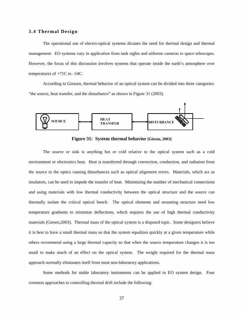
According to Giessen, thermal behavior of an optical system can be divided into three categories:
“the source, heat transfer, and the disturbance” as shown in Figure 31 (2003).
Figure 31: System thermal behavior [Giesen, 2003]
The source or sink is anything hot or cold relative to the optical system such as a cold
environment or electronics heat. Heat is transferred through convection, conduction, and radiation from
the source to the optics causing disturbances such as optical alignment errors. Materials, which act as
insulators, can be used to impede the transfer of heat. Minimizing the number of mechanical connections
and using materials with low thermal conductivity between the optical structure and the source can
thermally isolate the critical optical bench. The optical elements and mounting structure need low
temperature gradients to minimize deflections, which requires the use of high thermal conductivity
materials (Giesen,2003). Thermal mass of the optical system is a disputed topic. Some designers believe
it is best to have a small thermal mass so that the system equalizes quickly at a given temperature while
others recommend using a large thermal capacity so that when the source temperature changes it is too
small to make much of an effect on the optical system. The weight required for the thermal mass
approach normally eliminates itself from most non-laboratory applications.
Some methods for stable laboratory instruments can be applied to EO system design. Four
common approaches to controlling thermal drift include the following:
37

1. Control environment surrounding optics and structure
2. Control the thermal state of the structure with insulation
3. Minimize gradients in the structure
4. Try to use materials with low or the same CTE (Ridgway)
Thermal modeling is useful for insuring heat loads are removed efficiently from the EO system.
Thermal gradient analysis is the most important modeling for alignment stability. If gradients are
reduced, alignments will improve. The thermo-elastic finite element analysis tools currently available
cannot accurately predict alignment drift of optical assemblies with micro-radian resolution due to many
uncertainties including residual stresses, bolted-joint slip, inhomogeneous CTE in the material, and
unknown angular mirror/potting interaction.
3.4 .1 Hot Temperature Extremes
Many optical systems are required to function at military standard temperatures of 55 degrees
Celsius. Without cooling, internal temperatures can quickly exceed acceptable operating range of most
electronic chips. The amount of cooling needed to dissipate a given heat load is relatively easy to model.
However, choosing the best method of removing the heat without impacting optical alignments is more
difficult.
Heat sources in optical systems include circuit card assemblies such as a power supply, video
processing, system controllers, and laser controller. Other heat sources include lasing heat, infrared
coolers, motors, gyros, etc. Other sources include ambient heat loads such as solar radiation, vehicle heat,
and aerodynamic heating. All of these heat sources build up an internal system temperature gradient.
Ideally the system would be designed to minimize this gradient. Using structural materials such as
aluminum, which are good thermal conductors, minimizes gradient effects. By minimizing the operating
temperature gradient, the change in optical alignment is also minimized from initial turn-on to steady state
operation. As gradients form, the optical bench warps causing misalignments. Another way to minimize
the internal gradient across the structure is to provide plenty of air channels with fans to circulate air. Just
38

minimizing the gradient does not however dissipate the buildup of electronics heat to the outside world.
Isolating the heat sources from the optical elements is difficult in common structure EO systems, where
the optics share the same conduction path. If alignment stability is paramount to the design, the trade-off
of a thermally isolated optics bench with insulation and low conduction interface mounts should be
considered.
Typical methods of heat removal include liquid cooling, cold-wall heat exchangers, air-to-air heat
exchanger, and constant temperature conditioned air via ducts. The most efficient is liquid cooling but it
has many drawbacks including susceptibility to leaks and corrosion. Cold-walls are structural walls
constructed with fin-stock or hollow portions for circulating outside air with a fan. These are attractive
when a low profile heat exchanger is needed, as it can serve both purposes of structure and heat removal.
One downside to using cold-walls is the loss of heat at cold temperatures. Another drawback with cold
walls is the change in internal gradient of the optical structure when air is forced through the cold-walls.
This gradient change can cause skewing of optical alignments unless they are thermally or structurally
isolated from the cold-wall. The affects can be reduced with tight control of the fan based on temperature
of the cold-walls, but at high temperatures, the fan will likely need to run continuously to dissipate the
heat.
The two most “alignment friendly” methods of heat dissipation from an electro-optics assembly
are air-to-air heat exchangers and piped-in conditioned air. In order to succeed, both of these methods
need stirring fans and air volume around the optical components. With air-to-air heat exchangers, outside
air is brought through one side of the heat exchanger and optical system air is brought through the other
side. This method has efficiency issues but has an advantageous ability to slowly change the internal
environment. This minimizes external ambient changes from inducing rapid internal gradients in the
optical system. One downside to the air-to-air heat exchanger is the large volume that may be required to
dissipate the heat. If the luxury of conditioned air is available, the optical system can approach the most
stable “lab-like” performance with excellent alignment retention. Keeping all the optical system at one
temperature is a desired goal, but minimizing the temperature gradients of the components is most
39

important. Furthermore, if the system is made using reflective optics with matching structural materials,
gradients are the only thermal concern to the optical alignment.
After trying to minimize the temperature gradient across the optical system, the next goal for
stable alignment would be to maintain whatever gradient exists. This means that the steady state gradient
at one ambient temperature should remain unchanged at any ambient temperature. Thermal management
and “alignment friendly” heat dissipation methods are required to maintain a constant temperature
gradient. This same philosophy applies to cold temperature design as well.
Lasers are notorious for producing a great amount of heat. This is mostly attributed to the low
efficiency of photons out/unit input energy. Some high power laser systems use a flash lamp around the
lasing rod. The flash lamp heats up very rapidly and requires quick heat dissipation, most often by means
of a pumped liquid coolant. The coolant system is routed to a heat exchanger, which either brings in
outside air or optical system enclosure air. Laser assemblies are normally purchased items, which are
integrated with other optical systems. These lasers should have performance specifications including
alignment retention over temperature. Those with tight alignment specs have the coolant system
thermally isolated from the rest of the laser optics. This allows minimal laser beam wander as the coolant
heats up during firing.
3.4 .2 Cold Temperature Extremes
Many optical systems are required to power up after a -40 degrees Celsius soak as well as operate
in a -55 degrees Celsius ambient. Anytime an electro-optical system is “cold soaked” with power off, all
operating induced gradients dissipate. There is a warm-up time or settling time required for optical
alignment to stabilize. This stability settling time increases if heaters are needed to bring some
components to a safe operating temperature. Experience has shown that the use of heaters should be
accomplished prudently. The more heaters are used, the more the internal temperature gradient is
modified from normal operation, causing unwanted drifts in the optical alignment.
40
Often, commercial parts or design issues dictate the selection of components that cannot function
at -40C. These problems are overcome with heaters but caution should be made to keep optical alignment
stability in the forefront of the design process. Experience has shown that resistive coil heater fans can
cause extreme gradients, which cause alignment degradation especially if the volume of air is small. The
fan must have an adequate air volume and flow channels in order to uniformly heat the structure. If the
optical structure requires heating for the operation of certain components, the optical structure should be
thermally isolated from any cold external structure. In addition, small volumes of air can heat rapidly and
locally distort optics causing the wedge effect in lenses and windows. Another alternative, though not
ideal, involves optimizing the use of resistive heater elements that are mounted to problematic
components. If the components are thermally isolated from the optical bench or main structure, localized
heating can be performed efficiently with resistive strip heaters. Care should be taken to tightly control
the strip heater’s dissipation to maintain constant temperatures.
Many lasers will not function at temperatures as cold as –40C. Some reasons include internal
condensation or increased viscosity of the coolant. The internal condensation problem is a design
constraint because dry air can cause the build up of a static charge and open up the pockel cell too early
before energy is adequately built up in the laser cavity. A warm-up period can be allotted for the laser
system after soaking at cold temperatures. In order to keep a stable alignment, the laser’s heaters need to
be controlled. The initial warm-up will cause poor alignment as gradients form across the optical
structure but the alignment will settle out upon steady state cycling of the heaters about a control point.
This settling time for the optimum alignment of the optical axis to stabilize, can take thirty minutes to
several hours depending on the thermal conductivity of the laser structure.
Another thermal concern for lasers with coolant/air heat exchangers is the over-chilling of the
coolant at cold temperatures causing the temperature of the laser rod to plummet. If the laser rod’s
temperature drops below the dew point of the resonator cavity, the rod ends fog. If the coolant system is
thermally isolated from the rest of the optics, the coolant can be heated without affecting optical
41
alignment. The coolant should be kept warm enough to eliminate fogging events but cool enough for
energy efficiency, so the next lasing event occurs without having to immediately get rid of heat.
Thermal management is a key player in the stability of optical alignments in EO systems exposed
to environmental temperature changes. It is difficult to evenly warm an optical assembly when it is
thermally tied to an outer coldwall. The gradient can be made worse with the absence of air channels to
circulate heated air. Some systems have shown improved alignment stability when heaters were kept off
and the internal to external temperature gradient was allowed to remain nearly constant over temperature.
One of the most advantageous designs for keeping two sensors or a sensor and a laser aligned is the
common isolated optical bench method. With this design, all components mount to a rigid structure that
is thermally isolated from the outer cold enclosure. With plenty of air volume, vibration isolated stirring
fans, and small heater coils or conditioned air, the whole system, including cold sensitive parts, can be
kept warm without adding a harsh gradient to the optical system. Again, keeping everything at a constant
temperature or a constant/minimal gradient across the structure has proven to minimize alignment drift.
For some EO systems, the environmental temperature swing is too great to feasibly maintain a single
internal temperature so the best approach is to limit the internal temperature swing. If this can be
accomplished without changing the gradient across the structure, it is more likely to improve alignment
stability.
3.4 .3 Thermal Effects on Optical Elements
Changing temperature of optical elements can cause several problems unrelated to the structure or
mount. One problem is the change in optical properties of lenses and windows over temperature causing
defocus and potential alignment error. Another problem is the formation of condensation on optics,
rendering the sensor or laser ineffective to the operator. Several methods have been used to negate these
thermal effects.
The index of refraction (n) for optical materials varies with temperature. This change in index
per degree Kelvin is known as the therm-optic coefficient. The new index, n’ is given by the equation:
42
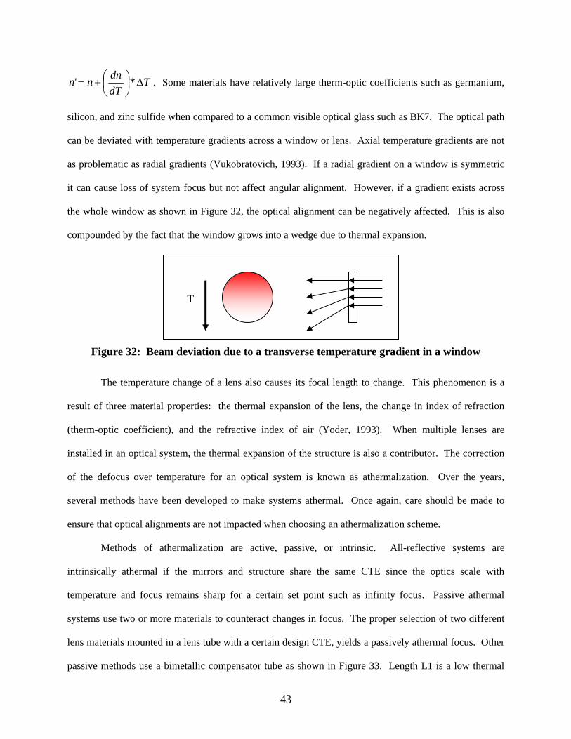
TdTdnnn ∆⎟
⎠⎞
⎜⎝⎛+= *' . Some materials have relatively large therm-optic coefficients such as germanium,
silicon, and zinc sulfide when compared to a common visible optical glass such as BK7. The optical path
can be deviated with temperature gradients across a window or lens. Axial temperature gradients are not
as problematic as radial gradients (Vukobratovich, 1993). If a radial gradient on a window is symmetric
it can cause loss of system focus but not affect angular alignment. However, if a gradient exists across
the whole window as shown in Figure 32, the optical alignment can be negatively affected. This is also
compounded by the fact that the window grows into a wedge due to thermal expansion.
T
Figure 32: Beam deviation due to a transverse temperature gradient in a window
The temperature change of a lens also causes its focal length to change. This phenomenon is a
result of three material properties: the thermal expansion of the lens, the change in index of refraction
(therm-optic coefficient), and the refractive index of air (Yoder, 1993). When multiple lenses are
installed in an optical system, the thermal expansion of the structure is also a contributor. The correction
of the defocus over temperature for an optical system is known as athermalization. Over the years,
several methods have been developed to make systems athermal. Once again, care should be made to
ensure that optical alignments are not impacted when choosing an athermalization scheme.
Methods of athermalization are active, passive, or intrinsic. All-reflective systems are
intrinsically athermal if the mirrors and structure share the same CTE since the optics scale with
temperature and focus remains sharp for a certain set point such as infinity focus. Passive athermal
systems use two or more materials to counteract changes in focus. The proper selection of two different
lens materials mounted in a lens tube with a certain design CTE, yields a passively athermal focus. Other
passive methods use a bimetallic compensator tube as shown in Figure 33. Length L1 is a low thermal
43
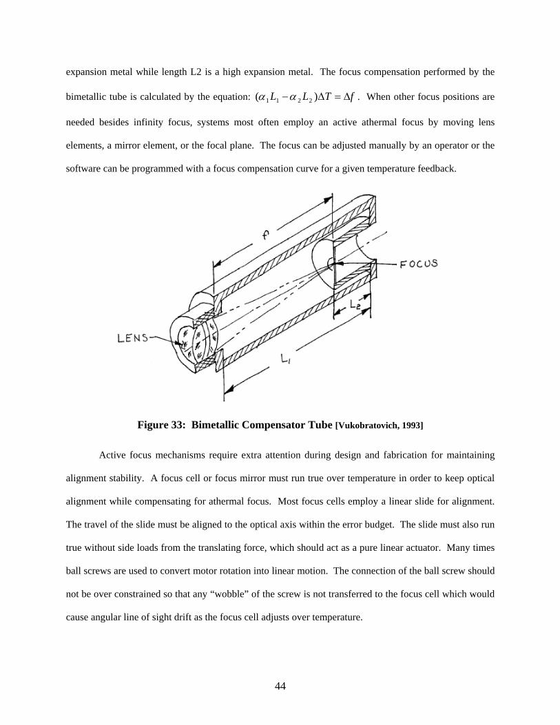
expansion metal while length L2 is a high expansion metal. The focus compensation performed by the
bimetallic tube is calculated by the equation: . When other focus positions are
needed besides infinity focus, systems most often employ an active athermal focus by moving lens
elements, a mirror element, or the focal plane. The focus can be adjusted manually by an operator or the
software can be programmed with a focus compensation curve for a given temperature feedback.
fTLL ∆=∆− )( 2211 αα
Figure 33: Bimetallic Compensator Tube [Vukobratovich, 1993]
Active focus mechanisms require extra attention during design and fabrication for maintaining
alignment stability. A focus cell or focus mirror must run true over temperature in order to keep optical
alignment while compensating for athermal focus. Most focus cells employ a linear slide for alignment.
The travel of the slide must be aligned to the optical axis within the error budget. The slide must also run
true without side loads from the translating force, which should act as a pure linear actuator. Many times
ball screws are used to convert motor rotation into linear motion. The connection of the ball screw should
not be over constrained so that any “wobble” of the screw is not transferred to the focus cell which would
cause angular line of sight drift as the focus cell adjusts over temperature.
44

Any time that optics are required to operate over a range of temperatures, there exists a risk of
condensation as the optic’s temperature falls below the dew point. Most electro-optical systems are
sealed in an enclosure to keep out dust and water. For enclosures with no moving parts, it can be easier to
seal to keep out water vapor. The main areas for fogging concerns are optical windows that get colder
than the surrounding structure that is typically warmer due to electronic heat sources. Several methods
have been used to eliminate the formation of condensation or remove it once the formation begins. Each
method has its benefits, but most have a negative impact on optical alignments.
The dew point of the air inside the sensor pod or housing is the temperature required for
condensate form, for a given relative humidity. To eliminate fogging, the temperature of the optical
windows are either kept above the dew point by using heat or the dew point of the air is lowered by
keeping the air dry. Adding heat to windows causes temperature gradients, which causes optical path
deformation. If the window is circular, the window can have a radial resistive heater bonded to its edge
and only cause a focus change that is acceptable for systems with active focus. However, this could be
detrimental to an infrared system that senses temperature gradients in the optics. Another method of
heating the window surface is blowing warm air across the window, which causes transverse thermal
gradients as discussed earlier. If the optical axis deviation caused by a window heater is within the
alignment stability budget, this option is a low maintenance approach. Another method, utilizing a
desiccant material inside an EO pod will dry out the air to eliminate fogging events without impacting the
optical alignment. The downside is that the material eventually saturates and requires periodic changing.
If dry nitrogen is available on the vehicle, a slow purge can also work to keep a dry environment with no
impact to optical path provided a pressure relief is used; windows could deflect under pressure stresses.
Many EO systems have moving gimbals with seals that are difficult to seal. Those systems that are well-
sealed can still be evacuated and back filled with dry nitrogen. However, they may still be plagued by
vapor intrusion.
45

CHAPTER IV ALIGNMENT STABILITY TEST METHODS AND EQUIPMENT
4.1 Test Equipment
During the design phase of components and upon system completion, the performance of
alignment drift requires testing and validation. For checking alignment stability of EO systems,
collimators and auto-collimators are two valuable pieces of test equipment. These instruments must be
used outside a special environmental temperature chamber with a window to transmit desired
wavelengths.
For use with multiple wavelengths such as visible, mid-wave infrared, and near IR laser
wavelengths, a reflective collimator is required (Dickey, 1980). A simple collimator consists of two
components, an off-axis paraboloidal mirror and a target that is positioned at the focal point of the mirror
as shown in Figure 34. The projected light rays coming from the target are converted into collimated or
parallel rays of light, hence the name “collimator.”
Figure 34: Collimator for testing optical alignments of an EO system. [Dickey,1980]
If a laser is fired at the parabola and roughly parallel to the collimator axis, it will go through
focus near the focal plane of the collimator. High power lasers should be attenuated to impede damage to
the target. The parabola mirror should be large enough to cover all sensor apertures that need tested, as
shown in Figure 35. For space constraints, collimators can be a folded design with added flat mirrors or
the design can employ two mirrors with power.
46

Figure 35: Collimator primary mirror aperture coverage - for apertures of an EO system [Dickey,1980]
Most often the focal plane allows for the accurate placement of different targets. The target can
be a pinhole that is backlit with a light or thermal source. The pinhole target serves as a common
reference for checking the alignment of multiple sensors in an EO system. Laser to sensor alignment or
boresight can be checked by firing the raw or an attenuated amount of the laser energy at a target of
desired material in the collimator and can be viewed simultaneously by the sensor. Laser targets include
heat absorbing glass, ceramics, flashing phosphor, or Polaroid film depending upon the sensor and laser
combination. Placement accuracy of the target in the focal plane of the collimating mirror is critical to
alignment accuracy. According to Dickey’s optical ray trace analysis, for a 1.5 m focal length collimator
and a certain laser to sensor axis separation, a 0.50 mm target placement error (defocus) causes a
boresight error of 35 µrad or a sensitivity of 70 µrad/mm defocus. The error sensitivity to defocus
depends upon the focal length and separation distance of the two optical axes (laser and sensor). Accurate
determination of the collimator’s focal point can be determined with interferometry and is indeed critical
for testing alignment accuracy of multiple sensors and lasers with different apertures (Dickey, 1980).
Autocollimators are another tool required for measuring alignment accuracy and stability. An
autocollimator emits collimated light and requires a return of collimated light. It is used to measure small
47

angular deviations of a flat mirror as seen in Figure 36. Visible autocollimators project a target and the
return target is imaged in an eyepiece for viewing. When the autocollimator is aligned with the mirror,
the return target is aligned with the reference reticle, as shown in Figure 37. Commercial autocollimators
such as the Nikon 6D have measurement accuracy of 2 arc-seconds with vernier resolution of 0.5 arc-
seconds, however even when an operator has good eyesight and repeatable placement of the eye in the
aperture, 1 to 2 arc-seconds resolution/repeatability is hard to achieve. When combined with a video
camera and a 12.5 mm focal length, FL imaging lens, a commercial visible autocollimator can achieve a
measurement resolution near 1.5 arc-sec. Resolution can be improved with longer focal length camera
lenses, but it decreases the field of view resulting in a loss of total measurement range. The 50 mm
aperture of the Nikon 6D, allows viewing of two mirror surfaces simultaneously and seeing two sets of
returns, which is essential to testing optical alignment stability of one mirror with respect to another.
Software is available to analyze images from cameras looking at visible autocollimator return reticles
(Zona, 2001).
Figure 36: Autocollimator Schematic [Leviton, 2003]
48

Figure 37: Visible Autocollimator - a) return image aligned with autocollimator axis, b)
mirror is tipped 1 unit in elevation and 2 units in azimuth [Leviton, 2003]
Electronic autocollimators use a laser diode and a quadrature detector to sense the location of the
return beam as shown in Figure 38. The output of the unit is a nearly collimated laser beam and
sometimes polarized. Electronic autocollimators are good for measuring deflections of a mirror during
vibration where high bandwidth measurements are required, with commercially available sampling up to
1 kHz and resolution of 0.01 arc-sec. However, electronic autocollimators can be difficult to use for long
stability measurements as they can suffer from electronic drift and slight changes in room temperature.
Most electronic autocollimators suffer from poor signal to noise with lower reflectivity mirrors and any
change in polarization when reflecting off of fold mirrors with various coatings at a 45-degree angle of
incidence. The output beam of some laser autocollimators have a good beam quality and can be used as
laser sources for other tests.
49

Figure 38: Quadrature detector used inside electronic autocollimators and beam position measurement devices [Hane , 2003]
In order to check alignment stability over temperature, the unit under test (UUT) is placed in a
special temperature chamber. The UUT can be a system component or the whole system. The chamber
must have an optical window for passing wavelengths under test, to and from the measurement
equipment, which is held stable at room temperature. The window exposed to the lab environment will
fog as the window temperature falls below the dew point of lab air. This problem can be solved several
ways. One way is to use two windows and flow dry nitrogen between the two windows or purge the
volume between the two windows as shown in Figure 39. This can keep the outside window warm
enough to keep from fogging. Another method uses a dry nitrogen purged box surrounding the window
with a port that is removed for the short time during data collection. To keep the windows from affecting
the measurement, the radial gradient must be minimized. Air must not flow directly on the surface of the
window or problematic gradients form and steer the optical axis. For tests involving temperatures down
to –65C, chilled air chambers are used. For cryogenic vacuum temperature tests, the air is evacuated from
the chamber, and the UUT is cooled through radiation, using a chilled wall.
50

Figure 39: Temperature Chamber Setup [Zona, 2001]
4 .2 Variabi l i ty
In order to take meaningful data of the alignment stability, several variables must be controlled.
As previously discussed, the measurement is sensitive to air blowing across the chamber window.
Another variable that must be controlled is the laboratory temperature, as some equipment and
components can be sensitive to small air temperature fluctuations or air currents blowing across the setup.
The ramp rate of the temperature chamber must duplicate operational cases. If the ramp rate is very steep,
the thermal shock could induce some alignment changes uncharacteristic of real world conditions. Some
data can be taken during transitions, but repeatability is better if the UUT temperature is stabilized to a
small rate of change prior to measurement of alignment error. Air currents in the chamber can cause
wavefront error in the optical path due to refraction and can affect the ability to measure as the image
“fuzzes” out of focus. This can be improved by turning off the air circulator of the temperature chamber
(Zona, 2001). Air currents with temperature gradients in the optical path external to the chamber can also
cause image degradation and measurement noise. This can be improved by using two or three windows
with airspace purged with temperature-controlled dry air. The temperature of the airspace needs to be the
average temperature of the air on either side of the window. Finally, a cardboard tube around the optical
path can reduce air currents that negatively affect the measurement of an autocollimator.
51

Alignment stability is a measure of the angle between one optical path and a reference datum, or
it is an angle measurement of the alignment of two optical paths. Collected stability data typically shows
shift and drift. Drift is the change of alignment angle as a function of temperature, but shift is when an
alignment does not return to the same place after undergoing identical thermal cycles. The shift is known
as hysteresis as shown in Figure 40. It is difficult to tell whether hysteresis is induced by the test setup or
it is issue within the UUT. Tests should be repeated several times to gain confidence in the equipment
and measurement capability. Reference mirror tests can be designed to verify test setup variability and
set a bound for the measurement uncertainty.
Figure 40: Alignment Drift and Shift [Wilson, 2005]
4.3 Example System Test Methods
The collimator is a widely used piece of equipment for testing electro-optical systems. It presents
targets at an “infinity” system focus for simulating long-range targets. The collimator can be used outside
a temperature chamber for measuring system performance over temperature.
52

4.3 .1 Sensor-to-sensor a l ignment s tabi l i ty
Many electro-optical systems have two or more sensors such as color television and infrared
cameras that must stay aligned. A common target must be presented to both sensors in the collimator.
This is normally a pinhole target backlit with a light bulb, which emits both visible and infrared energy.
At each temperature step, the location of the pinhole target in the FOV of each target is recorded. There
are multiple ways to find the location of a bright spot through onboard video tracking or just collecting
image captures and post processing. The pixel location of the bright intensity spot centroid in each sensor
can be subtracted to give the alignment between sensors. The measure of how this alignment changes
over temperature is called sensor-to-sensor alignment stability. It can be converted from the pixel
measurement to its angular equivalent by knowing the angular pixel spacing of the sensor. If data is not
taken from each sensor simultaneously, care must be taken to not change the alignment of the whole
electro-optical system or the collimator during the measurement time of each sensor at a particular
temperature data point. Between data points, changes in the alignment of the system or collimator do not
impact the measurement of sensor-to-sensor or laser-to-sensor alignment.
4.3 .2 Laser- to-sensor a l ignment s tabi l i ty
As discussed before, the collimator located outside a temperature chamber can be used to
measure the alignment error between a pulsed laser and a sensor in an electro-optical system. Over
temperature, the laser can be fired at a target material, which allows the sensor to view the alignment
error. This method works well for checking laser alignment to an infrared sensor by using heat-absorbing
glass at the focal plane of the collimator. With each laser pulse, a hot spot forms on the target. This hot
spot can be tracked using a flashing spot video tracker or can be post processed through image captures.
The measured alignment error is the number of pixels between the laser hot spot and the aiming reference,
which is most often a reticle or “cross-hairs”. If a target material is not available for the sensor to view, a
hole can be punched in a thin film target that is backlit by a source the sensor can see (Dickey, 1980).
53
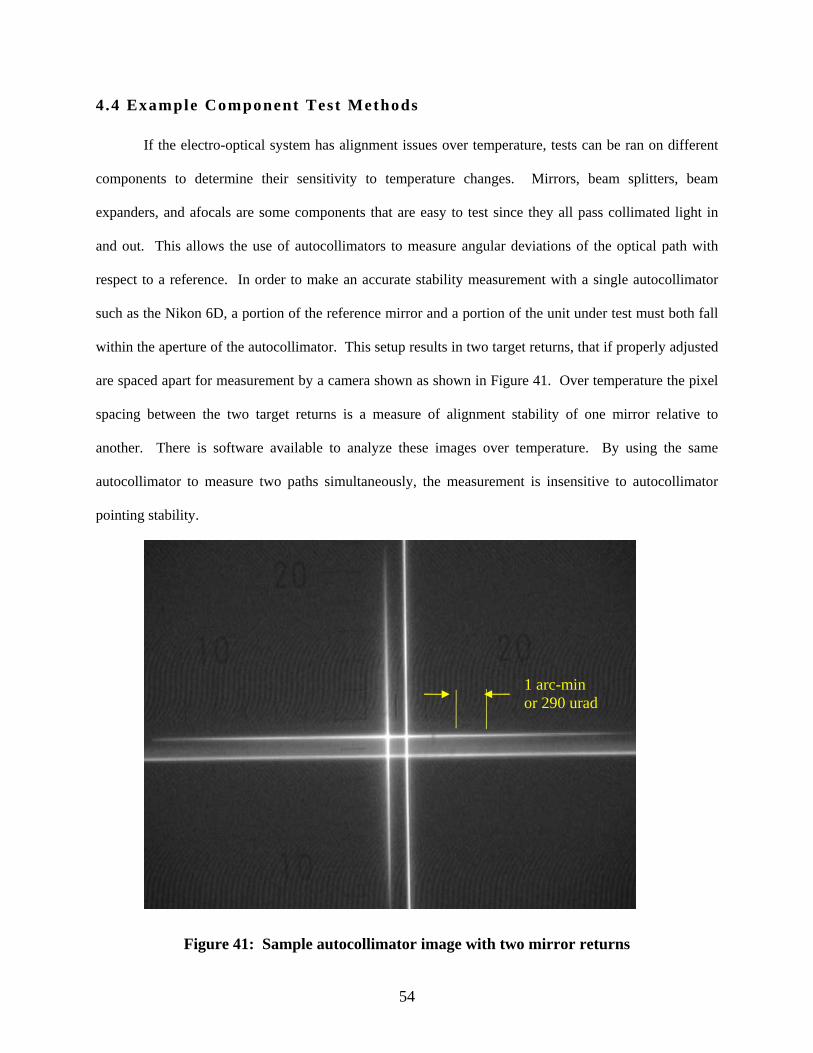
4.4 Example Component Test Methods
If the electro-optical system has alignment issues over temperature, tests can be ran on different
components to determine their sensitivity to temperature changes. Mirrors, beam splitters, beam
expanders, and afocals are some components that are easy to test since they all pass collimated light in
and out. This allows the use of autocollimators to measure angular deviations of the optical path with
respect to a reference. In order to make an accurate stability measurement with a single autocollimator
such as the Nikon 6D, a portion of the reference mirror and a portion of the unit under test must both fall
within the aperture of the autocollimator. This setup results in two target returns, that if properly adjusted
are spaced apart for measurement by a camera shown as shown in Figure 41. Over temperature the pixel
spacing between the two target returns is a measure of alignment stability of one mirror relative to
another. There is software available to analyze these images over temperature. By using the same
autocollimator to measure two paths simultaneously, the measurement is insensitive to autocollimator
pointing stability.
1 arc-min or 290 urad
Figure 41: Sample autocollimator image with two mirror returns
54

A stable reference mirror must be used for making accurate measurements. By choosing an
aluminum or silicon carbide fixture material, a reference mirror can be diamond point turned right on the
fixture, which guarantees a stable reference, as shown in Figure 42. The test fixture holds the unit under
test (UUT) over temperature, and should mimic the mounting method found inside the electro-optical
system.
Figure 42: Example of a component test fixture [Zona, 2001]
Individual flat mirrors or steering mirrors can be tested in their mounts by attaching the mount
directly to the back of a DPT reference mirror, as shown in Figure 43. Two mirror returns allow relative
alignment to be checked with one autocollimator. Beam splitters act as mirrors for part of the split and
can be tested similar to a flat mirror. If lens mounting techniques need tested, a glass surrogate mirror can
be fabricated with the same external shape except with a flat surface in the center that is silver coated for
getting an autocollimator return.
55

Mirror (UUT) DPT Reference Mirror Fixture
Figure 43: Alignment stability test fixture for single autocollimator measurement
For testing beam expanders and afocals, a return mirror must be built into the fixture as well as a
reference mirror. A portion of the autocollimator views the reference, while another portion views the
optical path down and back through the beam expander as shown in Figure 44.
56
AutocollimatorWindow
Fixture in chamber
UUT) Reference mirror and return mirror Beam expander or afocal (
Figure 44: Alignment stability testing of a beam expander using single autocollimator

If the two test apertures are spaced outside the aperture of a single visible autocollimator, two
autocollimators can be used, with a common reference mirror to take out any alignment changes between
autocollimators or of the rigid body motion of the two optical paths as a whole. Each autocollimator
aperture floods the common autocollimator reference and the measurement axes. The data collected
using the setup shown in Figure 45, would yield fixture reference to autocollimator reference drift, and it
would yield UUT optical axis to autocollimator reference drift. These two drifts would be subtracted to
get the desired UUT optical axis to fixture reference drift.
Autocollimators
UUT
Autocollimator reference mirror
Fixture DPT reference mirror
WindowFixture in chamber
Figure 45: Dual Autocollimator setup for two apertures spaced apart
When the stability of a laser module is questioned, a combination of a collimator, autocollimator
and reference fixture can be used to measure the laser’s output drift over temperature, as shown in Figure
46. The laser is attached to a reference fixture that simulates the structure and mounting features of the
parent system. The fixture should have a DPT mirror surface for the mechanical reference datum. The
collimator is used to focus the laser’s energy on a beam diagnostic camera located at the focal plane.
57
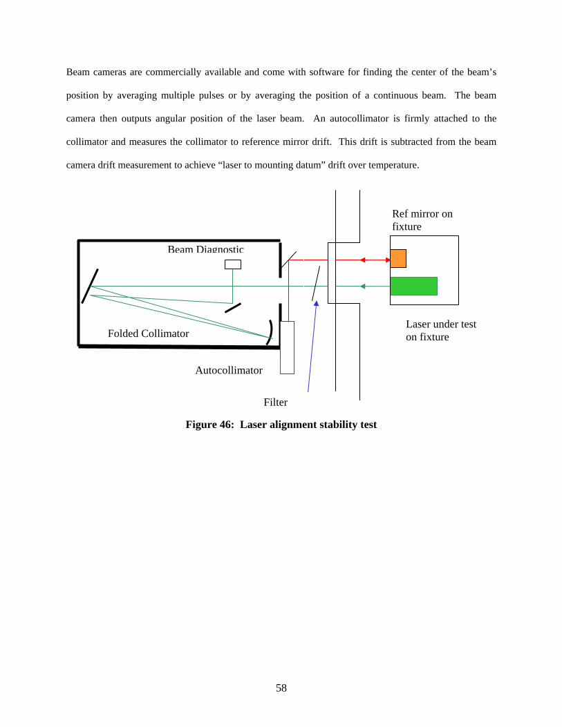
Beam cameras are commercially available and come with software for finding the center of the beam’s
position by averaging multiple pulses or by averaging the position of a continuous beam. The beam
camera then outputs angular position of the laser beam. An autocollimator is firmly attached to the
collimator and measures the collimator to reference mirror drift. This drift is subtracted from the beam
camera drift measurement to achieve “laser to mounting datum” drift over temperature.
Folded Collimator
Beam Diagnostic
Laser under test on fixture
Autocollimator
Filter
Ref mirror on fixture
Figure 46: Laser alignment stability test
58

CHAPTER V LASER ALIGNMENT AND RETENTION METHODS
Some configurations and use cases of electro-optical systems cannot passively meet alignment
stability needs without added enhancements. Laser systems are notorious for being sensitive to
temperature changes, and require additional correction techniques such as temperature calibration,
boresight modules, or active correction. Ideally, these methods would not be required if the root causes of
alignment instability were eliminated internal to the system. The system would only require initial
alignment using an accurately focused collimator target.
5.1 Temperature ca l ibrat ion
Temperature calibration can be performed on a whole electro optical system. This method uses
an equation to move an aiming reference or a steering mirror based upon inputs from temperature sensors
inside the system. The calibration process begins with measuring alignment drift of the system over
temperature and collecting temperature data using temperature sensors within the system. A correlation
of the temperature and alignment drift data is used to form a correction equation stored as a calibration
lookup table for use by software. The performance of this method is limited to the drift repeatability and
effort may be required to reduce sources of hysteresis. One drawback of this option is an added data
collection cycle for each unit that may only be valid for that set of matched components. If so, a new
calibration could be required with each component removal/repair.
5.2 Bores ight ing on the Vehic le
5 .2 .1 Bores ight Modules
Boresight modules are used to align a laser to sensor and are expected to keep excellent stability
over temperature. With robust structural and optical component design combined with the absence of
internal heat sources, boresight modules can achieve tight alignment stability performance. Typically
boresight modules are a separate “bolt-on” optical system with windows and can be designed with a
59

“monolithic” structure and optics for optimum stability. Some boresight modules are required to be
carried on the vehicle with the electro-optical system, so that when the temperature changes, a re-
alignment of the laser or aiming reference can be achieved. The boresight process involves the
positioning of the electro-optical system using its gimbals to look into the boresight module and fire the
laser or an internal source to check or re-align the optical axes. The end goal is ensure that the laser
points at the aiming device in the sensor’s field of view.
Figure 47: Collimator boresight module for a single input/output axis [Godfrey, 1980]
One type of boresight module uses a collimator design that functions, as described previously by
focusing a laser on a target made of a material that creates either an infrared or visible signature for
viewing by the sensor. Several different sizes and configurations can be tailored for the application. If
common optics are shared by the laser and visible sensor, a small collimator aperture is required as shown
in Figure 47. When two or more laser and sensor apertures exist, a collimator alone can be used for
alignment but the aperture must be big enough to encompass both laser and sensor apertures as shown in
Figure 48. By folding optical paths into a single axis with a beam splitter, a “mini-collimator” can be
used to reduce the volume of the module as shown in Figure 49 (Godfrey,1980). Boresight modules have
to be designed to combat condensate from forming on its optics. Another downside is the weight and
volume that the module adds to the vehicle. Alignment stability over temperature must be the key design
60

requirement in selecting components and structure for collimator modules, since the electro optical
system depends upon the module for alignment truth.
Figure 48: Collimator boresight module for two optical axes [Godfrey, 1980]
Figure 49: Mini-collimator boresight module using a dichroic beam splitter [Godfrey, 1980]
61

5.2 .2 Internal Methods
A more desirable method of boresighting involves designing components inside the electro-
optical system strictly for aligning the laser with the sensor. A corner cube is a well-known device that is
made with three 90-degree facets for returning a beam back along the same axis with no sensitivity to
small alignment changes of the corner cube. A couple of methods for using a corner cube or hollow retro-
reflector and a beam splitter are shown in Figure 50. The sensor is shown as an image plane with
focusing optics. The object space is the location of the scene, which is ultimately where the laser should
point. (Gibson, 2000 )
Figure 50: Internal Boresighting Techniques using a Corner Cube [Gibson, 2000]
If the sensor and laser do not share optics, a piece of a corner cube called a lateral transfer prism
can be used to accurately send the laser axis back into the sensor, provided the sensor has some sensitivity
at the wavelength of the laser. This can be hidden inside the base of a pod as shown in Figure 51, for use
over temperature as needed (Godfrey, 1980). Lateral transfer prisms are known for their stability over
62

temperature as they are made out of a single material. The corner cube is insensitive to small pointing
errors, making it “alignment insensitive” as the holding structure flexes or changes position over
temperature. (Yoder, 1993)
Figure 51: Boresighting method using a lateral transfer prism [Godfrey, 1980]
5.3 Act ive Correct ion
The most desired stability enhancement aside from “set it and forget it” is active correction,
where the laser is actively aligned either to the mechanical structure or ideally to the sensor. One method
used on the CALIPSO space LIDAR project involved steering the laser to peak the signal in the laser
receiver. For this application, the collection telescope was accurately positioned at an earth target using a
video camera. The laser receiver was accurately aligned and maintained through stable structural design
and the laser only needed active alignment (Seckar, 2005). This method has been applied in a similar
manner by having a laser imaging sensor or laser spot tracker that is dedicated to actively keep the laser
aligned, while another sensor views the scene or target. The laser-spot sensor can be used to steer the
63

laser or move the aiming reference. The dedicated laser-spot sensor must be kept aligned passively with
other “aiming” sensors, since only the laser’s stability is actively corrected.
Figure 52: Active Beam Alignment Compensation [Mitchell, 2001]
Another active laser alignment method combines fast steering mirrors and quadrature detectors to
simultaneously keep the laser beam centered and aligned while it is being fired at a target as shown in
Figure 52. The quadrature detectors are beam position feedback sensors used as truth references. If the
sensor’s optical axis or line of sight can be held stable over temperature, using methods previously
discussed, the thermal effects on the laser’s alignment can be compensated without any need for boresight
modules. The temperature sensitive mirror position feedback sensors can be used for inertial stabilization
around a center position command determined by the quadrature detectors.
64

CHAPTER V I CASE STUDY: USING PRINCIPLES OF AXIOMATIC DESIGN TO SOLVE AN
ALIGNMENT STABILITY PROBLEM
6.1 Axiomatic Des ign Background
The Axiomatic Design Process breaks the problem down into four separate domains as shown in
Figure 53. Each domain has its own set of elements, the mapping between domains can be described by a
set of matrices where:
[R] is the requirement matrix,
[D] is the design matrix, and
[C] is the component matrix.
Likewise:
{CN} is the customer needs vector,
{FR} is the functional requirements vector,
{DP} is the design parameter vector, and
{C} is the component vector.
The cornerstones of Axiomatic Design are the Independence Axiom and the Information Axiom.
The Independence Axiom stresses the independence of functional requirements. Independent
requirements can stand by themselves, do not conflict with other requirements, and are mapped to a single
design entity. The Information Axiom stresses design optimization that becomes the Design Parameters
(DP’s), providing a solution that completely implements the functional requirements with the minimum
set of components and interfaces. These principles apply directly when developing a new design.
Applying axiomatic design to an existing problem is slightly different in that it deals mostly in the area of
Functional Requirements and Design Parameters.
65
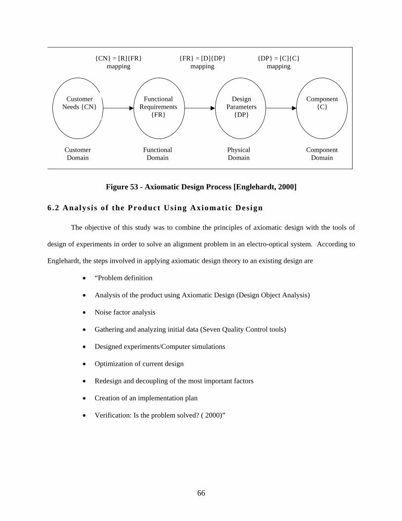
Customer Domain
{CN} = [R]{FR} mapping
Functional Domain
PhysicalDomain
Component Domain
Customer Needs {CN}
{FR} = [D]{DP}mapping
{DP} = [C]{C} mapping
Functional Requirements
{FR}
Design Parameters
{DP}
Component{C}
Figure 53 - Axiomatic Design Process [Englehardt, 2000]
6 .2 Analys is of the Product Using Axiomatic Des ign
The objective of this study was to combine the principles of axiomatic design with the tools of
design of experiments in order to solve an alignment problem in an electro-optical system. According to
Englehardt, the steps involved in applying axiomatic design theory to an existing design are
• “Problem definition
• Analysis of the product using Axiomatic Design (Design Object Analysis)
• Noise factor analysis
• Gathering and analyzing initial data (Seven Quality Control tools)
• Designed experiments/Computer simulations
• Optimization of current design
• Redesign and decoupling of the most important factors
• Creation of an implementation plan
• Verification: Is the problem solved? ( 2000)”
66
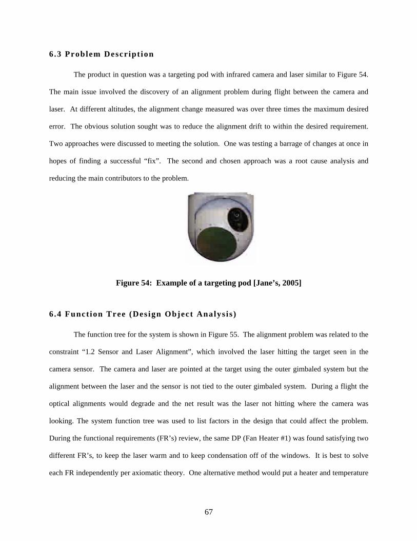
6.3 Problem Descr ipt ion
The product in question was a targeting pod with infrared camera and laser similar to Figure 54.
The main issue involved the discovery of an alignment problem during flight between the camera and
laser. At different altitudes, the alignment change measured was over three times the maximum desired
error. The obvious solution sought was to reduce the alignment drift to within the desired requirement.
Two approaches were discussed to meeting the solution. One was testing a barrage of changes at once in
hopes of finding a successful “fix”. The second and chosen approach was a root cause analysis and
reducing the main contributors to the problem.
Figure 54: Example of a targeting pod [Jane’s, 2005]
6.4 Funct ion Tree (Des ign Object Analys is )
The function tree for the system is shown in Figure 55. The alignment problem was related to the
constraint “1.2 Sensor and Laser Alignment”, which involved the laser hitting the target seen in the
camera sensor. The camera and laser are pointed at the target using the outer gimbaled system but the
alignment between the laser and the sensor is not tied to the outer gimbaled system. During a flight the
optical alignments would degrade and the net result was the laser not hitting where the camera was
looking. The system function tree was used to list factors in the design that could affect the problem.
During the functional requirements (FR’s) review, the same DP (Fan Heater #1) was found satisfying two
different FR’s, to keep the laser warm and to keep condensation off of the windows. It is best to solve
each FR independently per axiomatic theory. One alternative method would put a heater and temperature
67

sensor in the laser to solve the laser cold constraint. This decoupling was later considered as a test
configuration of the system for determining effects of not running the pod heater.
Figure 55: Partial Functional Analysis Tree
68

Collecting Telescope
Beam Expander Laser
Window
Infrared Window
Laser
Infrared Detector
Laser Steering Mirror
Image Steering Mirror
Focus Cell
Fan Heater
Intake Air Cooling Fan
Figure 56: Optical Schematic
6.4 .1 Descr ipt ion of the Major Components
A simplified optical path schematic is shown in Figure 56. The pod was designed to protect the
optical components from environmental factors and mounted in the outer gimbaled system for pointing.
Internal to the pod was an energy-collecting telescope, stabilizing mirror, and imaging optics mounted in
front of an infrared camera. Also included were a laser, steering mirror, and expanding optics. The pod
was designed with a software-controlled heater and fan (Fan Heater #1) to warm the inside of the pod to
keep condensation off of the windows and warm the camera to 10C (degrees Celsius) thereby keeping the
laser above its –10C optics design constraint. At some warm temperatures, the laser required forced
69
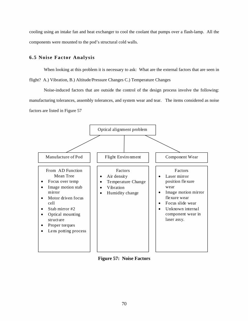
cooling using an intake fan and heat exchanger to cool the coolant that pumps over a flash-lamp. All the
components were mounted to the pod’s structural cold walls.
6.5 Noise Factor Analys is
When looking at this problem it is necessary to ask: What are the external factors that are seen in
flight? A.) Vibration, B.) Altitude/Pressure Changes C.) Temperature Changes
Noise-induced factors that are outside the control of the design process involve the following:
manufacturing tolerances, assembly tolerances, and system wear and tear. The items considered as noise
factors are listed in Figure 57
Manufacture of Pod Flight Environment Component Wear
From AD Function Mean Tree
• Focus over temp • Image motion stab
mirror • Motor driven focus
cell • Stab mirror #2 • Optical mounting
structure • Proper torques • Lens potting process
Factors • Air density • Temperature Change • Vibration • Humidity change
Factors • Laser mirror
position flexure wear
• Image motion mirror flexure wear
• Focus slide wear • Unknown internal
component wear in laser assy.
Optical alignment problem
Figure 57: Noise Factors
70

6.6 Gathering and Analyzing Ini t ia l Data
What are the driving factors for the gathering and analysis of data: Temperature, Pressure, or
Vibration? Qualification tests were previously run for alignment performance before and after vibration.
Image and laser-stabilizing mirror performance was also previously verified during vibration. There are
no known pressure-sensitive elements in the pod, and the pod itself relieves pressure through its seals.
Temperature effects are known to cause problems on optical systems, most generally through thermal
expansion of materials and associated thermal gradients.
The first step was to gather alignment data on the optical system over the temperature ranges seen
in flight, thus bounding the magnitude of the problem. The goal was to establish a baseline of variations
for the temperature ranges. The necessary test equipment was set up to accurately measure the alignment
variation over the temperature ranges.
An anticipated cause-effect diagram was developed from the factors in the function tree as shown
in Figure 58. The alignment problem was measured to be 4 times the desired requirement on a sample of
two systems, which was close to the magnitude of that seen in flight tests.
Figure 58: Cause and Effect Possibilities
71
6.7 Stat i s t ica l Experimental Des ign
The goal for this step was twofold; to determine the root cause of the problem and to implement
design solutions that provide the lowest cost of retrofitting the existing systems. When implementing
statistical experimental design, both cost and schedule can be controlled. Two methods were initially
considered for experimental design: 1.) Up-and-down, 2.) Taguchi. The Up-and-down method obtains
data from sensitivity experiments. Only one observation per sample is made before the sample is
discarded. The Taguchi method allows for the measurement of a number of different parameters and their
interactions, rather than only varying one variable at a time and continually repeating the experiments for
all variables.
6.7 .1 Ini t ia l Decis ions
To minimize the number of experiments, it is best to limit the number of variables required to
test. The decision was made to consider the suspected players and then rank them in relation to overall
problem based on initial component data. Knowing their interactions in the system will require
experimentation.
A structural model with optical alignment sensitivity coefficients already existed for each optical
component or assembly. This model predicted drifts of 16% desired goal; given isothermal temperature
changes of 50C (no gradients). The structural model predicted motion of optical components based on
thermal expansion. It is known that the camera is heated to 10C using the heater fan and the pod skin
temperature can get to -20C in flight. A rough gradient was blended into the thermal model and it
predicted an alignment drift very near the goal, which did not explain the main contributor. This model
could not accurately depict all gradients that do form under normal operation.
What are the sources that would cause gradients to form? The candidates are heating fan, cooling
fan, electronic components, infrared cooler and ambient air temperature. A thermal survey was
recommended to determine if alignment drift could be correlated with gradient development or
temperature changes. Through the axiomatic design analysis, it was recommended to decouple the pod
72

air heater from trying to meet two requirements of combating window condensate and keeping the laser
warm. One experiment considered was a software change and an additional temperature feedback sensor
to make use of existing heaters in the laser. This would allow the laser to fire at cold ambient
temperatures without having to run the pod air heater.
The next question asked was what components move within the optical system, and do they move
as designed. Both the focus cell and steering mirrors were designed to move, and were the subject of the
next step in the investigation for drift contributors. The focus cell must move approximately .050 inches
to account for focal length changes due to expansion of the metal housing and change in index of
refraction of the glass optics. The focus cell optics must travel along the optical axis or an alignment shift
occurs. A tolerance analysis demonstrated that if assembled correctly by clocking to the machined
surfaces, the focus cell would not cause more than 16% of the total allowable alignment drift over the
temperature range in question. Vendor test data of a sample of steering mirror position sensors showed a
variability of drift over temperature changes in excess of 3 times the alignment stability goal. The effects
of the steering mirrors in the system were later tested as a part of a designed experiment where one
“level” or configuration is with the mirror installed. Another “level” later tested was with a surrogate
“rigid/fixed” mirror made of diamond-turned aluminum that mounted in the same location as the steering
mirror. The final known contributor investigated was drift internal to the laser assembly. It was already
known from the laser vendor’s qualification tests that the laser has an internal drift of 40% of the overall
allowable sensor to laser alignment.
By ranking each suspect drift contributor, as shown in Figure 59, it is easy to see what problems
needed to be studied first. Using the baseline drift measurement of 4 times the goal, there should be two
main determinates to characterize using the design of experiments: gradients and steering mirrors.
73

0 50 100 150 200 250 300 350 400 450
Problem
Steering Mirrors
Heating/coolinggradients
Laser Internal Drift(spec)
Focus cell (sample ofthree)
Thermal Model (nogradients)
Initi
al C
ontr
ibut
or E
stim
ates
and
Mea
sure
men
ts
Alignment Problem in Percent of Goal
Figure 59: Initial Estimates of Probable Contributors to the Problem
6.7 .2 Experimental Setup
In looking at Figure 59, the following three “factors” were chosen to vary through tests in the
system: two steering mirrors and the pod heater control. Each steering mirror was tested with or without
its “fixed” or rigid surrogate. The pod heater was allowed to operate during some tests and during others
it was turned off. In order to still have cold temperature laser firing, a new laser heater would run keeping
the laser above –5C in the absence of the pod heater. These three factors make up the basis for an “L8”
two-level Taguchi factorial set of tests. Two level means each variable is either high or low (on or off), as
shown in the setup of tests in Table 2. For example, Row #1 has a “1” for all three variables. This means
that all three variables are at the baseline configuration. For this run, both steering mirrors were installed
and the window heater was operating with a 10C camera temperature set point.
74

All eight runs (row #’s) were performed on one sample system. The alignment angle between the
laser and camera was measured over temperature. The goal is that the alignment drift stay within a
specified angle at all times. Each run was repeated over the exact same environmental and time
conditions and the system was allowed to run for two hours at each of seven temperature steps before
taking an alignment measurement. The result (Yi) of each run was the maximum difference between any
two of the seven data points divided by goal. These eight runs could have been repeated on one or two
more systems and a Y-bar or average observance for each row would be used for further analysis.
Table 2: L8 Array and descriptions
Factor A B C
Observed Maximum
Drift Delta /goal
Row #
Heater 10C Air
or -5C Laser
Image Mirror -
Steering or Fixed
Laser Mirror -
Steering or Fixed Yi Y bar
1 1 1 1 4.16 4.16
2 1 1 2 3.1 3.1
3 1 2 1 3.5 3.5
4 1 2 2 2.5 2.5
5 2 1 1 2.3 2.3
6 2 1 2 1.67 1.67
7 2 2 1 2.4 2.4
8 2 2 2 0.83 0.83
6 .7 .3 Analys is of Variance (ANOVA)
ANOVA is the standard way of statistically comparing the data collected using the Taguchi method. It
enables the observer to make decisions about a set of observed parameters. Since the above experiment
involved 3 factors, a 3-way ANOVA can be performed.
75

6.7.3.1 Calculations The ANOVA calculations were performed in a spreadsheet. The first step involves calculating the Main
Effect Factor for all eight columns of the L8 matrix.
4∑∑ −
=levellowatYlevelhighatY
MEF iif
The degree of freedom is the number of levels minus one for each column except error. The error degree
of freedom is “1” for this L8 matrix. Next is the sum of squares total calculation:
82 ∑∑ += i
iT
YYSS where “8” is the number of runs.
Next is the calculation of sum of squares:
2)(2 fi MEFSS = and sum of squares error ∑−= iTE SSSSSS
Next is the calculation of mean squares: iii dfSSMS /= .
The F-test is performed by the following equation: Eii MSMSF /= .
Finally, the percent contribution for each factor or combination of factors is calculated:
T
Eii SS
MSMSPC )(100 −= and PCError is simply ∑−= iE PCPC 100 .
6.7.3.2 ANOVA Results The ANOVA, in Table 3, shows the results of the statistical calculations. Surprisingly, the pod heater has
the largest percent contribution. This was flagged as a potential issue during the axiomatic design object
analysis. The steering mirrors also have a contribution and need to be improved. This experimental
design led to meaningful data and a guideline for improving the design. The next steps would involve
incorporating and validating design improvements.
76

Table 3: ANOVA Results Maximum Drift Delta / goal
Source SS df MS F
%
Contribution
Heater 10C Air or -5C Laser 4.5905 1 4.5905 36.724 60.27%
Image Mirror -Steering or Fixed 0.5000 1 0.5000 4.000 6.56%
Laser Mirror -Steering or Fixed 2.2685 1 2.2685 18.148 29.78%
AB 0.0338 1 0.0338 0.270 0.44%
AC 0.0024 1 0.0024 0.020 0.03%
BC 0.0968 1 0.0968 0.774 1.27%
Error 0.125 1 0.125 1.64%
Total 7.617 7
6.8 Opt imizat ion, Redes ign, and Decoupl ing
The results of the design of experiments (DOE), component testing, and modeling, showed what
needed to be improved or optimized. Upon further investigation, the heater fan caused large gradients on
the telescope. The pod heater was originally designed to keep the laser warm and defog the windows.
The use of the laser heater alone proved to yield better alignment results. Early analysis of the FR/DP
matrix pointed out a concern where the fan heater design parameter was trying to satisfy two different
functional requirements. The optimized design keeps the laser above –10C with an existing built-in laser
heater and new temperature sensor. Since the pod heater cannot be used without alignment impacts, a
desiccant material was installed to satisfy the functional requirement of eliminating condensation on the
optics. The test results determined this system modification provided a solution to minimize the drift to
within the specification, when fixed surrogate mirrors were installed in place of the steering units. The
de-coupling of the same design parameter that affected two functional requirements was key and was a
predicted issue in the functional tree.
77
The steering mirrors were shown to be the second largest contributor to alignment stability during
the design of experiments. The mirrors were later studied more efficiently outside the system on a test
stand using a reference mirror for measuring relative drift of the mirror over temperature. Additional
development resulted in a self-calibrating algorithm to minimize the mirror drift.
6.9 Creat ion of an Implementat ion Plan
An integrated implementation plan should include a timeline and anticipated costs to make a
design change. First an engineering change proposal is issued. Once accepted, the drawings that need to
be changed are modified, the software lifecycle requirements are determined and modifications are
applied, tested, integrated, released, and qualified. Manufacturing and modification processes need to be
modified to allow for the new engineering changes. When determining and building the implementation
plan, areas to consider include how many units can be repaired, within a timeframe without impacting
normal production schedule.
6.10 Veri f icat ion: Is the Problem Solved?
After the changes described are implemented, a sample of systems should be measured over
temperature to verify that the design changes definitely fixed the problem. The systems should also be
flight tested to demonstrate success.
6.11 Case Study Conclus ion
Applying the axiomatic design process to an existing problem can provide for a solution that may
not be obvious when using a more traditional approach to solving a problem similar to this one in
complexity. This particular problem was composed of many design components that must work together
to provide the expected product results. Understanding and defining the relationship between the design
components was critical in the axiomatic design process and laying the groundwork for experimental
design. Narrowing down the number of variables to a meaningful set for testing saves time and money.
The Taguchi method allows for testing a combination of variables. Finally, using Analysis of Variance
78

yields knowledge of what factors contribute to the problem. Design of experiments is a valuable tool to
the engineer for solving problems and making design decisions. The principles and tools of axiomatic
design methodology are not only available for new design process but can also be used to solve an
existing problem through the mapping out functional requirements, design parameters, and design
constraints.
79

CHAPTER VII SUMMARY AND CONCLUSIONS
Electro optical systems for military and scientific applications will be exposed to environmental
temperature changes. Various optical paths must stay aligned within customer requirements. Alignment
stability can be designed into a system through proven techniques but must ultimately be tested for
performance. Some laser systems with strict retention requirements require additional stability
improvements due to issues inherent to the particular design.
During the design phase, alignment stability must be in the forefront of each decision including
optical layout, material selections, structural design, optics mounting schemes, and thermal management.
Trade-offs made during each of these stages can impact the alignment stability of two or more sensors or
between a sensor and a laser. Several “tricks” in the optical layout can improve alignment performance.
These include common optics and alignment “insensitive” components. Robust structural design for
alignment retention includes material selection and fabrication processes that emphasize low residual
stress. Thermal management must include isolating the optical bench from heat sources and minimizing
any thermal gradients. Lens, beam splitter, and mirror mounts must also be tested to meet stability
requirements before being incorporated into the design. Low stress mounts at room temperature may not
necessarily be the best performers over operational temperatures.
In testing systems and components for alignment retention over temperature, several pieces of
equipment are essential to accurately learn stability performance. The collimator allows accurate testing
of the alignment of multiple sensors and lasers provided the targets are accurately placed at the focal
point. The autocollimator is a powerful device for measuring small angles. Stability measurements are
more accurate if two components are measured relative to each other by a single autocollimator. When
combined with a special temperature chamber with an optical window, these pieces of test equipment
give the final proof of the electro optical system design.
80

The alignment drift of laser systems is a well-known issue. If the drift performance is not
achieved with beam expansion and thermal management, other methods are required to ensure alignment.
These methods include temperature calibration, operational boresighting techniques, and active
correction. When periodic boresighting is required, components internal to the electro optical system are
more desired over an external boresight module. Finally, active correction is the most desired method for
maintaining laser drift whether it involves quadrature detectors for monitoring the output beam or a
dedicated sensor for seeing the laser spot on the target.
If the alignment stability of an existing design needs improved, an axiomatic design analysis
combined with designed experiments can lead to finding drift players and improving the system
performance. The existing design analysis, per axiomatic theory, requires mapping out the functional
requirements, design parameters, and constraints for finding potential origins of the problem.
Experimental design using the Taguchi method, combines tests to save time and money, and it yields the
results of component interactions.
Alignment stability is a core requirement of sensors and lasers in many different electro optical
systems. The impacts of misalignments on a space-based sensor can result in the inability to study a
distant star’s chemical composition and the waist of an expensive mission. For military targeting
systems, laser alignment to the aiming reference is critical for the placement of laser-guided weapons. As
the need for surgical strike continues to grow, optical alignment stability of electro optical systems over
their environmental temperatures will continue to be a challenging design requirement.
81

REFERENCES
Dickey, F.M., J.R. White, R.H. Allen, R.L.Sledge. 1980. “A common collimator approach to alignment and performance testing of laser ranger/designators and thermal imaging systems”, Proceedings of SPIE Vol. 251, Optical Alignment. Engelhardt. 2000. “Improving Products And Systems By Combining Axiomatic Design, Quality Control-Tools And Designed Experiments,” Proceedings of ICAD 2000 Feng, Chen, Anees Ahmad, and Farzin Amzajerdian. 1995. “Design and analysis of a spaceborne lidar telescope”, SPIE Vol 2540. Gibson, Allan. 2000. “Laser pointing technology”, SPIE Proceedings Giesen, Peter and Erik Folgering. 2003. “Design guidelines for thermal stability in opto-mechanical instruments”, Optomechanics, SPIE Proceedings Glenn Boreman. 1998. Basic Electro Optics for Electrical Engineers. SPIE Press. Godfrey, Thomas E., and Walter M. Clark. 1980. “Boresighting of airborne laser designator systems.” Proceedings of SPIE Vol. 251, Optical Alignment Henson, Tammy, Les Krumel, and Dick Blake. 1999. “Multispectral Thermal Imager Optical Assembly Performance and Integration of the Flight Focal Plane Assembly”, SPIE Conference, Imaging Spectrometry V Hane, Kazuhiro and Minoru Sasaki. 2003. “Optical Sensors and Their Applications” Opto-Mechatronic SystemsHandbook: Techniques and Applications, Boca Raton: CRC Press LLC Hofferbert, R., D. Lemke, U. Grozinger, T. Henning, S. Mertin, R.R. Rohloff, K. Wagner, G.S. Wright, H. Visser, J. Katzer, M. Salvasohn, W. Posselt, G. Fargant, and R. Nalbandian. 2003. “Cryomechanisms for the instruments MIRI and NIRSpec on the James Webb Space Telescope (JWST),” Proceedings of SPIE, Vol 5152, Infrared Spaceborne Remote Sensing XI. Hylan, Jason, Leroy M. Sparr, Raymond G. Ohl, J. Eric Mentzell, Matthey A. Greenhouse, John W. MacKenty. 2003. “Lessons learned from the design, fabrication, integration, and test of a cryogenic, IR spectrometer for ground-based astronomy”, Crogenic Optical Systems and Instruments X, SPIE Proceedings. Jane’s Online. 2005. Airborne Systems-Observation and Surveillance-Turret Sensors -United States-Electro-Optic Systems. Janes Information Group, http://www2.janes.com Kvamme, E. Todd, Dario Trevias, RaShelle Simonson, Larry Sokolsky. 2005. “A low stress cryogenic mount for space-borne lithium fluoride optics,” Optomechanics, SPIE Proceedings Lee, Noenke van der, Pieter Kappelhof, Roger Hamelinck. 2003. “Flexure-based alignment mechanisms: design, development and application,” Optomechanics, SPIE Proceedings. Leviton, Douglas B. 2003. “Ultra-high resolution, absolute, Cartesian electronic autocollimator”, Proceedings of SPIE Vol 5190, Recent Developments in Traceable Dimensional Measurements II.
82

Mainzer, Amanda K., Erick T. Young, Lynn W. Huff, and Daniel S. Swanson. 1998. Pre-launch performance testing of the Pointing Calibration & Reference Sensor for SIRTF”, SPIE Conference on Space Telescopes and Instruments. Mitchell, Phillip V., Peter B. Griffith, and Donald K. Henderson. 2001. “Fast-steering mirrors improve active beam stabilization”, Optroelectronics World October O’Brien, T.P., and B. Atwood. 2003. “Athermalization of a Schmidt Camera,” Instrument Design and Performance for Optical/Infrared Ground-based Telescopes, SPIE Proceedings. Ohl, Raymond G., M.P. Barthelmy, S.W. Zewari, R.W. Toland, J.C. McMann, D.F.Puckett, J.G. Hagopian, J.E. Hylan, J.E Mentzell, R.G. Mink, L.M. Sparr, M.A. Greenhouse, and J.W. MacKenty. 2002. “Comparison of stress relief procedures for cryogenic aluminum mirrors”, Cryogenic Optical Systems and Instruments IX, SPIE Proceedings. Paquin, R.A. 1999. “Metal Mirrors”, Optomechanical Engineering Handbook, Boca Raton: CRC Press LLC PLX Inc. 2005. “Optical Alignment Made Simple”, an online white paper. Ridgway, Stephen T., “Thermal Control and Optical Tolerance,” a white paper found at http://www.chara.gsu.edu/CHARA/Reports/appendixt.pdf Seckar, Chris, Larry Guy, Angela DiFronzo, and Carl Weimer. 2005. “Performance Testing of an Active Boresight Mechanism for Use in the CALIPSO Space Bourne LIDAR Mission,“ Optomechanics, SPIE Proceedings Smith, Warren J. 1990. Modern Optical Engineering The Design of Optical Systems, 2nd Edition, New York: McGraw Hill Inc. Veggel, Marielle van, Arno Wielders, Hedser van Brug, Nick Rosielle, Henk Nijmeijer. 2005. “Expermental set-up for testing alignment and measurement stability of a metrology system in silicon carbide for GAIA”, SPIE Proceedings, Optomechanics Vukobratovich, Daniel and Suzanne Vukobratovich. 1993. Introduction to Opto-mechanical Design Vukobratovich, Daniel. 1999. “Optomechanical Design Principles”, Optomechanical Engineering Handbook, Boca Raton: CRC Press LLC Wilson, Debbie and Kathryn D. Li Dessau. 2005. “Optimizing the Performance of Optical Mounting Systems”, Optics & Photonics News, March Yoder, Jr,, P.R. 1993. Opto-Mechanical Systems Design, New York, NY: Marcel Dekker, Inc. ---1999. “Optical Mounts: Lenses, Windows, Small Mirrors, and Prisms”, Optomechanical Engineering Handbook, Boca Raton: CRC Press LLC Zona, James P., and Chris L. Willis. 2001. “Testing Boresight Stability of Optomechanical Subassemblies”, Optomechanical Design and Engineering, SPIE Proceedings
83