Embed Size (px)
Citation preview
IG_E
F-N
100
0-T
_R1
A
EBTRON, Inc. 1663 Hwy. 701 S., Loris SC 29569 • Toll Free: 800.2EBTRON (232.8766) • Fax: 843.756.1838 • Internet: EBTRON.com
Installation Guide
EF-N1000 SeriesBACnet/Modbus Network Output
Electronic Low Flow (ELF)Airflow/Temperature Measurement Station
Document: IG_EF-N1000-T_R1A
a measurable difference!EBTRON ®
Thermal Dispersion Airflow Measurement Technology
EF-N1000-T ELFQuick Installation Guide
EB-Flow Electronic Low Flow ELF BACnet/Modbus Output Airflow Station
Part Number: 930-0185
IG_E
F-N
100
0-T
_R1
A
a measurable difference!
®
EB-FLOW EF-N1000 ELFINSTALLATION GUIDE - ELECTRONIC LOW FLOW ‘ELF’ BACNET/MODBUS OUTPUT
EBTRON, Inc. 1663 Hwy. 701 S., Loris SC 29569 • Toll Free: 800.2EBTRON (232.8766) • Fax: 843.756.1838 • Internet: EBTRON.com2
IG_E
LF-D
_R1
E
1. INTRODUCTION AND SCOPE . . . . . . . . . . . . . . . . . . . . . . . . . . . . . . . . . . . . . . . . . . . . . . . . . . . . . . . . . . . . . . . . . . . . . . . . . . . . .3
2. EF-N1000 INSTALLATION . . . . . . . . . . . . . . . . . . . . . . . . . . . . . . . . . . . . . . . . . . . . . . . . . . . . . . . . . . . . . . . . . . . . . . . . . . . . . . .3
3. ELF PREPARATION FOR USE . . . . . . . . . . . . . . . . . . . . . . . . . . . . . . . . . . . . . . . . . . . . . . . . . . . . . . . . . . . . . . . . . . . . . . . . . . . . .5
4. ELF INTERCONNECTIONS . . . . . . . . . . . . . . . . . . . . . . . . . . . . . . . . . . . . . . . . . . . . . . . . . . . . . . . . . . . . . . . . . . . . . . . . . . . . . . .54.1 ELF 24 VAC Power Connections . . . . . . . . . . . . . . . . . . . . . . . . . . . . . . . . . . . . . . . . . . . . . . . . . . . . . . . . . . . . . . . . . . . . .64.2 S1 - ELF Configuration DIP Switch Settings . . . . . . . . . . . . . . . . . . . . . . . . . . . . . . . . . . . . . . . . . . . . . . . . . . . . . . . . . . .64.3 Setting the MAC Address . . . . . . . . . . . . . . . . . . . . . . . . . . . . . . . . . . . . . . . . . . . . . . . . . . . . . . . . . . . . . . . . . . . . . . . . . .64.4 Setting the Baud Rate . . . . . . . . . . . . . . . . . . . . . . . . . . . . . . . . . . . . . . . . . . . . . . . . . . . . . . . . . . . . . . . . . . . . . . . . . . . . .94.5 J4 - ELF RS-485 Network Termination Selection . . . . . . . . . . . . . . . . . . . . . . . . . . . . . . . . . . . . . . . . . . . . . . . . . . . . . . .94.6 Restoring Factory Default Settings . . . . . . . . . . . . . . . . . . . . . . . . . . . . . . . . . . . . . . . . . . . . . . . . . . . . . . . . . . . . . . . . . .9
5. ELF BACnet CONFIGURATION . . . . . . . . . . . . . . . . . . . . . . . . . . . . . . . . . . . . . . . . . . . . . . . . . . . . . . . . . . . . . . . . . . . . . . . . . . .105.1 Changing BACnet Device Object Instance Number . . . . . . . . . . . . . . . . . . . . . . . . . . . . . . . . . . . . . . . . . . . . . . . . . . . .10
5.1.1 Matching BACnet Device Object Instance Number to MAC Address . . . . . . . . . . . . . . . . . . . . . . . . . . . . . . . . .105.1.2 Setting BACnet Device Object Instance Number to a value different than MAC Address . . . . . . . . . . . . . . . .10
6. ELF MODBUS CONFIGURATION . . . . . . . . . . . . . . . . . . . . . . . . . . . . . . . . . . . . . . . . . . . . . . . . . . . . . . . . . . . . . . . . . . . . . . . . .10
7. ELF INITIAL START UP / NORMAL OPERATION . . . . . . . . . . . . . . . . . . . . . . . . . . . . . . . . . . . . . . . . . . . . . . . . . . . . . . . . . . . . . .11
8. FOR ADDITIONAL INFORMATION . . . . . . . . . . . . . . . . . . . . . . . . . . . . . . . . . . . . . . . . . . . . . . . . . . . . . . . . . . . . . . . . . . . . . . . .11
APPENDIX A - ELF BACnet Object Properties . . . . . . . . . . . . . . . . . . . . . . . . . . . . . . . . . . . . . . . . . . . . . . . . . . . . . . . . . . . . . . . . .12
APPENDIX B - ELF Modbus Register Map . . . . . . . . . . . . . . . . . . . . . . . . . . . . . . . . . . . . . . . . . . . . . . . . . . . . . . . . . . . . . . . . . . .12
Table of Contents
Figure 1. ELF Installation Applications and Orientation . . . . . . . . . . . . . . . . . . . . . . . . . . . . . . . . . . . . . . . . . . . . . . . . . . . . . . . . .4
Figure 2. ELF Installation Dimensions . . . . . . . . . . . . . . . . . . . . . . . . . . . . . . . . . . . . . . . . . . . . . . . . . . . . . . . . . . . . . . . . . . . . . . .5
Figure 3. ELF Circuit Board, Wiring and Configuration Switch Details . . . . . . . . . . . . . . . . . . . . . . . . . . . . . . . . . . . . . . . . . . . . . .7
Figure 4. ELF Power and Signal Wiring Interconnections . . . . . . . . . . . . . . . . . . . . . . . . . . . . . . . . . . . . . . . . . . . . . . . . . . . . . . . .8
Figure 5. ELF Baud Rate Selection . . . . . . . . . . . . . . . . . . . . . . . . . . . . . . . . . . . . . . . . . . . . . . . . . . . . . . . . . . . . . . . . . . . . . . . . . .9
List of TablesTable 1. CONFIG Switch Settings . . . . . . . . . . . . . . . . . . . . . . . . . . . . . . . . . . . . . . . . . . . . . . . . . . . . . . . . . . . . . . . . . . . . . . . . . . .6
List of Figures
Copyright © EBTRON®, Inc.All brand names, trademarks and registered trademarks are the property of their respective owners. Information contained within this document is subject to
change without notice. Visit EBTRON.com to view and/or download the most recent versions of this and other documents.
All rights reserved.
LIST OF EFFECTIVE AND CHANGED PAGES
Insert latest changed pages (in bold text); remove and dispose of superseded pages.Total number of pages in this manual is 8.
Page No Revision * Description of Change Date1 through 12 . . . . . . . . . . .R1A . . . . . . . . . . . . .Initial document release. . . . . . . . . . . . . . . . . . . . . . . . . . . . . . . . . . . . . . . . . . . . . . . . . . . . .1/25/2016
* R1A indicates an original page without change
IG_E
F-N
100
0-T
_R1
A
a measurable difference!
®
EB-FLOW EF-N1000 ELFINSTALLATION GUIDE - ELECTRONIC LOW FLOW ‘ELF’ BACNET/MODBUS OUTPUT
EBTRON, Inc. 1663 Hwy. 701 S., Loris SC 29569 • Toll Free: 800.2EBTRON (232.8766) • Fax: 843.756.1838 • Internet: EBTRON.com 3
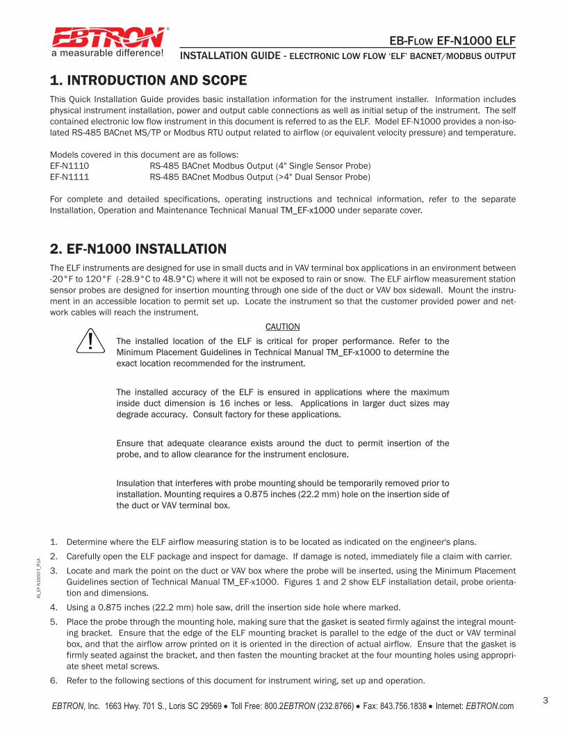
1. INTRODUCTION AND SCOPEThis Quick Installation Guide provides basic installation information for the instrument installer. Information includesphysical instrument installation, power and output cable connections as well as initial setup of the instrument. The selfcontained electronic low flow instrument in this document is referred to as the ELF. Model EF-N1000 provides a non-iso-lated RS-485 BACnet MS/TP or Modbus RTU output related to airflow (or equivalent velocity pressure) and temperature.
Models covered in this document are as follows:EF-N1110 RS-485 BACnet Modbus Output (4" Single Sensor Probe)EF-N1111 RS-485 BACnet Modbus Output (>4" Dual Sensor Probe)
For complete and detailed specifications, operating instructions and technical information, refer to the separateInstallation, Operation and Maintenance Technical Manual TM_EF-x1000 under separate cover.
2. EF-N1000 INSTALLATIONThe ELF instruments are designed for use in small ducts and in VAV terminal box applications in an environment between-20°F to 120°F (-28.9°C to 48.9°C) where it will not be exposed to rain or snow. The ELF airflow measurement stationsensor probes are designed for insertion mounting through one side of the duct or VAV box sidewall. Mount the instru-ment in an accessible location to permit set up. Locate the instrument so that the customer provided power and net-work cables will reach the instrument.
CAUTION
The installed location of the ELF is critical for proper performance. Refer to theMinimum Placement Guidelines in Technical Manual TM_EF-x1000 to determine theexact location recommended for the instrument.
The installed accuracy of the ELF is ensured in applications where the maximuminside duct dimension is 16 inches or less. Applications in larger duct sizes maydegrade accuracy. Consult factory for these applications.
Ensure that adequate clearance exists around the duct to permit insertion of theprobe, and to allow clearance for the instrument enclosure.
Insulation that interferes with probe mounting should be temporarily removed prior toinstallation. Mounting requires a 0.875 inches (22.2 mm) hole on the insertion side ofthe duct or VAV terminal box.
1. Determine where the ELF airflow measuring station is to be located as indicated on the engineer's plans.
2. Carefully open the ELF package and inspect for damage. If damage is noted, immediately file a claim with carrier.
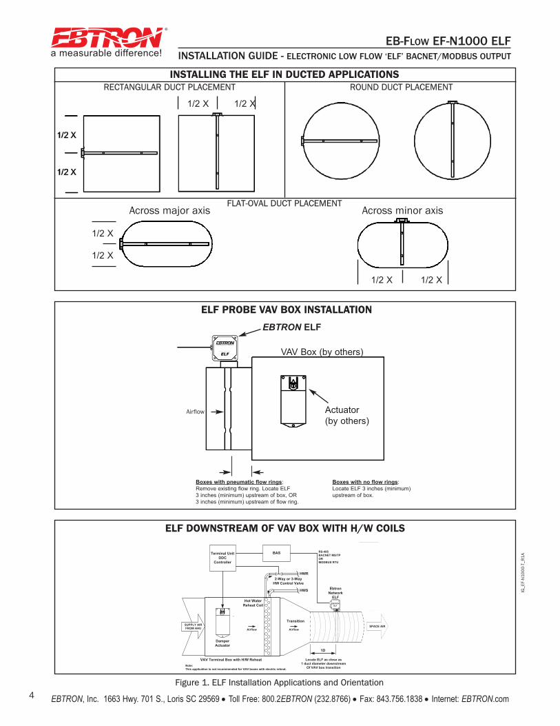
3. Locate and mark the point on the duct or VAV box where the probe will be inserted, using the Minimum PlacementGuidelines section of Technical Manual TM_EF-x1000. Figures 1 and 2 show ELF installation detail, probe orienta-tion and dimensions.
4. Using a 0.875 inches (22.2 mm) hole saw, drill the insertion side hole where marked.
5. Place the probe through the mounting hole, making sure that the gasket is seated firmly against the integral mount-ing bracket. Ensure that the edge of the ELF mounting bracket is parallel to the edge of the duct or VAV terminalbox, and that the airflow arrow printed on it is oriented in the direction of actual airflow. Ensure that the gasket isfirmly seated against the bracket, and then fasten the mounting bracket at the four mounting holes using appropri-ate sheet metal screws.
6. Refer to the following sections of this document for instrument wiring, set up and operation.
IG_E
F-N
100
0-T
_R1
A
a measurable difference!
®
EB-FLOW EF-N1000 ELFINSTALLATION GUIDE - ELECTRONIC LOW FLOW ‘ELF’ BACNET/MODBUS OUTPUT
EBTRON, Inc. 1663 Hwy. 701 S., Loris SC 29569 • Toll Free: 800.2EBTRON (232.8766) • Fax: 843.756.1838 • Internet: EBTRON.com4Figure 1. ELF Installation Applications and Orientation
INSTALLING THE ELF IN DUCTED APPLICATIONSROUND DUCT PLACEMENT
Across major axis Across minor axis
1/2 X 1/2 X
RECTANGULAR DUCT PLACEMENT
1/2 X 1/2 X
1/2 X
1/2 X
FLAT-OVAL DUCT PLACEMENT
Boxes with pneumatic flow rings:
Remove existing flow ring. Locate ELF
3 inches (minimum) upstream of box, OR
3 inches (minimum) upstream of flow ring.
Boxes with no flow rings:
Locate ELF 3 inches (minimum)
upstream of box.
EBTRON ELF
Actuator
(by others)
VAV Box (by others)
ELF PROBE VAV BOX INSTALLATION
Airflow
ELF DOWNSTREAM OF VAV BOX WITH H/W COILS
Airflow Airflow
VAV Terminal Box with H/W Reheat
EBTRONELF
Damper Actuator
Note:This application is not recommended for VAV boxes with electric reheat.
Locate ELF as close as 1 duct diameter downstream
Of VAV box transition
Hot Water Reheat Coil
Transition
1D
SUPPLY AIR FROM AHU SPACE AIR
Terminal Unit DDC
Controller
HWR
HWS
2-Way or 3-Way HW Control Valve
TFL
OND
BAS24VAC 24 VAC PWR INGND GROUND*
NET - RS-485 -GND GROUND*
NET + RS-485 +
Ebtron Network
ELF
RS-485BACNET MS/TPORMODBUS RTU
IG_E
F-N
100
0-T
_R1
A
a measurable difference!
®
EB-FLOW EF-N1000 ELFINSTALLATION GUIDE - ELECTRONIC LOW FLOW ‘ELF’ BACNET/MODBUS OUTPUT
EBTRON, Inc. 1663 Hwy. 701 S., Loris SC 29569 • Toll Free: 800.2EBTRON (232.8766) • Fax: 843.756.1838 • Internet: EBTRON.com 5
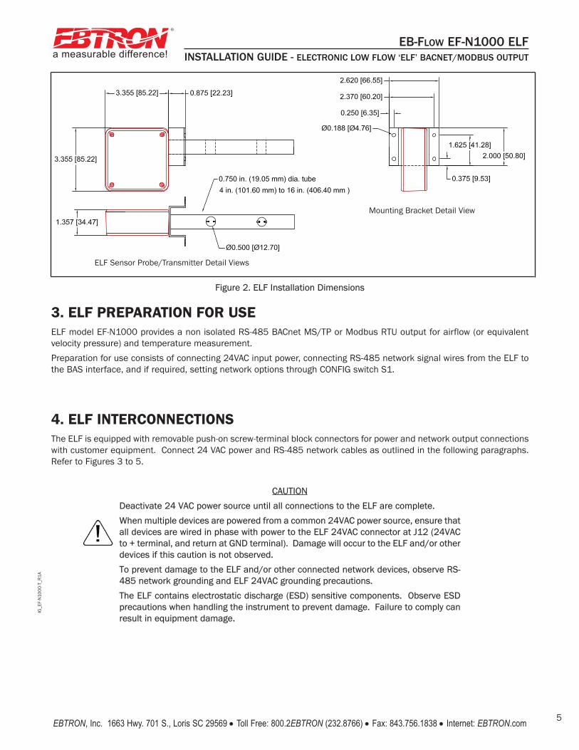
Figure 2. ELF Installation Dimensions
3. ELF PREPARATION FOR USEELF model EF-N1000 provides a non isolated RS-485 BACnet MS/TP or Modbus RTU output for airflow (or equivalentvelocity pressure) and temperature measurement.
Preparation for use consists of connecting 24VAC input power, connecting RS-485 network signal wires from the ELF tothe BAS interface, and if required, setting network options through CONFIG switch S1.
4. ELF INTERCONNECTIONSThe ELF is equipped with removable push-on screw-terminal block connectors for power and network output connectionswith customer equipment. Connect 24 VAC power and RS-485 network cables as outlined in the following paragraphs.Refer to Figures 3 to 5.
CAUTION
Deactivate 24 VAC power source until all connections to the ELF are complete.
When multiple devices are powered from a common 24VAC power source, ensure thatall devices are wired in phase with power to the ELF 24VAC connector at J12 (24VACto + terminal, and return at GND terminal). Damage will occur to the ELF and/or otherdevices if this caution is not observed.
To prevent damage to the ELF and/or other connected network devices, observe RS-485 network grounding and ELF 24VAC grounding precautions.
The ELF contains electrostatic discharge (ESD) sensitive components. Observe ESDprecautions when handling the instrument to prevent damage. Failure to comply canresult in equipment damage.
Mounting Bracket Detail View
ELF Sensor Probe/Transmitter Detail Views

IG_E
F-N
100
0-T
_R1
A
a measurable difference!
®
EB-FLOW EF-N1000 ELFINSTALLATION GUIDE - ELECTRONIC LOW FLOW ‘ELF’ BACNET/MODBUS OUTPUT
EBTRON, Inc. 1663 Hwy. 701 S., Loris SC 29569 • Toll Free: 800.2EBTRON (232.8766) • Fax: 843.756.1838 • Internet: EBTRON.com6
4.1 ELF 24 VAC Power ConnectionsThe ELF requires a power source capable of providing 22.8 to 26.4 VAC at 5 VA.
NOTE
The 24 VAC ground (GND) connection is shared with the RS-485 network GNDconnection. If an isolated output is needed, a dedicated transformer is required topower the ELF.
1. Remove the two-terminal connector attached to the ELF at 24VAC connector J12.
2. Connect 24VAC power to the ELF at 24VAC terminal block J12 as shown in the detail of Figures 3 and 4. When pow-ering multiple network devices from a common source, observe 24VAC phasing on all devices (24VAC power to ter-minal 1(+), return at terminal 2(GND) - see Caution notes). The GND connection must only be connected to earthground according to the following guidelines:
CAUTION
Damage to network devices may occur if 24VAC GND terminal is connected to earthground and the RS485 network is not earth grounded.
a) If the RS485 network connection for the ELF is ground referenced to earth, the 24VAC GND terminal may also beconnected to a wire that is ground referenced to earth.
b) If the RS485 network connection for the ELF is not ground referenced to earth, the 24VAC GND terminal must notbe connected to a wire ground referenced to earth, as damage to other network devices may occur.
3. Connect RS-485 network connections at RS-485 terminal block J2 as shown in the detail of Figures 3 and 4, observ-ing the precautions in step 2. The connection to the network must be made in a "daisy chain" configuration. "T" con-nections and stubs are NOT permitted.
4. Set network configuration via S1 - ELF Configuration DIP Switch as detailed in the following paragraph.
4.2 S1 - ELF Configuration DIP Switch Settings
CONFIGURATION DIP switch S1 contains eight separate dual-position switches in a dual inline package (DIP) as shownin detail of Figure 3. These switches allow for setting the following ELF network parameters:
• Setting the MAC Address/Slave ID - using Switches 1 through 7
• Setting BACnet® Device Object Instance Number (if the same as the MAC Address) - using Switch 8
• Setting BACnet Baud Rate - using Switches 1 through 4
• Restoring Defaults - using Switches 1-8
• Enabling Modbus® network operation - using Switches 1 through 4NOTE:
Prior to initializing the ELF, the MAC address and the baud rate parameters mayneed to be assigned depending upon your specific network.
4.3 Setting the MAC AddressThe ELF MAC Address is set at the factory for a value of 2. If it is necessary to change the MAC address, set switches 1through 7 of CONFIGURATION SWITCH S1 to any address value between 0 and 127 as follows: 1. Deactivate 24VAC power to the ELF.2. Set S1 switches 1-7 to the desired address as shown in the detail of Figure 3. Record the new MAC address value
for future reference.
3. Reapply 24VAC power to the ELF. After a short delay (approximately 20 seconds), the new MAC address is active.
NOTE:
The default Object Instance is 2.
When ELF configuration is complete, confirm that the new MAC address has been setcorrectly using appropriate BACnet software.
IG_E
F-N
100
0-T
_R1
A
a measurable difference!
®
EB-FLOW EF-N1000 ELFINSTALLATION GUIDE - ELECTRONIC LOW FLOW ‘ELF’ BACNET/MODBUS OUTPUT
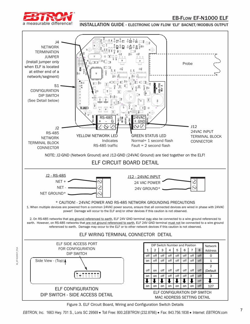
7EBTRON, Inc. 1663 Hwy. 701 S., Loris SC 29569 • Toll Free: 800.2EBTRON (232.8766) • Fax: 843.756.1838 • Internet: EBTRON.com 7Figure 3. ELF Circuit Board, Wiring and Configuration Switch Details
S1CONFIGURATION
DIP SWITCH(See Detail below)
ELF SIDE ACCESS PORTFOR CONFIGURATION
DIP SWITCH
ELF CONFIGURATION DIP SWITCH - SIDE ACCESS DETAIL
ELF CIRCUIT BOARD DETAIL
ELF WIRING TERMINAL CONNECTOR DETAIL
GREEN STATUS LEDNormal= 1 second flash Fault = 2 second flash
YELLOW NETWORK LEDIndicates
RS-485 traffic
J1224VAC INPUTTERMINAL BLOCKCONNECTOR
J4NETWORK
TERMINATIONJUMPER
(Install jumper onlywhen ELF is located
at either end of anetwork/segment)
J2RS-485
NETWORKTERMINAL BLOCK
CONNECTOR
NOTE: J2-GND (Network Ground) and J12-GND (24VAC Ground) are tied together on the ELF!
OFF
1 2 3 4 5 6 7 8
Side View - (Top)
J2 - RS-485NET +NET -
NET GROUND*
J12 - 24VAC INPUT24 VAC POWER 24V GROUND*
* CAUTION! - 24VAC POWER AND RS-485 NETWORK GROUNDING PRECAUTIONS1. When multiple devices are powered from a common 24VAC power source, ensure that all connected devices are wired in phase with 24VAC
power! Damage will occur to the ELF and/or other devices if this caution is not observed.
2. On RS-485 networks that are ground referenced to earth, ELF 24V GND terminal may also be connected to a wire ground referenced toearth. However, on RS-485 networks that are not ground referenced to earth, ELF 24V GND terminal must not be connected to a wire ground
referenced to earth. Damage may occur to the ELF or to other network devices if this caution is not observed.
Probe
1 2 3 4 5 6 7 8
off off off off off off off off 00on off off off off off off off 1
off oon off off off off off off2
(Defaulton on off off off off off off 33
offon on on on on on on off 127
MAC ADDRESS
DIP Switch Number and Position NetworkAddress
ELF CONFIGURATION DIP SWITCHMAC ADDRESS SETTING DETAIL
RS-485+ - G
24VAC+ GND
IG_E
F-N
100
0-T
_R1
A
a measurable difference!
®
EB-FLOW EF-N1000 ELFINSTALLATION GUIDE - ELECTRONIC LOW FLOW ‘ELF’ BACNET/MODBUS OUTPUT
EBTRON, Inc. 1663 Hwy. 701 S., Loris SC 29569 • Toll Free: 800.2EBTRON (232.8766) • Fax: 843.756.1838 • Internet: EBTRON.com8
IG_E
LF-D
_R1
E
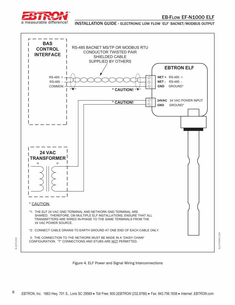
Figure 4. ELF Power and Signal Wiring Interconnections
BASCONTROL
INTERFACE
* CAUTION!
RS-485 -COMMON
RS-485 +
24 VACTRANSFORMER
EBTRON ELF
* CAUTION!
RS-485 BACNET MS/TP OR MODBUS RTU CONDUCTOR TWISTED PAIR
SHIELDED CABLESUPPLIED BY OTHERS
* CAUTION:
*1: THE ELF 24 VAC GND TERMINAL AND NETWORK GND TERMINAL ARESHARED. THEREFORE, ON MULTIPLE ELF INSTALLATIONS, ENSURE THAT ALLTRANSMITTERS ARE WIRED IN-PHASE TO THE SAME TERMINALS FROM THE 24 VAC POWER SOURCE.
*2: CONNECT CABLE DRAINS TO EARTH GROUND AT ONE END OF EACH CABLE ONLY.
3: THE CONNECTION TO THE NETWORK MUST BE MADE IN A “DAISY CHAIN” CONFIGURATION. “T” CONNECTIONS AND STUBS ARE NOT PERMITTED.
24VAC 24 VAC POWER INPUTGND GROUND*
NET - RS-485 -GND GROUND*
NET + RS-485 +
IG_E
F-N
100
0-T
_R1
A
a measurable difference!
®
EB-FLOW EF-N1000 ELFINSTALLATION GUIDE - ELECTRONIC LOW FLOW ‘ELF’ BACNET/MODBUS OUTPUT
EBTRON, Inc. 1663 Hwy. 701 S., Loris SC 29569 • Toll Free: 800.2EBTRON (232.8766) • Fax: 843.756.1838 • Internet: EBTRON.com 9
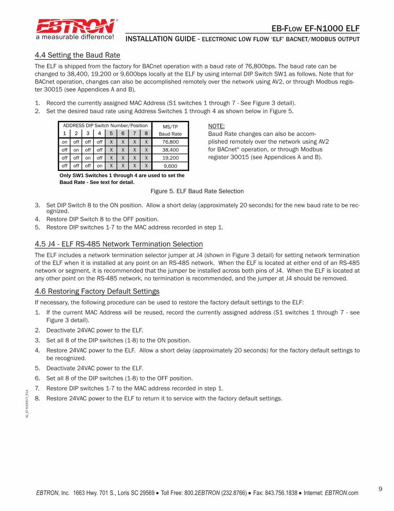
4.4 Setting the Baud RateThe ELF is shipped from the factory for BACnet operation with a baud rate of 76,800bps. The baud rate can bechanged to 38,400, 19,200 or 9,600bps locally at the ELF by using internal DIP Switch SW1 as follows. Note that forBACnet operation, changes can also be accomplished remotely over the network using AV2, or through Modbus regis-ter 30015 (see Appendices A and B).
1. Record the currently assigned MAC Address (S1 switches 1 through 7 - See Figure 3 detail). 2. Set the desired baud rate using Address Switches 1 through 4 as shown below in Figure 5.
3. Set DIP Switch 8 to the ON position. Allow a short delay (approximately 20 seconds) for the new baud rate to be rec-ognized.
4. Restore DIP Switch 8 to the OFF position.5. Restore DIP switches 1-7 to the MAC address recorded in step 1.
4.5 J4 - ELF RS-485 Network Termination SelectionThe ELF includes a network termination selector jumper at J4 (shown in Figure 3 detail) for setting network terminationof the ELF when it is installed at any point on an RS-485 network. When the ELF is located at either end of an RS-485network or segment, it is recommended that the jumper be installed across both pins of J4. When the ELF is located atany other point on the RS-485 network, no termination is recommended, and the jumper at J4 should be removed.
4.6 Restoring Factory Default SettingsIf necessary, the following procedure can be used to restore the factory default settings to the ELF:
1. If the current MAC Address will be reused, record the currently assigned address (S1 switches 1 through 7 - seeFigure 3 detail).
2. Deactivate 24VAC power to the ELF.
3. Set all 8 of the DIP switches (1-8) to the ON position.
4. Restore 24VAC power to the ELF. Allow a short delay (approximately 20 seconds) for the factory default settings tobe recognized.
5. Deactivate 24VAC power to the ELF.
6. Set all 8 of the DIP switches (1-8) to the OFF position.
7. Restore DIP switches 1-7 to the MAC address recorded in step 1.
8. Restore 24VAC power to the ELF to return it to service with the factory default settings.
1 2 3 4 5 6 7 8
on off off off X X X X 76,800off on off off X X X X 38,400off off on off X X X X 19,200off off off on X X X X 9,600
Baud Rate
ADDRESS DIP Switch Number/Position
Only SW1 Switches 1 through 4 are used to set the Baud Rate - See text for detail.
MS/TPBaud Rate
Figure 5. ELF Baud Rate Selection
NOTE:Baud Rate changes can also be accom-plished remotely over the network using AV2for BACnet® operation, or through Modbusregister 30015 (see Appendices A and B).
IG_E
F-N
100
0-T
_R1
A
a measurable difference!
®
EB-FLOW EF-N1000 ELFINSTALLATION GUIDE - ELECTRONIC LOW FLOW ‘ELF’ BACNET/MODBUS OUTPUT
EBTRON, Inc. 1663 Hwy. 701 S., Loris SC 29569 • Toll Free: 800.2EBTRON (232.8766) • Fax: 843.756.1838 • Internet: EBTRON.com10
5. ELF BACnet CONFIGURATIONThe following paragraphs detail the final set up instructions for the ELF when using BACnet device operation. The ELF-N1000 is shipped from the factory for BACnet operation. Default communication is set for 8 Data Bits, 1 Stop Bit andNo Parity.
For Modbus operation, proceed to ELF MODBUS CONFIGURATION section 6 of this document.
Refer to Appendix A - ELF BACnet Object properties for additional detail.
5.1 Changing BACnet Device Object Instance Number
5.1.1 Matching BACnet Device Object Instance Number to MAC AddressThe BACnet Device Object Instance Number is set at the factory to match the default MAC address of 2. If necessary,the BACnet Device Object Instance Number can be set to match a different user assigned MAC address, as follows:
1. Set the user assigned MAC address value as previously described in Setting the MAC Address procedure.
2. Deactivate 24VAC power to the ELF.
3. Slide DIP Switch 8 to the ON position.
4. Restore 24VAC power to the ELF. Allow a short delay (approximately 20 seconds) for the new BACnet Device ObjectInstance Number to be recognized.
5. Restore DIP Switch 8 to the OFF position.
5.1.2 Setting BACnet Device Object Instance Number to a value different than MAC AddressThe BACnet Device Object Instance Number can be set to a value that does not match the MAC address by using suit-able BACnet software to write to the ELF Device Object Identifier property of the Device Object. Refer to Appendix A foradditional detail.
6. ELF MODBUS CONFIGURATIONThe ELF is preset at the factory for BACnet network operation. Default communication is set for 8 Data Bits, 1 Stop Bitand No Parity. To set the ELF for Modbus network operation, perform the following steps. Refer to Appendix B - ELF MOD-BUS Register Map for available register values and settings.
1. The default network address is set at the factory for a value of 2. Any value between 1 and 127 can be assigned forthe ELF using Configuration DIP Switch S1 as outlined in the Setting the MAC Address paragraph of this document.If the current network address will be reused, record the current settings of DIP switches 1 through 7.
2. With the ELF powered on, set Configuration DIP switches 1 through 4 to the ON position.
3. Toggle DIP switch 8 to the ON position for 5 seconds, and then back to OFF.
4. Restore DIP switches 1-7 to the network address recorded in step 1.
5. The ELF is now set for Modbus operation with a baud rate of 19,200bps. If necessary, the baud rate can be changedas outlined previously in the Setting the Baud Rate paragraph of this document.
6. Configure the necessary Modbus register values as outlined in Appendix B.
IG_E
F-N
100
0-T
_R1
A
a measurable difference!
®
EB-FLOW EF-N1000 ELFINSTALLATION GUIDE - ELECTRONIC LOW FLOW ‘ELF’ BACNET/MODBUS OUTPUT
EBTRON, Inc. 1663 Hwy. 701 S., Loris SC 29569 • Toll Free: 800.2EBTRON (232.8766) • Fax: 843.756.1838 • Internet: EBTRON.com 11
7. ELF INITIAL START UP / NORMAL OPERATIONThe following procedure is intended for initial start up of the instrument. Following the initial set up, no further user activ-ity is required during normal operation.
1. Remove the cover to the electronics enclosure by removing the four screws on the cover.
2. Make sure that the 24VAC circuit breaker used to power the ELF is turned OFF until all wiring is complete!
3. Confirm 24VAC connections to the ELF power connector J12.
4. Confirm that the ELF’s common 24VAC ground and network ground connection are permitted.
5. Note that the ground of the BAS must be at the same voltage reference as the ground of the ELF and the powersource.
6. Confirm the settings of CONFIG switches SW1 to SW7 as outlined in paragraphs 4.1 through 4.3 of this document.
7. Activate the 24VAC power source to power on the ELF.
8. Following a brief instrument initialization, the green Activity LED will continuously flash ON for 1 second, then OFFfor 1 second. This indicates normal operation. In the event of a sensor fault, the LED will produce longer continu-ous flashes ON for 2 seconds, and OFF for 2 seconds.
9. Confirm that the yellow RS-485 Network LED is blinking indicating traffic between the ELF and the BAS network.Also, verify instrument airflow (or equivalent velocity pressure) and temperature at the BAS control interface.
10. Replace the ELF electronics enclosure cover and secure with the four screws removed in step 1.
8. FOR ADDITIONAL INFORMATIONRefer to the separate Installation, Operation and Maintenance Technical Manual TM_EF-x1000-D for additional informa-tion, or contact your local EBTRON representative or our Technical Support Team at 800.2EBTRON (1.800.232.8766).
IG_E
F-N
100
0-T
_R1
A
a measurable difference!
®
EB-FLOW EF-N1000 ELFINSTALLATION GUIDE - ELECTRONIC LOW FLOW ‘ELF’ BACNET/MODBUS OUTPUT
EBTRON, Inc. 1663 Hwy. 701 S., Loris SC 29569 • Toll Free: 800.2EBTRON (232.8766) • Fax: 843.756.1838 • Internet: EBTRON.com12
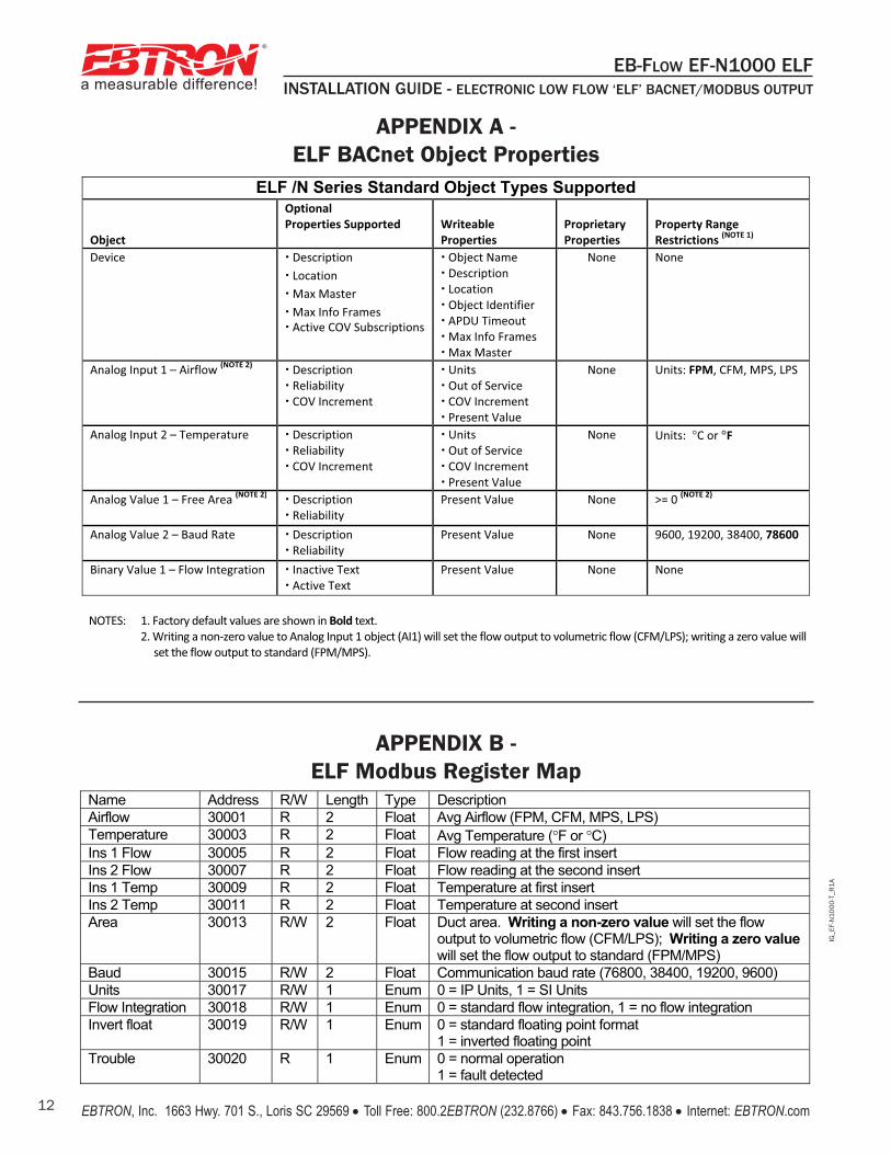
ELF /N Series Standard Object Types Supported Object
Optional Properties Supported
Writeable Properties
Proprietary Properties
Property Range Restrictions (NOTE 1)
Device � Description � Location � Max Master � Max Info Frames � Active COV Subscriptions
� Object Name � Description � Location � Object Identifier � APDU Timeout � Max Info Frames � Max Master
None None
Analog Input 1 – Airflow (NOTE 2) � Description � Reliability � COV Increment
� Units � Out of Service � COV Increment � Present Value
None Units: FPM, CFM, MPS, LPS
Analog Input 2 – Temperature � Description � Reliability � COV Increment
� Units � Out of Service � COV Increment � Present Value
None Units: °C or °F
Analog Value 1 – Free Area (NOTE 2) � Description � Reliability
Present Value None >= 0 (NOTE 2)
Analog Value 2 – Baud Rate � Description � Reliability
Present Value None 9600, 19200, 38400, 78600
Binary Value 1 – Flow Integration � Inactive Text � Active Text
Present Value None None
NOTES: 1. Factory default values are shown in Bold text.
2. Writing a non-zero value to Analog Input 1 object (AI1) will set the flow output to volumetric flow (CFM/LPS); writing a zero value will set the flow output to standard (FPM/MPS).
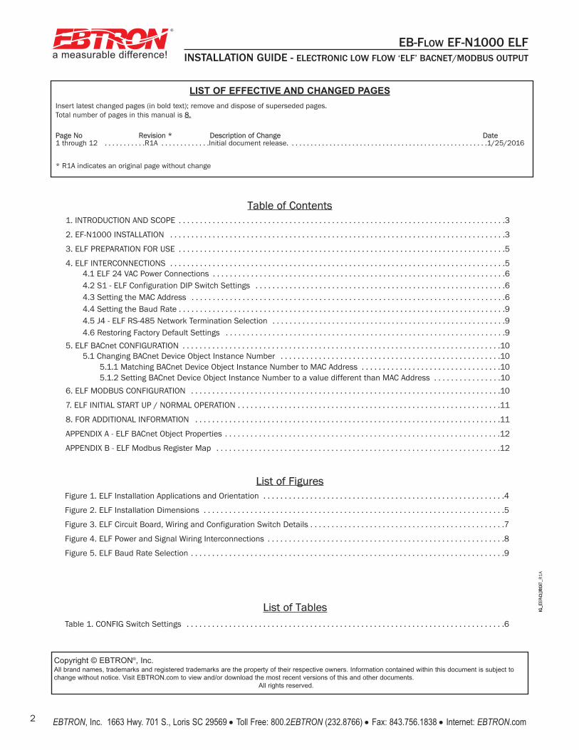
Name Address R/W Length Type Description Airflow 30001 R 2 Float Avg Airflow (FPM, CFM, MPS, LPS) Temperature 30003 R 2 Float Avg Temperature (°F or °C) Ins 1 Flow 30005 R 2 Float Flow reading at the first insert Ins 2 Flow 30007 R 2 Float Flow reading at the second insert Ins 1 Temp 30009 R 2 Float Temperature at first insert Ins 2 Temp 30011 R 2 Float Temperature at second insert Area 30013 R/W 2 Float Duct area. Writing a non-zero value will set the flow
output to volumetric flow (CFM/LPS); Writing a zero value will set the flow output to standard (FPM/MPS)
Baud 30015 R/W 2 Float Communication baud rate (76800, 38400, 19200, 9600) Units 30017 R/W 1 Enum 0 = IP Units, 1 = SI Units Flow Integration 30018 R/W 1 Enum 0 = standard flow integration, 1 = no flow integration Invert float 30019 R/W 1 Enum 0 = standard floating point format
1 = inverted floating point Trouble 30020 R 1 Enum 0 = normal operation
1 = fault detected
APPENDIX A - ELF BACnet Object Properties
APPENDIX B - ELF Modbus Register Map