Embed Size (px)
Citation preview

8/10/2019 Thermal Conduction4
http://slidepdf.com/reader/full/thermal-conduction4 1/32
EML 4304L Thermal Fluids Lab Thermal Conduction
Experiment # 3
Mechanical Engineering DepartmentFAMU/FSU College of Engineering

8/10/2019 Thermal Conduction4
http://slidepdf.com/reader/full/thermal-conduction4 2/32
Outline
•Purpose of the lab•Fundamental Equations
•Unit 3 and Unit 4 Analysis
•Unit 1 and Unit 2 Analysis•Error Analysis

8/10/2019 Thermal Conduction4
http://slidepdf.com/reader/full/thermal-conduction4 3/32
PURPOSE
• Conduct a series of thermal conductionexperiments which examines the effects on heattransfer with varying cross-sectional area anddistance.
– Using this thermal conduction information derive Fourier’s law of thermal conduction.
• Analyze the temperature variance in a series ofmetal rods that are in physical contact.
– From this information determine thermal resistanceand contact resistance.

8/10/2019 Thermal Conduction4
http://slidepdf.com/reader/full/thermal-conduction4 4/32
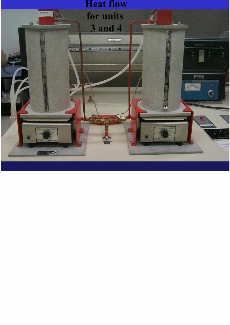
Heat flow
for units
3 and 4
Q conduction=-k A dT / dx
Q coolant=m Cp dT / t
H fl

8/10/2019 Thermal Conduction4
http://slidepdf.com/reader/full/thermal-conduction4 5/32
Heat flow
for units
1 and 2

8/10/2019 Thermal Conduction4
http://slidepdf.com/reader/full/thermal-conduction4 6/32
Fundamental
Equations

8/10/2019 Thermal Conduction4
http://slidepdf.com/reader/full/thermal-conduction4 7/32
Rate of heat flow at the heat sink
mw = mass of cooling water displaced in time t (kg)
C p = Specific heat of water at constant pressure (kJ/kg °C)
T = (Tout - T in ) of cooling water (°C)
t = time required to displace a volume V w of water (s)
This equation is used to determine the amount of energy that isbeing absorbed by the coolant. Once this is determined for each
uni t, it is assumed to be the constant rate of conduction through
each mater ial.
t
T C m
q
pw

8/10/2019 Thermal Conduction4
http://slidepdf.com/reader/full/thermal-conduction4 8/32
Qcond = KA(ΔT/Δx)
Rate of heat conduction
K = thermal conductivity constant (W/m °C)
A = cross-sectional area (m2)
T = temperature difference across the material (°C)
x = distance between temperature readings (m)
Used to determine rate of heat conduction through
a body based on material properties, area,
temperature difference, and length of material.

8/10/2019 Thermal Conduction4
http://slidepdf.com/reader/full/thermal-conduction4 9/32
Fourier’s law of heat conduction
-K = thermal conductivity constant (W/m °C)
A = cross-sectional area (m2)
dT = differential element for temperature (°C)
dx = differential element for distance (m)
Qcond = -KA dT/dx
Used to determine rate of heat conduction through a body
based on material properties, area, and temperature/distance
gradient.

8/10/2019 Thermal Conduction4
http://slidepdf.com/reader/full/thermal-conduction4 10/32
• Q=KA ΔT/Δx Q=-KA dT/dx
• dT/dx = temperature gradient
x
T
dT/dx
8/10/2019 Thermal Conduction4
http://slidepdf.com/reader/full/thermal-conduction4 11/32
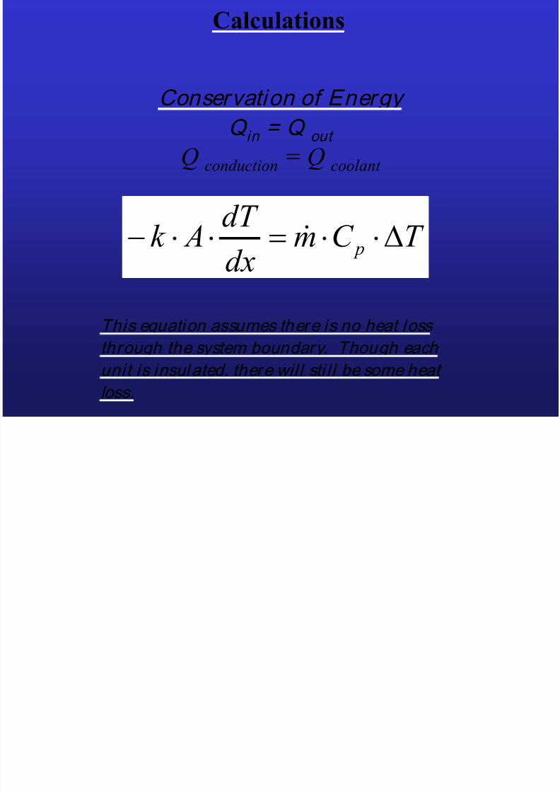
Conservation of EnergyQ in = Q out
Q conduction = Q coolant
Calculations
This equation assumes there is no heat loss
through the system boundary. Though each
unit is insulated, there will sti l l be some heat
loss.
T C mdx
dT Ak p

8/10/2019 Thermal Conduction4
http://slidepdf.com/reader/full/thermal-conduction4 12/32
Thermal Contact Resistance
R t,c
= Thermal contact resistance (ºC/W)
T = Temperature change (ºC)
q = Heat flux (W)
R T
qt c,
Calculates thermal contact resistance for a
given temperature discontinuity and a known
power input.

8/10/2019 Thermal Conduction4
http://slidepdf.com/reader/full/thermal-conduction4 13/32
Heat Conduction
for Units 3 and 4

8/10/2019 Thermal Conduction4
http://slidepdf.com/reader/full/thermal-conduction4 14/32
Thermocouple Placement
for Units 3 and 4

8/10/2019 Thermal Conduction4
http://slidepdf.com/reader/full/thermal-conduction4 15/32
UNIT #3Q=KA*ΔT/Δx
Diameter is a function of x:
D(x)=D0+mx
D(x)=1”+(x/(11+1/16))

8/10/2019 Thermal Conduction4
http://slidepdf.com/reader/full/thermal-conduction4 16/32
Unit #3
Area can also be written as
a function of x:
A = (p/4) d2
A(x) = (p/4) d(x)2
Q=KA*dT/dx

8/10/2019 Thermal Conduction4
http://slidepdf.com/reader/full/thermal-conduction4 17/32
Unit #3
Q = -k A T/x = -k A(x) dT/dx
Q k A x( )dT
dx
Q x1
A x( )
d k 1
d

8/10/2019 Thermal Conduction4
http://slidepdf.com/reader/full/thermal-conduction4 18/32
Unit #3
Once k is solved for, the temperaturecan be found for any distance, x.
T x( ) T 0Q
k
1
A x( )
d
0
)(
1
T T
dx x AQk

8/10/2019 Thermal Conduction4
http://slidepdf.com/reader/full/thermal-conduction4 19/32
UNIT #4
x2 x1
QinQout
Q=KA*ΔT/Δx
K = coeff. of therm. conductivity NOTE: K is
unknown andmust be
determined

8/10/2019 Thermal Conduction4
http://slidepdf.com/reader/full/thermal-conduction4 20/32
Thermal ContactResistance
Determination Units#1 and #2
8/10/2019 Thermal Conduction4
http://slidepdf.com/reader/full/thermal-conduction4 21/32
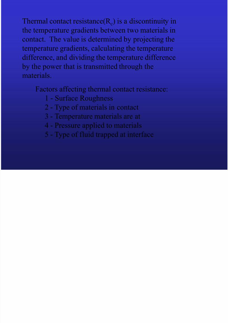
Thermal contact resistance(R c) is a discontinuity in
the temperature gradients between two materials in
contact. The value is determined by projecting thetemperature gradients, calculating the temperature
difference, and dividing the temperature difference
by the power that is transmitted through the
materials.
Factors affecting thermal contact resistance:
1 - Surface Roughness
2 - Type of materials in contact
3 - Temperature materials are at4 - Pressure applied to materials
5 - Type of fluid trapped at interface

8/10/2019 Thermal Conduction4
http://slidepdf.com/reader/full/thermal-conduction4 22/32
elements are enclosed in the insulating jacket. Figure1 illustrates the schematics of the apparatus. The dimensions of the tapered rod are indicated
in Fig. 2.
elements are enclosed in the insulating jacket. Figure1 illustrates the schematics of the apparatus. The dimensions of the tapered rod are indicated
in Fig. 2.
elements are enclosed in the insulating jacket. Figure1 illustrates the schematics of the apparatus. The dimensions of the tapered rod are indicated
in Fig. 2.

8/10/2019 Thermal Conduction4
http://slidepdf.com/reader/full/thermal-conduction4 23/32
Units #1 and #2
Cu
(Al)
Contact Resistance
T1T10
x1x2
Stainless
Steel
Steel
(Mg)

8/10/2019 Thermal Conduction4
http://slidepdf.com/reader/full/thermal-conduction4 24/32

8/10/2019 Thermal Conduction4
http://slidepdf.com/reader/full/thermal-conduction4 25/32
Ideal Thermal Conduction
T1
T2
T3
T4
Material 1 Material 2
T2 = T3

8/10/2019 Thermal Conduction4
http://slidepdf.com/reader/full/thermal-conduction4 26/32
Actual Thermal Conduction
T1T2
T3
T4
Material 1 Material 2
T2 = T3
Temperature
profile due to
thermalcontact
resistance

8/10/2019 Thermal Conduction4
http://slidepdf.com/reader/full/thermal-conduction4 27/32
Material 1 Material 2
T2
T3
Projected
Slope T3
Projected
Slope T2
ΔT
Temperature profile due
to thermal contact
resistance

8/10/2019 Thermal Conduction4
http://slidepdf.com/reader/full/thermal-conduction4 28/32
Temperature vs Distance
Temperature(ºF)
Distance(inches)
Material 1
Material 2
Material 3
Discontinuities
where ΔT must be determined

8/10/2019 Thermal Conduction4
http://slidepdf.com/reader/full/thermal-conduction4 29/32
Thermal Contact Resistance
Calculation
R t,c = ΔT/Q
Qwtr =mwC p(ΔT)
Q = Qwtr
ΔT (determined by projection of slope
and measuring difference in
temperatures)

8/10/2019 Thermal Conduction4
http://slidepdf.com/reader/full/thermal-conduction4 30/32
Errors
• Time
Flow rate
Steady State
• Heat Losses
Not perfectly insulated
• Unit #4 Thermocouples #3 and #5Inconsistent readings

8/10/2019 Thermal Conduction4
http://slidepdf.com/reader/full/thermal-conduction4 31/32
Heat flow
8/10/2019 Thermal Conduction4
http://slidepdf.com/reader/full/thermal-conduction4 32/32
Heat flowfor units
3 and 4