Embed Size (px)
Citation preview

Theory of turbo machinery / Turbomaskinernas teori
Dixon, chapter 9
Hydraulic Turbines

Hear ye not the hum of mighty workings? (KEATS, Sonnet No. 14).
The power of water has changed more in this world than emperors or kings.
(Leonardo da Vinci).
http://www.youtube.com/watch?v=HzQPNpP55xQ
LTH / Kraftverksteknik / JK
Hydraulic Turbines
Todays topics Introduction; Where and how much Types of turbines
Pelton Francis Kaplan

LTH / Kraftverksteknik / JK
Hydraulic Turbines, potential

LTH / Kraftverksteknik / JK
Land Produktion TWh
Per capita
Andel av elproduktion
Förändring mot 1995-2000
Kanada 344 -1%
Kina 321 +58%
Brasilien 304 +6%
USA 260 -20%
Ryssland 170 +7%
Norge 121 99% +1%
Syrien 119 +2%
Japan 96 +2%
Indien 78 +2%
Frankrike 67 -6%
Venezuela 66 +12%
Sverige 65 ~ 50% -6%
Wikipedia: Produktion 2000-2005
Hydraulic Turbines, production

LTH / Kraftverksteknik / JK
Hydraulic Turbines, large plants
De största svenska kraftverken är: • Harsprånget i Luleälven (945 MW) • Stornorrfors i Umeälven • Messaure i Luleälven
Name Country Year of completion
Total Capacity (MW)
Max annual electricity production (TW-hour)
Area flooded (km²)
Three Gorges Dam
China 2012 22,500 (when complete)
>100 1,045
Itaipu Brazil/Paraguay
1984/1991/2003 14,000 90 1,350
Guri (Simón Bolívar)
Venezuela 1986 10,200 46 4,250
Three Gorges Dam
LTH / Kraftverksteknik / JK
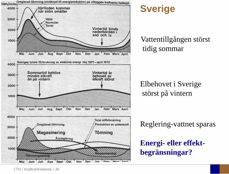
Sverige
Vattentillgången störst tidig sommar
Elbehovet i Sverige störst på vintern
Reglering-vattnet sparas
Energi- eller effekt- begränsningar?
LTH / Kraftverksteknik / JK
Hydraulic Turbines
• Utbyggnaden av kraftverk i älvar och floder får stora konsekvenser för den biologiska mångfalden när stora områden sätts under vatten.
• Lekområden för fisk ödeläggs och vattenorganismer såväl som ett flertal andra växter, fåglar och djur påverkas negativt.
Greenpeace (hemsida*): Fler stora vattenkraftsutbyggnader är inte försvarbara ur biologisk och ekologisk synpunkt:
* http://www.greenpeace.org/sweden/kampanjer/klimat/losningar/klimatvanlig-energi/vatten
Småskalig vattenkraft å andra sidan fångar flodernas energi utan att ta bort för mycket vatten från deras naturliga flöde. Därför är den småskaliga vattenkraften en miljövänlig energikälla med stor tillväxtpotential.
LTH / Kraftverksteknik / JK
Hydraulic Turbines
Regeringen De fyra outbyggda huvudälvarna* ska bevaras
*Nationalälvarna: Torne, Kalix, Pite och Vindelälven
STEM Vattenkraft är en ren energikälla som ger stora mängder energi. Att anlägga nya vattenkraftverk orsakar dock stora skador i naturen. Därför byggs inga nya större kraftverk i vårt land.

LTH / Kraftverksteknik / JK
Hydraulic Turbines
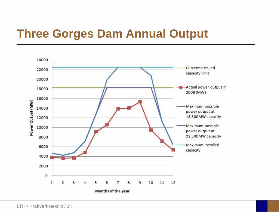
3 Gorges Dam The Three Gorges Project, including a 2,309-meter-long, 185-meter-high dam with 26 power generators, is being built on the middle reaches of the Yangtze, China's longest river. The project started 1993 and is assumed to be finished 2011, at what time the power output will be 22 500 MW. Water from upstream is flowing into the reservoir at a rate of 13,200 cubic meters per second.
http://maps.google.com/maps?ll=30.83,111.01&spn=0.01,0.01&t=h&q=30.83,111.01
LTH / Kraftverksteknik / JK
Three Gorges Dam Annual Output

LTH / Kraftverksteknik / JK
Increasing electricity demand

LTH / Kraftverksteknik / JK
Flooded area

LTH / Kraftverksteknik / JK
Characteristics

LTH / Kraftverksteknik / JK
Main types of Hydraulic Turbines

LTH / Kraftverksteknik / JK
Hydraulic Turbines
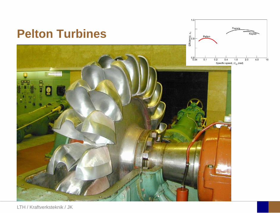
FIG. 9.1. Typical design point efficiencies of Pelton, Francis and Kaplan turbines.
sp
s
Ωη
Ω=
( )( )
1/ 2
5/ 4
/sp
P
gH
Ω ρΩ =
( )
1/ 2
3/ 4sQ
gHΩΩ =

LTH / Kraftverksteknik / JK
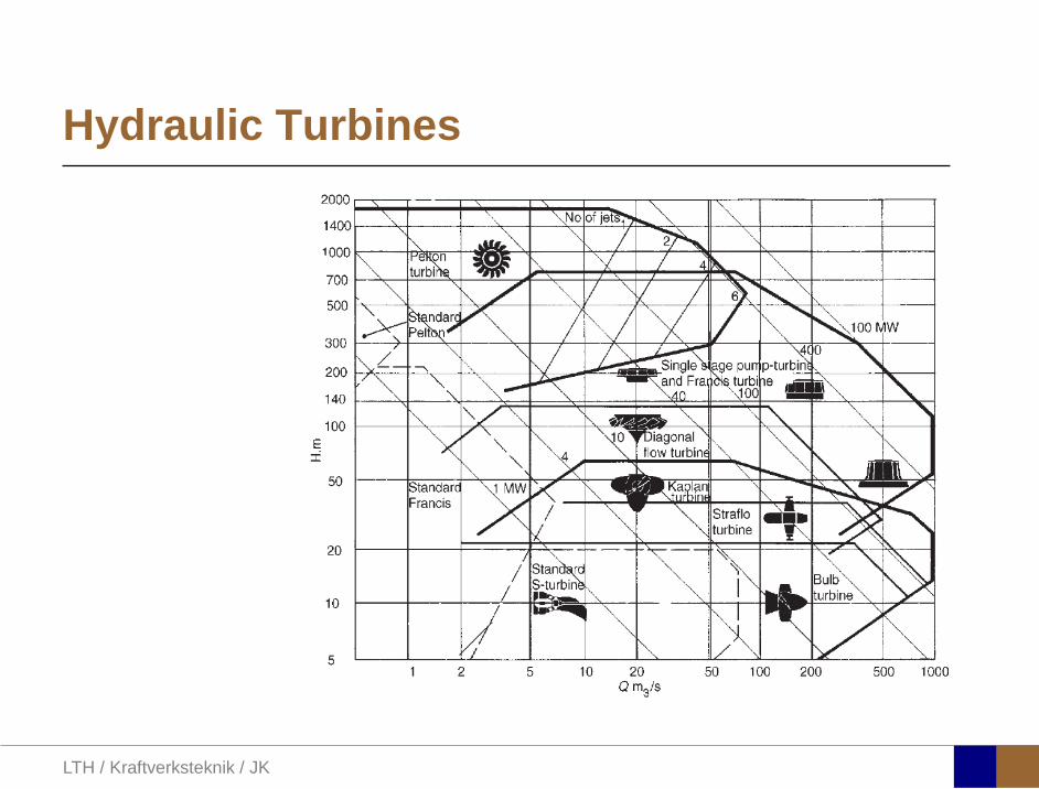
Hydraulic Turbines
LTH / Kraftverksteknik / JK
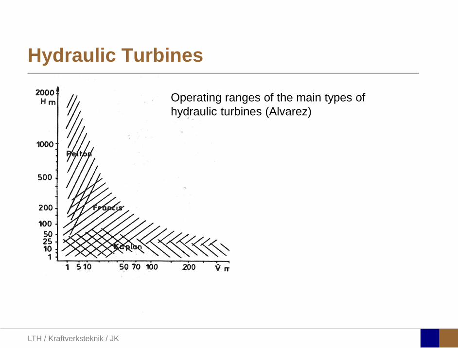
Hydraulic Turbines
Operating ranges of the main types of hydraulic turbines (Alvarez)
LTH / Kraftverksteknik / JK
Hydraulic Turbines

LTH / Kraftverksteknik / JK
Hydraulic Turbines
Ohakuri Dam Blue Penstocks
LTH / Kraftverksteknik / JK
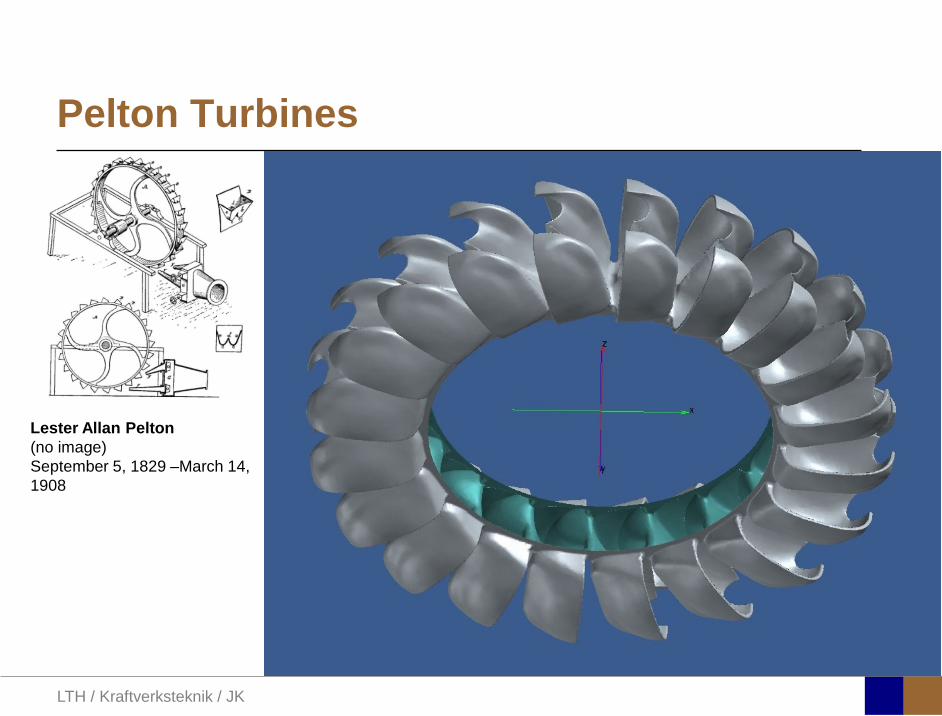
Pelton Turbines
LTH / Kraftverksteknik / JK
Pelton Turbines
Lester Allan Pelton (no image) September 5, 1829 –March 14, 1908

LTH / Kraftverksteknik / JK
Pelton Turbines
FIG. 9.5. The Pelton wheel showing the jet impinging onto a bucket and the relative and absolute velocities of the flow (only one-half of the emergent velocity diagram is shown).

LTH / Kraftverksteknik / JK
Pelton Turbines
1 1 2 2ΔW U c U cθ θ= −
( ) ( )1 2 2 1 2 2Δ cos cosW U U w U w U w wβ β = + − + = −
From Eulers turbine equation
For the Pelton turbine:
1 2U U U= =
and thus Euler becomes
1 1 1c c U wθ = = +
2 2 2cosc U wθ β= +2β
2cos 0β <

LTH / Kraftverksteknik / JK
Pelton Turbines
2 1w kw=
where k is a loss factor less than 1. Introducing this into Eulers eq.:
( )21 2
1 1
2Δ c 2 1 1 cosRU UW kc c
η β
= = − −
Friction looses are accounted for by relating relative velocities
Dividing by the available energy, , yields a “runner” efficiency: 21 2c
( ) ( )( )1 2 1 21 cos 1 cosW Uw k U c U k∆ β β= − = − −

LTH / Kraftverksteknik / JK
Pelton Turbines
FIG. 9.6. Theoretical variation of runner efficiency for a Pelton wheel with blade speed to jet speed ratio for several values of friction factor k .
2 165β =
,max
1
@
0.5
R
Uc
η
ν= =
Cos is a forgiving function:
( )cos 1650.966
=
= −

LTH / Kraftverksteknik / JK
Pelton Turbines
FIG. 9.7. Pelton turbine hydroelectric scheme.
Surge tank reduces pressure spikes Gross head:
G R NH z z= −
Effective head:
( )E G F rictionH H H= −

LTH / Kraftverksteknik / JK
Pelton Turbines
More losses:
• Friction losses in penstock (pipe flow: moody chart) • Nozzle efficiency • Bearing friction and windage, assumed proportional to the
square of the blade speed:
( )21 2N Ec gHη =
2KU
An overall efficiency of the machine (excluding penstock) may be defined:
22
0 21
... 2N RE
W KU UKgH c
∆η η η − = = = −

LTH / Kraftverksteknik / JK
Pelton Turbines
FIG. 9.9. Variation of overall efficiency of a Pelton turbine with speed ratio for several values of windage coefficient, K .
The subtraction of energy by the U2 term displaces the optimum blade speed to jet speed ratio

LTH / Kraftverksteknik / JK
Pelton Turbines, controle
FIG. 9.8. Methods of regulating the speed of a Pelton turbine: (a) with a spear (or needle) valve; (b) with a deflector plate.
Spear used for slow control
Deflector plate causes no “hammer”

LTH / Kraftverksteknik / JK
Pelton Turbines, part load
FIG. 9.10. Pelton turbine overall efficiency variation with load under constant head and constant speed conditions.
Controle by adjustment of needle valve: Hydraulic losses reduced at low load, but bearings and windage losses remain at constant speed

LTH / Kraftverksteknik / JK
Francis Turbines
James Bicheno Francis May 18, 1815 – September 18, 1892
LTH / Kraftverksteknik / JK
Francis Turbines
Reaction turbines Part of the pressure drop takes place in the turbine itself (Runner) Water flow completely fills all part of the turbine Pivotable guide vanes are used for control (Francis) A draft tube is normally added on to the exit; it is considered an
integral part of the turbine

LTH / Kraftverksteknik / JK
Francis Turbines
FIG. 9.16. Location of draft tube in relation to vertical shaft Francis turbine.
Draft tube Shaped as a diffusor to minimize losses Turbine may be placed above tailwater surface Cavitation may be an issue
LTH / Kraftverksteknik / JK
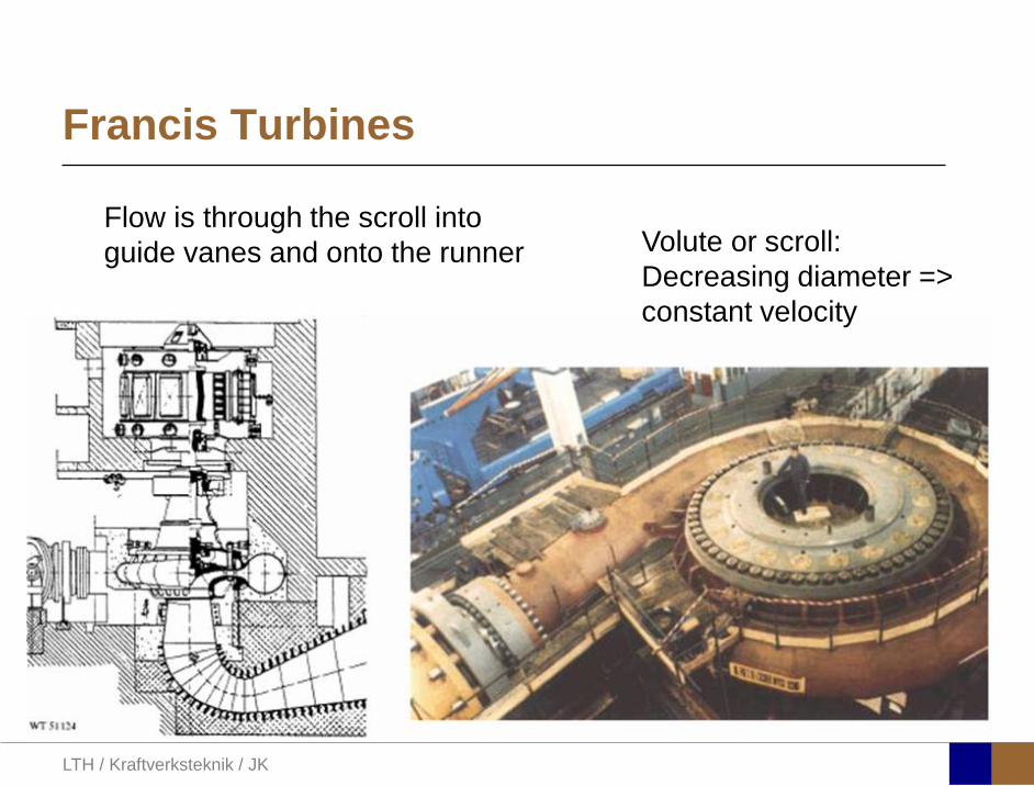
Francis Turbines
Volute or scroll: Decreasing diameter => constant velocity
Flow is through the scroll into guide vanes and onto the runner

LTH / Kraftverksteknik / JK
Francis Turbines
Euler turbine equation
2 2 3 3ΔW U c U cθ θ= −
If there is no swirl at exit (design point):
2 2ΔW U cθ=
Slip is present

LTH / Kraftverksteknik / JK
Francis Turbines, control
FIG. 9.14. Comparison of velocity triangles for a Francis turbine for full load and at part load operation.
Volume flow rate reduced by guide vanes Blade speed retained Rotor incidence high. Swirl at exit increases losses and risk for cavitation (why?)

LTH / Kraftverksteknik / JK
Kaplan Turbines
Viktor Kaplan November 27, 1876 – August 23, 1934
LTH / Kraftverksteknik / JK
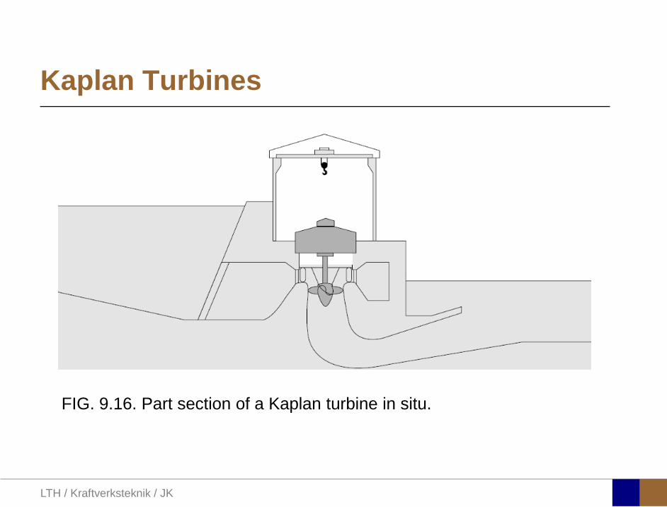
Kaplan Turbines
FIG. 9.16. Part section of a Kaplan turbine in situ.

LTH / Kraftverksteknik / JK
Kaplan Turbines (Voith Siemens)
Cross section of a 9.5 m diameter Kaplan runner for the Yacyretá hydropower plant in Argentina
Yacyretà, Argentina
LTH / Kraftverksteknik / JK
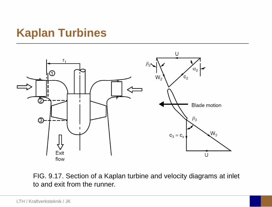
Kaplan Turbines
FIG. 9.17. Section of a Kaplan turbine and velocity diagrams at inlet to and exit from the runner.
LTH / Kraftverksteknik / JK
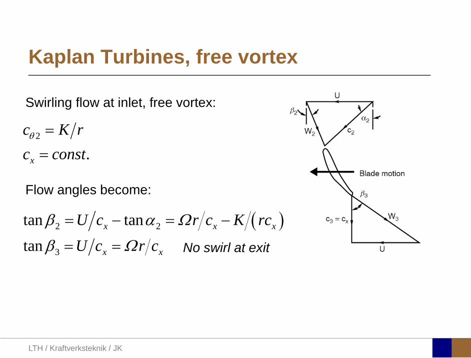
Kaplan Turbines, free vortex
Swirling flow at inlet, free vortex:
2
.x
c K rc constθ ==
Flow angles become:
( )2 2
3
tan tantan
x x x
x x
U c r c K rcU c r c
β α Ω
β Ω
= − = −
= = No swirl at exit
LTH / Kraftverksteknik / JK
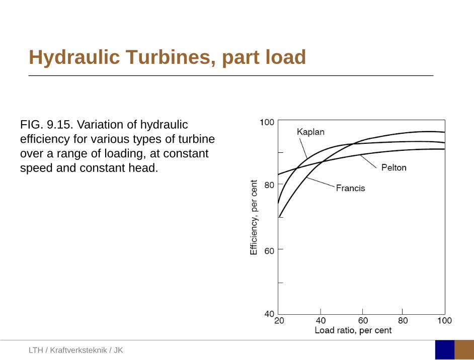
Hydraulic Turbines, part load
FIG. 9.15. Variation of hydraulic efficiency for various types of turbine over a range of loading, at constant speed and constant head.

LTH / Kraftverksteknik / JK
Hydraulic Turbines, cavitation
Two types: On the suction side of the runner near outlet On the centerline of the draft tube at off-design operation
(Francis)
Mental experiment: If you would like to pump up water from a well, where should you place the pump?
z

LTH / Kraftverksteknik / JK
Hydraulic Turbines, cavitation
The Thoma cavitation coefficient may be defined as
( ) ( )a
E E
p p g zNPSHH H
υ ρσ
− −= =
(Effective head) ( )E G F rictionH H H= −
where
ap Atmospheric pressure
( )Tpv Vapor pressure

LTH / Kraftverksteknik / JK
Cavitation

LTH / Kraftverksteknik / JK
Cavitation
FIG. 9.21. Variation of critical cavitation coefficient with non-dimensional specific speed for Francis and Kaplan turbines (adapted from Moody and Zowski 1969).

LTH / Kraftverksteknik / JK
Volatility of vind power
Electric power output of Spanish wind turbines, January 4 till January 26 (incl.), 2010.

LTH / Kraftverksteknik / JK
Backup power – Hydro well suited, but grids need strengthening – Gas turbines and GTCC have high ramp rates – Ramping of Nuclear and Coal
Storage - Expensive and/or low return efficiencies
“Smoothing”? Time and lengths scale are large Changing consumption
How do we cope with the temporal mismatch from volatile sources?

LTH / Kraftverksteknik / JK
Alqueva 2 (pump storage)
Owner: Empresa de Desenvolvimento e Infra-estruturas do Alqueva, S.A. (EDIA)
Location: Alqueva, Portugal River: Guadiana Capacity: 240 MW (Scheduled) On-Line Date: 2012 Estimated Development Cost: 167 million euro Description: Expansion of existing 259.2-mw
Alqueva, which has been operating since 2003. Development involves construction of a second powerhouse 39.7 meters wide by 79.1 meters long. The powerhouse will contain two 120-mw units, with a maximum water intake of 400 cubic meters per second.
Service and Product Suppliers Involved: Alstom Hydro, EFACEC Engenharia S.A., SMM, Sociedade de Construcoes Soares da Costa SA, Zagope Construcoes e Engenharia
LTH / Kraftverksteknik / JK