Embed Size (px)
Citation preview
Finite Element Formulation for Plates- Handout 4 -
Dr Fehmi Cirak (fc286@)
Completed Version

F CirakPage 72
■ The extension of Timoshenko beam theory to plates is the Reissner-Mindlinplate theory
■ In Reissner-Mindlin plate theory the out-of-plane shear deformations arenon-zero (in contrast to Kirchhoff plate theory)
■ Almost all commercial codes (Abaqus, LS-Dyna, Ansys, …) use Reissner-Mindlin type plate finite elements
■ Assumed displacements during loading
■ Kinematic assumption: a plane section originally normal to the mid-surface remains plane, but inaddition also shear deformations occur
Kinematics of Reissner-Mindlin Plate -1-
reference
deformed
undeformed and deformed geometries along one of the coordinate axis

F CirakPage 73
■ Kinematic equations■ In plane-displacements
■ In this equation and in following all Greek indices only take values 1 or 2
■ It is assumed that rotations are small
■ Rotation angle of normal:
■ Angle of shearing:
■ Slope of midsurface:
■ Out-of-plane displacements
■ The independent variables of the Reissner-Mindlin plate theory are therotation angle and mid-surface displacement
■ Introducing the displacements into the strain equation of three-dimensionalelasticity leads to the strains of the plate
Kinematics of Reissner-Mindlin Plate -2-

F CirakPage 74
■ Axial strains and in-plane shear:
■ Out-of-plane shear:
■ Note that always
■ Through-the-thickness strain:
■ The plate strains introduced into the internal virtual work of three-dimensional elasticity give the internal virtual work of the plate
■ with virtual displacements and rotations:
Weak Form of Reissner-Mindlin Plate -1-

F CirakPage 75
■ Definition of bending moments:
■ Definition of shear forces:
■ External virtual work■ Distributed surface load
■ Weak form of Reissner-Mindlin plate
■ As usual summation convention applies
Weak Form of Reissner-Mindlin Plate -2-

F CirakPage 76
■ Constitutive equations■ For bending moments (same as Kirchhoff plate)
■ For shear forces
■ Note that the curvature is a function of rotation angleand the shear angle is a function of rotation angle and the mid-surface displacement
Weak Form of Reissner-Mindlin Plate -3-

F CirakPage 77
■ The independent variables in the weak form are and thecorresponding test functions
■ Weak form contains only so that C0-interpolation is sufficient■ Usual (Lagrange) shape functions such as used in 3D7 can be used
■ Nodal values of variables:
■ Nodal values test functions:
■ Interpolation equations introduced into the kinematic equations yield
Finite Element Discretization -1-
four-node isoparametricelement

F CirakPage 78
■ Constitutive equations in matrix notation
■ Bending moments:
■ Shear forces:
■ Element stiffness matrix of a four-node quadrilateral element■ Bending stiffness (12x12 matrix)
Finite Element Discretization -2-

F CirakPage 79
■ Shear stiffness (12x12 matrix)
■ Element stiffness matrix
■ The integrals are evaluated with numerical integration. If too few integration points are used,element stiffness matrix will be rank deficient.
■ The necessary number of integration points for the bilinear element are 2x2 Gauss points
■ The global stiffness matrix and global load vector are obtained byassembling the individual element stiffness matrices and loadvectors■ The assembly procedure is identical to usual finite elements
Finite Element Discretization -3-

F CirakPage 80
■ As discussed for the Bernoulli and Timoshenko beams with increasing plateslenderness physics dictates that shear deformations have to vanish(i.e., )
■ Reissner-Mindlin plate and Timoshenko beam finite elements have problems to approximatedeformation states with zero shear deformations (shear locking problem)
■ 1D example: Cantilever beam with applied tip moment
■ Bending moment and curvature constant along the beam■ Shear force and hence shear angle zero along the beam■ Displacements quadratic along the beam
■ Discretized with one two-node Timoshenko beam element
Shear Locking Problem -1-

F CirakPage 81
Shear Locking Problem -2-
■ Deflection interpolation:
■ Rotation interpolation:
■ Shear angle:
■ For the shear angle to be zero along the beam, the displacements and rotations have to be zero. Hence, ashear strain in the beam can only be reached when there are no deformations!
■ Similarly, enforcing at two integration points leads to zero
displacements and rotations!
■ However, enforcing only at one integration point (midpoint of the
beam) leads to non-zero displacements
■ In the following several techniques will be introduced to circumvent theshear locking problem■ Use of higher-order elements■ Uniform and selective reduced integration■ Discrete Kirchhoff elements■ Assumed strain elements

F CirakPage 82
■ Constraint ratio is a semi-heuristic number for estimating an element’stendency to shear lock■ Continuous problem
■ Number of equilibrium equations: 3 (two for bending moments + one for shear force)■ Number of shear strain constraints in the thin limit: 2
■ Constraint ratio:
■ With four-node quadrilateral finite elements discretized problem■ Number of degrees of freedom per element on a very large mesh is ~3
■ Number of constraints per element for 2x2 integration per element is 8
■ Constraint ratio:
■ Number of constraints per element for one integration point per element is 2
■ Constraint ratio:
Constraint Ratio (Hughes et al.) -1-
F CirakPage 83
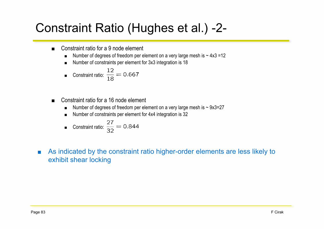
■ Constraint ratio for a 9 node element■ Number of degrees of freedom per element on a very large mesh is ~ 4x3 =12■ Number of constraints per element for 3x3 integration is 18
■ Constraint ratio:
■ Constraint ratio for a 16 node element■ Number of degrees of freedom per element on a very large mesh is ~ 9x3=27■ Number of constraints per element for 4x4 integration is 32
■ Constraint ratio:
■ As indicated by the constraint ratio higher-order elements are less likely toexhibit shear locking
Constraint Ratio (Hughes et al.) -2-
F CirakPage 84
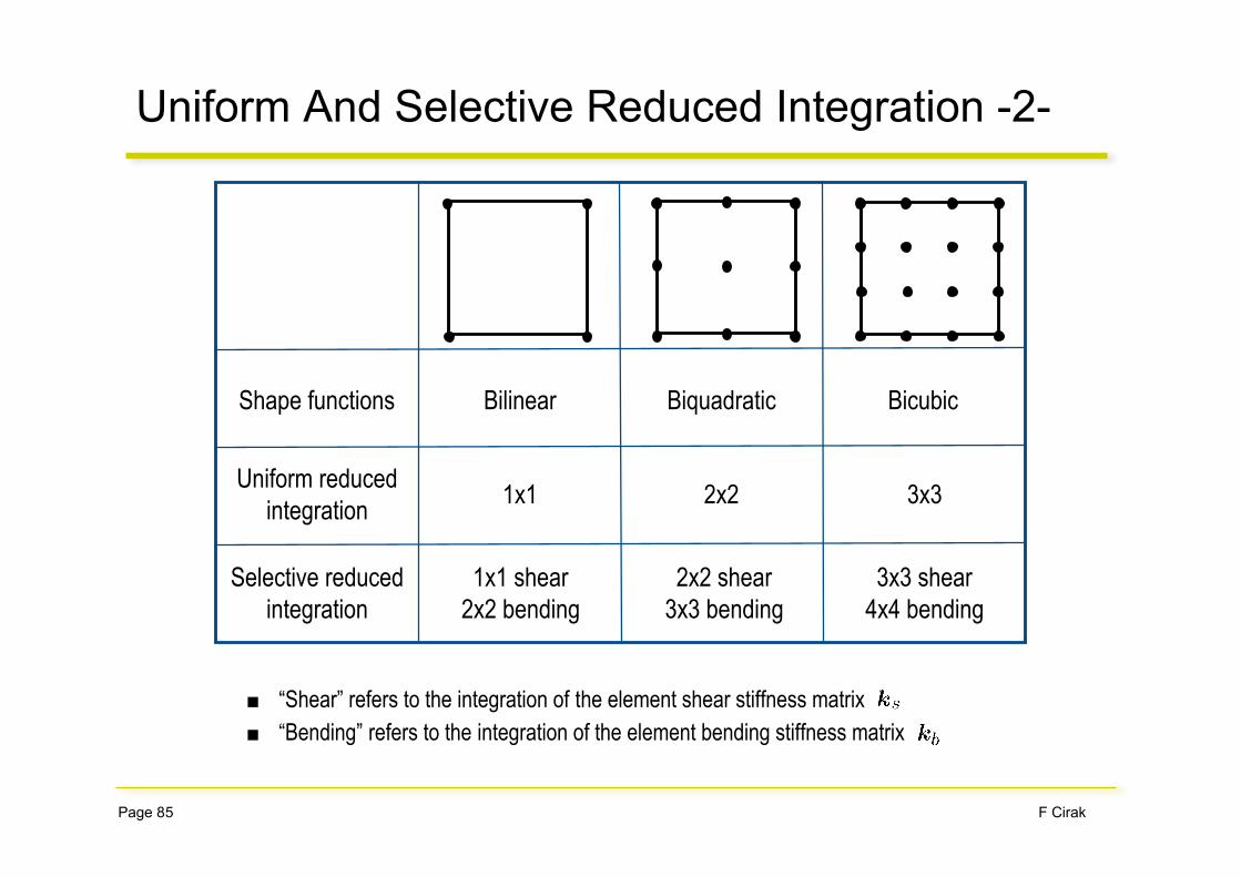
Uniform And Selective Reduced Integration -1-
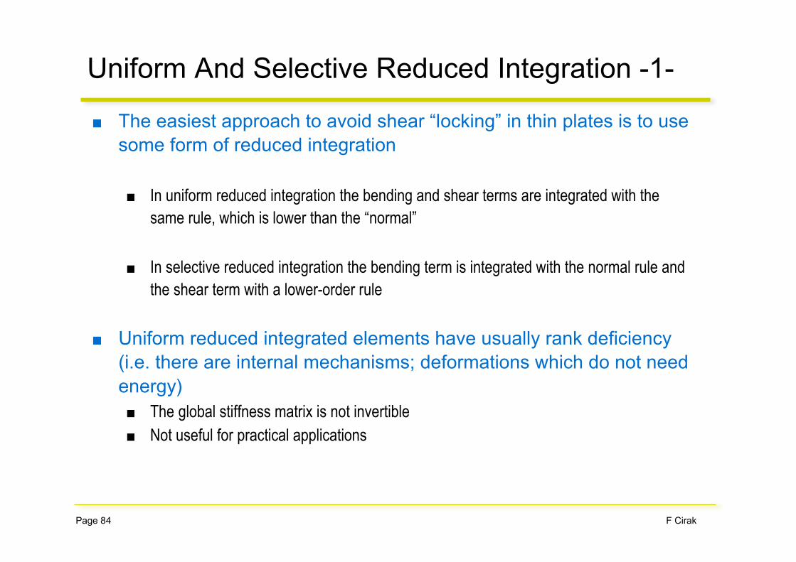
■ The easiest approach to avoid shear “locking” in thin plates is to usesome form of reduced integration
■ In uniform reduced integration the bending and shear terms are integrated with thesame rule, which is lower than the “normal”
■ In selective reduced integration the bending term is integrated with the normal rule andthe shear term with a lower-order rule
■ Uniform reduced integrated elements have usually rank deficiency(i.e. there are internal mechanisms; deformations which do not needenergy)■ The global stiffness matrix is not invertible■ Not useful for practical applications
F CirakPage 85
Uniform And Selective Reduced Integration -2-
■ “Shear” refers to the integration of the element shear stiffness matrix■ “Bending” refers to the integration of the element bending stiffness matrix
BicubicShape functions
Selective reducedintegration
Bilinear
1x1
Biquadratic
2x2 3x3Uniform reduced
integration
1x1 shear2x2 bending
2x2 shear3x3 bending
3x3 shear4x4 bending

F CirakPage 86
Discrete Kirchhoff Elements
■ The principal approach is best illustrated with a Timoshenko beam
■ The displacements and rotations are approximated with quadratic shapefunctions
■ The inner variables are eliminated by enforcing zero shear stress at the twogauss points
■ Back inserting into the interpolation equations leads to a beamelement with 4 nodal parameters

F CirakPage 87
Assumed Strain Elements
■ It is assumed that the out-of-plane shear strains at edge centres are of“higher quality” (similar to the midpoint of a beam)
■ First, the shear angle at the edge centresis computed using the displacement and rotation nodal values
■ Subsequently, the shear angles from the edge centres are interpolated back
■ Note that the shape functions are special edge shape functions
■ These reinterpolated shear angles are introduced into the weak form and are for element stiffnessmatrix computation used


![[S Timoshenko] Theory of Plates and Shells (McGraw(BookFi.org)](https://img.dokumen.tips/doc/110x75/5695d3de1a28ab9b029f7999/s-timoshenko-theory-of-plates-and-shells-mcgrawbookfiorg-56afcc0fc5152.jpg)