Embed Size (px)
Citation preview

Scanned by CamScanner
EXPERIMENT - 1
VALVE TIMING DIAGRAM OF FOUR STOKE DIESELENGINE
To draw the valve timing diagram of” the given four stroke cycle diesel engine.
Apparatus Required:
1. Four stroke cycle diesel engine
2.. Measuring tape
3. Piece of paper
Theory
The diagram which shows the position of cmnk of four stroke cycle engine at the beginning and at the end of suction, compression. expansion, and exhaust of the engine are called a.s Valve Timing Diagram.
Thc extreme position of the bultom of the cylinder is called “Bottom Dead Centre”
[BDC].IN the cnse of horizontal engine, this is known os “Outer Dend Centre” [ODC]. The position of the piston at the top of they cylinder is called “Top Dead Centre” [TDC].ln case of horizontal engine this is known as “Inner Dead Centre” [TDC]. In case of horizontal
engine this is known as “inner dead cenire“[IDC]
In an ideal engine. the inlet valve opens at TDD and closes at BDC. The exhaust valve
opens at BDC and closes at TDC. The fuel is injected into the cylinder when the piston is at
TDC and at the end of compression stroke but in actual prartise it willdiffer.
Inlet velve opening end closing:
In an actual engine. the inlet valve begins to open 10°C to 20 °C before the piston rvttch«s the
TDC during the end uf exhaust stroke. This is ensure that the valve will & fully upen when the piston
reuchus tho TDC.
Exhaust valve opening and closlng
Complete clearing of the burned guses from the cylinder is necessiiry to take in more air into
the cylinder. To achieve this exhaust valve is opens at 35° to 45° before BDC and closc•s at 10° to 20°
after the TKC. It is cluur from the diagram, for rertoin period both inlet valve and exhaust valve
remains in open condition. The crank angles for which the both

Scanned by CamScanner
t .d - Nzpiari•lon 1 .end I Jtñn ! fit1”
plc - F-.x1jaust ' II •‹c \Itun I M*"
Observation andTabulation
S.No. Evonl Positionolcrnnx Dislsncein Angus
w.r.to MDCoi BOC t indegrees
Before TDC

Scanned by CamScanner
Fuel valve openlng and closing:
The fuel valve opens at 10° to before TDC and closes at 11° to 20 ° after TDC.
I. Remove the cylinder head cover and identify the inlet valve. exhaust valve and piston
ofparticular cylinder.
Mark the BDC and TDC position of flywheel
This is dnne by Rotating the crank in usunl direction of mention and observe ihe position
of the fly wheel, when ihc• pision is moving downwards tit which ihe piston begins to
m‹ive in oppositc direction. i.e. finn down to upward direction. Mot.e the mork un the
flywheel with reference io fixed point on the body of the engine. That pnint i.s the BDC
for thnt cylinder .Measure the circumference. Then point is TDC and is dinmetricnlly
opposite to theBOC.
3. lnsen thr piiper in the *ppet clearance uf buth inlet anti exhaust valves
4. Slowly rotote the crank until the paper in the tuppet clearence of inlet valve is gripped
.make the mitrk un fly wheel against fixed reference. This position represmt the inlet
valve open ( VO). Measure the distance frorrt TDC and tiibulate the distance.
5. Rotate the crank further. till the piiper is just free to move. Make the marking on the
flywheel against the fixed reference. This position represents the inlet x alve close (IVC).
Measure the distance frnm BDC imd labulalo the distance. Rotate the crnnk further, till
the pnper in the tnppet clearnnce of exhaust vaI ve is gripped. Make the marking on the
flywheel again.st rixed reference. This position represents the exh‘ausi valve open tEVD).
Measure the distance rrom BDC tindtabulate.
6. Then converted the measured distances angle in degrees
Result:
The vale c timing diagram for the given four struke Diesel engine was drawn.

Scanned by CamScanner
EXPERIMENT NO.- 2
STUDY OF STEAM BOILERS
AIM : To study the working of various types of steam boilers
Introduction
A steam boiler is a closed vessel which boiler generator steam by transferring heat
produced by burning of fuel to water, The steam boiler produced is used for power generation
or process heating.
Selection of steam generstom:
1. The power required & working pressure.
2. The fuel & wateravailable.
3. The probable loiidfactor.
Classification of Boilers:
The steam boilers are classified according to the following basic:
1. Flow of water & healpases a. Fire tubeboiler
b. Water Tubeboiler
.3. Metho‹i of water circulation
a. Natural circulation
b. Forced circulation
4. Pressure developed
a. Low pressure boi!er
b. High pressure boiler
Scanned by CamScanner
3
10
i ty
I I
2

Scanned by CamScanner
5. Nature of service
c Satationary boiler
b. Mobile boiler
Pressure Bollers:
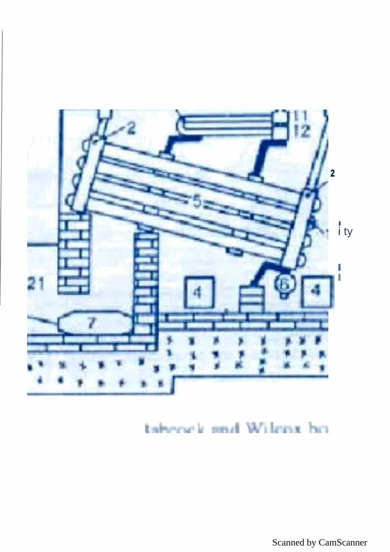
Modem high pressure boilers generate steam at a pressure itiore than 75 bar. Example: Bubcock & Wilcom boiler, Lamont bniler. BHEL boiler.
BHELL BOILERS:
consists of feed pump, a economizer a boiler drum. radiant & connective super hearers. FD fan. air pre heaters 1 & * .Electro static prectpitator 1 D fan & chimney.
The feed water from the hot well is pumped with the help of a feed pump to boiler from the through
economy .In boiler drawn Idle fed water is circulated to number of valves in furnaces with is burnt. The
feed water is evaporated into wet stecm md the wet steam flows beck to boiler dmwn.

Scanned by CamScanner

Scanned by CamScanner

Scanned by CamScanner
EXPERIMENT NO. - 3

Scanned by CamScanner

Scanned by CamScanner
SUCTION STROKE :With the movement of the piston from T.DC. to BDC
during this stroke, the inlet valve opens and the air at atmospheric pressure is
drawn in side the engine cylinder; the exhaust valve However remains
closed.This operation is represented by the line5-1
COMPRESSION STROKE: The air drawn at atmospheric pressure during the
suction stroke is compressed to high pressure and temperature to the piston
moves from B.D.C. to T.D.C. Both the inlet and exhaust valves do not open during
any part of this stroke.This operation is represented by1-2
POWERSTROKE:AsthepistonstartsmovingfromT.D.C to BD.C, the quantity of fuel is
injected into the hot compressed air in fine spray 5 by the fuel inject Drand it (fuel
starts burning at constant pressures how by the line2-3.
At the point fuel supply is cut off.The fuel is injected at the end of compression
stroke but in actual practice the ignition of the fuel starts before the end of
the compression stroke. The not gases of the cylinder expand adiabatically to
point 4. Thus doing work on the piston.
EXHAUST STROKE: The piston moves from the B D.C. to T.D.C. and the exhaust
gases escape to the atmosphere through the exhaust valve. When the
piston reaches the T.D.C. the exhaust valve closes and the cycle is completed.
This stroke is represented by the line1-5.

Scanned by CamScanner

Scanned by CamScanner
EXPERIMENT NO. - 4

Scanned by CamScanner

Scanned by CamScanner

Scanned by CamScanner
Experiment No. - 5
Objective: to study different boiler mountings and accessories
Introduction The various boJler mountings and accessories that are used in steam boilers are water level indicator, pressure gauge, safety vaives. stop valve: blow off Valve, feed check valve, fusible plug, air pre-heater, super heater, economised and feed pump. The boiler mounting and accessories are used in steom boilers for its proper, efficient and satisfactory working. In this article, we will discuss the functions of each ofthem.
Boiler Mountings Boiler mountings are equipments those essentially required to operate the boiler i.e. without
those boiler would not be operative. Following are the equipments installed on the boilers for
successful operation.
1. Water Level Indicator
It is fitted in front of the boiler rind generally present two in number. It is used to indicate the
water level inside the boiler. It shows the instantaneous level of water that is present inside the
steam boiler which is necessary for its proper working.

Scanned by CamScanner
Figure 2: Water level indicator
?. Pressuregauge
It is also present in front of the boiler. lt is used to measure the pressure of the steam inside the
boiler. The pressure gauges generally used are of BOufden iype.
Figure 3: Bourdon tube pressure gauge
3. SafetyValves
Safety valves are attached to the steam boiler chest. It is used to prevent explosion due to
excessive internal pressure. When the internal pressure inside the boiler exceeds its working
pressures than the safety valves blow off the steam and maintains the internal pressure. Generally
two safety valves are present on aboiler.

Scanned by CamScanner
' 17/35 _
Figure : Steam Safety Valves
4. Stop Valve (steam stopvalve)
It is usually fitted on the highest part nf the boiler with the help of a fiange. The m in fi action o°
ae stop valve is (i) to control the now of steam from the boiler to the mai completely shut off the steam supply when required.
5. Blow Off Valve
It is fitted at the bottom of the boiler drum. The functions of blow-off Valve is (i) to empty the
boiler whenever required. (ii) to discharge the scale, mud and sediments which gets collected at
the bottom of theboiler.
Scanned by CamScanner
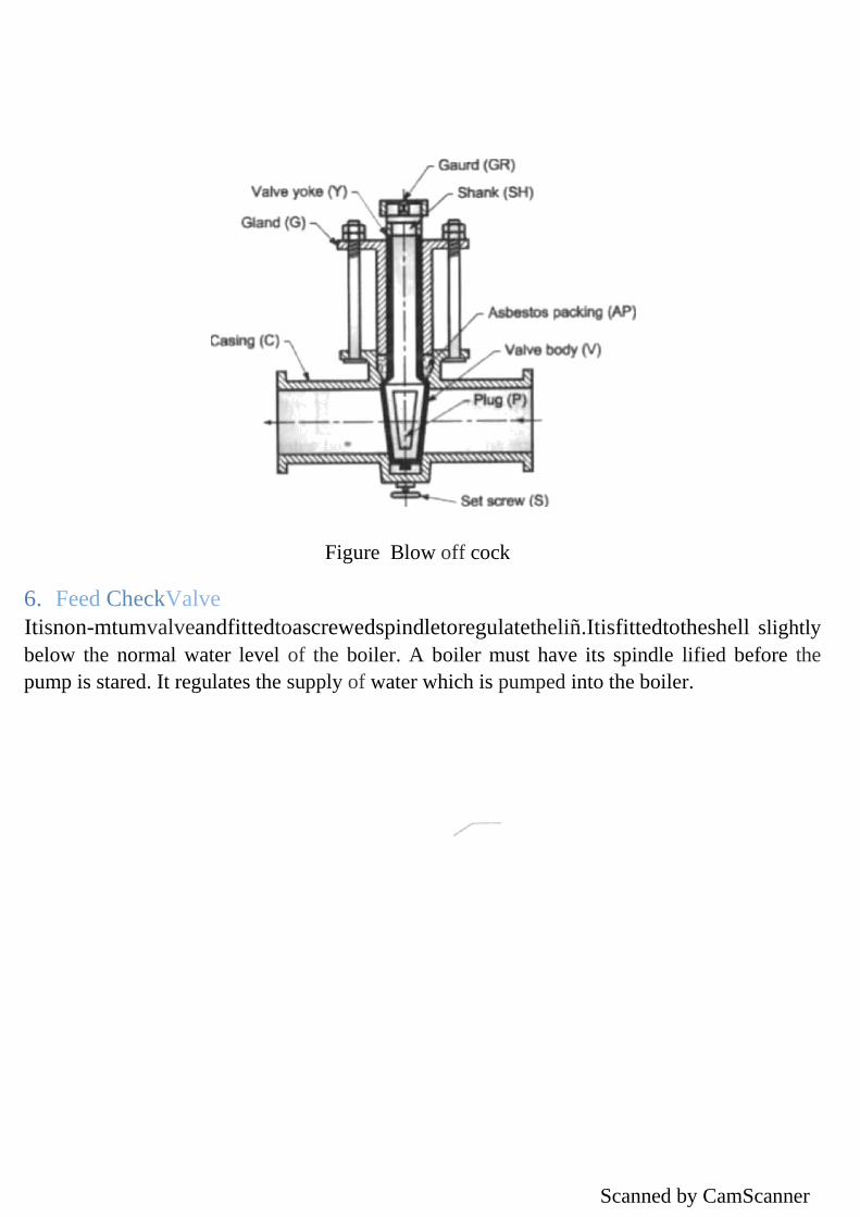
6. Feed CheckValve
Figure Blow off cock
Itisnon-mtumvalveandfittedtoascrewedspindletoregulatetheliñ.Itisfittedtotheshell slightly
below the normal water level of the boiler. A boiler must have its spindle lified before the
pump is stared. It regulates the supply of water which is pumped into the boiler.

Scanned by CamScanner
7. FusiblePlug
It is fitted to the crown plate of the furnace or firebox. Its function is to extinguish fire in the
fumncewhen thewaterlevelintheboilerfallstoanunsafelimii.Thisavoids theexplosionthat may
take place because of the overheating of the furnaceplate.
19/35
Figure Fusible Plug
Boiler accessories
Boiler accessories nre the integrnl parts of the boiler. They are used in the boiler to improve its
effiriency. However, without these a boiler can be operative but performance would be improved
with these.
1. Airpreheater
It is used to recover heat loom the exhaust gases, It is installed between the econorniser and
the chimney.

Scanned by CamScanner
Figure Air preheater
2. Superheater
It is placed in the path of hot flue gases from the furnace. A superheater is an importar
accessory used in the boiler. Its main function is to increase the temperature of saturated stean
without raising its pressure.
3. Economiser
Figure Superhenter
It is used to heat the feedwater by the utilization of heat from the hot fuel gases before it leave
the chimney. An economised improves the economy of the steam boilers.
FlueGasin
HotCIFOUt
FreshemIn
FlueGastoStack

Scanned by CamScanner
Scanned by CamScanner
To
facilitate straight ahead recovery after completing aturn. 7. To absorb road shocks thus preventing them to get transmitted io the hands of thedriver.
8. To swing the wheels to the left orrighi.
To achieve correct steering, iwo lypes of steering mechanisms are used.
i) Davis SteeringMechanism
iil Ackermann SteeringMechanism
The main difference between these two is thai the Davis mechani.sm has sliding pairs, whereas
the Ackermann mechanism has only turning pairs. The sliding pair has more friction than the
turning pair and hence Davis mechanism will wear our after certain time. Therefore Ackermann
mechani.sm is preferred to the Onvis mechanism.
Ackemiann Principle: ln order io achieve the instantaneous centre, the inner wheel must turn
through a greater angle than the ouier. This difference in movement of the inner and outer wheels
is obtained by inclining the links KA and LB. The effect of this will be clear from fig. lf ihe track
red AB moves, say through x distance, measured pamllel io the axle beam, link KA will move
through a greater angle than link LB. The inclination of these links is such that lines drawn
through their will intersect theoretically at the centre line of the car. This arrangement is known
as Ackermann principle or linkage and can also be applied if the track rod is placed in front of
theaxle.
Scanned by CamScanner
27/44
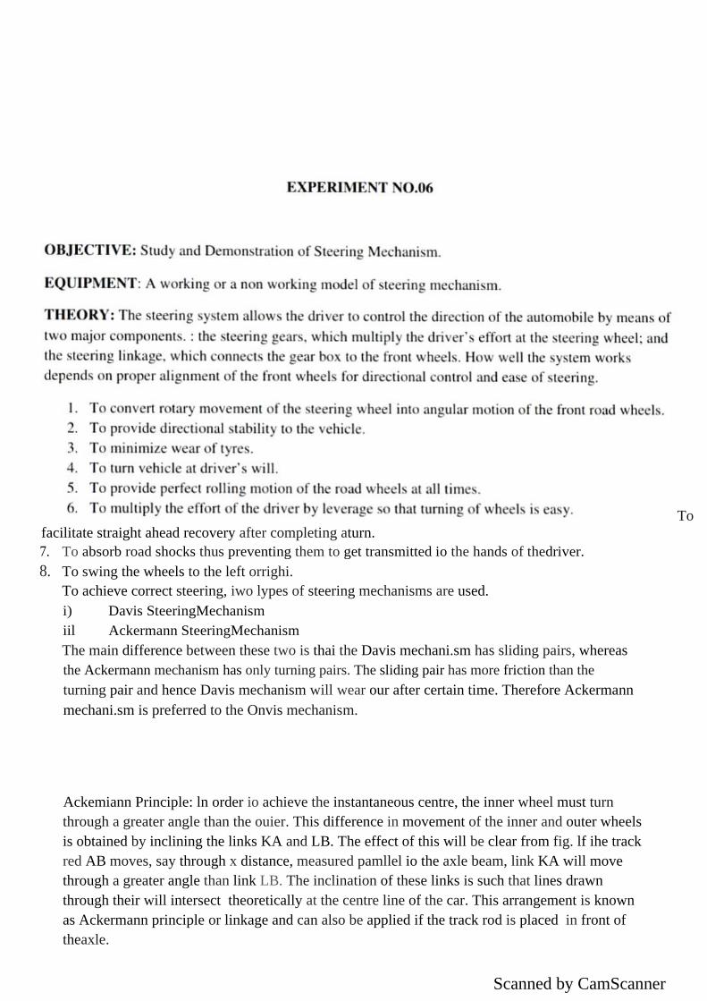
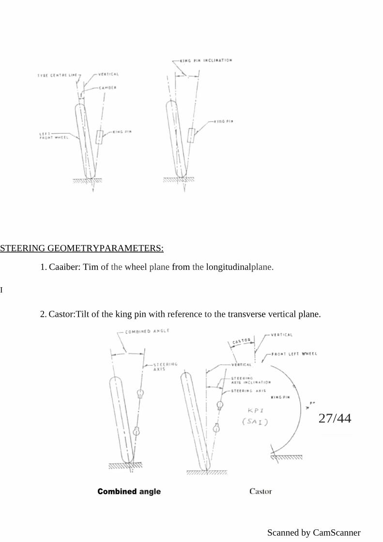
STEERING GEOMETRYPARAMETERS:
1. Caaiber: Tim of the wheel plane from the longitudinalplane.
I
2. Castor:Tilt of the king pin with reference to the transverse vertical plane.
Combined angle

Scanned by CamScanner
3. King pin Inclination: King Pin inclination is the tilt of the king pin from the longitudinal
vertical.

Scanned by CamScanner
Toe in Toe out : It is the amount by which the from wheels are set close ring ether at the front at the rear when the vehicle is stationary.
On the other hand, the wheel may be set closer at the rear than at the front in which case is he difference
of the distances between the front wheels at the front and at the rear is called toe out.
The steering genr converts the rotary motion of the steering wheel into suaight line motion of the
linkage. There are two basic types of steering gears, the pitman-arm type and the rack and pinion type.
Either type can be used in a manual steering system or a power strering system. The pilman type has a
gear bux at the lower end of the steering shaft. The mck and pinion type has a small gear (a pinion) at
the lower end of the steering shaft. The action is the same in either sysiem. When the steering wheel and
shoft are turned by the driver, the rotary motion is changed into straight line motion. This causes the
fronl wheels to pivot or xwing from one side to the other In steer thecar.
Onejobofthesteeringgearistoprovidemechanical advantage.Inamachineor
is the ratio of the output force to the input force applied to it. This means that a relatively small applied
force can produce a much greater force at the other end of the device.
1. Worm andWheel
2. Cam and DoubleRoller
3. Worm andNut
4. Recirculating Balltype
5. Rack andPinion
Scanned by CamScanner
EXPERIMENT NO. - 7 Aim: To scudy various braking system and their components used in Automobile.
REQUIREMENTS Brakes, ingeneral, are required to slow,stop or hold the vehicle and convert the kinetic energy of motion into heat and then to dissipate this heat
I. Application of brakes should bring the vehicle to a relatively quick stop on any type of
road-wet, even, un even, uphill or downhill.
The vehicle may be at any speed, laden or unladen.
2. A separate mechanical brake is required to hold the vehicle in position on agradient
3. The braking system components must require minimummaintenance.
4. The pedal ellon required to produce maximum deceleration should be negligible and
should not vary with the condition of theroad.
5. The braking system should allow minimum time between application of pedal effortand
actual braking effect on the drums.
6. The braking action should not involve any noise, or drih the vehicle away from itsdesired
path.
7. Provisions for quick heat dissipation must beincorporated.
8. Asecondarybrakingsystemmustbeincorporated,shouldtheprimarybrakingsystemfail.
Classification Broadly, brakes are classiRed as (ij drum brakes and (ii) disc brakes. The operating systems for such brakes can be of many types:
Mechanical, hydraulic, pneumatic, vacuum, electrical,@ combinedvacuum and hydraulic.
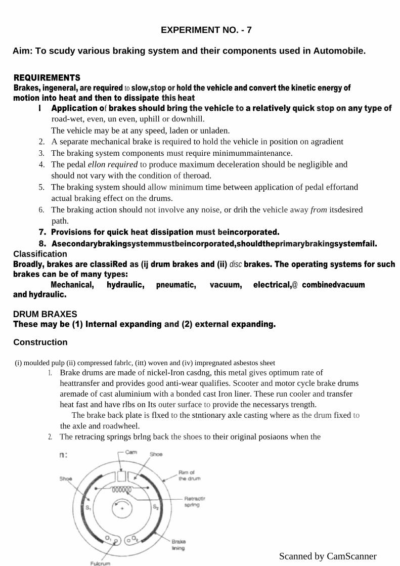
DRUM BRAXES These may be (1) Internal expanding and (2) external expanding. Construction
(i) moulded pulp (ii) compressed fabrlc, (itt) woven and (iv) impregnated asbestos sheet
1. Brake drums are made of nickel-Iron casdng, this metal gives optimum rate of
heattransfer and provides good anti-wear qualifies. Scooter and motor cycle brake drums
aremade of cast aluminium with a bonded cast Iron liner. These run cooler and transfer
heat fast and have rlbs on Its outer surface to provide the necessarys trength.
The brake back plate is flxed to the stntionary axle casting where as the drum fixed to
the axle and roadwheel.
2. The retracing springs brlng back the shoes to their original posiaons when the

Scanned by CamScanner
brakepedal isreleased.
Disc Brabes
Figure shows the construction and working of a disc brake.It consists of
thefollowingparts:Connectingtube Cylinder @Piston Frictionpad Hydraulicfluid @Brakedisc @ master cylinder @Calliper
Disc It is made of high-grade of grey cast iron having pearlitic structure to give better wear resistance property. The surface finish of the disc should be smooth with a runout not more than 0.10 mm or else vibrations would occur at the pedal. This disc which rotates with the car wheel is efficiently cooled as most of its area lies exposed. Ventilated discs have two discs linked by internal ribbings Instead of one thick dlsc. Air can flow through ventilations from all dlrectlons to make cooling faster. Calipers These are of V-shaped type and are tn two halves. Each half has a pad bonded to a steel plate, a steel plston and a brake cyllndrlcal houslng bolted together. Both these halves are hydraulically linked so that equal pressure may be applied on the pad through floating pistons. Hydraulic pressure is applied only on one side of the ptston. Nipples are provided with callpers for bleeding purposes. Somedmes 4-piston campers are used ror effective braking.
When the driver applies pressure on the brake pedal, hydraulic pressure pushes the pistons out from their housing. The pistons, in turn, press the brake pads against the moving disc faces, causing frictlonandhenceslowingItdown.Hydraulicpressure1sequallyapplied bythehydraulicfluidtothe floating pistons on either slde. When the driver takes his foot off the brake pedal, hydraulic pressure on the friction pads is released, the pistons move Inwards and break their contact with thedlsc. Advantages of disc brakes over Drum Brakes:

Scanned by CamScanner
1. Disc brakes provide better stability since these have uniform pressure distribution over
the pads than that of the brake linings in the case or drum brakes.
2. Increasedtemperaturedoesnotaffectthediscpadsmuchcomparedtothebrakeliningsofthe
drumbrakes,
3. The design of the brake adjusters becomes simple because when hot. the discs expand
towards the pads causing no loss in pedaltravel
4. The application of brakes causes lesser bearing load since the overhang is !esser over the
adjacentbearing
S. Maintenance and repairs of disc brakes iseasy
Disadvantages
1. Disc brake assemblies are costlier than drumbrakes
2. The pads wear off fast compared to brake shoe linings of drum brakes. Disc brakes
havehigher brakepressures
3. Complete protection to the disc from road debris is provided wlth greatdifficulty
4. The high temperature operation of disc brakes causes evaporation of the brake fluid and
detefior.ation ofseals
S. In the case of cars fitted with disc brakes, an external servo mechanism is required
because these have no self energising effect. Such an arrangement is not required in cars
having drumbrakes
6. Handbrakes ca o be installed on drum brakes because these have self energizing effect.
Disc brakes offer difficulty in installing handbrakes.
MECHANICAL BRAKES
Mechanical brakes have been outdated in cars but are mostly used as 'parking brakes‘. Scooters, motor cycles and mopeds use such type of brakes.
Mechanical brakes are simply drum brakes consisting of (i) brake drum, and (ii) brakeshoes
with brake linings-there are two shoes called leading and trailing, (iii) cam or toggle lever, (iv) retractorspring,(v)abrakeleverforthedriver(awireorrodconnectsthislevertothecam)and (vi) brake backplate.
The leading shoe is the first shoe after the cam in the direction of rotation. The friction between the shoe and the drum pushes the tip of the leading shoe harder in contact with the drum and pushes it off at its toe, whereas the trailing shoe tip is thrown away off the hrake dru m, as the drum rotates againstit.
The braking effort by the leading shoe is four times that of the trailing shoe and hence it rears faster. The leading shoe has a self-applying effect called the ‘self-servo effect'. HYDRAULIC BRAKES
These types of brakes consist of master cylinder, which contains hydraulic brake fiuid.
Mastercylinderisoperatedbythebral‹epedaland isfurtherconnectedtothewheelcylinderineach wheel through pipelines, unions and flexible lines. The system is so designed that even when the brakes are in the released position, a small pressure of about 50kpa is maintained in the pipelines to ensure that the cups of the wheel cylinder are kept expanded. This prevents the air entering the wheel cylinders when the brakes are released. Besides this pressure also serves the following purposes: 1. It keeps the rree travel of the pedal minimum by opposing the brake shoe retractionsprings. 2. Duringbleeding,itdoesnotallowthefluidpumpedintothelinetoreturn,thusquicklypurgingair from thesystem.
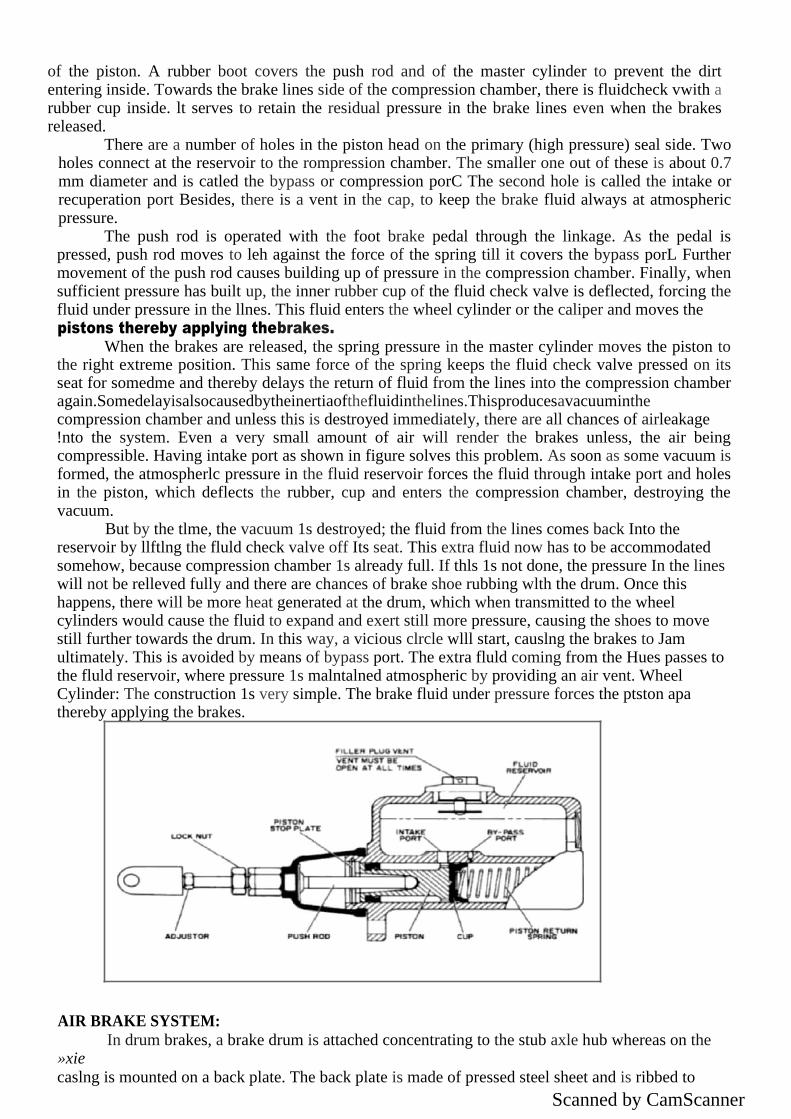
MASTER CYLINDER: It consists of huid reservoir and compression chamber in which piston operates. The fluid in
the reservoir compensates for any change in the fluid volume in the pipelines due to temperature variations and to some extent due to leakage. To prevent leakage there are rubber seals on both sides of the piston in the compression chamber. The fluid always surrounds the reduced diameter region
Scanned by CamScanner
of the piston. A rubber boot covers the push rod and of the master cylinder to prevent the dirt entering inside. Towards the brake lines side of the compression chamber, there is fluidcheck vwith a rubber cup inside. lt serves to retain the residual pressure in the brake lines even when the brakes released.
There are a number of holes in the piston head on the primary (high pressure) seal side. Two holes connect at the reservoir to the rompression chamber. The smaller one out of these is about 0.7 mm diameter and is catled the bypass or compression porC The second hole is called the intake or recuperation port Besides, there is a vent in the cap, to keep the brake fluid always at atmospheric pressure.
The push rod is operated with the foot brake pedal through the linkage. As the pedal is pressed, push rod moves to leh against the force of the spring till it covers the bypass porL Further movement of the push rod causes building up of pressure in the compression chamber. Finally, when sufficient pressure has built up, the inner rubber cup of the fluid check valve is deflected, forcing the fluid under pressure in the llnes. This fluid enters the wheel cylinder or the caliper and moves the pistons thereby applying thebrakes.
When the brakes are released, the spring pressure in the master cylinder moves the piston to the right extreme position. This same force of the spring keeps the fluid check valve pressed on its seat for somedme and thereby delays the return of fluid from the lines into the compression chamber again.Somedelayisalsocausedbytheinertiaofthefluidinthelines.Thisproducesavacuuminthe compression chamber and unless this is destroyed immediately, there are all chances of airleakage !nto the system. Even a very small amount of air will render the brakes unless, the air being compressible. Having intake port as shown in figure solves this problem. As soon as some vacuum is formed, the atmospherlc pressure in the fluid reservoir forces the fluid through intake port and holes in the piston, which deflects the rubber, cup and enters the compression chamber, destroying the vacuum.
But by the tlme, the vacuum 1s destroyed; the fluid from the lines comes back Into the reservoir by llftlng the fluld check valve off Its seat. This extra fluid now has to be accommodated somehow, because compression chamber 1s already full. If thls 1s not done, the pressure In the lines will not be relleved fully and there are chances of brake shoe rubbing wlth the drum. Once this happens, there will be more heat generated at the drum, which when transmitted to the wheel cylinders would cause the fluid to expand and exert still more pressure, causing the shoes to move still further towards the drum. In this way, a vicious clrcle wlll start, causlng the brakes to Jam ultimately. This is avoided by means of bypass port. The extra fluld coming from the Hues passes to the fluld reservoir, where pressure 1s malntalned atmospheric by providing an air vent. Wheel Cylinder: The construction 1s very simple. The brake fluid under pressure forces the ptston apa thereby applying the brakes.
AIR BRAKE SYSTEM:
In drum brakes, a brake drum is attached concentrating to the stub axle hub whereas on the »xie caslng is mounted on a back plate. The back plate is made of pressed steel sheet and is ribbed to

Scanned by CamScanner
increase rigidity and to provide support for the expander, anchor and brake shoes.lt also protects the dmm and shoe assembly from mud and dust Moreover, it absorbs the complete torque reaction of the shoes due to which reason it is sometimes also called torque plate. Two brake shoes are anchored on the back plate. One or two retractor springs are used which serve to keep the brake shoes away from the drum when the brakes are not applied The brake shoes are anchored atone
Brake Lines and Hoses
The connections between the master cylinder and whee! cylinders are made of copper coated, tin plated, annealed, steel tubings and flexible hoses. A flexible hoses is made up of alternate layers of rubber and fabric sheets wound over each other. These are used to connect the steering front wheels. Working of Hydraulic Brahes 8rakes Pressed on When the dfiver applies force on the brake pedal, the master cylinder piston moves forward, closing the fluid supply rrom the reservoir. The fluid is compressed and force is transmitted equally to the brake shoes through the wheel cylinder pistons. The wheel cylinder pistons move outwards and allow contact between the brakedrum and brakeshoes. Brakes Released
Thefluid slowly returns from the wheel cylinder into the master cylinder by opening the check valve. The spring now closes the check valve, The slow return of the fluid causes vacuum in the compression chamber. Fluid in the reservoir being at atmospheric pressure, flows to the compressionchamberthroughthefeedholes.Meanwhile,withthedestruction of vacuum, more fluid

Scanned by CamScanner
EXPERIMENT NO. - 8
AIM: To study different Layout ofAutomobile. INTRODUCTION
Automobile is a self-propagafing vehicle which transmits motion.Present age is called age of automobile. Vehicle producing power within itself for its propulsion is self-propelled vehicle.eg. nioped,scooter,motorcycle, etc.Germany 1s the birthplace of automobile.The first
automobile powered by steam engine was built in France by Nicholas joseph caugnot in 1769. lt was three-wheel vehicle with speed 2.5 miles per hour.
1) FRONT AXLE WHEEL DRIVE
In this drive the engine is mounted on the front side i.e. front engine unit drives a beam type rear wheel supported on leaf springs through a propeller shaft with twD universal joints. Coil springs, the front wheels are independently sprung. This is one of the oldest
layout. ADVANTAGES
a] balanced weight distribution. b]easyfrontwheelsteeringmovement. c)large luggage space provided at rear. d) maintenance is easy.
DISADVANTAGES a] long propeller shaft
b1 more noise, wear is more
1 4
2) REAR AXLE DRIVE
The propeller shaft is eliminated. The clutch engine gearbox drive with the single unit. engine is at the rear end. Power is completely transmitted to the rear wheel. there is no adjustment in propeller shaft

Scanned by CamScanner
ADVANTAGE
a] excellent tr.action is available while clink bing the wheel.
b] larger passenger space is available
c]compact,accessible power‘, d] avoid not.se.
3) FRONT ENGINE FRONT WHEEL DRIVE
1. 1 provides optimum passenger space . propeller shaft length is retluced . good grip to
road surface due to englne weight at front .The chance of skidding is reduced . natural air cooling of radiator . power for cooling is red freed.
ADVANTAGES
a] no need to decrease interlnr space for driven .shaft. bJcostisless
c] low weight, means better mileage
.d] lmJi roves drlve train as.senihly .
cj b»ttci cross wind assclTlbly.
DISADVANTAGES
a] limirs the acc of the of front wheel rlrive vehicle.
b] in less traction condltions front drive wheel loose tractlOn first maklng seeing
ineffective, c] Ccnti e of gi avlty of vehicle is forwai d.
4) FOUR WHEELDRIVE
All foti r wheels are tlriven lay engine making entire weight an ilalale for tractitin .these
ai c ver y useful on mill station if onc of thc wheel s kidding tlivn other wheel traiisiriii the tractive l’orce to the vehicle . "the steering of’ lotir wheel drive is liar d .when front wheel fall
into ditch they can be driven ont higher initlJl end running cost because of extra fuel
consumption .used iiijeep ,military vehicles .

Scanned by CamScanner

Scanned by CamScanner
EXPERIMENT NO. - 9
AIM: To study construction and working of Clutches .
lTRODUCTlON The motion of the crankshaft is transmitted through the clutch the gear box or transmission,
which consists or set of gears to change the speed. From gear box, the motion is transmitted to the
propeller shaft through the universal joint and then to the differential through another universal joint. Universal joint is used where the two rotating shahs are connected at an angle for power transmission. Finally the power is transmitted to the rear wheels through the rear axles. The differentialprovidestherelativemotiontothetworearwheelswhilethevehicletakingaturn.Thus, the
power developed inside the cylinder is transmitted to the rear wheels through a system o( transmission.
The vehicles which have front wheel drives in addition to the rear wheel drives include a
second set or propeller shafts, universal joints, final drives and differentials for the frontunits. CLUTCH AND ITS FUNCTlON
Clutch is a device used in the transmission system of motor vehicle to engage and disengage the
engine to transmission. Thus the clutch is located between the engine and the transmission. When the
clutch is engaged, the power flows from the engine to the rear wheels through the transmission system
and the vehicle moves. When the clutch is disengaged, the power is not transmitted to the rear wheels
and the vehicle stops while the engine steel running, when shifting the
gears,whenstoppingthevehicleandidlingtheengine.Theclutchisengagedonlywhenthevehicleis to
move and is kept engaged when the vehicle is moving. The clutch also permits the gradual taking up of
the load. When properly operated, it prevents jerky motion of the vehicle and thus avoids putting
undue strain on the remaining parts of the power transmissionsystem. REQUIREMENTS OF CLUTCH
1. Torque transasission. The clutch should be able to transmit maximum torque of theengine. 2. Gradual engagement The clutch should engage gradually to avoid suddenjerks.
3. heat dissipation .The clutch should be able to dissipate large amount of heat whichis
generated during clutch operation due to friction.
4. Dynamic balancing. The clutch should be dynamically balanced. This is particularly
required in the case of high speed engineclutches. 5. Vibration damping. The clutch should have suitable mechanism to damp vibrations andto
eliminate noise produced during the power transmission.
6. Size. The clutch should be as small as possible in size so that it will occupy minimum space. 7.Free pedal play. The clutch should have free pedal play in order to reduceeffective
clamping load on the carbon trust bearing and wear on it.
8. Easy in operation. The clutch should be easy to operate re9 uiring as little exertion aspossible on the part of thedriver.
9. Lightness. The dnven member of the clutch should be made as light as possible so that it will notcontinue to rotate for any length of time after the clutch has been disengaged,
TYPES OF CLUTCHES
a, Single plate clutch b. Multiplate clutch
cronec|u[ch.
2. Centrifugalclutch. 3. Semi-centrifugalclutch.
4. Conical spring clutch or Diaphram clutch: S..Electro-magnetic clutch.
6.Vaccum clutch.
A) SINGLG PLATECLUTCH
lt is most common type of clutch used in motor vehicles. Basically, it consists of only one
clutch plate, mounted on splines of the clutch shaR, as shown in fig. The flywheel is mounted on the
engine crankshah and rotates with it. The pressure plate is bolted to the flywheel through clutch
springs, and is free to slide on the clutch shaR when the clutch pedal is operated. When the clutchis

Scanned by CamScanner

Scanned by CamScanner
engaged, the clutch plate is gripped between the flywheel and the pressure plate. The friction linings
are on both the sides of the clutch plate. Due to the friction between the flywheel, clutch plate and
pressure plate, the clutch plate revolves wlth the flywheeL As the clutch plate revolves,the clutch shaft also revolves. Clutch shait is connected to the transmission. Thus, the engine poweris transmitted to the crankshaft to the clutch shaft.
When the clutch pedal is pressed, the pressure platemoves back against the force of the springs, and the clutch plate becomes free between the flywheel and the pressure plate. Thus, the
hywheels remain rotating as long as the engine is running and the clutch shaft speed and finally it stops rotating As soon as the clutcb pedal is pressed, the clutch disengaged; otherwise it remains engaged due to the spring forces.
reducessolely is said tothe
B) CENTRIFUGAL CLUTH The centrifugal clutch uses centrifugal forces, instead of spring force. Also, it does not require
clutch pedal for operating the clutch. The clutch is operates automatically depending upon the engine speed. The vehicle can be stopped in gear withoutstalling
theengine. Similarly, the vehicle can be stared in any gear by passing the accelerator pedal.
Fig shoes a centrifugal clutch. It consists of weights A pivoted at B. When the engine speed
increases the weights fly off due to the centrifugal force, operating the bell crack levers, which press the plate C. The movement of the plate C presses the spring E, which ultimately presses the clutch plate D on the flywheel against the spring G. this makes the clutch engaged. The spring G keeps the
clutch disengaged at low speeds at about 500 rpm. The stop H limits the movement of weights due to centrifugalforce.
18/40

Scanned by CamScanner
shoes
DrMng shaft
Centrifugal clutch
Conclusion: Hence students understand the detail working of clutch and its application such as Single
Plate clutch used in heavy duty vehicles where as multiplate clutch used in two wheelers and centrifugal clutch used in moped vehicles.

Scanned by CamScanner

Scanned by CamScanner
EXPERIMENT NO. - 10 AIM: To study the construction and working of differential used to the Automobile . Necessity of differential :
When a vehicle is taking a turn, the outer wheels have travel greater distance as compared to the inner wheels in the same time . If therefore ,the vehicle has a solid rear axle only there will be tendency ror the wheels to skid. Hence if the wheels skidding is to be avoided , some mechanism should be provided in the rear axle. The mechanism which reduce the speed of the inner wheels and increases the speed of outer wheels when taking turns , it should at same time keep the speeds of all the wheels same when going straight ahead. Such a device which serves the above function is called adifferential. Construction and working of differential : The following are the main parts of differential :
• Differentialhousing
• Crown wheel or crownpinion
« Sun pinion or sungears
• Start pinion nr startgears
• Axle halfshaft
« Flnaldrive
The sun gears are mounted on the inner end of each half shaft of the drive axle.
The crown wheel is attached in the differential cage to which the power is transmitted from
gear box through propeller shaft and final drive bevel pinion when the differential unit rotates
, both the sun gears rotate and thus both wheels turn which are attached to the half shafts
.Suppose one wheel is held stationary the gears of star pinions carry rotary motion to the
outer axle causing it to rotate. Therefore , when one rear wheel run more rapidly than other
,while car taking a turn ,the star gears spin on the shaft transmitting more rotary motion to
the outer wheel .This causes faster rotating of outer wheel than the inner .
Differential loch :
The torque transmitted by the bevel gear differential to each of the rear wheels
remains equal even when they are rotating at different speeds .Due to this reason if one wheel
is on a slippery surface ,lose dirt or sand the wheel on the solid ground will not be driven
while the other spins around idly .when the differential action is stopped and the whole
torque is then applied to the wheel which is gripping on the road.
Self locking differential :
differential, action is not desired . The mechanism consists of four differential pinion gears

Scanned by CamScanner
mounted on two cross shafts at right angles to each other . When the differential cage is
driven by the rear axle gears , the turning resistance causes the cross shafts to move up the
ramps and push the shafts apart . This action force