Embed Size (px)
Citation preview

TheoryandApplica0onofGasTurbineSystems
PartIII:CentrifugalCompressors
MunichSummerSchoolatUniversityofAppliedSciencesProf.KimA.Shollenberger

Introduc0ontoCentrifugalCompressors
• RapidprogressmadebyGermans,Bri0sh,andAmericansduringWWIIoncentrifugalcompressorsforuseinaircraFpropulsion
• Forhighpowerproduc0on,axialflowcompressorsweresubsequentlyfoundtobemoresuitableandresearchanddevelopmentchangedfocusin1950’s
• Bylate1950’s,researchanddevelopmentofcentrifugalcompressorsstartedagainforapplica0ontosmallergasturbinessuchasturboprops,turbo-shaFs,auxiliarypowerunits,etc.

AdvantagesforCentrifugalCompressors
• Suitableforhandlingsmallvolumeflows• Shorterlengththanequivalentaxialcompressor• BeRerresistancetoforeignobjectdamage• Lesssuscep0bletolossofperformanceduetobuild-upofdepositsonbladesurfaces
• Abilitytooperateoverwiderangeofmassflowratesatagivenopera0ngrota0onalspeedallowingittobeeasiertomatchwithaturbine

CentrifugalCompressorsPerformance
• Pressurera0osof4arereadilyobtainedfromasingle-stagecompressormadeofaluminumalloys;goodmatchforaregenera0vecyclewithaturbineinlettemperatureof1000-1200K
• Newmaterials(suchas0taniumalloys)andadvancesinaerodynamicsnowpermitpressurera0osupto8inasinglestage
• Higherpressurera0osachievedbyusingmul0plestages,someofwhichcanbeaxial

Addi0onalApplica0onsofCentrifugalCompressors
• Widelyusedonnaturalgaspipelines(directlydrivenbythefreepowerturbineoftheprimemover)thatnormallyoperateatlowpressurera0os(1.2-1.4)
• Airsepara0onplantsuseunitswithupto5stageswithintercoolingforhighpressurera0os;drivenbysteamturbinesorelectricmotors(viaaspeed-increasinggearbox)
• Large-scalerefrigera0onplantsuseconstantspeedcompressorsdrivenbylargesingle-shaFindustrialgasturbines

PrincipleofOpera0on
• Sta$onarycasingcontainsarota0ngimpellerthatimpartsahighvelocitytotheairenteringtheimpellereyethatthenmovesthroughbladesorvanesontheimpellerdisk
• Airexi0ngthevanesisguidedthroughaseriesofdivergingpassagescalledthediffuserthatdeceleratetheairwhileincreasingtheexitpressure
• Impellercanbesingleordoublesided• Impellercanhaveashroudcoveringthevanes

DiagramSketchesofCentrifugalCompressors128
Vane less
CENTRIFUGAL COMPRESSORS
(a) -u of Impeller shroud
IJ•"'"'M (b) (c)
FIG. 4.1 Diagrammatic sketches of centrifugal compressors
Although shrouds have been used on superchargers, they are not used on impellers for gas turbines.
The impellers of modern centrifugal compressors operate with very high tip speeds resulting in very high stress levels. It will be shown in the next section that backswept curved vanes are desirable for compressors of high pressure ratio, but for many years designers were forced to use radial vanes because of the tendency for curved vanes to straighten out under the action of the considerable centrifugal force involved, setting up undesirable bending stresses in the vanes. Modem methods of stress analysis combined with stronger materials., however, now permit backswept vanes to be used in high-performance compressors.
4.2 Work done and pressure rise
Since no work is done on the air in the diffuser, the energy absorbed by the compressor will be determined by the conditions of the air at the inlet and outlet of the impeller. Figure 4.2 shows the nomenclature employed.

DiagramSketchesofCentrifugalCompressors,cont.
128
Vane less
CENTRIFUGAL COMPRESSORS
(a) -u of Impeller shroud
IJ•"'"'M (b) (c)
FIG. 4.1 Diagrammatic sketches of centrifugal compressors
Although shrouds have been used on superchargers, they are not used on impellers for gas turbines.
The impellers of modern centrifugal compressors operate with very high tip speeds resulting in very high stress levels. It will be shown in the next section that backswept curved vanes are desirable for compressors of high pressure ratio, but for many years designers were forced to use radial vanes because of the tendency for curved vanes to straighten out under the action of the considerable centrifugal force involved, setting up undesirable bending stresses in the vanes. Modem methods of stress analysis combined with stronger materials., however, now permit backswept vanes to be used in high-performance compressors.
4.2 Work done and pressure rise
Since no work is done on the air in the diffuser, the energy absorbed by the compressor will be determined by the conditions of the air at the inlet and outlet of the impeller. Figure 4.2 shows the nomenclature employed.
Impellershroudusedtoreduceclearancespaceandleakage

CentrifugalCompressorAirFlow
• Airmovingthroughbladesexperiencesincreasingcentripetalaccelera0on,thussta0cpressureincreasesfromimpellereyeto0pofvanes
• Addi0onalsta0cpressureriseindiffuserduetodecelera0ontoapproximatelytheinletvelocity
• Fric0onindiffuserresultsinsomelossinpressure• Typicaldesignshavehaveequalpressurerisesintheimpellerandinthediffuser
• Higherpressureonthefrontversusbackofvanesresultsissomeleakageinclearancespace

ModernCompressorDesign
• Impellersofmoderncentrifugalcompressorsoperatewithveryhigh0pspeedsresul0nginveryhighcentrifugalforcesandstresslevels
• Backsweptcurvedvanesaredesirableforhighpressurera0os,buttendtostraightenoutduetolargecentrifugalforces,thusradialvanesweremainlyusedformanyyears
• Modernstressanalysiscombinedwithstrongermaterialsnowpermitsbacksweptvanestobeused

WorkDoneandPressureRise
• Workrequiredbythecompressorcanbedeterminedfromaircondi0onsatimpellerinletandexit
• Assumeini0allyairenterseyeinaxialdirec0onwithnoangularmomentum(“swirlfreeentry”)
• Axialpor0onofvanescurvedatangleα(betweenleadingedgeofvaneandtangen0aldirec0on);forsmoothpassageofairintotheeyecorrespondstodirec0onofrela0vevelocityofairatinlet,Vrel,1

Schema0cDiagramofImpellerBladesforBlower(GasatLowPressures)Flowinisalongaxis,butflowturnsandgoesoutalongtheradius,thuscalledradialorcentrifugalflow
Control Volume Inlet Outlet
2
1 z r
b
2
r θ
1
1
2
Top view Side view

!
Top view detail for rotor with velocity triangles
Nomenclature:b bladeheightβ bladeangleW fluidvelocity
tangenttobladeU bladevelocityV fluidvelocityω angular
velocitySubscripts:r radialdirec0ona axialdirec0onθ normaltoradial
direc0onor(swirl)
U = rω

Conserva0onofMassforBlowerByconserva0onofmassforincompressible:NOTE:isvectorsumofU&WandVr&VθFromgeometryandconserva0onofmassforidealflow:
!m = ρ !V = ρ Vr A = ρ Vr1 A1 = ρ Vr2 A2
Vr1 = !V A1 Vr2 = !V A2!V
Vθ =U − !V A( ) cotβ
Vθ1 =U1 − !V A1( ) cotβ1 Vθ 2 =U2 − !V A1( ) cotβ2

CentrifugalCompressorImpeller
rz
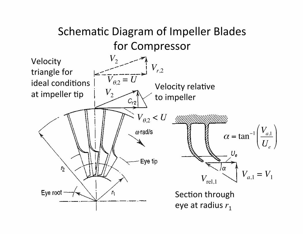
Schema0cDiagramofImpellerBladesforCompressor
WORK DONE AND PRESSURE RISE 129
In the first instance it will be assumed that the air enters the impeller eye in the axial direction, so that the initial angular momentum of the air is zero. The axial portion of the vanes must be curved so that the air can pass smoothly into the eye. The angle which the leading edge of a vane makes with the tangential direction ex will be given by the direction of the relative velocity of the air at inlet, Vi> as shown in Fig. 4.2.
If the air leaves the impeller tip with an absolute velocity Cz, it will have a tangential or whirl component Cw2, and a comparatively small radial component C,2. Under ideal conditions C2 would be such that the whirl component is equal to the impeller tip speed U, as shown by the velocity triangle at the top of Fig. 4.2. Due to its inertia, the air trapped between the impeller vanes is reluctant to move round with the impeller, and we have already noted that this results in a higher static pressure on the leading face of a vane than on the trailing face. It also prevents the air from acquiring a whirl velocity equal to the impeller speed. This effect is known as slip. How far the whirl velocity at the impeller tip falls short of the tip speed depends largely upon the number of vanes on the impeller. The greater the number of vanes, the smaller the slip, i.e. the more nearly Cw2 approaches U It is necessary in design to assume a value for the slip factor rJ, where rJ is defined as the ratio Cw21U Various approximate analyses of the flow in an impeller channel have led to formulae for rJ: the one appropriate to radial-vaned impellers which seems to agree best with experiment is that due to Stanitz, Ref. (4):
0·63n rJ=l---
n where n is the number of vanes.
Ideal conditions at impeller tip
FIG. 4.2 Nomenclature
/ Velocity relative to impeller
Section through eye at radius r1
Velocitytriangleforidealcondi0onsatimpeller0p
Velocityrela0vetoimpeller
Sec0onthrougheyeatradiusr1
Va,1 = V1
Vr,2
Vθ,2 < U
V2
V2
Vθ,2 = U
Vrel,1
α = tan−1 Va,1Ue
"
#$
%
&'

Euler’sTurbo-machineryEqua0onAngularmomentumequa0onforacontrolvolumeonimpeller:Assumingsteadyflow,negligibletorqueduetosurfaceforces(fric0on)withrespecttolargeshaFtorque,andmassisbalancedsotorquescancelout(likeatop):NOTE:TorqueappliedtoshaFequalschangeinangularmomentumofthefluid
!r ×!F∑ =
∂∂t
!r ×!V ρ dV
CV∫ +!r ×!V ρ!V ⋅ !n dA
CS∫
Tshaft = !m r2 Vθ 2 − r1 Vθ1( ) where !m = ρ!V ⋅ !n dA
CS∫

PowerDeliveredtoCompressorShaF
Sha;powerorrateofworkdoneontheshaFis:Foridealswirl-freeinletflow:Forbladevelocity,U = ω r2,andslipra$o,σ = Vθ2/U:Forpowerinputfactor,ψ≈1.035to1.04:
!Ws, ideal ="ω ⋅!Ts =ω r2 Vθ 2 − r1 Vθ1( ) !m
!Ws, ideal !m =σ U 2
!Ws, ideal !m =ω r2 Vθ 2
!Wc !m =ψ σ U 2 = cp T02 −T01( )
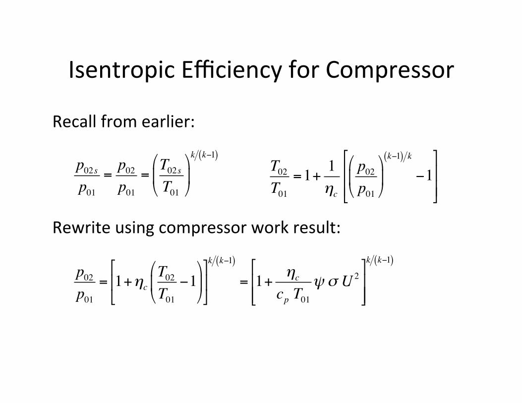
IsentropicEfficiencyforCompressor
Recallfromearlier:Rewriteusingcompressorworkresult:
p02sp01
=p02p01
=T02sT01
!
"#
$
%&
k k−1( )T02T01
=1+ 1ηc
p02p01
!
"#
$
%&
k−1( ) k
−1(
)
**
+
,
--
p02p01
= 1+ηcT02T01
−1"
#$
%
&'
(
)*
+
,-
k k−1( )
= 1+ ηc
cp T01ψ σ U 2
(
)**
+
,--
k k−1( )

NotesonPowerInputFactor,SlipFactor,andIsentropicEfficiency
• Allthreevariablesdependononeanother• ψrepresentsincreaseinworkinputduetofric0onintheimpellerbladewhichraisestheoutlettemperatureandtheturbineinlettemperature
• ηcalsoincludesfric0onallossesinthediffuser• σ(modeledasσ= 1 - 0.63 π/n for n vanes)limitsworkcapacityevenunderisentropiccondi0ons,thusmaximizebyaddingvanes,butthisaddsfric0on;typicallyuse19to21vanesforagoodtrade-off

NotesonPressureRa0o
• Increasingtheimpeller0pspeed,U,increasesthepressurera0oasexpected– Forsinglesidedimpellersoflightalloysthereisamaximumofabout460m/sduetolimita0onsoncentrifugalstresses;correspondstorpupto4
– Higherspeedsareobtainedwith0tanium,etc.;correspondstorpupto8
• Loweringtheinlettemperature,T01,alsoincreasesthepressurera0o,butthisisusuallynotpossible

Example#9Asingle-sidedcompressoristobedesignedbasedonthespecifica0onsinTable4.a. Determinethepressurera0oofthecompressorandpower
requiredtodriveitassumingthatthevelocityoftheairattheinletisswirlfree.
b. Calculatetheinletangleoftheimpellervanesattherootand0pradiioftheeyeassumingthattheaxialinletvelocityisuniformacrosstheeyeannulus.
c. Calculatethestagna0onpressureandtemperatureoftheairatexitoftheimpellerassumingtheradialvelocityoftheairattheexitisthesameastheaxialvelocityoftheairattheentranceoftheimpeller.

Table4.CompressorSpecifica<ons
Isentropiccompressorefficiency,ηc 0.78Powerinputfactor,ψ 1.04Slipfactor,σ 0.90Rota0onalspeed,N 290rev/sOveralldiameterofimpeller,D 0.50mEye0pdiameter,De,tip 0.30mEyerootdiameter, De,root 0.15mAirmassflowrate, 9kg/sInletstagna0ontemperature,T01 295KInletstagna0onpressure,p01 110kPaIsentropicefficiencyofimpeller,ηc,imp 0.89Heightofimpelleratexit,b2 1.76cm
!m

136
I I -----, ---
i FIG. 4.4 Impeller with backswept vanes
4.3 The diffuser
CENTRIFUGAL COMPRESSORS
Radial vanes (no slip)
In Chapter 6 it will be seen that the problem of designing an efficient combustion system is eased if the velocity of the air entering the combustion chamber is as low as possible. It is necessary, therefore, to design the diffuser so that only a small part of the stagnation temperature at the compressor outlet corresponds to kinetic energy. Usually the velocity of the air at the compressor outlet is in the region of 90 rnls.
As will be emphasized throughout this book, it is much more difficult to arrange for an efficient deceleration of flow than it is to obtain an efficient acceleration. There is a natural tendency in a diffusing process for the air to break away from the walls of the diverging passage, reverse its direction, and flow back in the direction of the pressure gradient-see Fig. 4.5(a). If the divergence is too rapid, this may result in the formation of eddies with consequent transfer of some kinetic energy into internal energy and a reduction in useful pressure rise. A small angle of divergence, however, implies a long diffuser and a high value of skin friction loss. Experiments have shown that the optimum included angle of divergence is about 7 degrees, although angles of up to twice this value can be used with diffusers of low length/width (or radius) ratio without incurring a serious increase in stagnation pressure loss. Empirical design curves for diffusers of both circular and rectangular cross-section can be found in Ref. (8). During acceleration in a converging passage, on the other hand, the gas naturally tends to fill the passage and follow the boundary walls closely, as in Fig. 4.5(b), however
Vθ,2 < U
• Forradialvanesbladeangleβ=0˚;forbacksweptvanes30˚<β<40˚
• Usedforhigh-performancecompressorsforhighefficiencyandwiderairflowrange
V2
Vrel,2
ImpellerwithBacksweptVanes
Radialvanesvelocitytriangle(fornoslip)shownbydoRedlines
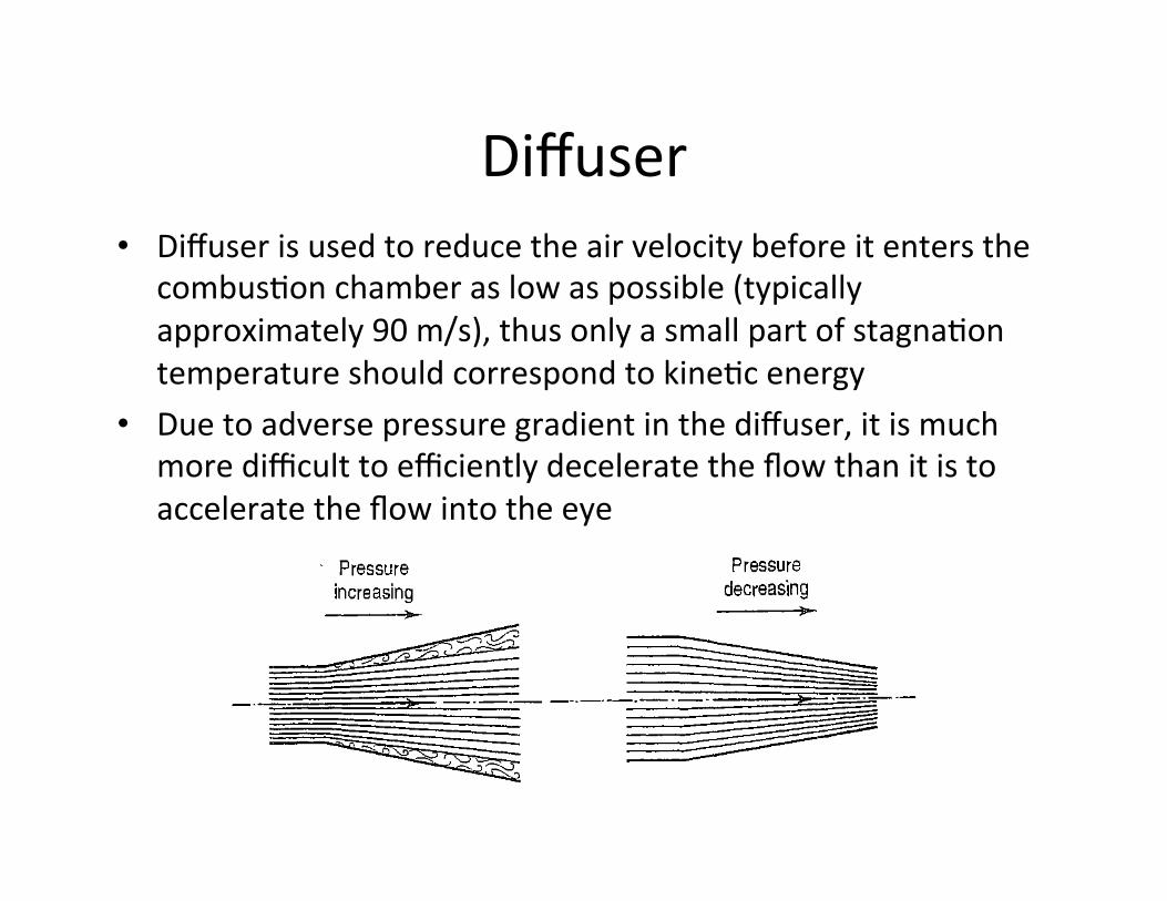
Diffuser• Diffuserisusedtoreducetheairvelocitybeforeitentersthe
combus0onchamberaslowaspossible(typicallyapproximately90m/s),thusonlyasmallpartofstagna0ontemperatureshouldcorrespondtokine0cenergy
• Duetoadversepressuregradientinthediffuser,itismuchmoredifficulttoefficientlydeceleratetheflowthanitistoacceleratetheflowintotheeyeTHE DIFFUSER
Pressure increasing
(a)
FIG. 4.5 Diffusing and accelerating liow
Pressure decreasing
137
rapid the rate of convergence. Only the normal frictional losses will be incurred in this case.
In order to control the flow of air effectively and carry out the diffusion process in as short a length as possible, the air leaving the impeller is divided into a number of separate streams by fixed diffuser vanes. Usually the passages formed by the vanes are of constant depth, the width diverging in accordance with the shape of the vanes, as shown in Fig. 4.1. The angle of the diffuser vanes at the leading edge must be designed to suit the direction of the absolute velocity of the air at the radius of the leading edges, so that the air will flow smoothly over the vanes. As there is always a radial gap between the impeller tip and the leading edges of the vanes, this direction will not be that with which the air leaves the impeller tip. The reason for the vaneless space after the impeller will be explained in section 4.4, when the effects of compressibility in this region are discussed.
To find the correct inlet angle for the diffuser vanes, the flow in the vaneless space must be considered. No further energy is supplied to the air after it leaves the impeller so that, neglecting the effect of friction, the angular momentum Cwr must be constant. Hence Cw decreases from impeller tip to diffuser vane ideally in inverse proportion to the radius. For a channel of constant depth, the area of flow in the radial direction is directly proportional to the radius. The radial velocity C,. will therefore also decrease from impeller tip to diffuser vane, in accordance with the equation of continuity. If both Cr and Cw decrease, then the resultant velocity C will decrease from the impeller tip, and some diffusion evidently takes place in the vaneless space. The consequent increase in density means that C,. will not decrease in inverse proportion to the radius as does Cw, and the way in which C,. varies must be found from the continuity equation. An example at the end of this section will show how this may be done. When C,. and Cw have been calculated at the radius of the leading edges of the diffuser vanes, then the direction of the resultant velocity can be found and hence the inlet angle of the vanes.
It will be apparent that the direction of the air flow in the vaneless space will vary with mass flow and pressure ratio, so that when the 1;ompressor is operating under conditions other than those of the design point the air may not flow smoothly into the diffuser passages in which event some loss of efficiency will result. In gas turbines where weight and complexity are not so important as high
DiffuserPerformance• Basedonexperimentalandnumericalfluidmechanics
studies,anop0mumincludedangleofdivergenceisapproximately7˚,althoughanglesupto14˚canbeusedforlowlengthtoradius(orwidth)withoutsignificantlosses
• Inaddi0on,airleavingtheimpellerisdividedintoseparatestreamsbyfixeddiffuservanesatanangledesignedtomatchtheairabsolutevelocitydirec0on
• Duetoaradialgapbetweentheimpellerbladeexitandthesta0onaryvanes(forcompressibilityissues)theairflowdirec0onwillchangeinthisregionwhichmustbeaccountedfortodeterminesta0onaryvaneangles
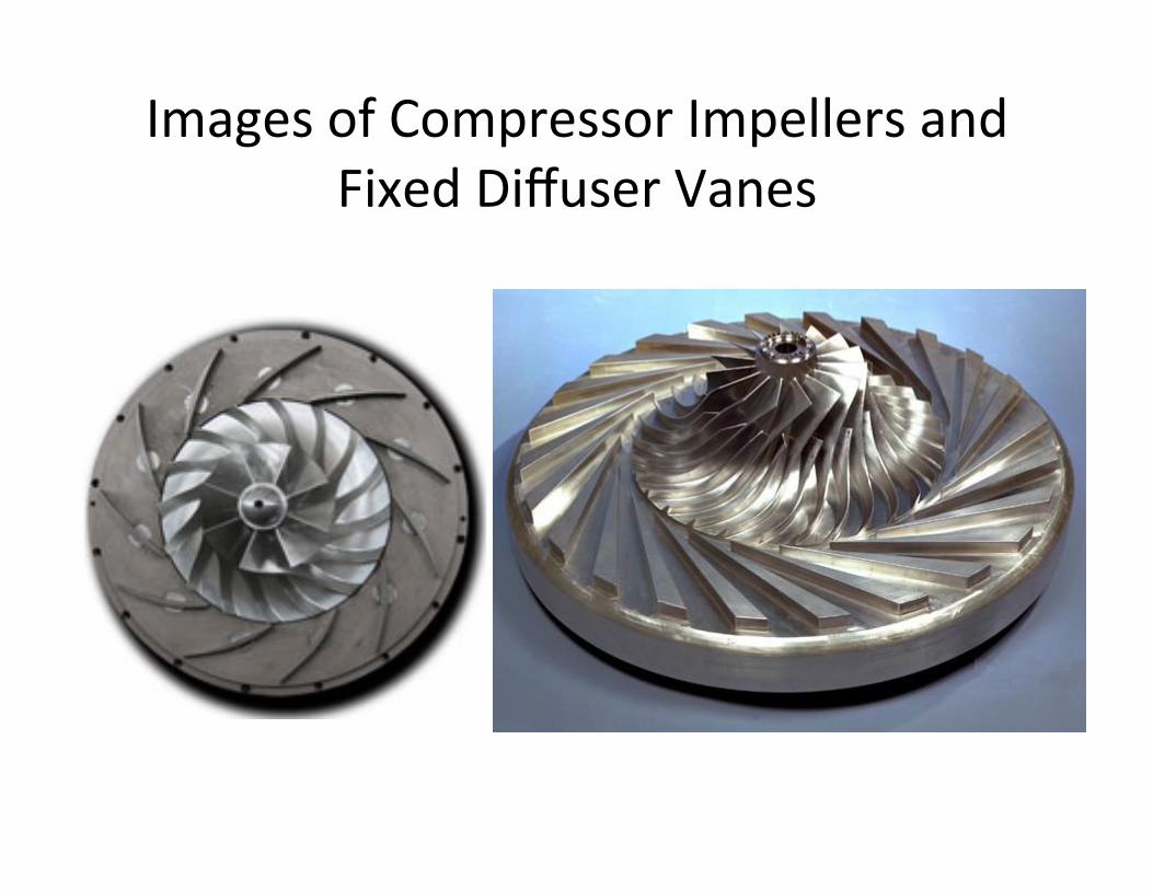
ImagesofCompressorImpellersandFixedDiffuserVanes

DiffuserVaneAngleCalcula0on• Forflowintheradialgapbetweenthebladeexitand
sta0onaryvanestheangularmomentum,Vθ rcanbeassumedconstant,thusVθmustdecrease(ideallypropor0onalto1/r)whilethepressureincreases
• Becausetheareanormaltoradialdirec0onalsoincreaseswithr,radialvelocity,Vr,willalsodecrease(propor0onalto1/r byconserva0onofmassforincompressible,butnotforthiscase)
• SincebothVθandVrdecrease,absolutefluidvelocitymagnitude,V,mustalsodecrease
• Calcula0onsofVθandVrareusedtofindthedirec0onoftheflowandtheangleforthesta0onaryvaneentrance

NotesonDiffuserVaneAngle
• Direc0onoffluidvelocitydependsonmassflowrateandpressurera0o,thusforopera0onawayfromthedesignpointmisalignmentbetweentheflowandvanesresultsinadecreaseinefficiency
• Forapplica0onswhereweightandcomplexityarenotasimportantaspar0al-loadefficiency,adjustablevanescanbeusedtochangetheangle

DiffuserGeometryCalcula0on
• ForgivenTandpatleadingedgeofdiffuservanes,massflowratecanbedeterminedforaspecifiedtotalthroatareaofthediffuserpassages
• Typicallythenumberofvanes(usuallymuchlessthanthenumberofimpellerbladeswhichwillbejus0fiedlater)andpassagedeptharealsospecified
• ThroatwidthisthencalculatedtoobtainthedesiredTandpalongthepassage
• Lengthofthediffuserpassageisdeterminedbytheacceptablemaximumdiffuserangle

DiffuserVanesandVolutes
• AFertheairexitsthediffuservanes,itmaypassintoavolute(orscroll)beforegoingtothecombus0onchamber(viaaheatexchangerifused)
• However,somesmallercompressorsuseonlydiffuservanesorjustavolute
• ForaircraF,individualstreamsmayberetainedwitheachindividualpassageconnectedtoeither:– separatecombus0onchambersor– fedintoanannularcombus0onchambersurroundingthecompressor/turbineshaF

Example#10AdiffuseristobedesignedforthecompressorinExample#9withthespecifica0onsgiveninTable5.Determinetheinletangleofthediffuservanes.
Radialwidthofvanelesszone,r3 – r2 5.0cmMeanradiusofdiffuserthroat,Rd,th 0.33mHeightofdiffuserpassages,bdiff 1.76cmNumberofdiffuservanes,Nv 12
Table5.DiffuserSpecifica<ons

CompressibilityEffects
• Ifthefluidvelocityrela0vetoitsboundingsurfacesnearsthespeedofsound(orgetsclosetoaMachnumberof1),excessivepressurelosseswilloccurduetosignificantboundarylayersepara0onandrecircula0on
• Inaddi0on,ifthesonicvelocityisexceededdestruc0veshockwavesmayform
• MorelikelytooccurinaircraFengineswheresmallcompressorsarerunatveryhighspeedsathighal0tudewherethespeedofsoundislower
• GooddesignslimittheMachnumbertobelow0.8

InletMachNumberforImpellerandDiffuser
• Attheintake,airisdeflectedthroughananglebeforepassingintoradialchannelsontheimpeller
• Thereisanaturaltendencyfortheairtobreakawayfromtheconvexfaceofthecurvedpartoftheimpellervane
• LocalMachnumberatthisloca0onisveryimportantbecauseashockwavemayoccur
• Rela0vevelocitycanbereducedbyintroducing“pre-whirl”attheintakeusingcurvedinletguidevanesaRachedtothecompressorcasing,butthisalsoreducesworkcapacitybecausewenolongerhave“swirl-free”entry

142 CENTRIFUGAL COMPRESSORS
certain points in the flow do not exceed the value beyond which the losses increase rapidly due to the formation of shock waves. The critical Mach number is usually less than unity when calculated on the basis of the mean velocity of the fluid relative to the boundary, because the actual relative velocity near the surface of a curved boundary may be in excess of the mean velocity. As a general rule, unless actual tests indicate otherwise, the Mach nmnbers are restricted to about 0·8.
Consider now the Mach numbers at vital points in the compressor, beginning with the intake.
Inlet Mach number for impeller and diffuser
At the intake, the air is deflected through a certain angle before it passes into the radial channels on the· impeller. There is always a tendency for the air to break away from the convex face of the curved part of the impeller vane. Here then is a point at which the Mach number will be extremely important; a shock wave might occur as shown in Fig. 4.7(a).
The inlet velocity triangle for the impeller eye is shown in Fig. 4.7(b). The full lines represent the case of axial inlet velocity which we have considered up to now. It has also been assumed that the axial velocity is uniform from the root to the tip of the eye. In dills case, the velocity of the air relative to the vane, will reach a maximum at the eye tip where the vane speed is greatest. The inlet Mach number will be given by
.j(yRT1)
where T1 is the static temperature at the inlet.
01: Breakaway commencing at rear ol shock wave
Cwl n (a)
FIG. 4.7 Effect of prewhirl
I I !7-,1 I I
I
Angle of '' prewhirl_,
Fixed inlet guide vane
t (b)

Non-DimensionalVariablesforPlosngCompressorCharacteris0cs
• Compressorperformancecanbespecifiedbycurvesofdeliverypressureandtemperatureversusmasflowrate,butthedependonothervariablessuchasentrypressureandtemperature,dimensions,andfluidproper0es
• Usingdimensionalquan00estorepresentperformancerequiresanexcessivenumberofexperimentsandplotsmakingaconcisepresenta0onimpossible
• Usingdimensionalanalysistocombinethevariablesintodimensionlessgroupsreducesthenumberofvariablesandallowsforfewerexperimentsandplotstobeusedtorepresentthesameinforma0on

NotesforCompressorVariables
• ItisconvenienttoconsiderRTasasinglevariablewithunitsof[L2T-2]
• Gasdensityisanimportantphysicalquan0tyforcompressors,butforRTandpalreadyincluded,becauseρ= p/RTisnotindependentitdoesnotneedtobeincluded
• Forthefullyturbulentflowsinacompressor,gasviscosity(whichwouldleadtotheinclusionoftheReynoldsnumberasoneofthedimensionlessgroups)doesnothaveasignificanteffectoverthenormalopera0ngrangeofacompressor

VariablesDimensionalAnalysis
Variablesthatsignificantlyeffectcompressorperformancefornormalopera0ngcondi0onsinclude:
D characteris0cdiameterN rota0onalspeedoftheimpeller massflowratethroughthecompressor
p01,p02 stagna0onpressuresattheinletandoutletT01,T02 stagna0ontemperateattheinletandoutlet
!m
DimensionlessGroups
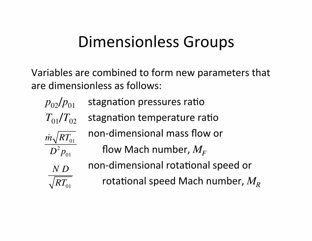
Variablesarecombinedtoformnewparametersthataredimensionlessasfollows:
p02/p01 stagna0onpressuresra0oT01/T02 stagna0ontemperaturera0o non-dimensionalmassflowor flowMachnumber,MF non-dimensionalrota0onalspeedor rota0onalspeedMachnumber,MR
!m RT01D2p01N DRT01

DimensionlessPlots
Onlynecessarytoplottwosetsofcurvestodescribetheperformanceofacompressorcompletely:1. Stagna0onpressureandtemperaturera0osversus
non-dimensionalmassflowforfixednon-dimensionalrota0onalspeeds
2. Isentropicefficiency(whichisalreadydimensionless)versusnon-dimensionalmassflowforfixednon-dimensionalrota0onalspeeds
TypicalCompressorPerformanceConsideracompressorrunningatconstantspeedwithavalveupstreamoftheinlet.• Whenthevalveisshutthemassflowiszeroandthe
pressurera0owillhavesomevalueAcorrespondingtothecentrifugalpressureheadproducedbytheac0onoftheimpellerontheairtrappedbetweenthevanes
• Asthevalveisopenedandflowcommences,thediffuserbeginstocontributetothepressureriseandthepressurera0oincreases
• AtsomepointB,theefficiencyreachesamaximumandthenstartstofallwithincreasingpressurera0oduetofric0onini0allyandthensepara0on/recircula0on

Theore0calEfficiencyCurve
COMPRESSOR CHARACTERISTICS 149
Before describing a typical set of characteristics, it will be as well to consider what might be expected to occur when a valve, placed in the delivery line of a compressor running at constant speed, is slowly opened. The variation in pressure ratio is shown in Fig. 4.8. When the valve is shut and the mass flow is zero, the pressure ratio will have some value A, corresponding to the centrifugal pressure head produced by the action of the impeller on the air trapped between the vanes. As the valve· is opened and flow commences, the diffuser begins to contribute its quota of pressure rise, and the pressure ratio increases. At some point B, where the efficiency approaches its maximum value, the pressure ratio will reach a maximum, and any further increase in mass flow will resuH in a fall of pressure ratio. For mass flows greatly in excess of that corresponding to the design mass flow, the air angles will be widely different from the vane angles, breakaway of the air will occur, and the efficiency will fall off rapidly. In this hypothetical case the pressure ratio drops to unity at C, when the valve is fully opened and all the power is absorbed in overcoming internal frictional resistance.
In actual practice, though poin1 A could be obtained if desired, most of the curve between A and B could not be obtained owing to the phenomenon of surging. Surging is associated with a sudden drop in delivery pressure, and with violent aerodynamic pulsation which is transmitted throughout the whole machine. It may be explained as follows. If we suppose that the compressor is operating at some point D on the part of the characteristic having positive slope, then a decrease in mass flow will be accompanied by a fall of delivery pressure. If the pressure of the air downstream of the compressor does not fall quicldy enough, the air will tend to reverse its direction and flow back in the direction of the resulting pressure gradient. When this occurs, the pressure ratio drops rapidly. Meanwhile, the pressure downstream of the compressor has fallen also, so that the compressor will now be able to pick up again to repeat the cycle of events which occurs at high frequency.
This surging of the air may not happen innnediately the operating point moves to the left of B in Fig. 4.8, because the pressure downstream of the compressor
o Constant
A "' "' 2! a..
o Mass flow
FIG. 4.8 Theoretical characteristic
• AtpointC,wherethepressurera0ois1,allthepowerinputisabsorbedinovercomingtheinternalresistance
• Inprac0ceopera0onbetweenpointsAandBcannotbereachedduetosurging
• Stableopera0oncanoccurfromBtoC

Surging
• Unstableopera0onwheretheflowoscillatesinbothdirec0onsandthepressurera0odropsrapidly
• Typicallystartstooccurindiffuserpassageswhereflowisretardedbyfric0onalforcesnearthevanes
• Tendencytosurgeincreaseswithnumberofvanesbecauseitisdifficulttosplittheflowofairsuchthatmassflowrateisthesameineachpassage
• Numberofdiffuservanesisusuallylessthannumberofimpellervanestoreducethelikelihoodofsurging

!50 CENTRIFUGAL COMPRESSORS
may first of all fall at a greater rate than the delivery pressure. Sooner or later, as the mass flow is reduced, the reverse will apply and the conditions are inherently unstable between A and B. As long as the operating point is on the part of the characteristic having a negative slope, however, decrease of mass flow is accompanied by a rise of delivery pressure and stability of operation is assured. In a gas turbine, the actual point at which surging occurs depends upon the swallowing capacity of the components downstream of the compressor, e.g. the turbine, and the way in which this swallowing capacity varies over the range of operating conditions.
Surging probably starts to occur in the diffuser passages, where the flow is retarded by frictional forces near the vanes: certainly the tendency to surge appears to increase with the number of diffuser vanes. This is due to the fact that it is very difficult to split the flow of air so that the mass flow is the same in each passage. When there are several diffuser channels to every impeller channel, and these deliver into a common outlet pipe, there is a tendency for the air to flow up one channel and down another when the conditions are conducive to surging. If this occurs in only one pair of channels the delivery pressure will fall, and thus increase the likelihood of surging. For this reason, the number of diffuser vanes is usually less than the number of impeller vanes. The conditions of flow are then approximately the same in each diffuser passage, because if each is supplied with air from several impeller channels the variations in pressure and velocity between the channels will be evened out by the time the air reaches the diffuser. Surging is therefore not likely to occur until the instability has reached a point at which reversal of flow will. occur in most of the diffuser passages simultaneously.
There is one other important cause of instability and poor performance, which may contribute to surge but can exist in the nominally stable operating range: this is the rotating stall. When there is any non-uniformity in the flow or geometry of the channels between vanes or blades, breakdown in the flow in one channel, say Bin Fig. 4.9, causes the air to be deflected in such a way that channel C receives fluid at a reduced angle of incidence and channel A at an increased incidence. Channel A then stalls, resulting in a reduction of incidence to channel B enabling the flow in that channel to recover. Thus the stall passes from channel to channel: at the impeller eye it would rotate in a direction opposite to the direction of
FIG. 4.9 Rotating stall
Rota0ngStall
• Occurswhentheeffec0veangleofaRackfortheflowoverthebladesbecomestoohigh(above15˚)resul0nginfullsepara0onattheleadingedgeofthebladeandalargeunstablerecircula0onzoneforms
• Anothercauseofinstabilityandpoorperformancethatcanalsocontributetosurge,butcanalsoexistinthenormallystableopera0ngrange
Choking
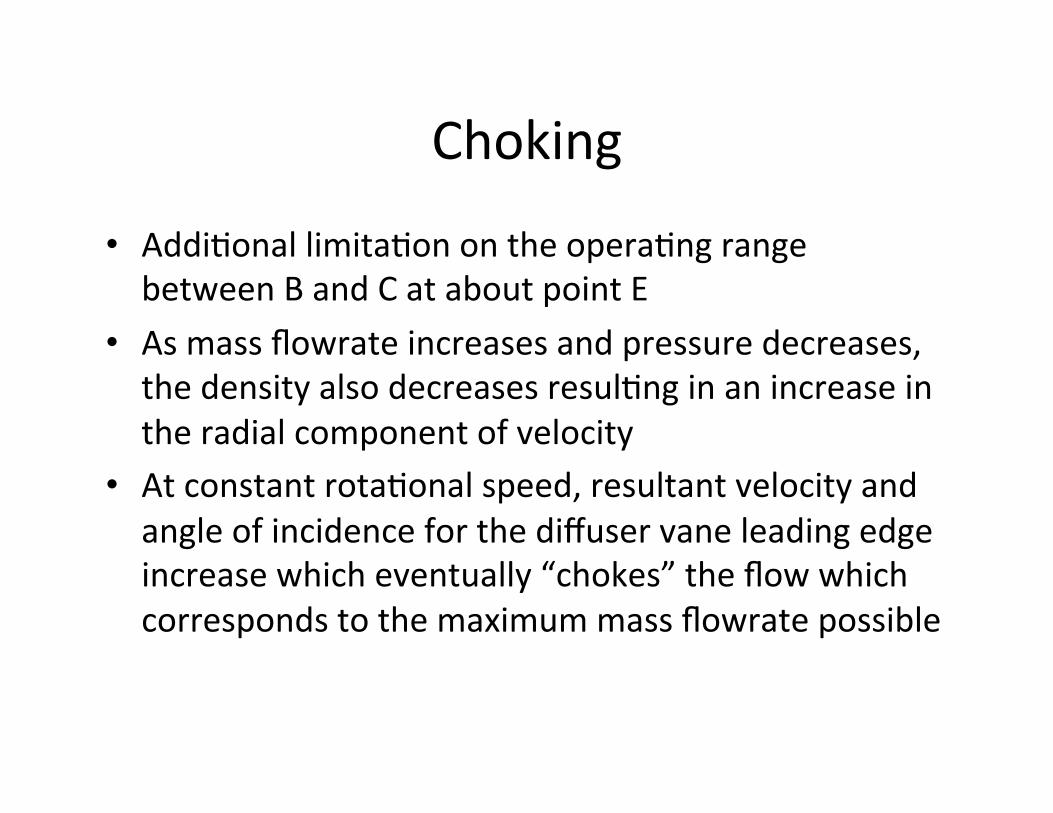
• Addi0onallimita0onontheopera0ngrangebetweenBandCataboutpointE
• Asmassflowrateincreasesandpressuredecreases,thedensityalsodecreasesresul0nginanincreaseintheradialcomponentofvelocity
• Atconstantrota0onalspeed,resultantvelocityandangleofincidenceforthediffuservaneleadingedgeincreasewhicheventually“chokes”theflowwhichcorrespondstothemaximummassflowratepossible

152 CENTRIFUGAL COMPRESSORS
PressureRa0oversusNon-DimensionalMassFlowandRota0onalSpeed
• T02/T01andp02/p01plotsareanalogous
• Flowischokedattherightside
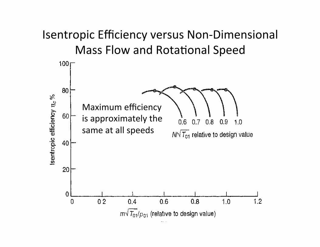
IsentropicEfficiencyversusNon-DimensionalMassFlowandRota0onalSpeed
152 CENTRIFUGAL COMPRESSORS
Maximumefficiencyisapproximatelythesameatallspeeds