Embed Size (px)
Citation preview

AIAA-2006-4778 42nd AIAA/ASME/SAE/ASEE Joint Propulsion Conference and Exhibit, Sacramento, California, July 9-12, 2006
American Institute of Aeronautics and Astronautics
1
Theoretical and Numerical Solutions of Linear and Nonlinear Elastic Waves in a Thin Rod
Minghao Cai,1 S.-T. John Yu,2 and Moujin Zhang3 The Ohio State University, Columbus, Ohio, 43202
In this paper, we report theoretical and numerical solutions of linear and nonlinear elastic waves in a thin rod. First, the classical solution of linear elastic wave in a thin rod is adapted such that it is ready to be compared with the numerical solution of a nonlinear formulation. Based on mass and momentum conservation, we then derive several forms of modeling equations for nonlinear elastic waves, including the contraction/expansion effect of the cross section of the thin rod. We then analyze the eigen-system of the nonlinear equations to show that the system is hyperbolic because the eigenvalues of the Jacobian matrices are real. Analytical forms of eigenvectors and Riemann invariants along characteristic lines are also derived. For numerical solutions, we identify a suitable conservative form, which is then solved by the space-time Conservation Element and Solution Element (CESE) method. Comparison between the numerical solution and the analytical solution is reported.
I. Introduction O model stress wave propagation in solids, standard text books 1-10 focus on linear elastic waves. The model equation is a second-order wave equation in terms of material displacement. For nonlinear stress waves, the
discussions have been focused nonlinear material response to elastic waves with emphasis on constructing complex constitutive relations.
The present paper focuses on a second category of the nonlinear waves, in which the material deformation is significant and the above approach of using a second-order wave equation is unsuitable. Instead, one has to solve the conservation laws, including conservation of mass, momentum, and even energy if severe impact is of concern. In particular, the nonlinear convective terms in the model equations must be included. The resultant modeling equations are a set of first-ordered, fully coupled, and nonlinear hyperbolic partial differential equations. The simplest first-ordered, hyperbolic equations for one-dimensional stress waves in a bulk material was presented by Bedford and Drumheller 3 and Drumheller 4. The equation set includes the mass and momentum conservation equations:
( )
0u
t xρρ ∂∂
+ =∂ ∂
(1)
( ) ( )
0u uu
t xρ ρ σ∂ ∂ −
+ =∂ ∂
(2)
where ρ is density, u is velocity, and ( )0 1Eσ ρ ρ= − is the Cauchy stress, expressed by a linear elastic relation with 0ρ as the initial density of the material. Alternatively, the hyperbolic equations for stress wave in solids could include the momentum conservation equation and a linear elastic constitutive equation 11-13:
1 0ut x
σρ
∂ ∂− =
∂ ∂ (3)
1 Ph.D. candidate, the Mechanical Engineering Department; Email: [email protected] 2 Associate Professor, the Mechanical Engineering Department; AIAA Member; Email: [email protected] 3 Research Associate, the Mechanical Engineering Department; AIAA Member.
T

AIAA-2006-4778 42nd AIAA/ASME/SAE/ASEE Joint Propulsion Conference and Exhibit, Sacramento, California, July 9-12, 2006
American Institute of Aeronautics and Astronautics
2
0uEt xσ∂ ∂− =
∂ ∂ (4)
Equation (3) is identical to Eq. (2) if ρ = constant. Equation (4) is obtained by first applying the time derivative to the constitutive equation Eσ ε= for a linear elastic material, and then letting t u xε∂ ∂ =∂ ∂ . Both forms of the equations could be recast into a vector form:
0t x
∂ ∂+ =
∂ ∂U UA . (5)
The unknown vector ( ), Tuρ ρ=U for Eqs. (1) and (2), and ( ), Tu σ=U for Eqs. (3) and (4). The eigenvalues of the Jacobian matrix A for Eqs. (1) and (2) are
1,2 2oE
uρ
λρ
= ± .
Both eigenvalues are real and the speed of sound of the solid is 2oEρ ρ . Thus, the equation set is hyperbolic in
time. Moreover, the equations are nonlinear because the eigenvalues are functions of the unknowns ρ and uρ . For Eqs. (3) and (4), the eigenvalues of matrix A are
1,2Euλρ
= ± .
Again, both eigenvalues are real and the speed of sound of the solid is E ρ . The eigenvalues here are identical to that of Eqs. (1) and (2) with ρ = constant. The above one-dimensional equations can be straightforwardly extended for problems in multiple spatial dimensions. The above simple constitutive equation for linear elastic mediums could also be extended for wave propagation in elastic-plastic materials. Moreover, one could also add the energy equation for impact problems at very high strain rate. Kulikovskii et al. 7 presented a nonlinear hyperbolic system for elastic-plastic problems, including mass, momentum, and energy conservation equations. In addition, a set of transport equations for deviatoric stress components were also included. These equations were obtained by applying the objective time derivative, D/Dt, to the elastic/plastic constitutive relation that embodies the material behavior. To close the model equations, an Equation of State (EOS) was included to relate temperature to pressure and density.
The first-order hyperbolic model equations are versatile and can be used to describe a wide range of waves in solids, including seismic waves in the earth and ultrasonic waves in biological tissues. Since the model equations directly include the nonlinear convective terms, one could also use these equations to model shock waves. In particular, the same set of the model equations could simultaneously describe nonlinear waves with large deformation and linear elastic waves, which tend to coexist with nonlinear deformations in solids.
The main challenge in employing the above hyperbolic equations is the development of viable numerical methods for time-accurate solutions. Conventional finite-volume method in conjunction with a Riemann solver has been used to solve this system of equations. When shock waves and contact discontinuity are of interest, a limiter functions is employed to treat the jump conditions. The original framework was developed by Godunov 14. Recent development of modern upwind schemes is an extension to the Godunov method in the following three aspects: (i) extension to second or higher order in both spatial and temporal resolution; (ii) development of more efficient approximate Riemann solvers; and (iii) development of sophisticated limiter functions for crisp resolution of jump conditions.
Colella 15 and Miller and Colella 16 presented an second-ordered Godunov method for direct calculations of waves in solids. Operator splitting was not applied in the two- and three-dimensional problems. The equations were written in non-conservative form, and deformation tensor was solved. Trangenstein 17, 18, and Trangenstein and Pember 19 developed a second-order extension of the Godunov method for impact problems involving multiple materials. Lin and Ballmann 13 used Zwas’ method 20 and reported numerical solutions of wave propagation around a crack. They combined the method of bi-characteristics and a finite-difference scheme for a second-order Godunov scheme 13. They validated their method by applying it to an anti-plane shear problem, a plane-strain problem 13, and an axisymmetric stress wave propagation 13. They also provided an extensive review of simulating stress waves in solids 13. LeVeque 21 used CLAWPACK and reported numerical solutions of multi-dimensional waves in solids. Udaykumar et al. 22 employed an ENO scheme and an interface tracking technique to calculate the problem of a

AIAA-2006-4778 42nd AIAA/ASME/SAE/ASEE Joint Propulsion Conference and Exhibit, Sacramento, California, July 9-12, 2006
American Institute of Aeronautics and Astronautics
3
tungsten rod impacting a steel plate. Fey 23, 24 proposed the method of transport, which does not rely on the use of a Riemann solver. The method was designed based on the concept of consistency of a set of wave vectors.
Owing to its simplicity and available analytical solution, one-dimensional elastic wave solutions often served as a reference to validate new numerical methods. In particular, when solving these one-dimensional nonlinear hyperbolic equations for linear elastic waves, the solutions must coincide with the classical solutions of the second-order wave equations. In the present paper, we plan to focus on the analytical and numerical solution of one-dimensional elastic wave in a thin rod. We remark that all existing one-dimensional, first-order hyperbolic model equations for elastic waves in solids describe longitudinal waves in bulk materials. For waves in a thin rod, although classical solutions based on solving the second-order wave equations have been ample, the solutions of the first-order model equations and analysis of the eigen-system have been scant. The present paper will present detailed derivation of the model equations, including the characteristic form, the non-conservative form, and the conservative form.
For numerical solutions, we will employ the space-time Conservation Element and Solution Element (CESE) method. Developed by Chang 25, the CESE method is a novel numerical framework for hyperbolic conservation laws. The tenet of the CESE method is a uniform treatment of space and time for flux conservation. Contrast to the modern upwind method, no Riemann solver or reconstruction step is used as a building block of the CESE method and the logic and operational count of the CESE method are simpler and more efficient. Based on the CESE method, a suite of computer one-, two-, and three-dimensional codes using structured and unstructured meshes have been developed. The two- and three-dimensional codes have been parallelized and can be used for large-scaled simulations. Previously, Yu and coworkers 25-34, have reported a wide range of highly accurate solutions of hyperbolic systems, including detonations, cavitations, complex shock waves, turbulent flows with embedded dense sprays, dam breaking flows, MHD flows, and aero acoustics. Detailed algebra of the method has been extensively illustrated in the cited references. For conciseness, only the basic ideas of the CESE method in one spatial domain will be illustrated in the present paper. The rest of this paper is organized in the following sections. Section 2 describes the problem of elastic wave propagating in a thin rod and presents the analytical solution based on solving the second-order wave equation. Section 3 illustrates the first-order model equations for nonlinear elastic waves in a thin rod. The eigen-system of the equation set is also derived. In Section 4, the CESE method for one-dimensional problems is illustrated. Section 5 provides results and discussions. We then provide the conclusion and the cited references.
II. Analytical Solution of Elastic Waves in a Thin Rod Analytical solutions for linear waves in solids have been ample, e.g., Graff 5, Kolsky 6 and Meirovitch 35. By using approximate Mindlin-Herrmann theory, Miklowitz 36 showed the analytical solution of elastic waves in a thin rod. He solved the problem of semi-infinite rod subject to a step pressure in the axial direction. He also solved waves in an infinite rod subject to an axial pressure load at the initial condition. In the present paper, Miklowitz’s solution is adapted. Instead of a step function, we will use a sinusoidal function as the imposed vibrations on one end of the thin rod.
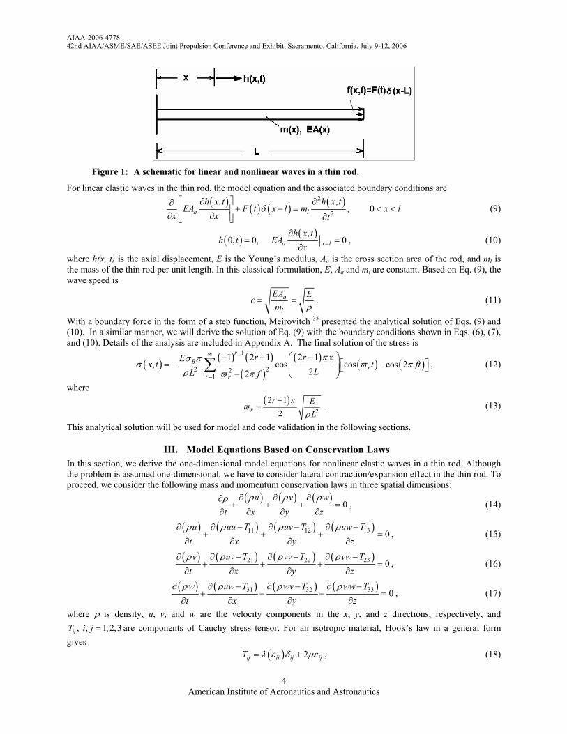
As shown in Figure 1, we consider a metal rod in a horizontal position. At x=0, the rod is fixed without motion. At x=l, an arbitrary force ( ),f x t is imposed in the following manner:
( ) ( ) ( ),f x t F t x lδ= − , (6)
where ( )F t assumes the form of
( )( ) cos 2B aF t A ftσ π= − , (7)
and ( )x lδ − is a Dirac delta function:
( ) ( )0
0 for and 1l
x l x l x l dxδ δ− = ≠ − =∫ . (8)
AIAA-2006-4778 42nd AIAA/ASME/SAE/ASEE Joint Propulsion Conference and Exhibit, Sacramento, California, July 9-12, 2006
American Institute of Aeronautics and Astronautics
4
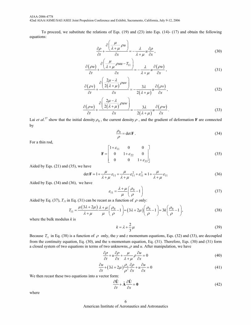
Figure 1: A schematic for linear and nonlinear waves in a thin rod.
For linear elastic waves in the thin rod, the model equation and the associated boundary conditions are
( ) ( ) ( ) ( )2
2
, ,, 0a l
h x t h x tEA F t x l m x l
x x tδ
∂ ∂∂+ − = < <
∂ ∂ ∂ (9)
( ) ( ),0, 0, 0a x l
h x th t EA
x =∂
= =∂
, (10)
where h(x, t) is the axial displacement, E is the Young’s modulus, Aa is the cross section area of the rod, and ml is the mass of the thin rod per unit length. In this classical formulation, E, Aa and ml are constant. Based on Eq. (9), the wave speed is
a
l
EA Ecm ρ
= = . (11)
With a boundary force in the form of a step function, Meirovitch 35 presented the analytical solution of Eqs. (9) and (10). In a similar manner, we will derive the solution of Eq. (9) with the boundary conditions shown in Eqs. (6), (7), and (10). Details of the analysis are included in Appendix A. The final solution of the stress is
( ) ( ) ( )( )
( ) ( ) ( )1
2 221
1 2 1 2 1, cos cos cos 2
22
rB
rr r
r r xEx t t ft
LL f
πσ πσ ϖ π
ρ ϖ π
−∞
=
− − − = − − −
∑ , (12)
where
( )2
2 12r
r EL
πϖ
ρ
−= . (13)
This analytical solution will be used for model and code validation in the following sections.
III. Model Equations Based on Conservation Laws In this section, we derive the one-dimensional model equations for nonlinear elastic waves in a thin rod. Although the problem is assumed one-dimensional, we have to consider lateral contraction/expansion effect in the thin rod. To proceed, we consider the following mass and momentum conservation laws in three spatial dimensions:
( ) ( ) ( )
0u v w
t x y zρ ρ ρρ ∂ ∂ ∂∂
+ + + =∂ ∂ ∂ ∂
, (14)
( ) ( ) ( ) ( )1311 12 0
uw Tu uu T uv Tt x y z
ρρ ρ ρ ∂ −∂ ∂ − ∂ −+ + + =
∂ ∂ ∂ ∂, (15)
( ) ( ) ( ) ( )2321 22 0
vw Tv uv T vv Tt x y z
ρρ ρ ρ ∂ −∂ ∂ − ∂ −+ + + =
∂ ∂ ∂ ∂, (16)
( ) ( ) ( ) ( )31 32 33 0
uw T wv T ww Twt x y z
ρ ρ ρρ ∂ − ∂ − ∂ −∂+ + + =
∂ ∂ ∂ ∂, (17)
where ρ is density, u, v, and w are the velocity components in the x, y, and z directions, respectively, and , , 1,2,3ijT i j = are components of Cauchy stress tensor. For an isotropic material, Hook’s law in a general form
gives ( ) 2ij ii ij ijT λ ε δ µε= + , (18)

AIAA-2006-4778 42nd AIAA/ASME/SAE/ASEE Joint Propulsion Conference and Exhibit, Sacramento, California, July 9-12, 2006
American Institute of Aeronautics and Astronautics
5
where ijε is the ( ),i j component of the strain tensor and added by summation convention ( ) 11 22 33iiε ε ε ε= + + , and λ and µ are Lame’s constants with µ as the shear modulus.
To proceed, consider one-dimensional longitudinal waves propagating in the thin rod, and the Cauchy stress T and the strain ε are
11 11 11
22 11
33 11
0 0 0 0 0 00 0 0 , and 0 0 0 00 0 0 0 0 0 0
Tv
v
ε εε ε
ε ε
= = = − −
T ε . (19)
where ν is the Poisson ratio:
( )2λνλ µ
=+
. (20)
Aided by Hook’s law, Eq. (18), and the strain tensor, Eq. (19), we have
( )( )( )
11 11 22 33 11
11 22 33 22
11 22 33 33
2
0 2
0 2
T λ ε ε ε µε
λ ε ε ε µε
λ ε ε ε µε
= + + +
= + + +
= + + +
The normal components of the strain tensor are not independent. They are constrained by
22 33 11λε ε ε
λ µ+ = −
+. (21)
Thus, 11T can be expressed as
( )
11 11 113 2
T Eµ λ µ
ε ελ µ
+= =
+
( )3 2where E
µ λ µλ µ
+=
+ (22)
Next, we consider the relation between velocity components. To be consistent with the strain shown in Eq. (19) with lateral contraction and expansion, the velocity components must satisfy the following relations:
, and .v u w uy x z x
ν ν∂ ∂ ∂ ∂= − = −
∂ ∂ ∂ ∂ (23)
Therefore, v and w are functions of y and z, respectively. To recap, for longitudinal wave in a thin rod, we could assume the following ( ), , ( , ), ( , , ), ( , , )x t u u x t v v x y t w w x z tρ ρ= = = = (24)
To further investigate the role of v and w in the model equations, we consider the strain tensor
1 , 1,2,32
jiij
j i
ddi j
x xε
∂∂= + = ∂ ∂
(25)
where id is a displacement component, and the components of symmetric part of gradient of velocity tensor D
1 , 1, 2,32
jiij
j i
vvD i j
x x
∂∂= + = ∂ ∂
(26)
Note that here 1 2 3 1 2 3, , , , ,v u v v v w x x x y x z= = = = = = . Obviously,
ijij
dD
dtε
= (27)
Equation (19) shows that 12 0ε = . Thus 12 0D = . Aided by u=u(x,t), i.e., Eq. (24), and following definition
1212
u vDy x
∂ ∂= + ∂ ∂
, (28)
we have 0v x∂ ∂ = , i.e. the velocity component v is not a function of x. Instead, ( , )v v y t= . Similarly, we have ( , )w w z t= . To recap, Eq. (24) can be updated as ( ), , ( , ), ( , ), ( , )x t u u x t v v y t w w z tρ ρ= = = = (29)
AIAA-2006-4778 42nd AIAA/ASME/SAE/ASEE Joint Propulsion Conference and Exhibit, Sacramento, California, July 9-12, 2006
American Institute of Aeronautics and Astronautics
6
To proceed, we substitute the relations of Eqs. (19) and (23) into Eqs. (14)- (17) and obtain the following equations:
u
ut x x
µ ρλ µρ λ ρ
λ µ
∂ +∂ ∂ + = −
∂ ∂ + ∂, (30)
( ) ( )11uu T
u uu
t x x
µ ρρ ρλ µ λ
λ µ
∂ − ∂ ∂+ + = −
∂ ∂ + ∂, (31)
( ) ( )
( )( )
22 3
2
uvv v
ut x x
µ λ ρλ µρ ρλ
λ µ
−∂ +∂ ∂ + = −
∂ ∂ + ∂, (32)
( ) ( )
( )( )
22 3
2
uww w
ut x x
µ λ ρλ µρ ρλ
λ µ
−∂ +∂ ∂ + = −
∂ ∂ + ∂. (33)
Lai et al.37 show that the initial density 0ρ , the current density ρ , and the gradient of deformation F are connected by
0 detρρ
= F . (34)
For a thin rod,
11
22
33
1 0 00 1 00 0 1
εε
ε
+ = + +
F (35)
Aided by Eqs. (21) and (35), we have
2 311 11 11 11det 1 1µ µ µε ε ε ε
λ µ λ µ λ µ= + + + ≈ +
+ + +F (36)
Aided by Eqs. (34) and (36), we have
011 1
ρλ µεµ ρ
+= −
(37)
Aided by Eq. (37), T11 in Eq. (31) can be recast as a function of ρ only:
( ) ( )0 0 0
113 2
1 3 2 1 3 1T kµ λ µ ρ ρ ρλ µ λ µ
λ µ µ ρ ρ ρ+ +
= − = + − = − + , (38)
where the bulk modulus k is
23
k λ µ= + (39)
Because 11T in Eq. (38) is a function of ρ only, the y and z momentum equations, Eqs. (32) and (33), are decoupled from the continuity equation, Eq. (30), and the x-momentum equation, Eq. (31). Therefore, Eqs. (30) and (31) form a closed system of two equations in terms of two unknowns, ρ and u. After manipulation, we have
0uut x xρ ρ µ ρ
λ µ∂ ∂ ∂
+ + =∂ ∂ + ∂
(40)
( ) 33 2 0ou uut x x
ρ ρλ µρ
∂ ∂ ∂+ + + =
∂ ∂ ∂ (41)
We then recast these two equations into a vector form:
t x
∂ ∂+ =
∂ ∂U UA 0 (42)
where

AIAA-2006-4778 42nd AIAA/ASME/SAE/ASEE Joint Propulsion Conference and Exhibit, Sacramento, California, July 9-12, 2006
American Institute of Aeronautics and Astronautics
7
uρ
=
U and ( ) 03
3 2
u
u
µ ρλ µ
λ µ ρ
ρ
+ = +
A . (43)
The eigenvalues of the coefficient matrix A is obtained by solving ( )det 0λ− =A I :
01,2 2
Eu u c
ρλ
ρ= ± = ± , and 0
2E
cρρ
= . (44)
where c is the speed of the sound. The eigenvalues are real and distinct and the system equations are hyperbolic. The eigenvalues are functions of the unknowns ρ and u. Thus, the equations are nonlinear. The associated eigenvectors could be obtained by solving the equation ( ) 1, 2i
i iλ− = =A I m 0 (45)
These two column eigenvectors are
( ) 01 1 11 2 2, 1,
TT E
m mρλ µ
µ ρ
+ = =
m
( ) 02 2 21 2 2, 1,
TT E
m mρλ µ
µ ρ
+ = = −
m
The right eigen-matrix M is composed of the two column vectors:
0 02 2
1 1
E Eρ ρλ µ λ µµ µρ ρ
= + + −
M (46)
Its inverse is denoted 1−M which can be readily found as
( )
( )
2
012
0
12 2
12 2
E
E
µ ρλ µ ρ
µ ρλ µ ρ
−
+ = − +
M (47)
To proceed, we derive the characteristic-form equations by pre-multiplying Eq. (42) by 1−M :
1 1 1
t x− − −∂ ∂
+ =∂ ∂U UM M AMM 0 . (48)
Note that we insert an identity matrix 1−=Ι MM in the convective term. Equation (48) can be expressed as
ˆ ˆ
t x∂ ∂
+ =∂ ∂U UΛ 0 , (49)
where the diagonal matrix Λ is
02
11
2 02
00
00
Eu
Eu
ρρλ
λ ρρ
−
+
= = =
−
Λ M AM . (50)
The characteristic variables are

AIAA-2006-4778 42nd AIAA/ASME/SAE/ASEE Joint Propulsion Conference and Exhibit, Sacramento, California, July 9-12, 2006
American Institute of Aeronautics and Astronautics
8
( )
( )
2
0112
2
0
12 2ˆˆ
ˆ 12 2
uEu
u uE
µ ρρλ µ ρ
µ ρρλ µ ρ
−
+
+ = = =
− +
U M U (51)
In the setting of the Method Of Characteristics (MOC), Eqs. (49)-(51) constitute the analytical solution of the nonlinear equations for elastic waves in a thin rod. In the x-t plane, along the characteristic lines 1,2dx dt λ= , the Riemann invariants 1,2u are constant:
ˆ
ˆ 0, 1, 2ii i
duu i
dt t xλ∂ ∂ = + = = ∂ ∂
(52)
Specifically, along the right running wave
02
Edx udt
ρρ
= +
we have
( )
2
0
12 2
uE
µ ρρλ µ ρ
++
= constant.
Similarly, along the left running wave
02
Edx udt
ρρ
= − ,
we have
( )
2
0
12 2
uE
µ ρρλ µ ρ
−+
= constant.
Direct integration along the right and left characteristic lines renders the complete analytical solution of nonlinear elastic waves in a thin rod. Moreover, since the analytical form of the MOC equations are derived, the boundary condition treatments at the two ends of the thin rod can also be readily obtained by following the characteristic waves in conjunction with the specified conditions in terms of ρ and u.
The above non-conservative form and characteristic equations, however, are insuitable for numerical solutions by using a finite-volume method. In order to perform space-time integration for flux conservation, we must transform the above equations into a conservative form:
t x
∂ ∂+ =
∂ ∂U F H (53)
where the conservative variables vector ( ), Tuρ ρ=U for mass and x-momentum conservation. The source term H on the right hand side of Eq. (53) is due to the contraction/expansion effect of the thin rod. By Gauss’ theorem, Eq. (53) can be recast into an integral form: ( ) where , , 1, 2T
i i i i id h d f u i∂Ω Ω
⋅ = Ω = =∫ ∫h s h (54)
where Ω is a space-time domain, ∂Ω is the surface of Ω , and if and iu are the ith component of F and U, respectively. Figure 2 shows a schematic of the space-time integration by Eq. (54).

AIAA-2006-4778 42nd AIAA/ASME/SAE/ASEE Joint Propulsion Conference and Exhibit, Sacramento, California, July 9-12, 2006
American Institute of Aeronautics and Astronautics
9
r+dr
r
dr
dsV
S(V)
t
x Figure 2: A schematic of space-time integral of the conservative-form equations.
This conservative-form equation is ready for numerical integration provided: (i) the eigenvalues of the the Jacobian matrix of the convection terms are real, i.e., the left hand side of (53) remains to be hyperbolic, and (ii) the source term can be straightforwardly integrated as a part of the overall space-time flux conservation. However, the conservative-form equations are not unique. In the present paper, we use the following formulation. To proceed, we substitute Eq. (22) into Eq. (31) and rewrite Eqs. (30) and (31) into the form of Eq. (53). The flux vector and source term vector are
1
2 03 1
uff
uu k
µ ρλ µ
ρµ ρλ µ ρ
+ = = − − +
F , and ( )
1
2
uxh
h uu
x
λ ρλ µ
ρλλ µ
∂ − + ∂ = = ∂ − + ∂
H .
The Jacobian matrix can be obtained by applying the chain rule to the convection term of Eq. (53):
t x t x t x
∂ ∂ ∂ ∂ ∂ ∂ ∂+ = + = + =
∂ ∂ ∂ ∂ ∂ ∂ ∂U F U F U U UA H
U (55)
2 0
2
0
32
ku u
µλ µ
ρµ µλ µ λ µρ
+∂ = = ∂ − + + +
FAU
(56)
The conservative form of this model is not unique. The one presented here is one of many options. By solving ( )det 0λ− =A I , we obtain the eigenvaluse of A as
( )
01,2 2
3ku
µρµλλ µ λ µ ρ
= ±+ +
(57)
Since these eigenvalues are real, this conservative form hyperbolic, and it could be solved by the CESE method or a suitable upwind method. These eigenvalues are artificial and they do not represent the true wave speeds of the hyperbolic system. Nevertheless, one has to use these artificial eigenvalues to determine a suitable time increment in time-marching calculation such that the CFL constraint is satisfied. The calculated wave speeds will be modulated by the source-term effect to render realistic wave speeds in the numerical solutions.
IV. The Space-Time CESE method To solve the above conservative-form equations, we employed the CESE method 25, which is a novel numerical framework for hyperbolic conservation law. In the CESE method, separated definitions of Solution Element (SE) and Conservation Element (CE) are introduced. In each SE, solutions of unknown variables are assumed continuous and a prescribed function is used to represent the profile. In the present calculation, a linear distribution is used. Over each CE, the space-time flux in the integral form, Eq.(54), is imposed.
Fig. 3 shows the space-time mesh and the associated SEs and CEs. Solutions of variables are stored at mesh nodes which are denoted by filled circular dots. A staggered mesh is used, and solution variables at neighboring SEs leapfrog each other in time-marching. The SE associate with each mesh node is denoted by a yellow rhombus. Inside the SE, the solution variables are assumed continuous. Across the interfaces of neighboring SEs, solution

AIAA-2006-4778 42nd AIAA/ASME/SAE/ASEE Joint Propulsion Conference and Exhibit, Sacramento, California, July 9-12, 2006
American Institute of Aeronautics and Astronautics
10
discontinuities are allowed. In this arrangement, solution information from on SE to another propagates through the oblique interface only in one direction, i.e., toward the future, as denoted by the red arrows. Through this space-time staggered mesh, the classical Riemann problem has been avoided. Fig. 3(b) illustrates a rectangular CE, over which the space-time flux conservation is imposed. This flux balance provides a relation between the solutions of three mesh nodes: ( ) ( ) ( ), , 1 2, 1 2 , and 1 2, 1 2j n j n j n− − + − . If the solutions at time step 1 2n − are known, the flux
conservation condition would determine the solution at ( ),j n .
(a) (b)
Fig. 3: Schematics of the CESE method in one spatial dimension: (a) zigzagging SEs; (b) integration over CE to solve ui and ( )x i
u at the new time level.
To proceed, we consider the one-dimensional equations with source terms:
m mm
u ft x
µ∂ ∂
+ =∂ ∂
, m = 1, 2. (58)
where the source term µm is the function of um. Let x1 = x, x2 = t and ( , )m m mf uh . By using Gauss’ theorem, we have
( )m m
S R Rd dRµ⋅ =∫ ∫h s (59)
For any (x, t) ∈ SE (j, n), um (x, t), fm (x, t) and hm (x, t), are approximated by *( , ; , )u x t j n , * ( , ; , )f x t j n , and *( , ; , )x t j nh , respectively. By assuming linear distribution in SEs, we have
( )* , ; , ( ) ( ) ( ) ( ) ( )n n n nm m j mx j j mt ju x t j n u u x x u t t= + − + − . (60)
Let ( )nm jf and ,( )n
m l jf denote the value of fm and ∂fm/∂ul, m, l = 1, 2, respectively, when um assumes the value of
( )nm ju . Let
2
,1
( ) ( ) ( )n n nmx j m l j lx j
l
f f u=∑ , (61)
and
2
,1
( ) ( ) ( )n n nmt j m l j lt j
l
f f u=∑ . (62)
Because
2
1
m m l
ll
f f ux u x=
∂ ∂ ∂=
∂ ∂ ∂∑ , and 2
1
m m l
ll
f f ut u t=
∂ ∂ ∂=
∂ ∂ ∂∑ , (63)

AIAA-2006-4778 42nd AIAA/ASME/SAE/ASEE Joint Propulsion Conference and Exhibit, Sacramento, California, July 9-12, 2006
American Institute of Aeronautics and Astronautics
11
( )nmx jf and ( )n
mt jf can be considered as the numerical analogues of the value of ∂fm/∂x and ∂fm/∂t at (xj, tn), respectively. As a result, we assume * ( , ; , ) ( ) ( ) ( ) ( ) ( )n n n n
m m j mx j j mt jf x t j n f f x x f t t= + − + − , (64) and * * *( , ; , ) ( ( , ; , ), ( , ; , ))m m mx t j n f x t j n u x t j n=h , (65)
Note that, by their definitions, for any m = 1, 2, ( )nm jf and ,( )n
m l jf are functions of ( )nm ju ; ( )n
mx jf are functions of
( )nm ju and ( )n
mx ju ; and ( )nmt jf are functions of ( )n
m ju and ( )nmt ju . Assume that, for any (x, t) ∈ SE (j, n), um =
* ( , ; , )mu x t j n and fm = * ( , ; , )mf x t j n satisfy Eq.(58), i.e.,
* *
*( , ; , ) ( , ; , )( , ; , )m m
mu x t j n f x t j n
x t j nt x
µ∂ ∂
+ =∂ ∂
(66)
According to Eqs. (60) and (64), and further assume that *mµ is constant within SE(j, n), i.e., * ( , ; , )m x t j nµ = ( )n
m jµ , the above equation is equivalent to ( ) ( ) ( )n n n
mt j mx j m ju f µ= − + . (67)
Since ( )nmx jf are functions of ( )n
m ju and ( )nmx ju ; and ( )n
m jµ are also functions of ( )nm ju , Eq. (67) implies that
( )nmt ju are also functions of ( )n
m ju and ( )nmx ju . Thus, the only independent discrete variables needed to be solved
are ( )nm ju and ( )n
mx ju . To proceed, we employ local space-time flux balance over CE(j, n) to solve the unknowns. Refer to Fig. 3(b).
Assume that *mu and *
mxu at mesh points ( )1 2, 1 2j n− − and ( )1 2, 1 2j n+ − are known and used to calculate
( )nm ju and ( )n
mx ju at the new time level n. By enforcing the flux balance over CE(j, n), i.e.,
* *
( ( , )) ( , )m m
S CE j n CE j nd dVµ⋅ =∫ ∫h s , (68)
one obtains
( ) ( )4
n nm j m j
tu µ∆− =
1/ 2 1/ 2 1/ 2 1/ 2 1/ 2 1/ 21/ 2 1/ 2 1/ 2 1/ 2 1/ 2 1/ 2
1 ( ) ( ) ( ) ( ) ( ) ( )2 4 4
n n n n n nm j m j m j m j m j m j
t tu u s sµ µ− − − − − −− + − + − +
∆ ∆ + + + + − , (69)
where 2( ) ( / 4)( ) ( / )( ) ( / 4 )( )n n n n
m j mx j m j mt js x u t x f t x f= ∆ + ∆ ∆ + ∆ ∆ . (70)
Given the values of the marching variables at mesh points ( )1 2, 1 2j n− − and ( )1 2, 1 2j n+ − , the RHS
of Eq. (69) can be readily calculated. Since ( )nm jµ on the LHS of Eq. (69) is a function of ( )n
m ju , we use Newton’s
method to solve for ( )nm ju .
To solve (umx)jn at point (j, n), central differencing is performed:
( ) [( ) ( ) ] / 2n n nx j x j x ju u u+ −= + , (71)
where 1/ 2( ) ( ) /( / 2)n n n
x j j ju u u x±±= ± − ∆ , (72)
1/ 2 1/ 21/ 2 1/ 2 1/ 2( / 2)( )n n n
j j t ju u t u− −± ± ±= + ∆ . (73)
For flows with discontinuities, Eq. (71) is replaced by a re-weighting procedure to add artificial damping: ( ) ( ( ) , ( ) , )n n n
x j x j x ju W u u α− += , (74) where the function W is defined as

AIAA-2006-4778 42nd AIAA/ASME/SAE/ASEE Joint Propulsion Conference and Exhibit, Sacramento, California, July 9-12, 2006
American Institute of Aeronautics and Astronautics
12
( , , )x x x x
W x xx x
α α
α αα + − − +− +
+ −
+=
+, (75)
and α is an adjustable constant. Usually α = 1 or 2. The above method with CE and SE defined as in Fig. 3 is useful for treating the conservation laws with non-stiff source terms.
To proceed, we consider the condition when the source term in Eq. (58) is stiff. We first normalize the source term and let *1m mµ κ µ= ⋅ , where the order of the magnitude of *
mµ is comparable with that of mu t∂ ∂ and mf x∂ ∂ . Aided by this normalized source term, Eq. (58) becomes
*1m mm
u ft x
µκ
∂ ∂+ =
∂ ∂, for m = 1, 2.
The source terms is stiff if 1κ . In other words, the time scale of the source term is much smaller than that of the convection term.
In numerical calculations, the magnitude of the source term would directly impact the calculation of ( )nmt ju ,
Eq.(67), and hence the calculation of ( )nmt jf , Eq. (62). Essentially, small difference between the value of 1/ 2
1/ 2( )nm ju −
−
and 1/ 21/ 2( )n
m ju −+ which will be amplified by the stiffness factor 1 κ , leading to amplified differences
between 1/ 21/ 2( )n
m jµ −− and 1/ 2
1/ 2( )nm jµ −
+ . This difference in turn would lead to the amplified differences between 1/ 21/ 2( )n
mt ju −− and 1/ 2
1/ 2( )nmt ju −
+ , and between 1/ 21/ 2( )n
mt jf −− and 1/ 2
1/ 2( )nmt jf −
+ . As a result, Newton’s method would fail to converge when solving this stiff relaxation system.
Due to the above difficulty, a modification to the original method has been developed to avoid the amplification effects. The new treatment was based on redistributing the space-time regions such that the source term effect is hinged on the mesh point at the new time level. Fig. 4 shows the new layout of CEs and SEs associated with mesh nodes. Shown in Fig. 4(b), the new SE is constituted by the rectangle ABB'A', the line segments QQ″, and the immediate neighborhood of QQ″. The CE is rectangle ABB'A'. Note that Q, Q' and Q″ share the same spatial projection, so do A and A', and B and B'. The superscript prime and quotation mark denote the time level n-1/2 and n+1/2, respectively. Besides the SE(j, n), two more neighboring SEs are also shown to illustrate the belonging (to SEs) of the three parts of CE(j, n).
With this new construction of SEs, we proceed to perform integration as in the original CESE method, and have Eqs. (60), (64), and (65). However, the evaluation of 1/ 2
1/ 2( )nmt ju −
− and 1/ 21/ 2( )n
mt ju −+ differs from the original
method by simply using 1/ 2 1/ 2
1/ 2 1/ 2( ) ( )n nmt j mx ju f− −
± ±= − , (76) and no source term effect is included. Note that these temporal derivatives are used only along the line segment protruding from the top of AA’B’B. The area of the line segment is zero due to the geometry of new SEs. This layout excludes the influence of the stiff source term from mesh nodes at time level 1 2n − in the overall space-time flux conservation.
(a) (b)
Fig. 4: Schematics of the modified CESE method in one spatial dimension: (a) the staggered space-time mesh; (b) SE (j, n), shown as the yellow part, and CE (j, n).

AIAA-2006-4778 42nd AIAA/ASME/SAE/ASEE Joint Propulsion Conference and Exhibit, Sacramento, California, July 9-12, 2006
American Institute of Aeronautics and Astronautics
13
Therefore, in the calculation of the overall flux balance over CE(j, n), i.e., Eq.(68), the integration of the source term is based on the flow properties at the mesh point (j, n), and one obtains
1/ 2 1/ 2 1/ 2 1/ 21/ 2 1/ 2 1/ 2 1/ 2
1( ) ( ) ( ) ( ) ( ) ( )2 2
n n n n n nm j m j m j m j m j m j
tu u u s sµ − − − −− + − +
∆ − = + + − , (77)
where 2( ) ( / 4)( ) ( / )( ) ( / 4 )( )n n n n
m j mx j m j mt js x u t x f t x f= ∆ + ∆ ∆ + ∆ ∆ . (78)
Similar to that in the original method, for any m = 1, 2, ( )nm jf and ( )n
m jµ are functions of ( )nm ju ; ( )n
mt jf is a
function of ( )nm jµ and ( )n
mx ju . Thus, given the values of the marching variables at t = tn-1/2, Eq. (77) is a nonlinear
equation of ( )nm jµ . Again, Newton’s iteration method is used. The algorithm for solving ( )n
mx ju in the modified method remains unchanged, i.e., by Eqs. (71)-(74).
Based on the above treatment, we avoid the amplification effect of the stiff source term in numerical calculations and thus stabilize the iterative procedure of Newton’s method. Essentially, the effect of the source-term calculation on the flow properties from the time level n − 1/2 was not involved. The layout of the modified SEs helps to eliminate the stiffness problem. Nevertheless, the union of all the CEs still covers the whole space-time domain without overlapping and the source-term effect would satisfy the local and global space-time flux balance in an integral sense.
V. Results and Discussions In the present paper, we consider elastic longitudinal wave propagating in an aluminum rod. For aluminum, 3
0 2700 /kg mρ = , 60.5GPaλ = , 26GPaµ = , 70E GPa= , and 77k GPa= . The length of the rod 1.0L m= . To be consistent with the forced boundary condition on the right end of the rod, Eq. (7), we assume that
the displacement applied at the right end of rod is a cosine function of time: ( )cos 2Ad C ftπ= − ⋅ (79) where d is the displacement, AC is the amplitude of the imposed vibrations, and f is the frequency of the imposed vibrations. In the present calculations, 50AC mµ= and 20f kHz= . Corresponding to the above vibrations, the velocity at right boundary is ( )2 sin 2B Au f C ftπ π= ⋅ ⋅ (80) We note that the amplitude of stress at boundary Bσ in stress boundary Eq. (7) must be provided to obtain the analytical solution of the second order wave equation, Eq. (12). To this end, we first use the CESE method to solve the conservative-form first-order equations, i.e., Eq. (55) to obtain Bσ , which is then used to obtain the analytical solution, Eq.(12), of the second-order linear wave equation.
(a) (b)
Fig. 5: (a) The stress variation at the vibrating end of the rod and (b) the speed of sound profile at t=0.312 ms calculated by the CESE method.

AIAA-2006-4778 42nd AIAA/ASME/SAE/ASEE Joint Propulsion Conference and Exhibit, Sacramento, California, July 9-12, 2006
American Institute of Aeronautics and Astronautics
14
By solving the nonlinear equations, Eq. (55), by the CESE method, we obtained the dynamics stress boundary condition and speed of sound. (a) (b)
Fig. 5(a) shows the time history of Bσ . About 6 cycles of vibrations were calculated. The solution shown in (a) (b)
Fig. 5(a) reveals that at a high frequency, imposed vibrations even with a small amplitude could generate higher stresses, which then propagate in the specimen at the speed of sound. (a) (b)
Fig. 5(b) shows a snapshot of the speed of sound profile at t = 0.312 ms. At this time, the wave initiated from the right end of the rod has reached and rebounded from the left end of the rod. Due to wave reflection, the wave amplitude increases. Since we solve the first order nonlinear equations, the speed of sound, which is a part of the eigenvalues, depends on the instantaneous solution of the primary unknowns ( ), Tuρ ρ=U . The initial speed of sound at 5092 m/s is denoted by a blue line. Because the density is not a constant in this process, the speed of sound shown in (a) (b)
Fig. 5(b) presents the fluctuation around the initial value at 5092m/s.
(a) (b)
Fig. 6: The snapshot (t=0.312ms) of stress wave propagation generated by (a) numerical solution of nonlinear wave model Eq. (55) and (b) theoretic solution of linear wave Eq. (12).
Fig. 6 shows the side-by-side comparison of the normal stress between (a) the CESE solution of Eq. (55), and (b) the analytical solution of Eq. (12). Fig. 6 demonstrate that for linear elastic wave problem, the nonlinear wave model, Eq.(55), solved by the CESE method can faithfully catch the linear elastic waves. These figures also show that the magnitude of the stress wave doubles after wave reflection from the left end of the rod. Fig. 7 shows the snapshot of density profile of the thin rod at the same time. Because of the nonlinear wave model, Eq.(55), density is not a constant. As wave propagates, density at a spatial location would fluctuate accordingly.

AIAA-2006-4778 42nd AIAA/ASME/SAE/ASEE Joint Propulsion Conference and Exhibit, Sacramento, California, July 9-12, 2006
American Institute of Aeronautics and Astronautics
15
Fig. 7: A snapshot (t=0.312ms) of density profile predicted by two-equations model, Eq. (55).
The capability of the CESE method in capturing stress waves could be assessed by the number of grid points
needed for resolving the propagating waves. Fig. 8 shows snapshots of profiles of normal stress at t = 0.312 ms. Three sets of solutions using 301, 151, and 75 grid points. When 75 mesh nodes are used, dissipation effect can be observed as compared to the solutions by using 151 and 301 mesh nodes. Although not shown, further mesh refinement does change the solution. In all three cases, no obvious dispersive effect can be discerned. Approximately, the one meter aluminum rod contents 3 cycles of wave. Therefore, we need at least about 25 nodes per wave length to resolve the stress wave.
Fig. 8: Snapshots of the normal stress profiles at t = 0.312 ms by using 301, 151, and 75 grid points.
VI. Conclusions The present paper reported detailed analyses of the first-order model equations and its eigen-system for nonlinear elastic stress waves in a thin rod. Based on the conservation laws of mass and momentum, model equations in non-conservative form, characteristic form, and conservative form were derived. Analytical solutions of the eigenvalues, eigenvector matrices, and the Riemann invariants along characteristic lines were provided. Due to the contraction/expansion effect of the cross section area of the thin rod, the derived model equations were quite complex. In particular, when put into a conservative form, a stiff source term appeared on the right hand side of the first-order hyperbolic equations. A suitable conservative form for numerical solutions was then solved by the space-time CESE method. The treatment for stiff source term was designed by re-distributing the space-time areas of SE

AIAA-2006-4778 42nd AIAA/ASME/SAE/ASEE Joint Propulsion Conference and Exhibit, Sacramento, California, July 9-12, 2006
American Institute of Aeronautics and Astronautics
16
such that the amplification effect by the stiff source term was avoided and the numerical integration was stabilized. For linear waves, favorable comparison between the numerical results and the classical solutions of the second-order wave equation was found. The result here is a steppingstone for the further development of the model equations and the CESE method for stress waves of large material deformation.
Appendix This appendix provides the derivation of the analytical solution of the second order linear wave equation for linear elastic wave in a thin rod. The process here is adapted from that of Miklowitz.36 To solve Eqs. (9) and (10), we first solve the eigenvalue problem defined by the following differential equation
( ) ( )2 , 0a l
dH xd EA m H x x Ldx dx
ϖ
− = < <
(A.1)
With the boundary conditions
( ) ( )0 0, 0a x L
dH xH EA
dx == = (A.2)
The solution consist of the eigenvalues 2rϖ (r = 1,2,…) and the eigen-functions ( )rH x , which are mutually
orthogonal and normalized. Thus, the eigen-functions satisfy the following ortho-normal condition:
( ) ( )0
, , 1, 2,...L
l r s rsm H x H x dx r sδ= =∫ (A.3)
and
( ) ( ) 2
0, , 1,2,...
L rs a r rs
dH xdH x EA dx r sdx dx
ϖ δ
− = =
∫ (A.4)
The solution is assumed in the form as
( ) ( ) ( )1
, , 1,2,...r rr
h x t H x t rη∞
=
= =∑ (A.5)
Substituting Eq. (A.5) in to Eq. (9), multiplying by ( )sH x , integrating over the length of the rod, and considering the ortho-normal condition, i.e., (A.3) and (A.4), we have the modal equations ( ) ( ) ( )2 , 1, 2,...r r r rt t N t rη ϖ η+ = = (A.6) where
( ) ( ) ( ) ( ) ( ) ( )0
, 1, 2,...L
r r rN t H x F t x L dx H L F t rδ= − = =∫ (A.7)
are the modal forces. The solution of the modal equations can be written in the form of the convolution integrals
( ) ( ) ( ) ( ) ( ) ( )0 0
1 sin sin , 1, 2,...t tr
r r r rr r
H Lt N t d F t d rη τ ϖ τ τ τ ϖ τ τ
ϖ ϖ= − = − =∫ ∫ (A.8)
The displacement response of the rod to the boundary force is described by the Eqs. (A.5) and (A.7). For the uniform rod shown in Figure 1, the eigenvalue problem is governed by the following differential equation:
( ) ( )
2 22 2
2 0, 0 , l
a
d H x mH x x L
EAdxϖ
β β+ = < < = (A.9)
with the boundary conditions
( ) ( )0 0, 0x L
dH xH
dx == = (A.10)
The ortho-normal modes in the solution of this eigenvalue problem are
( ) ( )2 12 sin , 1,2,...2r
l
r xH x r
m L Lπ −
= =
(A.11)
The natural frequencies are

AIAA-2006-4778 42nd AIAA/ASME/SAE/ASEE Joint Propulsion Conference and Exhibit, Sacramento, California, July 9-12, 2006
American Institute of Aeronautics and Astronautics
17
( )
2
2 1, 1, 2,...
2a
rl
r EAr
m L
πϖ
−= = (A.12)
When we apply a specific force boundary condition as Eq.(A.7), we could calculate the response of the rod by following steps. Aided by Eqs. (A.8), (A.11) and (A.12), we have
( ) ( ) ( ) ( )
( )( )
( ) ( )
0
22
cos 2 sin
2 12 sin cos cos 2 , 1, 2,...2 2
trr a B r
r
a Br
a r
H Lt A f t d
r At ft r
m L f
η σ π τ ϖ τ τϖ
π σϖ π
ϖ π
= − −
− = − − = −
∫ (A.13)
Substituting Eqs.(A.11) and (A.13) into Eq.(A.5), we have the displacement response of the rod to the applied force by Eq. (A.7). We then use the known displacement response to calculate the stress:
( ) ( )
( )( )
( ) ( ) ( ) ( )
( ) ( )( )
( ) ( ) ( )
2 221
1
2 221
,,
2 1 2 1 2 1 sin cos cos cos 2
2 22
1 2 1 2 1 cos cos cos 2
22
Br
r rr
Br
r r
h x tx t E
xr r r xE
t ftLL f
r r xEt ft
LL f
σ
π πσ πϖ π
ρ ϖ π
πσ πϖ π
ρ ϖ π
∞
=
−∞
=
∂=
∂ − − −
= − − −
− − − = − − −
∑
∑
(A.14)
where
( )2
2 12r
r EL
πϖ
ρ
−= . (A.15)
In this derivation, we use
l
a
mA
ρ = (A.16)
References 1Achenbach, J. D., Wave Propagation in Elastic Solids, North-Holland, Amsterdam, 1973 2Antman, S. S., Nonlinear Problems of Elasticity, Springer-Verlag, New York, 1995 3Bedford, A., and Drumheller, D. S., Introduction to Elastic Wave Propagation, John Wiley & Sons, Inc., New York, 1993 4Drumheller, D. S., Introduction to Wave Propagation in Nonlinear Fluids and Solids, Cambridge University Press, New
York, 1998 5Graff, K. F., Wave Motion in Elastic Solids, Dover Publications, INC., New York, 1991 6Kolsky, H., "An Investigation of the Mechanical Properties of Materials at Very High Rates of Strain," Proceedings of the
Royal Society of London, Vol. B62, 1949, pp. 676-700 7Kulikovskii, A. G., Pogorelov, N. V., and Semenov, A. Y., Mathematical Aspects of Numerical Solution of Hyperbolic
Systems, Chapman & Hall/CRC, Boca Raton, Florida, 2001 8Landau, L. D., and Lifshitz, E. M., Theory of Elasticity, Pergamon Press, 1975 9Sokolnikoff, I. S., Mathematical Theory of Elasticity, McGraw-Hill, New York, 1956 10Veubeke, B. M. F. d., A Course in Elasticity, Springer, New York, 1979 11LeVeque, R. J., Finite Volume Methods for Hyperbolic Problems, Cambridge University Press, New York, 2002 12Giese, G., and Fey, M., "A Genuinely Multidimensional High-Resolution Scheme for the Elastic–Plastic Wave Equation,"
Journal of Computational Physics, Vol. 181, 2002, pp. 338-353 13Bechtel, S. E., Lin, K. J., and Forest, M. G., "Effective Stress Rates of Viscoelastic Free Jets," Journal of Non-Newtonian
Fluid Mechanics, Vol. 26, 1987, pp. 1-41 14Godunow, S. K., "Die Differenzenmethode Zur Numerischen Berechnung Von Unstetigkeitslosungen Hydrodynamischer
Gleichungen," Mat. Sb., Vol. 47, 1959, pp. 15Collela, P., "Multidimensional Upwind Methods for Hyperbolic Conservation Laws," Journal of Computational Physics,
Vol. 87, 1990, pp. 171-200 16Miller, G. H., and Colella, P., "A High-Order Eulerian Godunov Method for Elastic–Plastic Flow in Solids," Journal of
Computational Physics, Vol. 167, 2001, pp. 131-176 17Trangenstein, J. A., "A Second-Order Algorithm for the Dynamic Response of Soils," IMPACT of Computing in Science
and Engineering, Vol. 2, 1990, pp. 1-39

AIAA-2006-4778 42nd AIAA/ASME/SAE/ASEE Joint Propulsion Conference and Exhibit, Sacramento, California, July 9-12, 2006
American Institute of Aeronautics and Astronautics
18
18Trangenstein, J. A., "Adaptive Mesh Refinement for Wave Propagation in Nonlinear Solids," SIAM: SIAM Journal on Scientific Computing, Vol. 16, 1995, pp. 819-939
19Trangenstein, J. A., and Pember, R. B., "The Riemann Problem for Longitudinal Motion in an Elastic-Plastic Bar," SIAM Journal on Scientific and Statistical Computing, Vol. 12, 1991, pp. 180-207
20Eilon, B., Gottlieb, D., and Zwas, G., "Numerical Stablizers and Computing Time for Second-Order Accurate Schemes," Journal of Computational Physics, Vol. 9, 1972, pp. 3887-3397
21LeVeque, R. J., "Wave Propagation Algorithms for Multidimensional Hyperbolic Systems," Journal of Computational Physics, Vol. 131, 1997, pp. 327 - 353
22Tran, L. B., and Udaykumar, H. S., "A Particle-Level Set-Based Sharp Interface Cartesian Grid Method for Impact, Penetration, and Void Collapse," Journal of Computational Physics, Vol. 193, 2004, pp. 469-510
23Fey, M., "Multidimensional Upwinding. Part I. The Method of Transport for Solving the Euler Equations," Journal of Computational Physics, Vol. 143, 1998, pp. 159 - 180
24Fey, M., "Multidimensional Upwinding. Part II. Decomposition of the Euler Equations into Advection Equations," Journal of Computational Physics, Vol. 143, 1998, pp. 181 - 199
25Chang, S. C., "The Method of Space-Time Conservation Element and Solution Element-a New Approach for Solving the Navier-Stokes and the Euler Equations," Journal of Computational Physics, Vol. 119, 1995, pp. 295-324
26Chang, S. C., Wang, X. Y., and Chow, C. Y., "The Space-Time Conservation Element and Solution Element Method-- a New High-Resolution and Genuinely Multidimensional Paradigm for Solving Conservation Laws," Journal of Computational Physics, Vol. 156, 1999, pp. 89-136
27Chang, S. C., Wang, X. Y., and To, W. M., "Application of the Space-Time Conservation Element and Solution Element Method to One-Dimensional Convection-Diffusion Problems," Journal of Computational Physics, Vol. 165, 2000, pp. 189-215
28Im, K.-S., Lai, M.-C., Yu, S.-T. J., and Jr., R. R. M., "Simulation of Spray Transfer Processes in Electrostatic Rotary Bell Sprayer," Journal of Fluids Engineering, Vol. 126, 2004, pp. 449-456
29Im, K.-S., and Yu, S.-T. J., "Analyses of Direct Detonation Initiation with Realistic Finite-Rate Chemistry", AIAA 2003-1318, the 41st AIAA Sciences Meeting and Exhibit, Reno Nevada, (January 2003).
30Kim, C.-K., Im, K.-S., and Yu, S.-T. J., "Numerical Simulation of Unsteady Flows in a Scramjet Engine by the Cese Method", AIAA 2002-3887, the 38th AIAA/ASME/SAE/ASEE Joint Propulsion Conference, Indianapolis IN., (June 2002).
31Qin, J. R., Yu, S.-T. J., and Lai, M. C., "Direct Calculations of Cavitating Flows in Fuel Delivery Pipe by the Space-Time Cese Method," Journal of Fuels and Lubricants, SAE Transaction, Vol. 10814, 2001, pp. 1720-1725
32Wang, X. Y., and Chang, S. C., "A 2d Non-Splitting Unstructured Triangular Mesh Euler Solver Based on the Space-Time Conservation Element and Solution Element Method," International Journal of Computational Fluid Dynamics, Vol. 8, 1999, pp. 309-325
33Yang, D., Yu, S.-T. J., and Zhao, J., "Convergence and Error Bound Analysis for the Space-Time Cese Method," Numerical Methods for Partial Differential Equations, Vol. 17, 2001, pp. 64-78
34Zhang, Z., Yu, S.-T., and Chang, S. C., "A Space-Time Cese Method for Solving the Two- and Three-Dimensional Unsteady Euler Equations Using Quad and Hex Meshes," Journal of Computational Physics, Vol. 175, 2002, pp. 168-199
35Meirovitch, L., Fundamentals of Vibrations, McGraw-Hill Book Company, New York, 2001 36Miklowitz, J., and Pasadena, C., "The Propagation of Compressional Wave in a Dispersive Elastic Rod, Part 1 - Results
from the Theory," Journal of Applied Mechanics, Vol. 24, 1957, pp. 231-239 37Lai, W. M., Rubin, D., and Krempl, E., Intruduction to Continuum Mechanics, Butterworth-Heinemann, Woburn, 1999