Embed Size (px)
Citation preview
N A S A T E - C H N I C A L
R E P O R T
.
N A S A T R R-202 " _2_
/ . I
LOAN COPY: 1
THEORETICAL AERODYNAMIC CHARACTERISTICS OF SHARP AND CIRCULARLY BLUNT-WEDGE AIRFOILS
by Joseph W. Cleary and John A . Axelson
Ames Research Center M o f e t t Field, CalzF .
TECH LIBRARY KAFB, NM ~.
THEORETICAL AERODYNAMIC CHARACTERISTICS OF SHARP
AND CIRCULARLY BLUNT-WEDGE AIRFOILS
By Joseph W. Cleary and John A. Axelson
Ames Research Center Moffett Field, Calif .
NATIONAL AERONAUTICS AND SPACE ADMINISTRATION
. ~. ~.
For sole by the Office of Technical Services, Deportment of Commerce, Washington, D.C. 20230 -- Pr ice $1.00
~.
THEORETICAL AERODYNAMIC CHARACTERISTICS OF
SHARP AND CIRCULCLRLY BLUNT-WEDGE
AIRFOILS AT HYPERSONIC SPEEDS
By Joseph W. Cleary and John A. Axelson
Ames Research Center Moffett Field, Calif.
SUMMARY
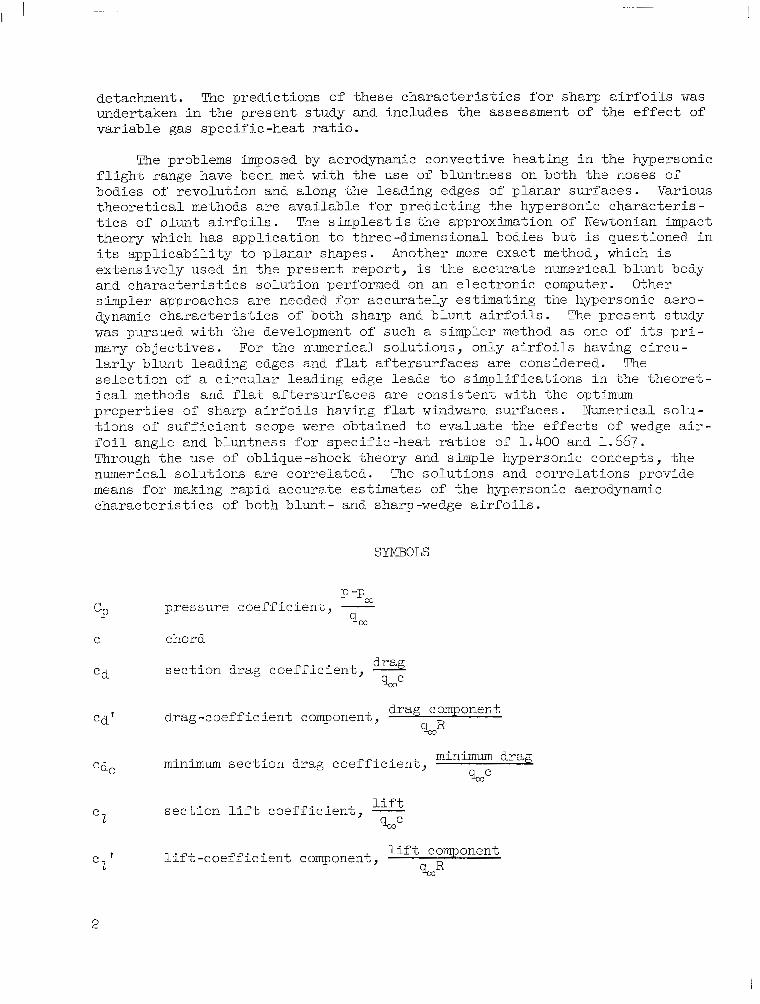
The inviscid hypersonic aerodynamic character is t ics of c i rcular ly blunt- wedge a i r f o i l s a r e d e r i v e d from numerical solutions. Hy-personic wedge theory based on explicit oblique-shock equations i s shown to provide rapid es t imates of the pressures over both sharp and b l u n t a i r f o i l s . The effects of varying t h e a i r f o i l wedge angle and bluntness and of varying the gas specific-heat r a t io a r e eva lua ted .
The hypersonic wedge theory provides an accurate predict ion of the con- d i t i ons a t shock detachment for sharp a i r foi ls for any value of gas specif ic- hea t r a t io . For the l imi t ing case o f in f in i te Mach number and a spec i f ic -hea t r a t i o of unity, the theory i s i n agreement with Newtonian impact theory. The exact m a x i m u m l i f t - d r a g r a t i o s and the l i f t coe f f i c i en t s a t maximum l i f t - d r a g r a t i o f o r s h a r p a i r f o i l s a t i n f i n i t e Mach number a r e shown.
Variation of gas specif ic-heat ra t io i s shown t o have large effects on the aerodynamic characterist ics of b lun t and s h a r p a i r f o i l s a t hypersonic Mach numbers. The l i f t curves are demonstrated to be highly nonlinear and t o depa r t s ign i f i can t ly from impact theory as the gas spec i f ic -hea t ra t io i s increased.
INTRODUCTION
Both sharp and b lunt a i r fo i l s a re o f in te res t for hypersonic f l igh t . Sharp leading edges are desirable from the standpoint of reducing drag and thereby achieving efficient hypersonic airfoil performance with increased l i f t - t o - d r a g r a t i o s . P r i m a r y i n t e r e s t i n s h a r p a i r f o i l s h a s g e n e r a l l y b e e n d i rec ted to the lower end of the hypersonic speed range where convective heat- ing presents no insurmountable diff icul t ies . Useful techniques for estimat- ing the hypersonic aerodynamic character is t ics of sharp, th in a i r foi ls a t small angles of a t tack were developed i n references 1, 2, and 3 using hyper- son ic s imi l a r i t y l a w s and small-disturbance approximations. One of the s i g n i f i c a n t r e s u l t s t o a r i s e from t h e s e e a r l i e r s t u d i e s i s tha t , wi th in the l imi ted scope of a i r fo i l s and angles of attack covered, the hypersonic a i r - f o i l having a f l a t windward sur face appears to o f fe r the optimum r a t i o of l i f t t o d rag . However, t hese ea r l i e r s tud ie s d id no t cove r t he problem of p r e d i c t i n g a i r f o i l c h a r a c t e r i s t i c s a t larger angles of a t tack up t o shock
detachment. The p r e d i c t i o n s o f t h e s e c h a r a c t e r i s t i c s f o r s h a r p a i r f o i l s was undertaken in t he p re sen t s tudy and includes the assessment of the effect of va r i ab le gas spec i f ic -hea t ra t io .
The problems imposed by aerodynamic convective heating in t he hype r son ic f l i gh t r ange have been met with the use of bluntness on both the noses of bodies of revolution and along the leading edges of planar surfaces. Various t h e o r e t i c a l methods are avai lable for predict ing the hypersonic character is- t i c s o f b l u n t a i r f o i l s . The s implest i s the approximation of Newtonian impact theory which has appl icat ion to three-dimensional bodies but i s quest ioned in i t s app l i cab i l i t y t o p l ana r shapes . Another more exact method, which is extensively used in the present report , i s the accurate numerical b lunt body and cha rac t e r i s t i c s so lu t ion performed on an e l ec t ron ic computer. Other simpler approaches are needed for accurately es t imat ing the hypersonic aero- dynamic c h a r a c t e r i s t i c s of both sharp and b l u n t a i r f o i l s . The present s tudy w a s pursued with the development of such a simpler method as one of i t s p r i - mary object ives . For the numerical solut ions, only a i r foi ls having c i rcu- l a r l y b l u n t l e a d i n g edges and f l a t a f t e r su r faces are considered. The se l ec t ion of a c i r cu la r l ead ing edge h a d s t o s i m p l i f i c a t i o n s i n t h e t h e o r e t - i c a l methods and f l a t a f t e r su r faces are consis tent with the optimum proper t ies o f sharp a i r fo i l s having f l a t windward surfaces. Numerical solu- t ions o f suf f ic ien t scope were obta ined to eva lua te the e f fec ts o f wedge a i r - f o i l a n g l e and b luntness for spec i f ic -hea t ra t ios of 1.400 and 1.667. Through the use of oblique-shock theory and simple hypersonic concepts, the numerical solutions are cor re la ted . The so lu t ions and correlat ions provide means f o r making rapid accurate estimates of the hypersonic aerodynamic c h a r a c t e r i s t i c s of both blunt- and sharp-wedge a i r f o i l s .
SYMBOLS
CP C
Cd
Cd'
CdO
C 2
e ' 2
2
chord
sec t ion drag coef f ic ien t , - drag %me
drag -coeff ic ient component , drag component
minimum sec t ion drag coef f ic ien t , minimum drag n r2
sec t ion l i f t coe f f i c i en t , - lift
%mC
l i f t - c o e f f i c i e n t component, lift component
%mR
Cm
Cn
D
L
M
P
9
R
X
X '
2'
a
Y
6
s, e w
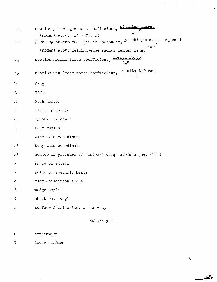
section pitching-moment coefficient, p i tch ing moment
(moment about x' = 0.4 e )
pitching-moment coe f f i c i en t component, pitching-moment component %R2
(moment about leading-edge radius center l ine) _ _
sect ion normal-force coeff ic ient , normal force %ac
sec t ion resu l tan t - force coef f ic ien t , r e su l t an t fo rce %ac
drag
l i f t
Mach number
s t a t i c p r e s s u r e
dynamic pressure
nose radius
wind-axis coordinate
body-axis coordinate
center of pressure of windward wedge surface
angle of a t t a c k
r a t i o of spec i f ic hea ts
f low deflection angle
wedge angle
shock -wave angle
sur face inc l ina t ion , w = a + 6,
Subscripts
D detachment
2 lower surface
le leading edge
m a x m a x i m u m value
03 free stream
s t s tagnat ion
U upper surface
Superscr ipts
aerodynamic parameters obtained from oblique-shock theory
correlation parameters (eqs. (24), (25), (26), and (27) )
A ~ R I C A L BLUNT -WEDGE SOLUTIONS
Method and Results of Numerical Calculations
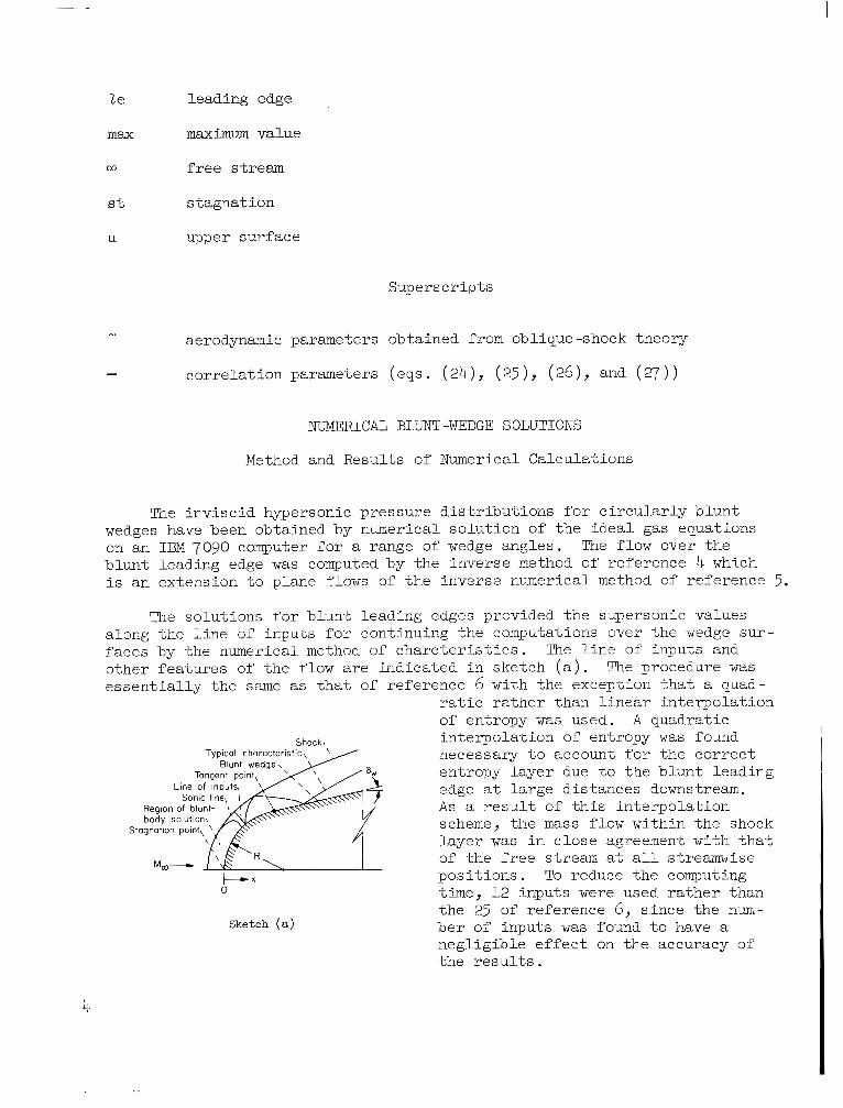
The inv i sc id hype r son ic p re s su re d i s t r ibu t ions fo r c i r cu la r ly b lun t wedges have been obtained by numerical solution of the ideal gas equations on an IBM 7090 computer for a range of wedge angles . The flow over the blunt leading edge w a s computed by the inverse method of reference 4 which i s an extension to plane f lows of the inverse numerical method of reference 5.
The solutions for blunt leading edges provided the supersonic values a long t he l i ne of inputs for continuing the computations over the wedge sur- faces by the numerical method of c h a r c t e r i s t i c s . The l i n e of inputs and o ther fea tures of the f low are ind ica ted in ske tch ( a ) . The procedure w a s e s s e n t i a l l y t h e same as t h a t of reference 6 with the except ion that a quad-
r a t i c r a t h e r t h a n l i n e a r i n t e r p o l a t i o n of entropy w a s used. A quadrat ic
necessary to account for t he co r rec t entropy layer due t o t h e b l u n t l e a d i n g edge a t la rge d i s tances downstream. A s a r e s u l t of t h i s i n t e r p o l a t i o n scheme, t he mass flow within the shock l a y e r w a s i n c l o s e agreement with that of t h e f r e e stream a t a l l streamwise
Shock> interpolat ion of entropy was found
t-. pos i t i ons . To reduce the computing 0 time, 12 inputs were used ra ther than
the 25 of reference 6, s ince the num-
n e g l i g i b l e e f f e c t on the accuracy of t h e r e s u l t s .
Sketch (a ) ber of inputs was found t o have a
4
. .

The so lu t ions were obta ined for as wide a v a r i a t i o n i n wedge angle- .as . . the computing procedure would permit. Solutions were obtained for wedge angles-up t o 30' which were within the range where the f low w a s en t i re ly supersonic over t h e wedge sur face . The absence of solut ions for greater angles i s of l i t t l e concern because a t the higher angles , induced effects of the blunt leading edge are small and surface pressure i s c lose ly p red ic ted by oblique-shock theory. The lower limits of wedge angles of -15' and -5' fo r spec i f i c -hea t r a t i o s of 1.400 and 1.667, respectively, a r e imposed because of inaccuracies in the b lunt -body so lu t ion for inputs near the body.
Pressure dis t r ibut ions over blunt leading edges. - The ef fec ts o f spec i f i c - h e a t r a t i o on the p re s su re d i s t r ibu t ion of the leading edge a r e shown i n f i g - ure 1. Since charac te r i s t ic so lu t ions could not be obtained for a spec i f i c - h e a t r a t i o of 1 .0 a t Mach numbers of 10 and a, only the subsonic blunt leading- edge p a r t of the so lu t ion i s shown i n f igu re l ( a ) . The pres su re d i s t r ibu t ion f o r y of 1 .0 and i n f i n i t e Mach number ( f i g . l ( b ) ) w a s obtained by the Newton- Busemann pressure l a w (Newtonian plus cent r i fuga l force cor rec t ion) g iven in reference 3 and under these conditions i s an exact solut ion. For s p e c i f i c - hea t r a t io s of 1.400 and 1.667, the cha rac t e r i s t i c s pa r t of the so lu t ion beg ins s l i gh t ly a f t e r t he son ic po in t a t x/R 0 .3 and continues to x/R = 1.0. The shape of the solution for y of 1.667 sugges ts s l igh t inaccurac ies in the blunt-body solution which are adjusted as the cha rac t e r i s t i c so lu t ion proceeds. The e f fec t o f spec i f ic -hea t r a t i o f o r t h e r a n g e from 1.200 t o 1.667 i s small. Although no t shown, modified Newtonian theory, Cp = Cp s in2 6, c lose ly p red ic t s t he p re s su re d i s t r ibu - t ion over the forward par t of the nose (x/R -? 0.4), but se r ious ly underes t i - mates the p ressures over the a f te rpar t (x/R 9 0 . 4 ) . For these p ressures re f - erence 7 gives a be t t e r e s t ima te which consis ts in matching pressure gradients obtained from modified Newtonian theory and a Prandt l "eyer expansion.
s t
0 2 4 .6 .e 1.0 x/R
(a) M, = 10
2.0 R I 000 Y
"- ""
I 200 I 400 I 6 6 7 _""" 1.6b 1.2 \
CP
8
4
0
(b) % =
Figure 1.- Pressure d i s t r ibu t ion over the blunt l ead ing edge.
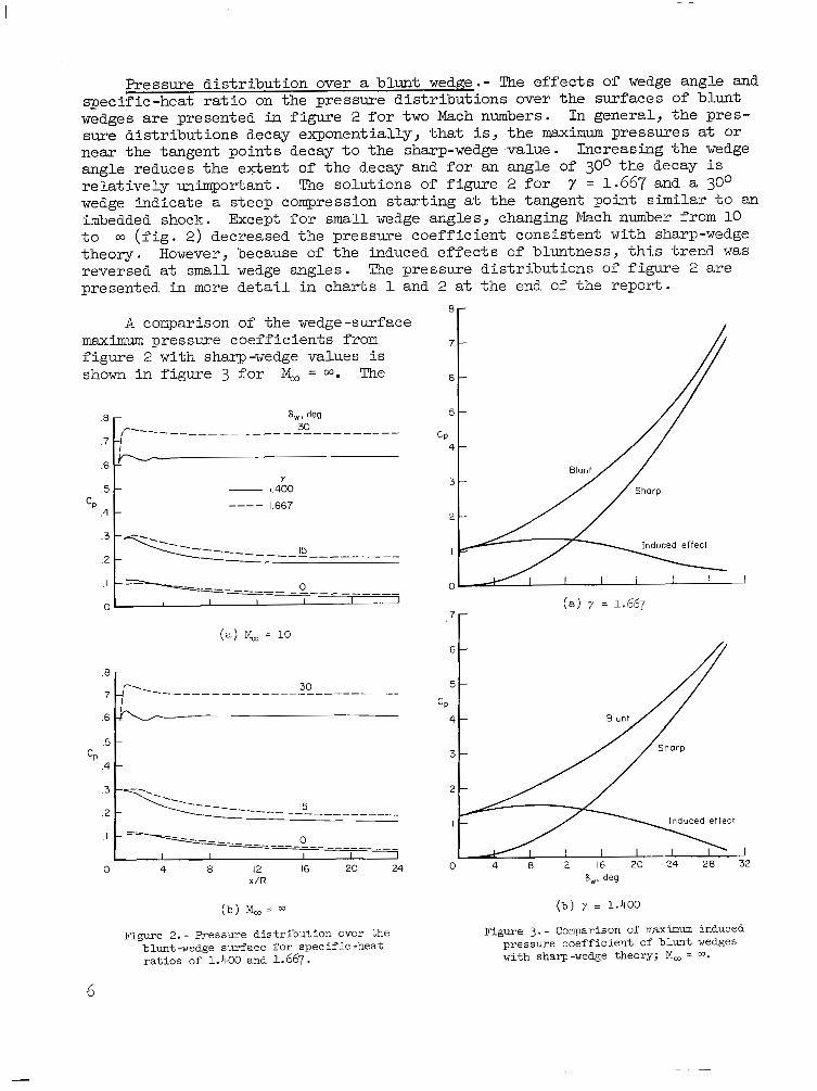
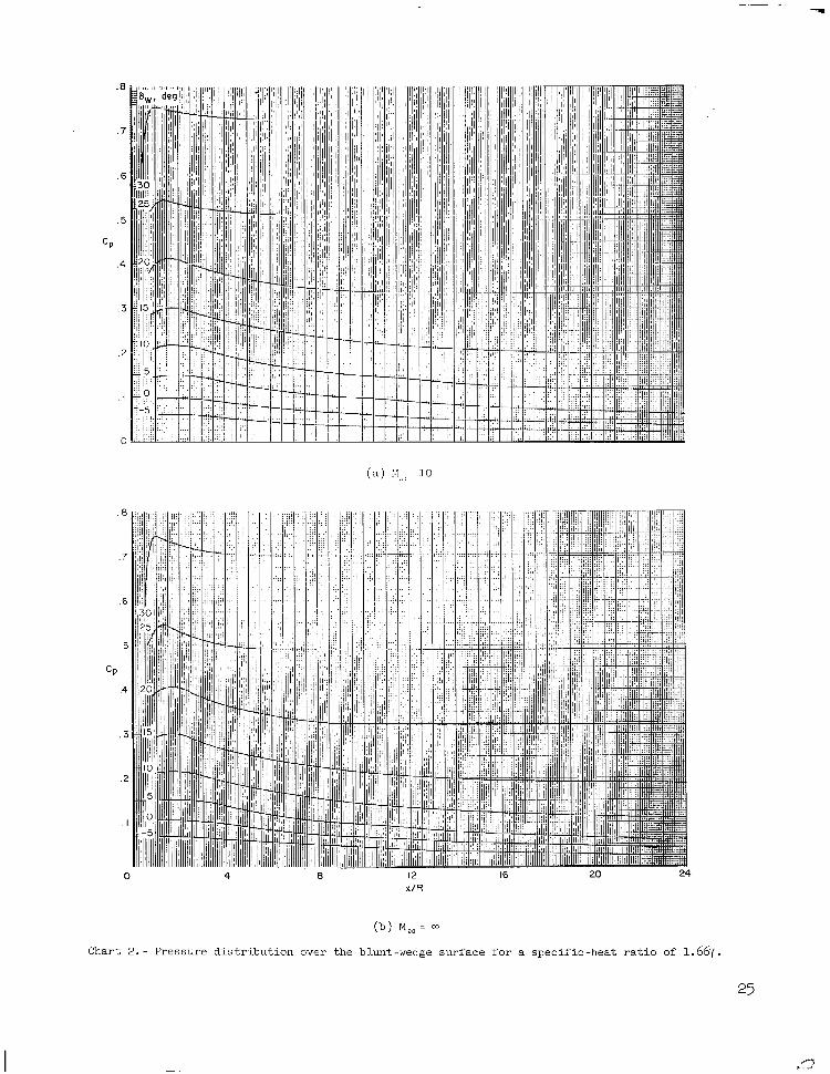
Pressure dis t r ibut ion over a blunt wedge .- The e f fec t s o f wedge angle and spec i f ic -hea t ra t io on the p ressure d i s t r ibu t ions over the sur faces of blunt wedges are presented in figure 2 f o r two Mach numbers. I n genera l , the p res - sure d is t r ibu t ions decay exponent ia l ly , tha t is, the maximum pressures at or near the tangent points decay to the sharp-wedge value. Increasing the wedge angle reduces the extent of the decay and f o r an angle of 30° the decay i s relat ively unimportant . The so lu t ions of figure 2 f o r y = 1.667 and a 30° wedge indica te a s teep compression s tar t ing at the tangent point similar t o an imbedded shock. Except f o r small wedge angles, changing Mach number from 10 t o 03 ( f i g . 2) decreased the pressure coeff ic ient consis tent with sharp-wedge theory. However, because of t h e induced effects of b lun tness , t h i s t r end was reversed a t small wedge angles . The pressure d i s t r ibu t ions of f igu re 2 a r e presented in more detai l i n c h a r t s 1 and 2 a t t h e end of t he r epor t .
8 -
A comparison of the wedge-surface maximm pressure coeff ic ients from 7 -
f igu re 2 with sharp -wedge values is shown i n f i g u r e 3 f o r M, = w. The 6 -
8 - 8,. deg 5 - ,""- ""_"""""_"""~ 30
.7 -I I
.6 - !
.5 - - 1.400
.4 - 1.667
CP 4 -
Y 3 -
CP ""
""""-!?""""-
.I """""" 0
I
0 I I I I I J
.7r (a) M, = 10
0 --- ""~""""_""_ I I I
0 4 8 12 16 20 24 x / R
Induced effect
( b ) M, = ( b ) 7 1.400
Figure 2. - h-essure d i s t r ibu t ion over t h e blunt-wedge surface for specif ic -heat r a t i o s of 1.400 and 1.667.
Figure 3. - Comparison of maximum induced pressure coef f ic ien t o f b lunt wedges with sharp-wedge theory; M, = m.
6
magnitude and r e l a t i v e importance of the induced effects of bluntness-razg- indicated by the d i f fe rence between the maximum pressure coef f ic ien ts -oTpt,he blunt and sharp wedges. It is apparent that induced effects are relatively unimportant f o r large wedge angles . For wedge angles less than about 2 6 O , induced e f fec ts a re s l igh t ly less for 7 of 1.667 than for ' 1.400.
ALRFOIL-SECTION CHARAC'ITERISTICS
The p res su re d i s t r ibu t ions fo r t he b lun t wedges have been integrated graphical ly t o provide the cont r ibu t ions to l i f t , drag, and pitching-moment coe f f i c i en t s of the leading-edge and wedge sur faces . A method w i l l be developed f o r eva lua t ing charac te r i s t ics of b l u n t a i r f o i l s at angle of at tack by the superposi t ion of t h e blunt-wedge solutions separately obtained f o r t h e upper and lower surfaces.
Superposition of Blunt-Wedge Solutions
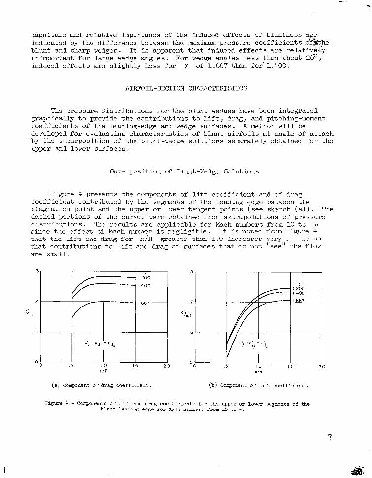
Figure 4 presents the components of li.ft coef f ic ien t and of drag coeff ic ient contr ibuted by t h e segments of the leading edge between the stagnation point and the upper or lower tangent points (see sketch ( a ) ) . The dashed portions of the curves were obtained from extrapolations of pressure d i s t r i b u t i o n s . The r e su l t s a r e app l i cab le f o r Mach numbers from 10 t o w s ince the e f fec t of Mach number i s negl ig ib le . It i s noted from figure 4 t h a t t h e lift and drag f o r x/R greater than 1.0 i n c r e a s e s v e r y l i t t l e SO
that contr ibut ions t o l i f t and drag of surfaces that do not "see" the flow are small.
7' . . - I I "
1.260
1.400
.5 x / R 1.0 1.5
(a) Component o f d rag coe f f i c i en t
.5 i .5 I x/R 1.0
I
i I. 200
1.667
I I 1.5
(b) Component of l i f t c o e f f i c i e n t .
Figure 4.- Components of l i f t and drag coeff ic ients for the upper or lower segments of the blunt leading edge for Mach numbers from 10 t o a.
7
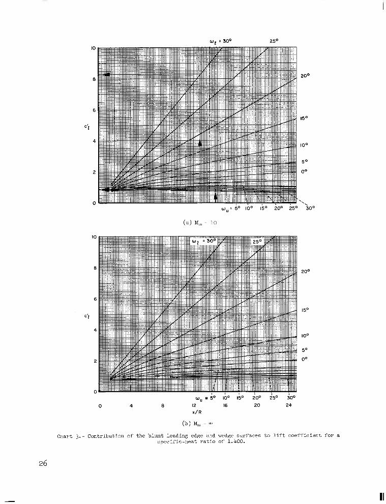
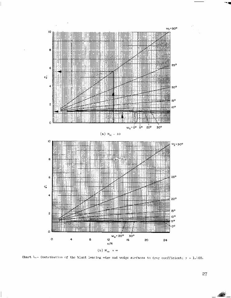
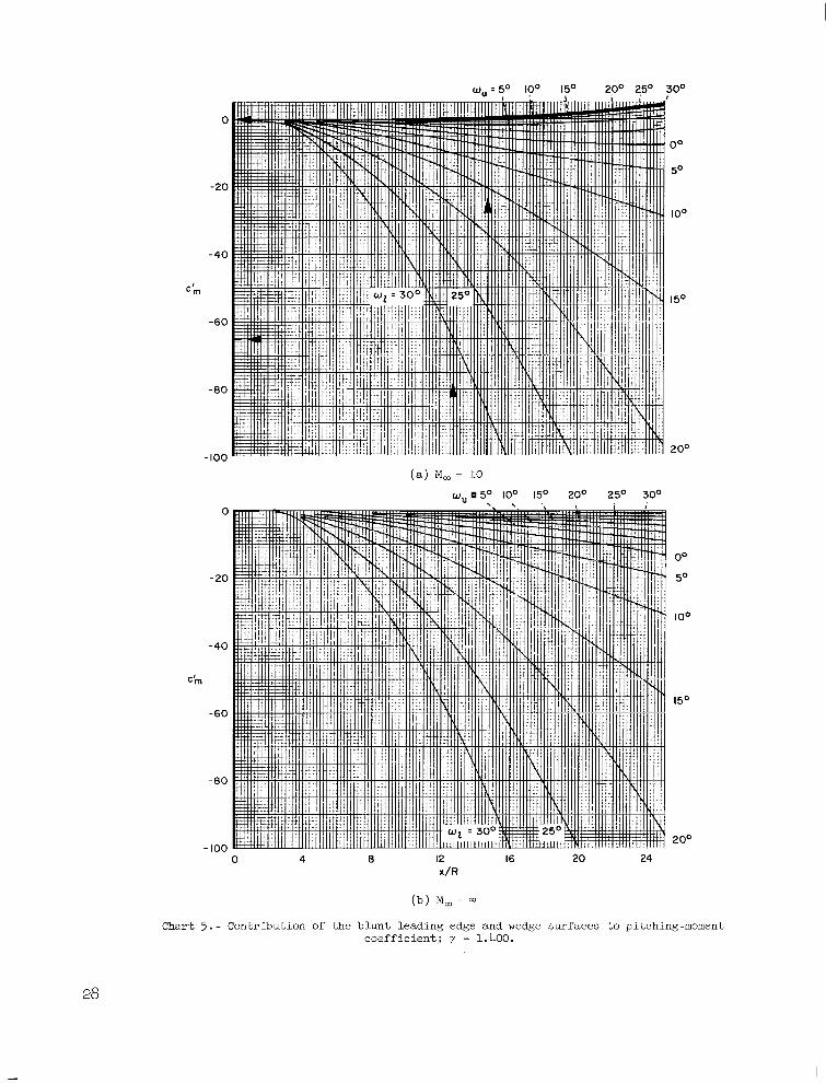
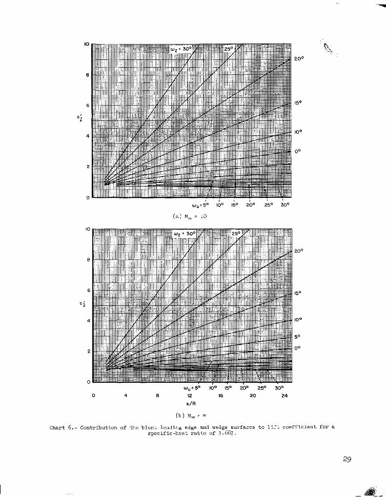
The respect ive contr ibut ions of the leading-edge and wedge surfaces have been combined t o provide universal char ts from which inv isc id l i f t , drag, and pitching-moment coe f f i c i en t s of c i r c u l a r l y blunt-wedge airfoils can be easily evaluated. These r e s u l t s are presented in cha r t s 3 through 8 f o r s p e c i f i c - heat ratios of 1.400 and 1.667. For upper-surface inclinations greater than 150 ( y = 1.400) and grea te r than 5' (7 = 1.667) the curves of t he cha r t s were obtained from extrapolations of pressure d i s t r ibu t ions as previously noted. Since the pressure coefficient i s rapidly approaching the l imit ing value, - 2 / y G 2 , with increasing upper-surface inciination, the need f o r extrapola- t ions diminishes with increasing angles of a t tack.
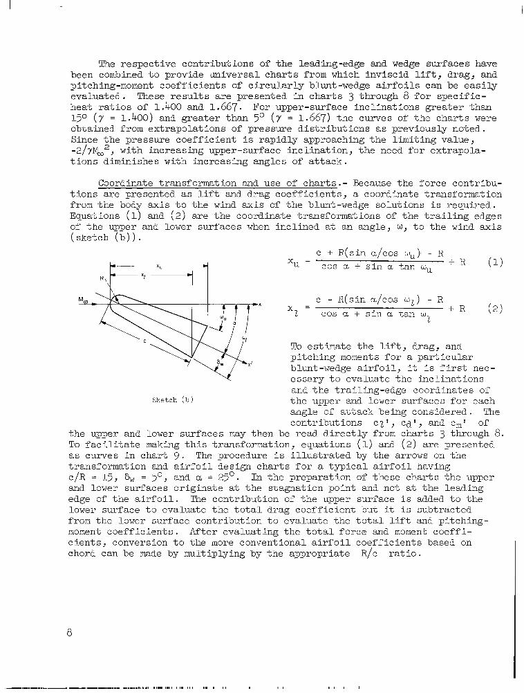
Coordinate transformation and use of cha r t s . - Because the force contr ibu- t ions a re p resented as l i f t and drag coef f ic ien ts , a coordinate transformation from t h e body a x i s t o t h e wind a x i s of t h e blunt-wedge solutions i s required. Equations (1) and (2 ) are the coordinate t ransformations of t h e t r a i l i n g edges of the upper and lower surfaces when incl ined a t an angle, w, t o t h e wind a x i s (sketch ( b ) ) .
c + R( s i n a/cos %). - R = cos a + s i n a t a n mu + R (1)
c - R(sin a/cos w z ) - R x = 2 cos a + s i n a tan w + R (2)
2
To e s t imate the l i f t , drag, and p i tch ing moments f o r a p a r t i c u l a r blunt-wedge a i r f o i l , it i s f i rs t nec- essary t o evaluate the incl inat ions and the t ra i l ing-edge coordinates of
angle of a t tack being considered. The cont r ibu t ions cz l , e a ' , and em1 of
Sketch (b) the upper and lower surfaces for each
t h e upper and lower surfaces may then be r ead d i r ec t ly from cha r t s 3 through 8. To f a c i l i t a t e making this t ransformation, equat ions (1) and (2) are presented as curves in char t 9 . The procedure i s i l l u s t r a t e d by the arrows on the transformation and a i r f o i l d e s i g n c h a r t s f o r a t y p i c a l a i r fo i l having c/R = 15 , S, = 5' , and a, = 25'. In the p repara t ion of these char ts the upper and lower surfaces originate a t the s tagnat ion point and not a t the leading edge of t h e a i r f o i l . The contriblJLion of t h e upper surface i s added t o t h e lower surface t o e v a l u a t e t h e t o t a l d r a g c o e f f i c i e n t b u t it i s subtracted from the lower surface contribution to evaluate the t o t a l l i f t and pi tching- moment coe f f i c i en t s . Af t e r eva lua t ing t he t o t a l fo rce and moment coe f f i - cients, conversion t o the more conventional a i r f o i l coeff ic ients based on chord can be made by multiplying by the appropriate R/c r a t i o .
8

Effec ts of A i r f o i l Geometry
Two pa rame te r s t ha t de f ine t he p ro f i l e o f c i r cu la r ly b lun t a i r fo i l s a r e the b luntness ra t io , R/c, and the wedge angles, h, of the upper and the lower surfaces with respect to the body or reference axis. Since var ia t ions of ei ther parameter may have important effects on aerodynamic cha rac t e r i s - t i cs , the e f fec ts o f vary ing each w i l l be considered separately. Only the symmetrical a i r f o i l w i l l be considered, since it i s apparent the effect of asymmetry can be accounted fo r by a sh i f t i n r e f e rence ang le of a t t ack . A base p ressure coef f ic ien t of zero w i l l be assumed.
Effect of wedge angle . - Figure 5 presents the e f fec t of wedge angle on the l i f t , drag, and pitching-moment coe f f i c i en t s and l i f t - d r a g r a t i o of b lun t a i r fo i l s hav ing a bluntness , R/c, of 0.05. A t hypersonic Mach numbers, it i s evident from f igu re 5 t h a t increasing the wedge angle i s an e f fec - t i v e means f o r i n c r e a s i n g l i f t -curve s lope o f b lunt a i r fo i l s wi th in the angle-of-attack range shown. It may be observed that the ,lift curve of the b l u n t a i r f o i l of 0 wedge angle i s wel l approximated by oblique -shock f l a t - pla te theory a t the higher angles of a t t ack . Although increasing wedge angle increased the drag coeff ic ient , the m a x i m u m va lue o f l i f t -drag ra t io w a s pract ical ly unaffected because of the accompanying increase in l i f t c o e f f i - c i e n t ; however, the angle of a t t a c k f o r m a x i m u m l i f t - d r a g r a t i o was reduced. For a given angle of a t tack, p i tching- moment coef f ic ien t increased wi th wedge angle. Because of a corresponding increase in l i f t coe f f i c i en t , however, increasing the wedge angle increased t h e s t a t i c l o n g i t u d i n a l s t a b i l i t y , - ( dcm/dc ) , only s l igh t ly .
Ef fec t of varying bluntness.- Leading-edge bluntness may be considered to exer t th ree in f luences on the aero- dynamic c h a r a c t e r i s t i c s of wedge a i r - f o i l s . F i r s t , t h e p r e s s u r e s on the leading edge differ from those of a s h a r p a i r f o i l and ef fec t ive ly cause concentrated forces a t the leading edge. Second, bluntness has a carry-over or
.6
5
4
3 CZ
2
I
0
2 4 \
Flat plate, L / D :cot w------‘\ \
\
.5
4
cd I
‘r
0 4 8 12 16 20 24 28 32 36 40 a , deg
(a ) M, = 10, y = 1.400
Figure 5 . - Ef fec t of varying wedge angle on t h e aerodynamic cha rac t e r i s t i c s o f blunt a i r f o i l s ; R/c = 0.05.
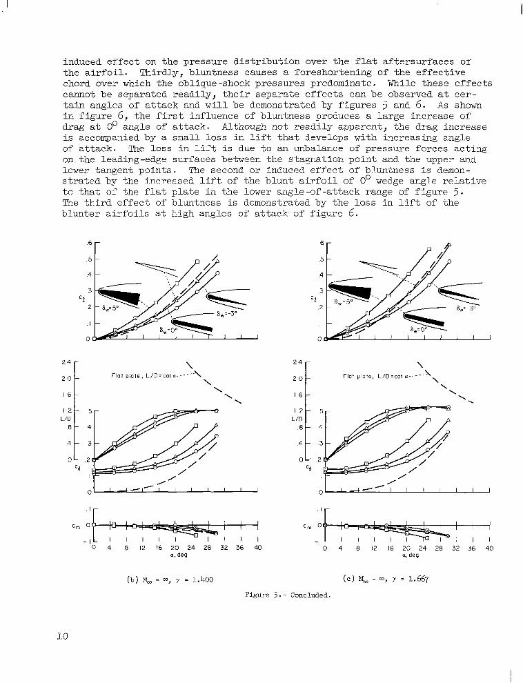
induced effect on the p ressure d i s t r ibu t ion over the f l a t a f t e r su r faces or the a i r foi l . Thirdly, b luntness causes a foreshor ten ing of the e f fec t ive chord over which the oblique-shock pressures predominate. While these effects cannot be separated readi ly , their separate effects can be observed a t c e r - ta in angles of a t t ack and w i l l be demonstrated by figures 5 and 6. A s shown i n f i g u r e 6, t he f i rs t influence of bluntness produces a large increase of drag a t 0' angle of attack. Although not readily apparent, the drag increase is accompanied by a small loss i n l i f t t h a t develops with increasing angle of a t tack. The loss i n l i f t is due to an unbalance of pressure forces acting on the leading-edge surfaces between the stagnation point and the upper and lower tangent points. The second or induced effect of bluntness i s demon- s t r a t e d b y t h e i n c r e a s e d l i f t of t h e b l u n t a i r f o i l of 0' wedge ang le r e l a t ive t o t h a t o f the f la t p la te in the lower angle-of -a t tack range of f igu re 5 . The t h i r d e f f e c t of bluntness is demonstrated by the loss i n l i f t of t he b l u n t e r a i r f o i l s a t high angles of a t tack- of f i gu re 6.
c Z
5
4
'd I
' r
0 4 8 12 16 20 24 28 32 36 40 a , deg
(b) M, = m, y = 1.400
\ \ '.
~
5
4
'd I
0 4 8 I2 16 20 24 28 32 36 40 a, deg
Figure 5 . - Concluded.
10
/ / P
j / i 8 4 0
\
1 Sbarp wedge, L/D=cot(a+8,,,)->~
\ \ '.
/ /
cd
.6 r
.5 -
2 o r I \
L : i i 4 8 0 'd
I Sharp wedge, L / D = c 0 l ( a t 8 ~ ) - ~ \
I ,' \
/ /
/
- 1 I I 0 4 8 12 16 20 24 28 32 36 40 0 4 8 12 16 20 24 28 32 36 40
r , I I I
(a) M, = m, y = 1.400 (b) M, = m, 7 = 1.667
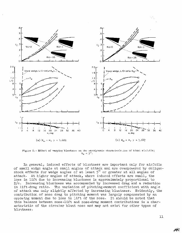
Figure 6.- Effect of varying bluntness on the aerodynamic characteristics of blunt airfoils; = 50.
In general , induced effects of b luntness a re impor tan t on ly for a i r fo i l s of small wedge angle a t small angles of attack and are overpowered by oblique- shock e f f e c t s f o r wedge angles of a t l e a s t 5' or g rea t e r a t a l l angles of a t t ack . A t higher angles of attack, where induced e f f e c t s a r e small, the loss i n l i f t due to increas ing b luntness i s approximately proportional to R/c. Increasing bluntness was accompanied by increased drag and a reduction i n l i f t - d r a g r a t i o . The variation of pitching-moment coefficient with angle of a t t ack w a s only s l ight ly affected by increasing bluntness . Evident ly , the contr ibut ion of nose drag t o p i t c h i n g moment w a s l a rge ly compensated by an opposing moment due -to loss i n L i f t of the nose. It should be noted that this balance between nose-lift and nose-drag moment contr ibut ions i s a char- a c t e r i s t i c of the c i rcular blunt nose and may not ex is t for o ther types of bluntness .
11
Effect of Mach number and specif ic-heat ra t io . - Figures 5 (a ) and 5 ( b ) ind ica te tha t increas ing Mach numbers from 10 t o a reduced the lift and drag , b u t l e f t m a x i m u m l i f t -drag r a t io abou t t he same. Increasing specif ic - h e a t r a t i o from 1.400 t o 1.667 ( f i g s . 5 (b ) and 5 ( e ) ) increased the l i f t and m a x i m u m l i f t - d r a g r a t i o . S i m i l a r e f f e c t s due to i nc reas ing t he spec i f i c - h e a t r a t i o a r e e v i d e n t i n f i g u r e s 6(a) and 6 ( b ) f o r a n a i r f o i l whose b lun t - ness is 0.10. Figures 5 and 6 also demonstrate that increasing the spec i f i c -hea t r a t io i nc reased t he pitching-moment coeff ic ient , but because o f t he i nc rease i n l i f t c o e f f i c i e n t , t h e s t a t i c s t a b i l i t y , -(dCm/dCL), i s re la t ively unaffected. In conclusion, it has been demonstrated that induced effects of bluntness are important mainly a t low angles of a t tack. A t high angles of attack, oblique-shock theory of sharp-wedge airfoils correctly p r e d i c t s f o r c i r c u l a r l y b l u n t a i r f o i l s t h e t r e n d s o f l i f t coef f ic ien t p ro- duced by increasing wedge angle, Mach number, and specif ic-heat ra t io . Because of i t s gene ra l su i t ab i l i t y fo r p red ic t ing t hese t r ends , ob l ique - shock theory w i l l be examined next with the intention of developing a simple approximation that accurately predicts blunt a i r foi l character is t ics a t hypersonic Mach numbers.
HYPERSONIC WEDGE TKFORY
Derivation and Application
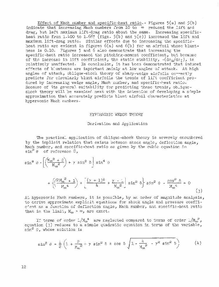
The pract ical appl icat ion of obl ique-shock theory i s severely encumbered by t he imp l i c i t r e l a t ion t ha t ex i s t s between shock angle, deflection angle, Mach number, and spec i f ic -hea t ra t io as given by the cubic equation in s in2 e of reference 8 ,
A t hypersonic Mach numbers, it i s possible, by an order of magnitude analysis , to der ive approximate expl ic i t equat ions for shock angle and pressure coeff i - c i e n t as a funct ion of def lect ion angle , Mach number, and spec i f ic -hea t ra t io t h a t i n the limit, M, = a, are exact .
If term of order l /Ma4 are neglected compared t o terms of order l/Ma2, equation ( 3 ) reduces to a simple quadratic equation in terms of the variable, s in2 8 , whose so lu t ion is
12
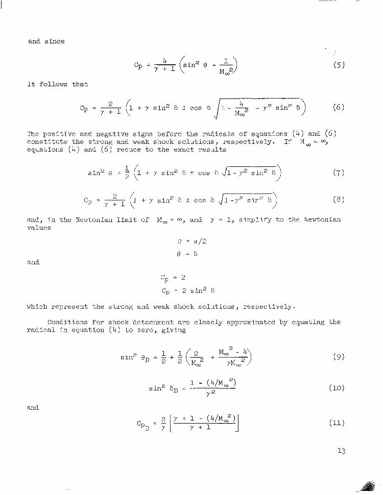
and since
" s in2 e - -) 1 cp = - Y + 1 M co2
it follows t h a t
The pos i t i ve and negat ive s igns before the radicals of equations ( 4 ) and ( 6 ) cons t i t u t e the s t rong and weak shock solutions, respectively. If Ma, = 00, equations ( 4 ) and ( 6 ) reduce t o t h e e x a c t r e s u l t s
and, i n t h e Newtonian limit of M, = 03, and y = 1, s impl i fy t o t he Newtonian values
and
% = 2
cP = 2 s i n 2 6
which represent the s t rong and weak shock solut ions, respect ively.
Conditions for shock detachment are c lose ly approximated by equating the r ad ica l i n equa t ion ( 4 ) to zero , g iv ing
and
For i n f i n i t e Mach number, exact detach- ment condi t ions are
80 -
70 -
60 -
50 -
Hypersonlc-wedge theory (eq.(411 Obhque-shock theory (Ref 81
I I I I I I 0 IO 20 30 40 50 60
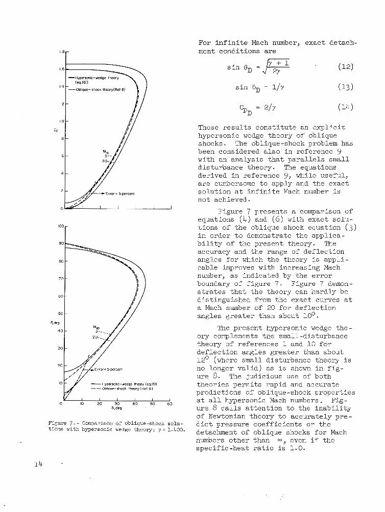
Figure 7. - Comparison of oblique-shock solu- t ions with hypersonic wedge theory; r = 1.400.
c p D = 2lY
These r e s u l t s c o n s t i t u t e a n e x p l i c i t hypersonic wedge theory of oblique shocks. The oblique-shock problem has been considered a lso in reference 9 wi th an ana lys i s t ha t pa ra l l e l s small dis turbance theory. The equations der ived in re fe rence 9, while useful, are cumbersome t o a p p l y and the exac t so lu t ion a t i n f i n i t e Mach number i s not achieved.
Figure 7 presents a comparison of equations ( 4 ) and ( 6 ) with exact so lu- t ions of the oblique shock equation ( 3 ) in o rder to demonst ra te the appl ica- b i l i t y of the present theory. The accuracy and the range of deflection angles for which the theory is a p p l i - cable improves with increasing Mach number, as ind ica ted by t h e e r r o r boundary of f i gu re 7 . Figure 7 demon- strates tha t the theory can hard ly be d is t inguished from the exact curves a t a Mach number of 20 f o r d e f l e c t i o n angles greater than about 10'.
The present hypersonic wedge the- ory complements the small-dis turbance theory of references 1 and 10 f o r def lect ion angles greater than about 12' (where small disturbance theory i s no longe r va l id ) as i s shown i n f i g - ure 8. The judicious use of both theor ies permi ts rap id and accurate pred ic t ions of oblique-shock properties a t a l l hypersonic Mach numbers. Fig- ure 8 c a l l s a t t e n t i o n t o t h e i n a b i l i t y of Newtonian theo ry t o accu ra t e ly p re - d i c t p r e s s u r e c o e f f i c i e n t s or the detachment of oblique shocks f o r Mach numbers o ther than m, even i f t he spec i f i c -hea t r a t io i s 1 .0 .
14
/<-Newtonian
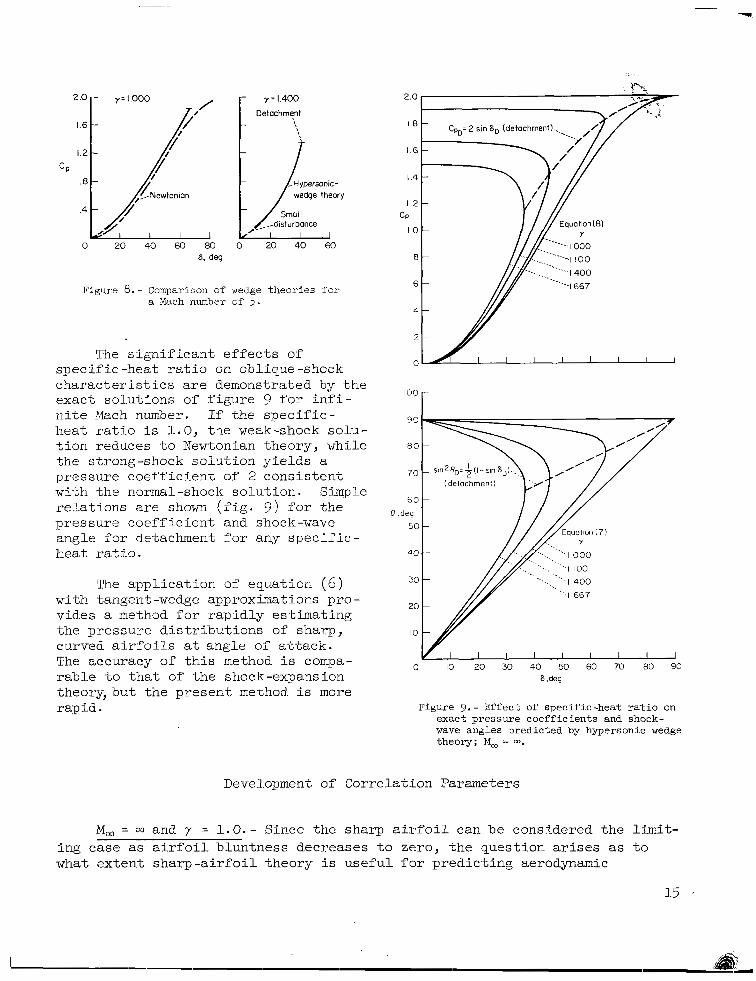
Figure 8 . - Comparison of wedge t h e o r i e s f o r a Mach number of 5 .
The s ign i f i can t e f f ec t s o f spec i f i c -heat r a t i o on oblique-shock c h a r a c t e r i s t i c s are demonstrated by t h e exact solut ions of f igure 9 f o r i n f i - n i t e Mach number. If the spec i f i c - h e a t r a t i o i s 1.0, t he weak-shock so lu- t i on r educes t o Newtonian theory, while the s t rong-shock solut ion yields a pressure coef f ic ien t of 2 cons is ten t with the normal-shock solution. Simple r e l a t ions a r e shown ( f i g . 9 ) f o r t h e pressure coef f ic ien t a.nd shock-wave angle for detachment f o r any s p e c i f i c - heat r a t i o .
The appl icat ion of equat ion ( 6 ) with tangent -wedge approximations pro - vides a method fo r r ap id ly e s t ima t ing the p re s su re d i s t r ibu t ions of sharp, cu rved a i r fo i l s a t angle of a t tack. The accuracy of t h i s method i s compa- rable t o t h a t of the shock-expansion theory,but the present method i s more r ap i d .
2.0
18
1.6
I .4
1 2 CP
I O
8
6
a
2
0
I O 0
90
80
70
60
8 .deg
50
4 0
30
20
IO
0 I I I I I I I I I
IO 20 30 40 50 60 70 80 90 .deg
Figure 9.- Ef fec t of s p e c i f i c - h e a t r a t i o on exact pressure coefficients and shock- wave angles predicted by hypersonic wedge theory; M, = m.
Development of Correlation Parameters
M, = w and y = 1.0. - Since the sharp a i r foi l can be considered the l imit- ing case as a i r fo i l b lun tness dec reases t o ze ro , t he ques t ion arises as t o what ex ten t sharp-a i r fo i l theory i s u s e f u l f o r p r e d i c t i n g aerodynamic
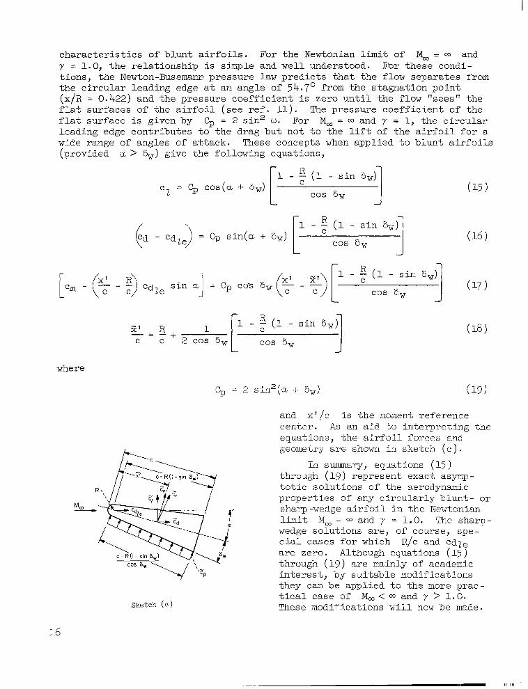
cha rac t e r i s t i c s o f b lun t a i r fo i l s . Fo r t he Newtonian limit of M, = 00 and y = 1.0, the r e l a t ionsh ip is simple and well understood. For these condi- t ions , the Newton-Busemann pressure l a w pred ic t s tha t the f low separa tes from the c i rcu lar l ead ing edge a t an angle of 54.7' from the s tagnat ion po in t (x/R = 0.422) and the pressure coeff ic ient i s zero un t i l the f low "sees" the f l a t s u r f a c e s o f t h e a i r f o i l ( s e e r e f . 11). The pressure coeff ic ient of the f l a t surface i s given by $ = 2 sin" w. For M, = 00 and y = 1, t h e c i r c u l a r leading edge c o n t r i b u t e s t o t h e d r a g b u t n o t t o t h e l i f t of t h e a i r f o i l f o r a wide range of angles of a t t ack . These concepts when a p p l i e d t o b l u n t a i r f o i l s (provided CL > %) give the following equations,
(1 - s i n 6,) c = Gp cos(u + 6,) 2 cos 6w 1
L J
1 - ; (1 - s i n 6,) R EI' R "
c c 2 cos 6, cos 6, - - +
L J
where
cp = 2 s i n 2 ( a + 6,)
and x ' /c i s the moment reference center . A s an a id t o i n t e rp re t ing t he equa t ions , t he a i r fo i l f o rces and geometry a r e shown in ske t ch ( c ) .
In summary, equations (15 ) through (19) represent exact asymp- to t i c so lu t ions o f t he aerodynamic propert ies of any c i rcular ly blunt- or sharp-wedge a i r f o i l i n the Newtonian limit M, = and y = 1.0. The sharp- wedge solutions are, of course, spe- c i a l c a s e s f o r which R/c and CdLe are zero. Although equations (15) through ( 1 9 ) are mainly of academic in te res t , by su i tab le modi f ica t ions they can be applied to the more prac- t i ca l ca se o f M, < a and y > 1.0. These modifications w i l l now be made. Sketch ( e )
16
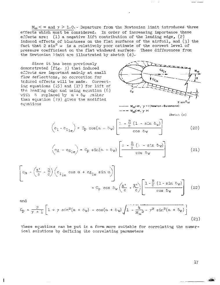
M, < 03 and y > 1.0. - Departure from the Newtonian limit introduces: three e f f e c t s which must be considered. In order of increasing importance these e f f ec t s a r e : (1) a negative l i f t cont r ibu t ion of the leading edge, ( 2 ) induced effects of bluntness on the f l a t surfaces of t h e a i r f o i l , and ( 3 ) the f a c t t h a t 2 s i n 2 w i s a re la t ive ly poor es t imate of t he co r rec t l eve l o f pressure coef f ic ien t on the f l a t windward surface. These differences from the Newtonian l i m i t are i l l u s t r a t e d by sketch (d).
Since it has been previously demonstrated (fig. 3 ) t h a t induced effects are important mainly a t small f low def lect ions, no co r rec t ion fo r induced effects w i l l be made. Correct- ing equations (15 ) and (17 ) for l i f t of the leading edge and using equation ( 6 ) with 6 replaced by a + 6w r a t h e r than equation (19) gives the modified equations 2 s l n 2 w
- Mco=co, y = l (Newton-Busemann) "- Mao<rn, y >I
Sketch ( a )
and
These equations can be put in a form more s u i t a b l e for cor re l a t ing t he numer- i c a l s o l u t i o n s by def ining the correlat ing parameters
I
and - cp cp cos (a + &) (a?
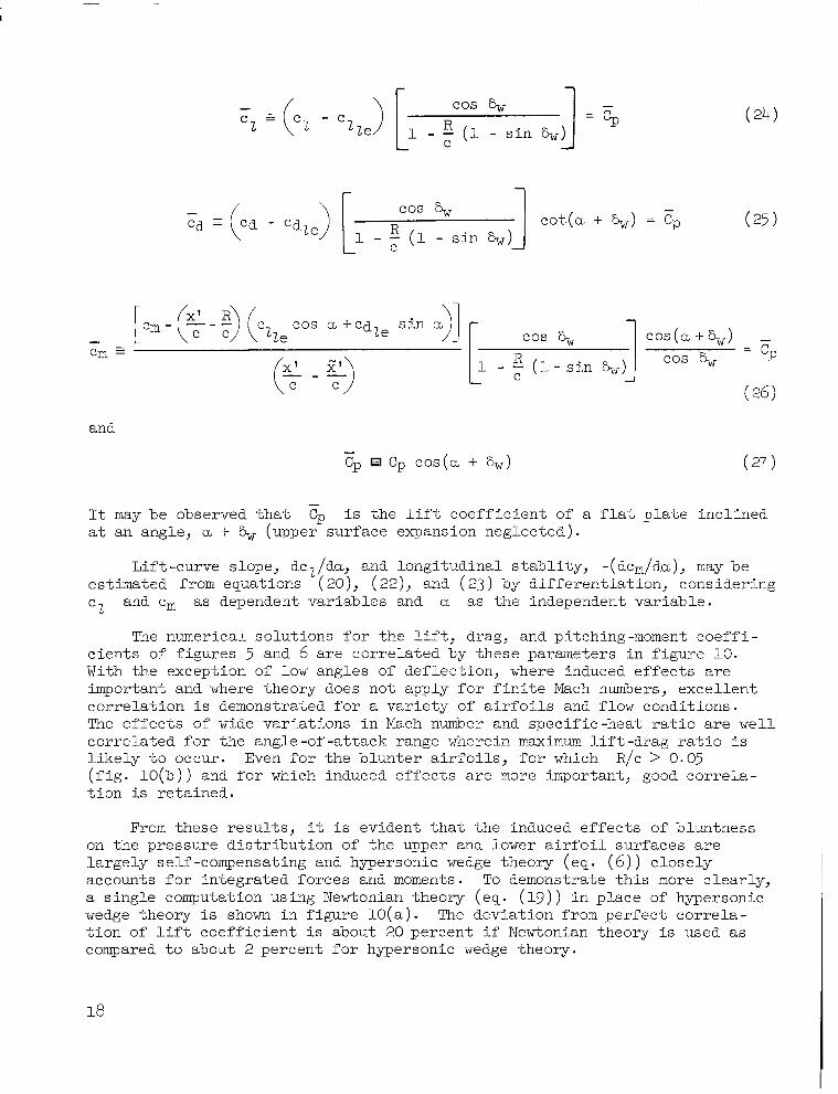
It may be observed that Cp i s the lift coef f ic ien t o f a f l a t p l a t e i n c l i n e d a t an angle, a + S, (upper surface expansion neglected).
-
Lift-curve slope, dcl/da, and longitudinal stabli ty, - ( dCm/da), may be estimated from equations (20), ( 2 2 ) , and (23) by different ia t ion, consider ing e l and em as dependent variables and a as the independent variable.
The numerical solutions for the l i f t , drag, and pitching-moment c o e f f i - c i en t s of f igures 5 and 6 are co r re l a t ed by these parameters in f igure 10. With the exception of low angles of def lect ion, where induced e f f e c t s are important and where theory does no t apply for f in i te Mach numbers, exce l l en t co r re l a t ion i s demonstrated for a v a r i e t y of a i r f o i l s and flow conditions. The ef fec ts o f wide v a r i a t i o n s i n Mach number and s p e c i f i c - h e a t r a t i o are wel l correlated for the angle-of-at tack range wherein m a x i m u m l i f t - d r a g r a t i o i s l i k e l y t o o c c u r . Even f o r t h e b l u n t e r a i r f o i l s , f o r which R/c > 0.05 ( f i g . 1 0 ( b ) ) and f o r which induced e f f e c t s a r e more important, good co r re l a - t i o n i s re ta ined .
From these r e su l t s , it i s ev ident tha t the induced e f fec ts of bluntness on the pressure dis t r ibut ion of the upper and lower a i r f o i l s u r f a c e s are largely self-compensating and hypersonic wedge theory (eq. ( 6 ) ) c lose ly accounts for integrated forces and moments. To demonstrate this more c lear ly , a single computation using Newtonian theory (eq. (19 ) ) i n p l a c e of hypersonic wedge theory i s shown i n figure lO(a). The devia t ion from pe r fec t co r re l a - t i o n of lift coe f f i c i en t is about 20 percent i f Newtonian theory is used as compared t o a b o u t 2 percent for hypersonic wedge theory.
18

.6
.5
.4
F? .3
. 2
.I
t $'"b t 1.400 Y
1.667 1.400 1.667
.6
. 5
.4
.2
.I
0
.6 -
.5 -
.4 -
.3 -
1
.6 -
.5 -
.4 -
.3 -
1
.6
.5
.4
F, .3
.2
0
(a) Effec t o f wedge angle . (b) Ef fec t of b luntness
Figure 10.- Corre la t ion o f aerodynamic coef f ic ien ts o f b lunt a i r fo i l s eva lua ted from cha rac t e r i s t i c so lu t ions ; a > &.
Since induced ef fec ts decrease wi th decreas ing Mach number, t he co r re l a - t i ons a r e be l i eved app l i cab le fo r all hypersonic Mach numbers where hypersonic wedge theory i s adequate - generally from M, = 5 t o 03,
19

I
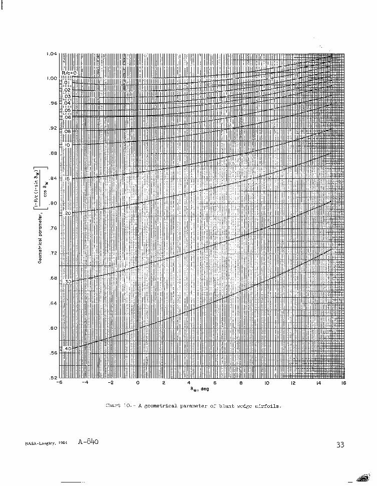
Equations (20) through (22) contain the geometrical parameter [ 1 - (R/c) (1 - s in %) ] / cos h. TO f a c i l i t a t e r a p i d e s t i m a t e s of aerody- namic c o e f f i c i e n t s of b l u n t a i r f o i l s , t h i s p a r a m e t e r i s presented in char t 10.
For evaluations of b l u n t a i r f o i l c h a r a c t e r i s t i c s ( e q s . (24), ( 2 5 ) , and (26 ) ) t h e l i f t and drag ac t ing on the l ead ing edge may be taken from the num- e r i ca l so lu t ions p re sen ted i n f i gu re 4 fo r gas spec i f i c -hea t r a t io s of 1 .2 , 1 .4 , and 1.667. These q u a n t i t i e s may a l s o be estimated with less accuracy by modified Newtonian theory using the following expressions
where a > b.
Predict ion of A i r fo i l Cna rac t e r i s t i c s
Maximum l i f t c o e f f i c i e n t .- The e f f e c t of spec i f i c -hea t r a t io on the exac t lift curves o f f l a t -p l a t e a i r fo i l s a t i n f i n i t e Mach number i s presented in f i g u r e 11 where
cz = - Y + I
2 (1 + y s in2 a - cos a d 1 - 72 s in2 a) cos a ( 3 0 )
Fla t -p la te l i f t curves exhib i t dec idedly nonl inear var ia t ions wi th angle of a t t ack and depa r t s ign i f i can t ly from impact theory as maximum l i f t c o e f f i c i e n t i s reached. The l i f t c o e f f i c i e n t a t shock detachment increases with increas- ing y , reaches a maximum a t 7 = n, and thereaf te r decreases wi th fur ther increase in 7 . It i s i n t e r e s t i n g t o n o t e t h a t t h e maximum l i f t coe f f i c i en t corresponds t o t h a t f o r shock detachment f o r Y of about 1.15, b u t f o r y < 1.15, the maximum l i f t coef f ic ien t occurs wel l below the ang le fo r shock detachment. These same e f f e c t s and t r e n d s p r e v a i l a t lower hypersonic Mach numbers, except the curves shift to the l e f t in accordance wi th the reduct ion i n shock-detachment. angle with reduction in Mach number. It should be noted the r e su l t s p re sen ted i n f i gu re 11 app ly t o any sharp-wedge a i r f o i l f o r
I 2 - a > S, i f t h e o r i g i n i s sh i f t ed a d is tance 6w t o t h e r i g h t .
The e x t e n t t o which the f l a t - p l a t e l i f t curves of f igu re 11 near detach- ment app ly t o b lun t a i r fo i l s canno t be determined by numerical solut ions. However, because of the close correla- t ion provided by hypersonic wedge theory at high angles of a t t ack ( eq . (24) and f i g . 10) it i s reason- a b l e t o e x p e c t t h a t t h e f l a t - p l a t e
a . deg solut ions predict the t rends caused Figure 11. - Effect of specific -heat ratio on by var ia t ions in both specif ic -heat
the lift characteristics of sharp flat rat i o and Mach number. airfoils at infinite Mach number.
20
I
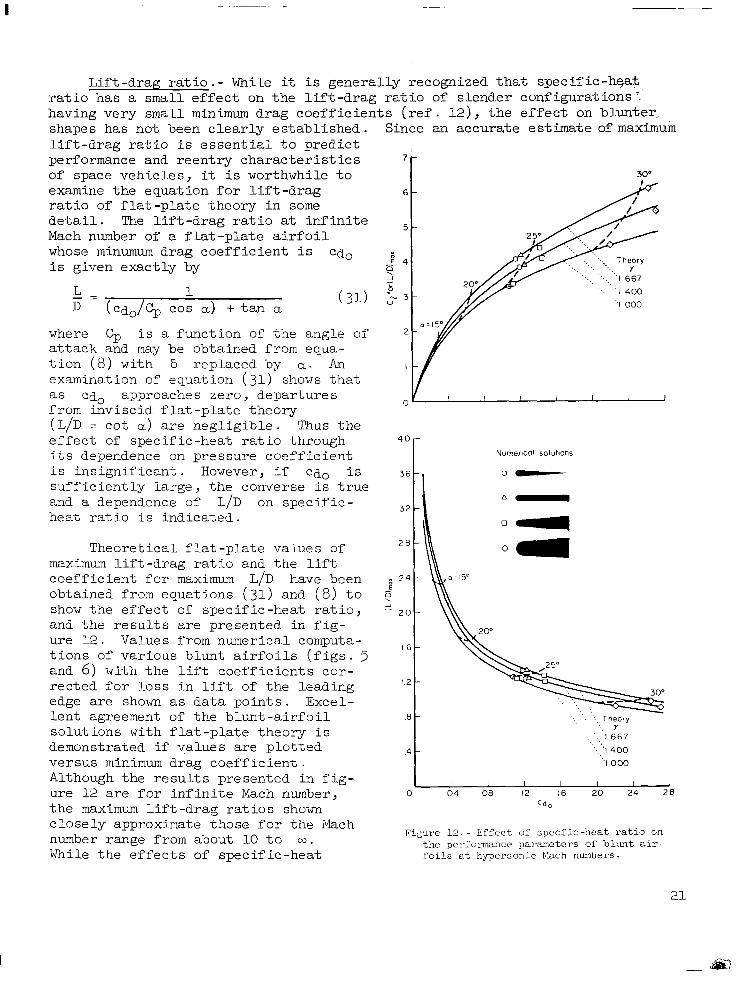
L i f t - d r a g r a t i o . - While it is generally recognized that specif ic-heat r a t i o h a s a small e f f ec t on t h e l i f t - d r a g r a t i o of s lender conf igura t ions ' having very small minimum drag coe f f i c i en t s ( r e f . 121, t h e e f f e c t on blunter shapes has not been clearly established. Since an accurate estimate of maximum lift -drag ra t io i s e s s e n t i a l t o p r e d i c t performance and r een t ry cha rac t e r i s t i c s 7 ;
of space vehicles, it i s worthwhile t o 30"
examine the equat ion for l i f t -drag 6 -
r a t i o of f l a t - p l a t e t h e o r y i n some d e t a i l . The l i f t - d r a g r a t i o a t i n f i n i t e - Mach number of a f la t - p l a t e a i r f o i l whose minumum drag coe f f i c i en t i s cdo i s given exact ly by
1 ',.. '. .. 1667
.. I 400 " L - D ( c d o / 5 c o s a) -t t a n a .I 000
where Cp i s a funct ion of the angle of 2 -
a t t a c k and may be obtained from equa- t i o n (8) w i t h 6 replaced by a . An examination of equation (31 ) shows t h a t as cdo approaches zero, departures from inviscid f l a t -p l a t e t heo ry (L/D = cot a ) are neg l ig ib l e . Thus t h e e f f e c t of spec i f ic -hea t ra t io th rough 4 0 -
i t s dependence on pressure Coeff ic ient i s in s ign i f i can t . However, i f cdo i s 36 - suff ic ient ly large, the converse i s t r u e and a dependence of L/D on spec i f i c - h e a t r a t i o i s ind ica ted .
3 2 -
Theore t i ca l f l a t -p l a t e va lues of 2 8 -
maximum l i f t - d r a g r a t i o and the l i f t c o e f f i c i e n t f o r maximum L/D have been 2 4 -
obtained from equations (31) and ( 8 ) t o 9 show the e f f e c t of spec i f i c -hea t r a t io , 2 2 0 -
and t h e r e s u l t s are p resen ted i n f i g - ure 12. Values from numerical computa- t i o n s of v a r i o u s b l u n t a i r f o i l s ( f i g s . 5 and 6) wi th the l i f t coe f f i c i en t s co r - r ec t ed fo r loss i n l i f t of the l ead ing edge are shown as da ta po in ts . Exce l - l e n t agreement of t h e b l u n t - a i r f o i l .8 -
so lu t ions w i t h f l a t -plate theory i s demonstrated i f va lues a re p lo t ted .4
'I 000 versus minimum d r a g c o e f f i c i e n t . - I 'I 400
the maximum l i f t -drag ra t ios shown = d o
ure 12 are f o r i n f i n i t e Mach number, 0 0 4 08 12 16 20 24 28 I 1 I I I I 1 Although t h e r e s u l t s p r e s e n t e d i n f i g -
1 6 -
1 2 -
. . .. . , Theory '.. Y
' ' 1667 . .
Nurnerlcal solutions
0-
closely approximate those for the Mach number range from about 10 t o 03. While t h e e f f e c t s of spec i f ic -hea t f o i l s a t hypersonic hlnch numbers.
FiLure 12 . - Effec t o f spec f i c -hea t r a t io on t h c pe1,folmance p a ~ a m c t c r s o f b l u n t a i r -
21

rat i o on maximum l i f t -drag ra t io are re la t ively unimportant for very small minimum drag coe f f i c i en t s , t he e f f ec t i s more important for large values of minimum drag coe f f i c i en t cha rac t e r i z ing b lun t a i r fo i l s . The l a r g e e f f e c t s of spec i f ic -hea t ra t io on the l i f t c o e f f i c i e n t f o r maximum l i f t - d r a g r a t i o ( f i g . 12) a re cons is ten t wi th those shown e a r l i e r f o r t h e l i f t curves of both blunt and s h a r p a i r f o i l s ( f i g . 5 ) . It i s readi ly apparent tha t Newtonian theory would s ign i f i can t ly unde res t ima te bo th t he l i f t coe f f i c i en t fo r maxi- mum l i f t -drag rat i o and the maximum l i f t -drag ra t io .
CONCLUDING REMARKS
Numerical solutions have been obtained for blunt wedges i n a pe r fec t gas . The e f f e c t s of wedge angle, nose bluntness, and spec i f i c -hea t r a t io have been determined for the Mach number range from 10 t o m. The p res su re d i s t r ibu - t i o n s have been integrated t o provide curves from which inviscid l i f t , drag, and pitching-moment c o e f f i c i e n t s of c i rcular ly blunt-wedge a i r foi ls can be evaluated.
The numer ica l so lu t ions ind ica te tha t increas ing the wedge angle of t h e b lun t a i r fo i l s s ign i f i can t ly i nc reased t he l i f t - cu rve s lope , i nc reased t he drag, and had l i t t l e e f f e c t on maximum l i f t - d r a g r a t i o . These t r ends a r e consis tent with those predicted by obl ique-shock theory for sharp a i r foi ls . Increasing the bluntness of the a i r fo i l s increased the d rag bu t a l so caused a l o s s i n l i f t which developed with increasing angle of attack. The loss i n l i f t was gene ra l ly p ropor t iona l t o t he loss i n l i f t of the leading edge. For wedge angles near Oo, the incorporat ion of b luntness t ended to l inear ize the l i f t curves a t small angles of a t t a c k . The s i g n i f i c a n t e f f e c t s of increasing gas spec i f i c -hea t ra t io were g rea t e r l i f t - cu rve s lopes and l i f t - d r a g r a t i o s .
A hypersonic wedge theory, based on expl ic i t obl ique-shock equat ions, i s shown t o provide a rap id and accura te p red ic t ion of t he aerodynamic character- i s t i c s of a i r fo i l s wi th a t tached shocks for any va lue of the specif ic-heat r a t io . me t heo ry a l so p rov ides an accu ra t e p red ic t ion of conditions a t shock detachment f o r s h a r p a i r f o i l s . For the l imi t ing case of i n f i n i t e Mach number, the theory i s exac t fo r any spec i f ic -hea t ra t io and i s i n agreement with Newtonian theo ry fo r a spec i f i c -hea t r a t io of un i ty . By account ing for the l i f t and drag of the leading edge, the theory i s shown t o be a p p l i c a b l e t o blunt airfoils for an angle-of-attack range wherein maximum l i f t - d r a g r a t i o occurs . When leading-edge bluntness i s taken into account, the theory pro- v ides an exce l len t cor re la t ion of t h e e f f e c t s of wedge angle , b luntness , and spec i f i c -hea t r a t io a t hypersonic Mach numbers. The theory i s u s e f u l f o r p red ic t ing t he maximum l i f t - d r a g r a t i o and t h e l i f t c o e f f i c i e n t a t maximum l i f t - d r a g r a t i o f o r b o t h b l u n t and sharp a i r fo i l s .
Ames Research Center National Aeronautics and Space Administrat ion
Moffet t Field, Calif. , Jan. 14, 1964
22
I
1.
2.
3.
4.
5.
6.
8.
9.
10.
11.
12.
REFERENCES %&
'i>
Linnell, Richard D.: Two-Dimensional Airfoils in Hypersonic Flows. Jour. Aero. Sci., vol. 16, no. 1, Jan. 1949, pp. 22-30.
Dorrance, William H.: Two-Dimensional Airfoils at Moderate Hy-personic Velocities. Jour. Aero. Sci., vol. 19, no. 9, Sept. 1952, pp. 593-600.
Truitt, Robert Wesley: Hypersonic Aerodynamics. Ronald Press, N. Y., 195 9
filler, Franklyn B.: Numerical Solutions for Supersonic Flow of an Ideal Gas Around Blunt Two-Dimensional Bodies. NASA TN D-791, 1961.
Van Dyke, Milton D., and Gordon, Helen D.: Supersonic Flow Past a Family of Blunt hisymmetric Bodies. NASA TR R-1, 1959.
Inouye, Mamoru, and Lor,mx, Harvard: Comparison of Experimental and Numerical Results for the Floslr of a Perfect Gas About Blunt-Nosed Bodies. NASA TN D -1426, 1962.
Ames Research Staff: Equations, Tables, and Charts for Compressible Flow. NACA Rep. 1135, 1953 .
Carafoli, Elie: On a Unitary Formula for Compression-Expansion in Supersonic -Hypersonic Flow. Revue DGMecanique Appliquge, vol. 7, no. 5 , 1962, pp. 867-876.
Hayes, Wallace D., and Probstein, Ronald F.: Hypersonic Flow Theory. Academic Fress, N. Y., 1959.
Love, Eugene S., Henderson, Arthur, Jr., and Bertram, Mitchel H.: Some Aspects of Air-Helium Simulation and Hypersonic Approximations. NASA TN D-49, 1959.

0 4 8 x / R 12 16 20 24
( b ) M, =
Chart 1.- Pressure dis t r ibut ion over the blunt-wedge surface for a spec i f ic -hea t ratio of 1.400.
.7
.6
.5
CP
.4
3
2
0
(b) M, = m
Chart 2 . - Pressure dis t r ibut ion over the bl-unt-wedge su r face f o r a s p e c i f i c - h e a t r a t i o of 1.667.
w 2 = 30° 25' 10
8
6
=I1
4
2
0 30°
200
I5O
IO0
50
00
W" 50 IO0 150 io0 250 300
0 4 8 12 16 20 24 x /R
( b ) Moo =,
Chart 3 . - Contribution of the blunt leading edge and wedge sur faces t o l i f t c o e f f i c i e n t f o r a s p e c i f i c - h e a t r a t i o o f 1.400.
26
wL = 30° 10
8
2
0 wu=Oo 5 O 20° 30°
( a ) M, - 10
10
200
2
w.. = 5' 10' 15' 20' 25' 30'
0
-20
-40
C k
-60
-80
-100
( a ) M, = 10
w,, 5' 10' 15' 20' 25' 30' 0
-20
-40
C;,
-60
- 80
- I nn ." 0 4 8 12 16 20 24
x/R
(b) M, = w
Chart 5 . - Contr ibut ion of the blunt leading edge and wedge surfaces to pitching-moment c o e f f i c i e n t ; 7 = 1.400.
28
IO
8
6
c;
4
2
a wu= 5O IOo 15O 20° 25O 30'
( a ) M, = 10
IO
8
6
ci
4
2
0 wu= 5O IOo 15O 20° 25O 30°
0 4 8 12 16 20 24
x/R
( b ) M, = m
Chart 6.- Contribution of t he b lun t l ead ing edge and wedge s u r f a c e s t o l i f t c o e f f i c i e n t f o r a s p e c i f i c - h e a t r a t i o of 1.667.
IC
2
0 I
w u = 20' 30°
( a ) M, = 10
w u = 2 0 0 30° 0 4 8 12 16 20 24
x/R
(b ) M, = m
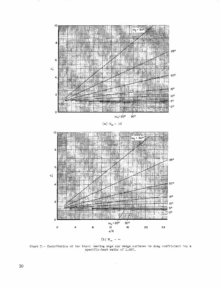
C h a r t 7 . - Contribution of t he b lun t l ead ing edge and wedge su r faces t o d rag coe f f i c i en t for a s p e c i f i c - h e a t r a t i o of 1.667.
30
I
1
0
- 20
-40
-60
-80
100
( a ) Mm = 10
WII '5" IOo 15" 20" 25" 30°
0 4 8 12 16 20 24
x/R
( b ) M, =
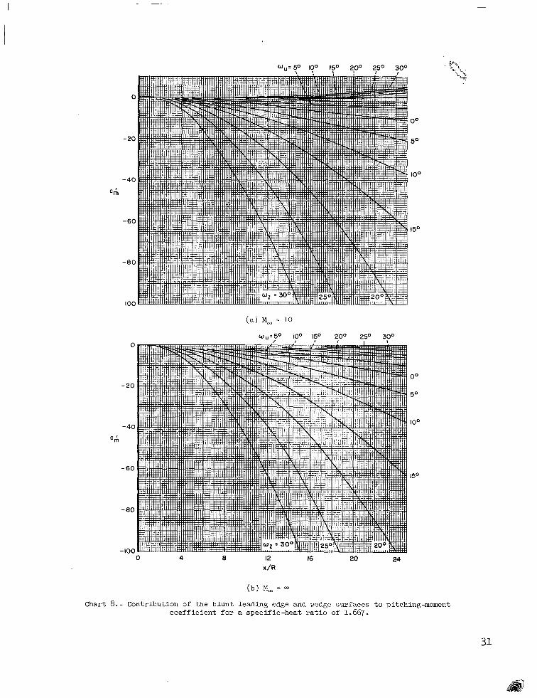
Chart 8.- Contribution of the blunt leading edge and wedge surfaces to pitching-moment c o e f f i c i e n t f o r a s p e c i f i c - h e a t r a t i o of 1.667.
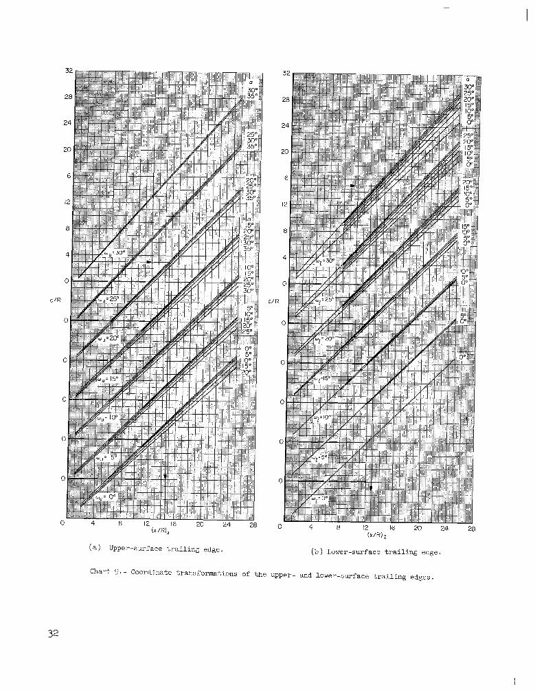
0 4 8 12 16 20 24 28 (x /R) z
(b) Lower-surface trailing edge.
I .04
I .OQ
.96
.92
.88
E .76
0 a
.6 8
.64
.6 0
.56
.5 2 -6 -4 -2 0 2 4 6 8 10 12 14 16
a,, deg
Chart 10. - A geometrical parameter of blunt wedge airfoils
NASA-Langley, I964 A-840 33