Embed Size (px)
Citation preview

THEODOLITE: INTRODUCTION
INTRODUCTION
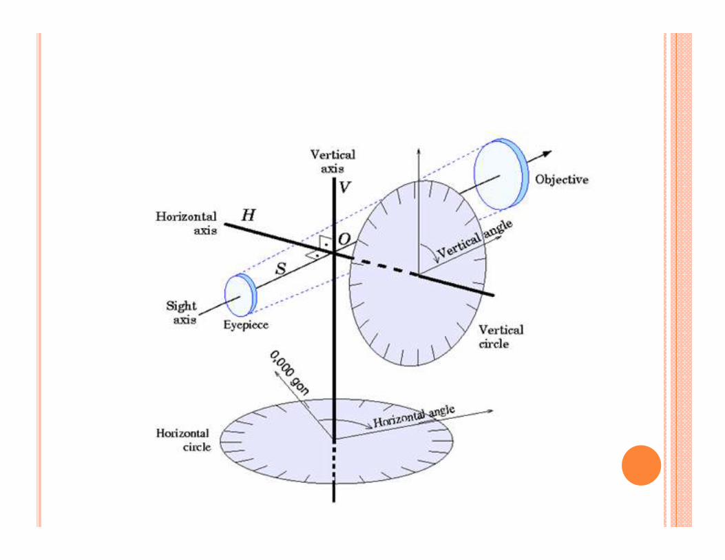
� Theodolite is used to measure the horizontal and vertical angles.
� Theodolite is more precise than magnetic compass.
� Magnetic compass measures the angle up to as accuracy of 30’. However a vernier theodolite
measures the angles up to and accuracy of 10’’, 20”.
� There are variety of theodolite vernier, optic,
electronic etc.
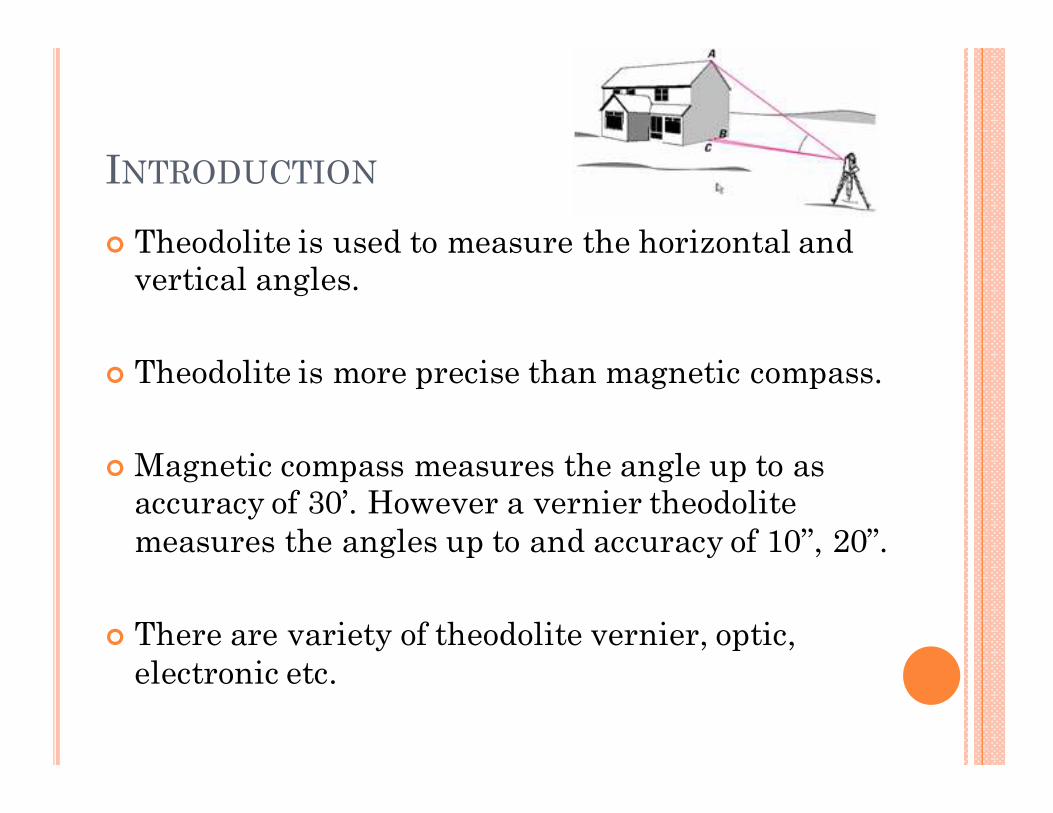
TYPE OF THEODOLITE
VERNIER THEODOLITE
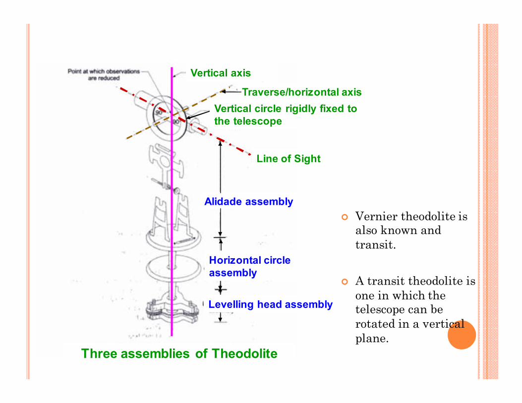
� Vernier theodolite is also known and
transit.
� A transit theodolite is
one in which the telescope can be
rotated in a vertical
plane.
Alidade assembly
Horizontal circle
assembly
Levelling head assembly
Line of Sight
Traverse/horizontal axis
Vertical circle rigidly fixed to
the telescope
Vertical axis
Three assemblies of Theodolite
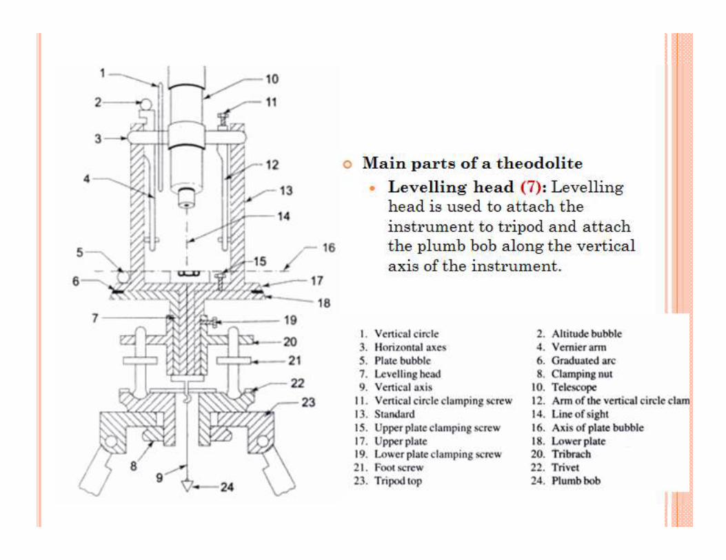
� Main parts of a theodolite
� Levelling head (7): Levelling head is used to attach the
instrument to tripod and attach the plumb bob along the vertical
axis of the instrument.

MAIN PARTS-2
� Lower plate/circle plate (18): an annular horizontal plate with the graduations provided all around, from 0 to 360°, in a clockwise direction. The graduations are in degree divided in to 3 parts so that each division equals to 20 min.
� Horizontal angles are measured with this plate.
� The size of the theodolite is defined by the diameter of horizontal circle.
� Upper plate (17): Horizontal plate of smaller diameter provided with two verniers. on diametrically opposite parts of its circumference. These verniers are designated as A and B. They are used to read fractions of the horizontal circle plate graduations. The verniers are graduated in 20 min and each minute is divided in 3 to 5 parts making least count 20” or 10”.

MAIN PARTS-3
� Clamps and tangent screws (15, 19):
� There are two clamps and associated
tangent screws with the plate. These screws
facilitate the motion of the instruments in
horizontal plane.
� Lower clamp screw locks or releases the
lower plate. When this screw is unlocked
both upper and lower plates move together.
The associated lower tangent screw allows
small motion of the plate in locked position.
� The upper clamp screw locks or releases the
upper vernier plate. When this clamp is
released the lower plate does not move but
the upper vernier plate moves with the
instrument. This causes the change in the
reading. The upper tangent screw allows
the fine adjustment.
MAIN PARTS-4
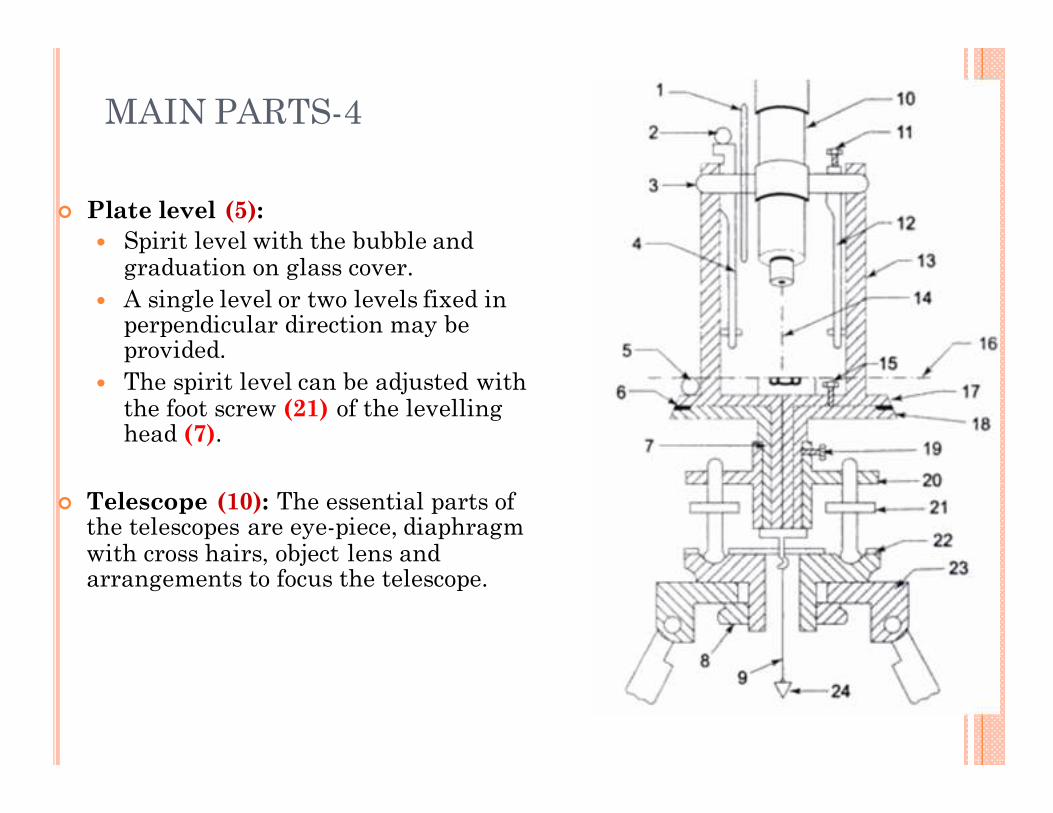
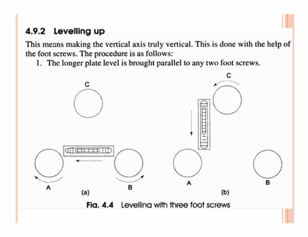
� Plate level (5):
� Spirit level with the bubble and graduation on glass cover.
� A single level or two levels fixed in perpendicular direction may be provided.
� The spirit level can be adjusted with the foot screw (21) of the levelling head (7).
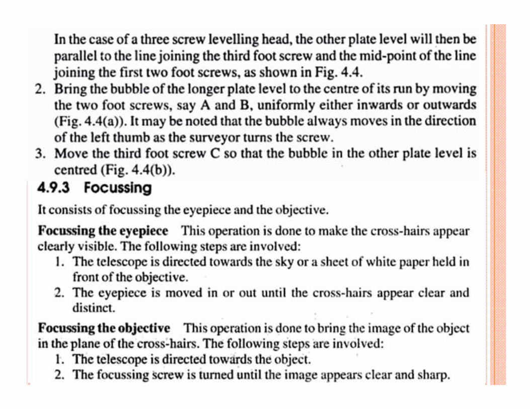
� Telescope (10): The essential parts of the telescopes are eye-piece, diaphragm with cross hairs, object lens and arrangements to focus the telescope.
MAIN PARTS-5
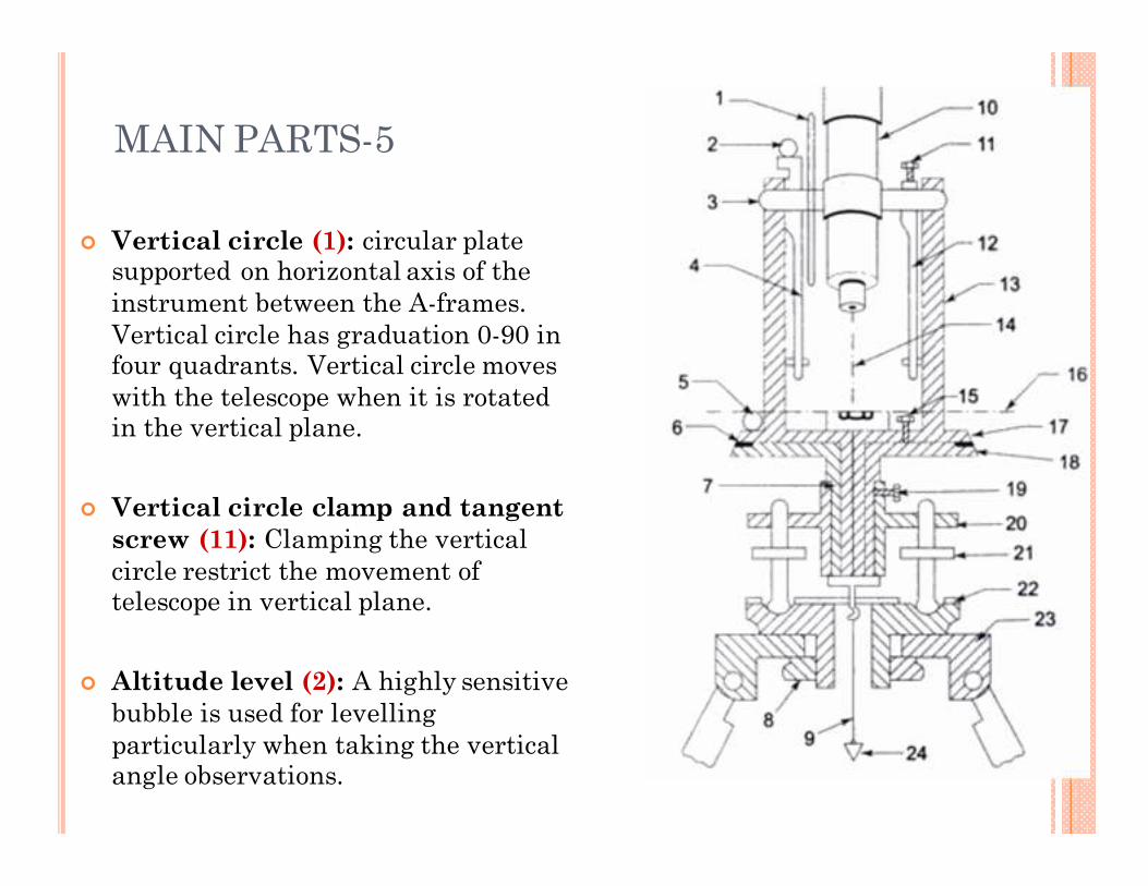
� Vertical circle (1): circular plate supported on horizontal axis of the
instrument between the A-frames.
Vertical circle has graduation 0-90 in four quadrants. Vertical circle moves
with the telescope when it is rotated in the vertical plane.
� Vertical circle clamp and tangent
screw (11): Clamping the vertical
circle restrict the movement of telescope in vertical plane.
� Altitude level (2): A highly sensitive
bubble is used for levelling
particularly when taking the vertical angle observations.
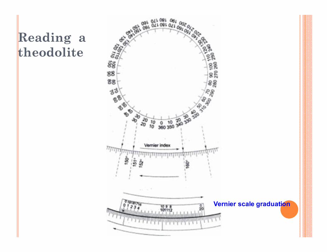
Reading a
theodolite
Vernier scale graduation
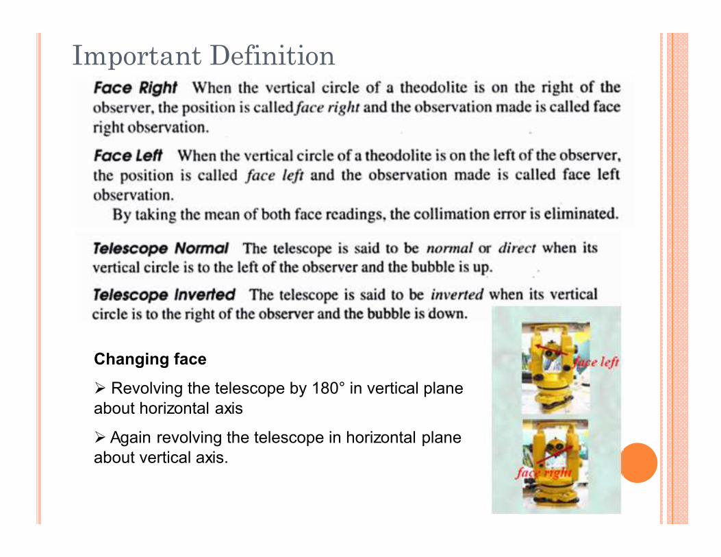
Important Definition
Changing face
� Revolving the telescope by 180° in vertical plane
about horizontal axis
� Again revolving the telescope in horizontal plane
about vertical axis.
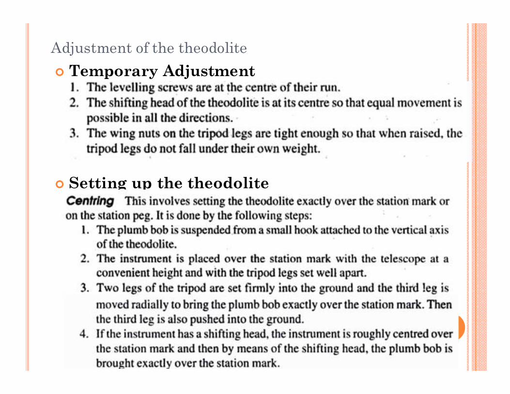
Adjustment of the theodolite
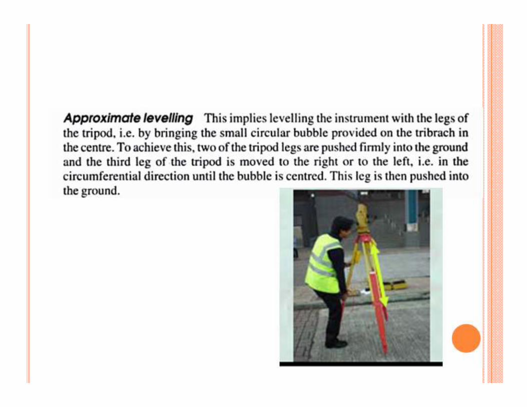
� Temporary Adjustment
� Setting up the theodolite

Measurement of horizontal angle
� Measurement of Angle ABC
� The instrument is set over B.
� The lower clamp is kept fixed and upper clamp is loosened.
� Turn the telescope clockwise set vernier A to 0° and
vernier B to approximately 180°.
� Upper clamp is tightened and using the upper tangent screw the vernier A and B are exactly set to 0° and
180°.
� Upper clamp is tightly fixed, lower one is loosened and telescope is directed towards A and bisect the ranging
rod at A.
� Tightened the lower clamp and turn the lower tangent screw to perfectly bisect ranging rod at A.
� Loose the upper clamp and turn the telescope clockwise
to bisect the ranging rod at C tightened the upper clamp
and do the fine adjustment with upper tangent screw.
� The reading on vernier A and B are noted. Vernier A
gives the angle directly and vernier B gives the reading
by subtracting the initial reading (180°) from final reading
� Read these two method
� Repetition method
� Reiteration method
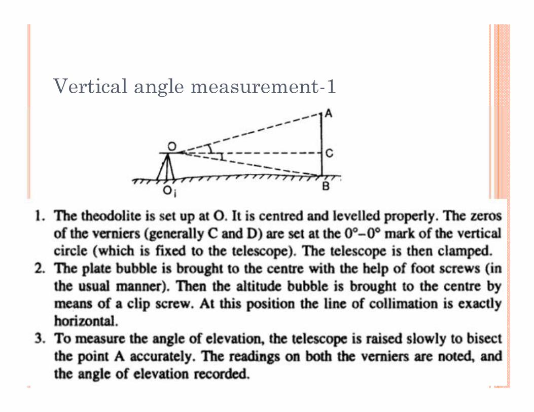
Vertical angle measurement-1
Vertical angle measurement-2
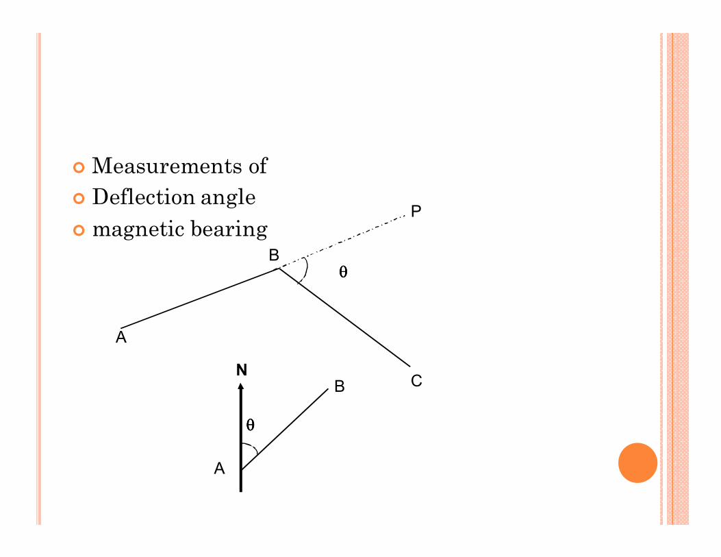
� Measurements of
� Deflection angle
� magnetic bearing
A
B
C
P
A
B N
θθθθ
θθθθ
� Read assignment (N. N. Basak, S. K. Duggal)
� Ranging and extending a line
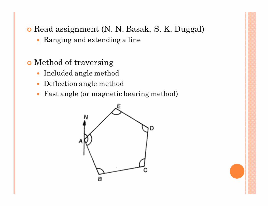
� Method of traversing
� Included angle method
� Deflection angle method
� Fast angle (or magnetic bearing method)
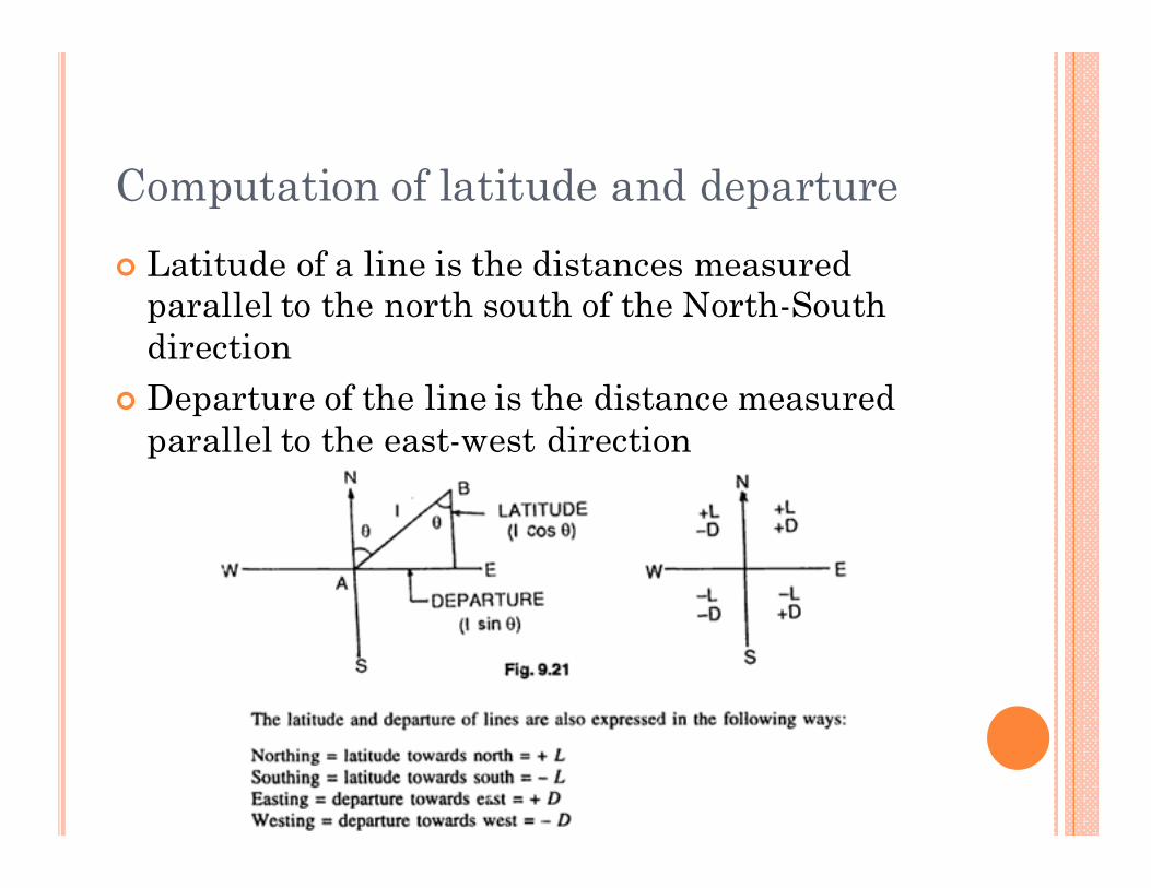
Computation of latitude and departure
� Latitude of a line is the distances measured parallel to the north south of the North-South
direction
� Departure of the line is the distance measured
parallel to the east-west direction
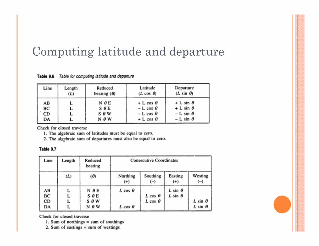
Computing latitude and departure
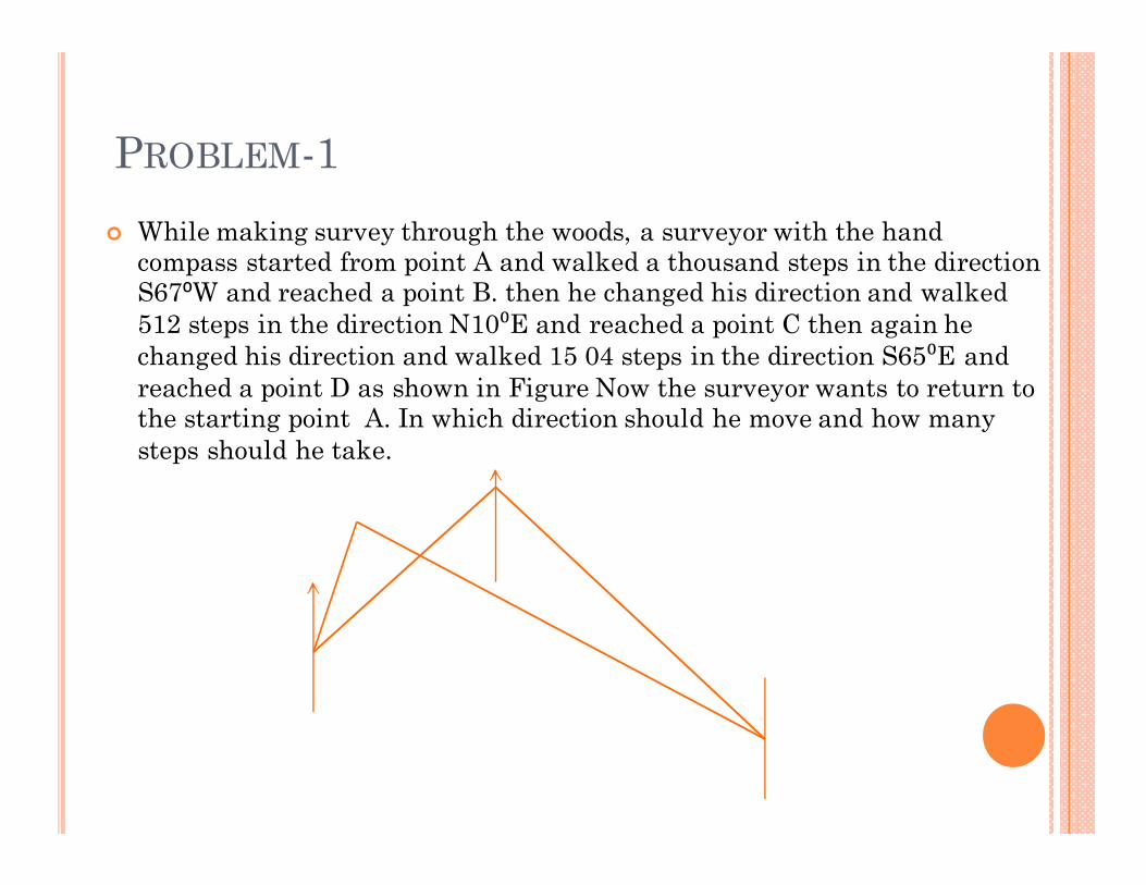
PROBLEM-1
� While making survey through the woods, a surveyor with the hand compass started from point A and walked a thousand steps in the direction S67⁰W and reached a point B. then he changed his direction and walked
512 steps in the direction N10⁰E and reached a point C then again he
changed his direction and walked 15 04 steps in the direction S65⁰E and
reached a point D as shown in Figure Now the surveyor wants to return to the starting point A. In which direction should he move and how many
steps should he take.
Sources of errors in theodolite
� Instrumental errors
� Non adjustment of plate bubble
� Line of collimation not being perpendicular to
horizontal axis
� Horizontal axis not being perpendicular to vertical
axis
� Line of collimation not being parallel to axis of
telescope
� Eccentricity of inner and outer axes
� Graduation not being uniform
� Verniers being eccentric
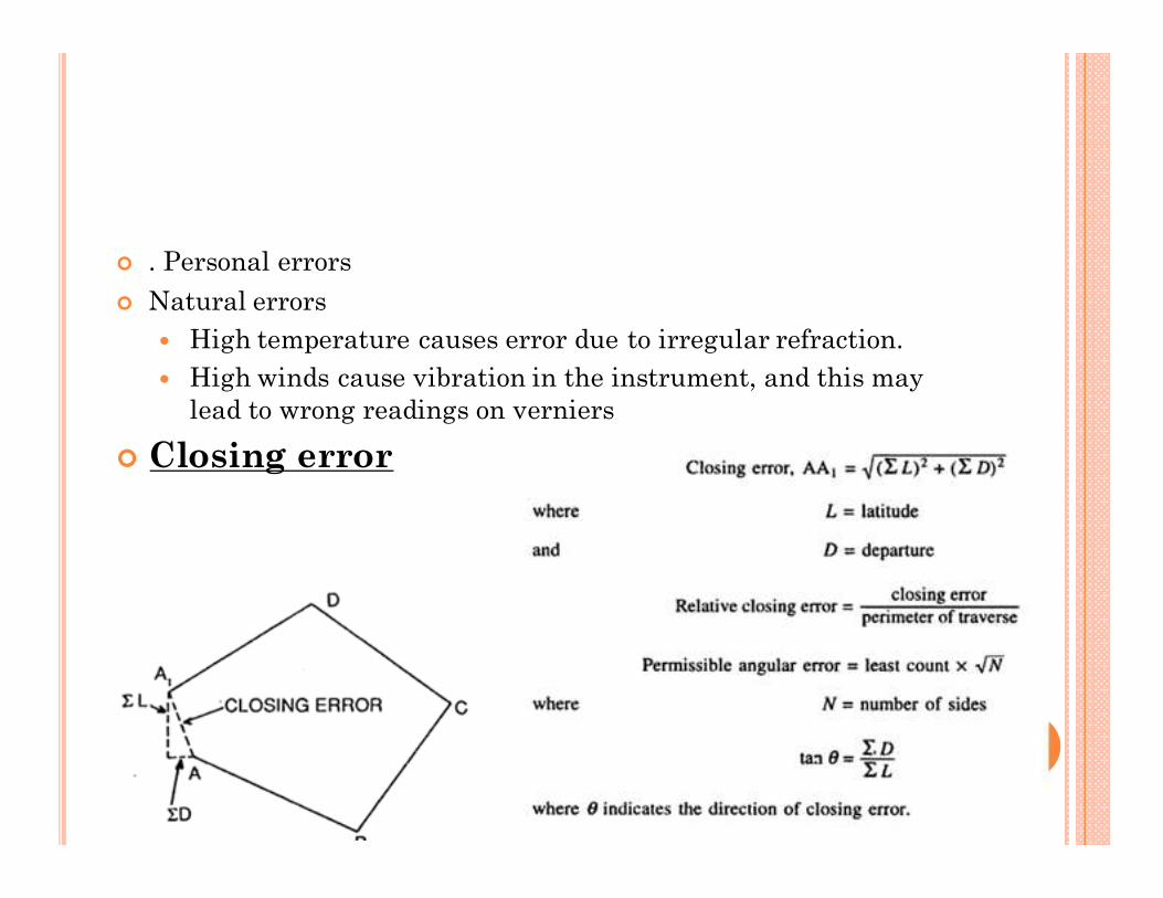
� . Personal errors
� Natural errors
� High temperature causes error due to irregular refraction.
� High winds cause vibration in the instrument, and this may
lead to wrong readings on verniers
� Closing error
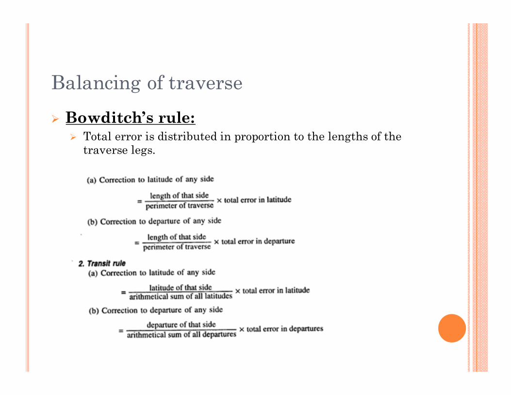
Balancing of traverse
� Bowditch’s rule: � Total error is distributed in proportion to the lengths of the
traverse legs.
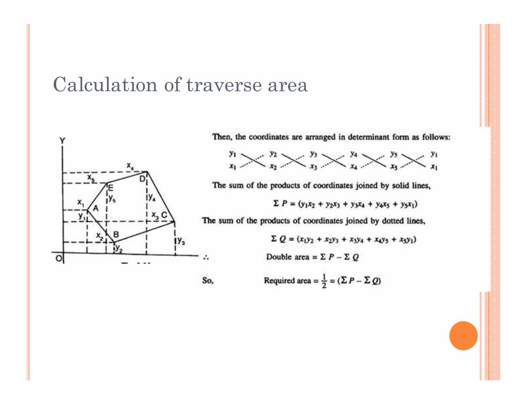
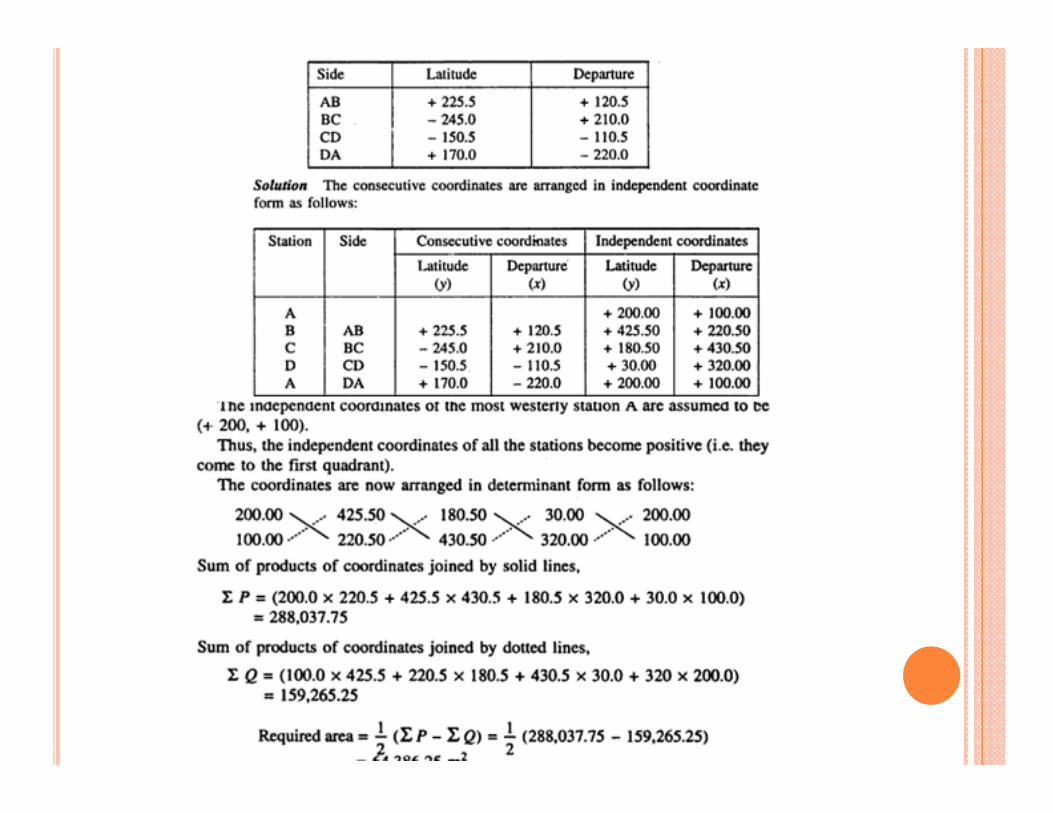
Calculation of traverse area
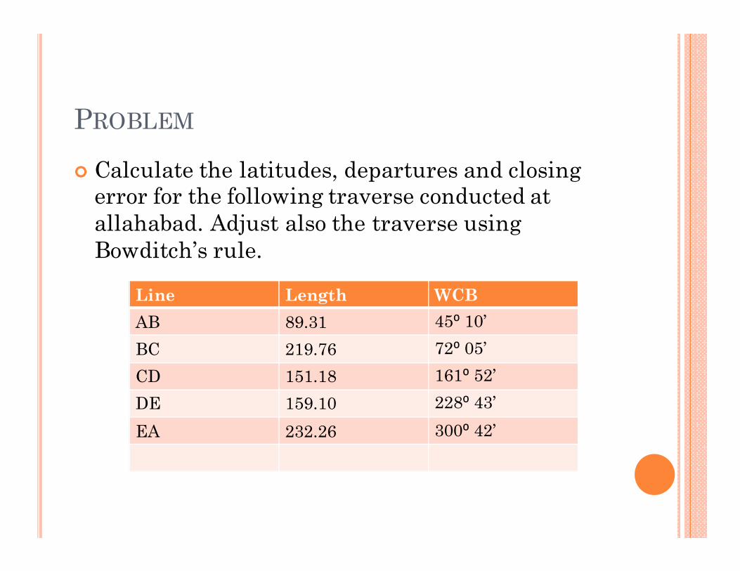
PROBLEM
� Calculate the latitudes, departures and closing error for the following traverse conducted at
allahabad. Adjust also the traverse using
Bowditch’s rule.
Line Length WCB
AB 89.31 45⁰ 10’
BC 219.76 72⁰ 05’
CD 151.18 161⁰ 52’
DE 159.10 228⁰ 43’
EA 232.26 300⁰ 42’