Embed Size (px)
Citation preview

Thematic Unit of Excellence on Computational Materials Science(TUE-CMS)
Solid State and Structural Chemistry UnitIndian Institute of Science
Bangalore 560012
Open Tender Request for Proposal for Datacenter
Reference No. SSCU/TUE/DC/2015-186 dated 26th June, 2015
1

Table of Contents1.0 Solution Overview................................................................................................................4
1.1 Physical Components Design.....................................................................................41.2 Existing floor and DC space.......................................................................................51.3 Detailed Product-wise scope.......................................................................................5
1.3.1 Raised floor....................................................................................................51.3.2 Sub structure – pedestal assembly..................................................................51.3.3 Stringers..........................................................................................................61.3.4 Other Non structural Parameters....................................................................61.3.5 Fire Rated Gypsum Partition across the room................................................7
1.4 Rack Specifications.....................................................................................................71.4.1 Technical specifications:.................................................................................71.4.2 PDU - Power Distribution Unit for Rack (N+1)............................................81.4.3 Closed Loop Rack based cooling system.......................................................81.4.4 High Performance Liquid Cooling Package – Closed Loop Cooling............8
1.5 Air-Conditioning.........................................................................................................92.0 Monitoring..........................................................................................................................113.0 Rear Auto door Opening for Closed Loop Cooling System...............................................12
3.1 Precision Air conditioning........................................................................................123.2 Air Cooled Chillers: (N+1 Redundancy)..................................................................123.3 Technical specifications:...........................................................................................13
4.0 LOW SIDE WORKS: PUMPS & PIPING........................................................................155.0 Security Systems................................................................................................................16
5.1 Fire Detection and alarm System:.............................................................................175.2 Manual pull station:..................................................................................................175.3 Very Early Smoke Detection and Alarm [VESDA] SYSTEM.................................17
5.3.1 Introduction:.................................................................................................175.3.2 Design:..........................................................................................................175.3.3 Principle of Operation:.................................................................................18
5.4 Rodent Repellent System:.........................................................................................185.5 Water Leak Detection System:..................................................................................19
6.0 BUILDING MANAGEMENT SYSTEM (BMS)..............................................................196.1 SCOPE OF WORK...................................................................................................196.2 Electrical System......................................................................................................19
7.0 Services Level Agreement (SLA) & Warranty...................................................................208.0 General terms and conditions:............................................................................................219.0 USER ACCEPTANCE TEST CHECK LIST.....................................................................2210. CHECK-LIST.....................................................................................................................2211. POWER CONSUMPTION CHECK LIST:.......................................................................2212.0 Submission of Proposal....................................................................................................2313.0 PRICE BID TABLE.........................................................................................................2314.0 Likely Time-line...............................................................................................................2415.0 Bill of Quantities..............................................................................................................25
15.1 - Air cooled Chiller.................................................................................................2515.2 – Civil Works..........................................................................................................2815.3 – Cooling Racks......................................................................................................2815.4 – Security products.................................................................................................28
15.4.1 Fire Alarm...................................................................................................2815.4.2 VESDA.......................................................................................................2915.4.3 Water leak detection system.......................................................................29
2

15.4.4 Rodent repellent system.............................................................................2915.4.5 BMS system................................................................................................30
15.5 – PAC Cooling unit.................................................................................................3015.6 – UPS for Pump......................................................................................................31
Bidders may obtain the Request For Proposal (RFP) which includes TechnicalSpecifications and Bill of Quantities from Ms. Bavitha, Room 209, SSCU, INDIANINSTITUTE OF SCIENCE, C V Raman Ave, Bengaluru, Karnataka 560012.Bidders can also download RFP Documents on this Institute’s websitehttp://www.iisc.ernet.in/tender/index.php however they are required to pay tenderfee in the manner as prescribed below along with Bid document. Documents mustbe in two cover format with technical part and commercial part in two separatesealed covers. They must be superscribed as ‘Technical Bid' and ‘Commercial Bid’.The bids should be accompanied by a nonrefundable DD for Rs. 5,000 / - (Rs. FiveThousand only) drawn in favour of “Registrar, INDIAN INSTITUTE OFSCIENCE” payable at Bangalore.
3

1.0 Solution Overview
IISc SSCU is in need of Tier 3 Data Center (DC) for its HPC server Project. This bid is tobuild cooling solution for High Performance Computers (HPC) along with racks, electricalcabling & Security products for DC. The room dedicated to the data center has an area of 588sq ft. The floor to ceiling height is only 9 ft and 6 inches. The solution could use all or part ofthis space. The scope is for supply, installation and maintenance for a period of 5 years.
The DC area should support presently 7 nos of 800 mm width server rack of 42U. Only 4racks with a total capacity of 110kW is expected now but provision for possible addition infuture of 3 more racks should be made. Chilled water based cooling solution should beprovided to achieve PUE of 1.5 or lower. UPS power supply from Existing UPS of 2 x 160kVA will be provided close to the DC. The power distribution from existing UPS outputpanel’s to racks including DB installation in Server room and individual socket for racks is insupplier scope. Dual power source per rack shall be provided.
Two UPS each of capacity 160 kVA and one diesel generator (DG) have already beeninstalled and supply from these to the data center will be made available.
Closed loop cooling solution ( CLC ) to support 110 kW heat load across 4 racks shall beprovided & should be expandable up to 7 racks without any dependency. The closed loopcooling solution should have N+1 redundancy (both for indoor unit and chiller and allpumps) and should be adaptable in case the heat load increases up to a rack density of 35kW/rack with just addition of cooling unit as in modular datacenters. Dual chiller plant equalto or not less than 40 Tr actual capacity on ambient temperature 37°C shall be provided on N+ 1 configuration. Open space behind the server room shall be used for installing chillerplant.
1.1 Physical Components Design
IISc is in need of Turnkey Implementation of the Data Center including ProgramManagement Services for Data Center Set Up. The bidder/solution provider shall submitDetailed Engineering Drawings of various components of Data Center and revise the same asrequired till the drawings/design is finally approved by IISc and that also includes alldrawings like air conditioning, electrical system, Fire alarm systems, data cabling etc.
Preparing detailed specifications and supply Installation and Commissioning of the followingcritical components for Data Center is required:
Civil – Partition & Raised floor
Electrical System for Data Center cabling from UPS to DC and all cabling within DC
CLC Cooling Systems
Air cooled chiller and piping
Power Distribution and cable management From UPS to Racks
Fire alarm, suppression and VESDA system
Water Leak Detection System
Pest Control (Rodent Repellent System)
4

1.2 Existing floor and DC space
A smaller portion from given space of 12.3Mtr x 4.2Mtr may be used for DC. One fire rateddoor out of two provided to be used for server room after building partition wall across thespace. Raised floor of 1500 USF at the height of 300 to 400 mm. Metal steps to be providedfrom fire rated door for entry.
1.3 Detailed Product-wise scope
1.3.1 Raised floor A total of 588 sq ft raised floor with below spec to be provided.
Unitile® USF 1500 Access Floor panel of size 600x600 mm shall be all steel weldedconstruction, with an enclosed bottom pan of 49 hemispherical and 36 reverse cones andtop plain sheet which are fuse welded at 129 locations to form a panel of an overall thicknessof 35mm. The panel after cleaning, degreasing, phosphating by 11 tank process is coated with40-60 micron epoxy coat and is heated to achieve maximum adhesion to the panel surfaceand corrosion resistance. The inner empty core of the panel is injected with a light weight fireretardant, non combustible cementitious compound at high pressure to fill in all the crevicesof the panel and ensures support of not less than 90% of the top surface area of the panel.
The panel is then laminated with 1.5/2.00 mm thick fire retardant floor grade AntistaticLaminate / ESD Laminate - PVC / Conductive / Dissipative PVC on a semi -automatedlamination line to ensure maximum bonding to the steel surface. The edges of the laminatedare protected with conductive PVC edge trim 5mm wide on all sides. This edge trim ismechanically locked and sealed in place to avoid detachment.
1.3.2 Sub structure – pedestal assemblySub structure installed to support the panel shall be suitable to achieve a minimum finishedfloor height of 300 mm to a maximum of 400 mm from the existing floor level. Pedestaldesign shall confirm speedy assembly and removal for relocation and maintenance. Theassembly shall provide easy adjustment of leveling and accurately align panels for amaximum ± 25 mm in the vertical direction. Pedestals shall support an axial load withoutpermanent deflection and an ultimate load as laid out in System Performance requirement.
The Pedestal head assembly shall consist of a 75 x 75 x 3.50 mm embossed headmechanically riveted to a 100 mm long ¾” dia rolled formed stud and 2 check nuts for leveladjustment and arresting vertical movement. The pedestal head shall consist of an anti-vibrational PVC cap for Panel location. The Pedestal Base assembly shall consist of 22.23 mm OD pipe mechanically locked on apress for perpendicularity and then welded to a base plate of 100 x 100 x 2 mm thick withstiffening folds.
The sub structure assembly shall be suitably anchored to the floor with suitable adhesive orfastener as recommended by the consultant / manufacturer. All steel components shall be zincelectro plated.
5

1.3.3 Stringers
The stringer is hot dipped galvanized steel cold rolled construction specially designed withribs embossed on 3 sides for strength, lateral stability, and for enhanced rolling loadsperformance and to support the panels on all four sides for alignment. The stringer to have acounter sunk holes at both ends to accommodate bolting of M6 machine screws to thepedestal head assembly. The stringers shall be 21 x 32 x 0.8 x 570 mm length.
Concentrated Loads :
675 Kgs (1500 lbf ) with a top-surface deflection under load and a permanent set not toexceed , respectively, 2.54 & 0.25 mm ( 0.10 & 0.010 inch ) according to CISCA A/F, SectionI ‘’ Concentrated Loads’’
Ultimate Concentrated Load:
1690 Kgs (3750 lbf ) without failing according to CISCA A/F, Section II ‘’ Ultimate Loading’’
1.3.4 Other Non structural Parameters
• Fire Rating : The Panels shall confirm to Class O & Class 1 Fire Ratings tested as per BS 476 Part 6 (FirePropagation) & 7 (Surface spread of flame) as also ASTM E84 1998 (Flammability) andASTM E136 (Combustibility)
• Electrical Resistivity :
As per ASTM F150/ NFPA 99 / ANSI S7.1/ CEI 61340 but modified for surface to ground toplace one electrode on the floor surface and to attach the other electrode on the pedestal.Resistance to be tested at 100 / 500 volts:
1. Conductive range : 2.5x10⁴ – 1x 10⁶ Ohms (surface to ground) 2. Static dissipative range : 1x10⁶- 1x10⁹ Ohms (surface to ground) 3. Anti static range : 1x10⁹ – 2x10¹⁰ Ohms (surface to surface )
• Fabrication Tolerance
A. Floor panel flatness : ± 0.75 mm in any direction B. Floor panel width or length from specified size : ± 0.50 mm C. Floor panel squareness : ± 0.38 mm
• Installation Tolerance
A. Overall level before application of any load : ± 1.5 mm over any 5.00 Sqmt ± 6 mm over any size of basic space
B. Panel level : + 0.75 mm before the application of any load C. Panel Interchangeability installation and removal : shall be interchangeable (except forfield cut panels) and replaceable in any of the four directions at 90º increments
6

Floor grills of 600 x 600 mm floor grills 4numbers to be provided.
1.3.5 Fire Rated Gypsum Partition across the room
Twin layer of 6 mm Fire resistant gypsum board to be used on both the sides of the wallstretcher.
The height shall be 9.5 ft from floor to ceiling (approximately). All the windows inside theserver room to be closed with gypsum board to avoid heat conductivity from outside. Puttyworks to be carried out on the existing wall and gypsum board and three coat of water basedpainting to be carried out.
1.4 Rack Specifications
Server Rack 800 mm Width x 42U Height x 1200mm Depth.: 04 Nos.
These racks will be used to mount and house all server/network/storage devices in the data center.
The rack has to be designed to meet the safety requirements of the modern data centre. Boththe front and rear door should have a handle with locking options. The rack should besuitable for baying to a high performance cooling rack. Cable entry should be entered via theroof plate and via the gland plate without affecting the climatic conditions inside the rack.
1.4.1 Technical specifications:
Server Equipment Cabinets - 42U - 800 mm Width x 1200 mm Depth equipment cabinetsshould have adjustable 19 inch front and rear vertical mounting extrusions which are EIA-310D and IEC 60297 compliant and allow up to 1190 mm of depth for equipment mounting(in rack the usable depth is 800 mm due to hot and cold zone within the IP54 sealed block).Balanced load rating of 1500 kg. Cabinet should be manufactured from materials andprocesses that are compliant with the most current TÜV/ISO environmental managementstandards. The front and rear 19 inch equipment mounting rails and other internal supportingmetals are to be of un-painted galvanized steel. Cabinet shall come complete with groundingkit, cage nuts and the following features and installed accessories:
Front door – lockable glass door with key, Opening angle 180°
Rear door – with automatic opening capability, Opening angle 180°
Air separation frame for air-flow optimization and elimination of bypass air-flow, consisting of mechanically joint sheets steel panels and equipped with thesealing rim.
Balanced Load rating 1500 kg
Bottom is flat and enables direct installation of the rack on the floor
Adjustable leveling feet (4 pcs.)
IP54 protection rating when installed (joined to neighboring cooling unit forclosed loop)
Central grounding point
Rack based fire suppression – fitted inside rack with max size of 4U on eachrack.
7

1.4.2 Three Phase PDU - Power Distribution Unit for Rack (N+1)
Each Server and Network Rack should be fitted with 2 nos. rack mounted power Distributionunit with 24 nos. IEC C13 and 6nos. IEC C19 - for Server (high density racks); PDU shallhave the capability to monitor the power consumption of the rack on which it is mounted.
Protocols: SNMP, Telnet, http etc.
1.4.3 Closed Loop Rack based cooling system
The Data center should be equipped with Liquid Cooling System; it is an air/water heatexchanger to remove high levels of waste heat from server enclosures and to provideuniform, effective, affordable cooling for Servers and similar IT equipment (switches etc)installed in server enclosures. Each liquid cooling system should be a closed unit consistingof a cooling system and cool either one or two server enclosures.
1.4.4 High Performance Liquid Cooling Package – Closed Loop Cooling.
CLC Rack CW should offer enclosure-based cooling separate from the room air and is thusalso able to reduce the noise level. The unit should be capable of providing cooling for eitherone or two server racks. The hot server air should be drawn off to the rear of the server rack.After cooling, it should be expelled at the rear of the rack and is thus made available to the ITequipment once more.
Unit should be connected to the piping system of chilled water or anti-freeze mixture. It issuitable for the free-cooling systems because allows warmer water usage. The surfacetemperature of the heat exchanger is controlled by valve, which fluently modifies the coolingcapacity in accordance to the actual demand. Variable speed fans help to keep always thecorrect airflow for all IT equipment in data center. EC motor technology used in the fansmarkedly reduces the annual power consumption.
Both top and bottom connection of the unit is available.
The air-conditioning unit’s design has to be fully compatible to bystanders IT racks from theperspective of dimensions, material, color, and mechanical coupling elements. The unit in therow of the cabinets has to enable an installation of cable management, roof elements, aisledoors etc. There must be redundancy in the indoor cooling units (PAC as well as CLC).
1.5 Air-Conditioning
Air-conditioning unit includes:
- Highly efficient water heat exchanger made of copper pipes and aluminum finswith a special surface. The oblique position of HX enlarges the surface, andoptimizes the heat transfer.
- Three stacked air filters of filtration class G4 in combustible finish for ecologicaldisposal. The frame is ready for easy maintenance and filter replacement.
8
- Five or more hot-swap radial fans with EC motors significantly reducing thepower consumption with fluent speed change and operation feedback to thecontrol system.
- Controller with software for independent control of all components, running alsoin case of interruption of communication between units or central display.
- Minimum Four temperature sensors located in the front and rear side monitoringthe air temperature in the upper and lower part of the space. Sensors could becalibrated from controller. Controller enables to change the logic between averageand maximal values, and arranges substitutability in case of failure.
- Two humidity sensors located at the bottom of front and rear part of the unit forprecise monitoring of the room conditions.
- Air-conditioning unit, with “D” in the type code, includes color touch screen inthe front door. 4.3” large display is equipped with special software for monitoringand control of up to 10 units. It enables communication through TCP/IP protocol,remote control via Ethernet and implemented webserver, and easy SW upgradingand data downloading via USB disk or SD card. Another function implementationis possible on special request.
Functions:
- The basic task is to cool down the air from the hot zone of datacenter anddistribute it to the cold zone in front of the IT equipment. The unit is designed tokeep the constant temperature in both zones thanks to the water valve adjustmentand variable fan speed.
- If the humidity in the hot zone is within the limits set by an administrator, then theunit’s internal logic tries to avoid any condensation of the air moisture, maximizethe cooling efficiency, and minimize influence on the humidity climate of theroom.
- Avoid condensation completely and maximize cooling efficiency.- If the measured air humidity is above the set point, then the unit is automatically
switched to the dehumidification mode, and actively supports the surfacecondensation to decrease the humidity in the room. The resulted condensate isdischarged to the drainage.
- The unit can be equipped by integrated steam humidifier which increases the roomhumidity to the set point.
- PAC should control humidity.- Units could be connected to bigger groups under a superior control with advanced
control logic (sequencing, team working, overload start, etc.)
Technical specifications:
Adaptable cooling output : Equal to or greater than 30kW.
Installed fans: 4 Minimum
Air throughput: Equal to or greater than 3800 m³/h
Cooling output : Equal to or greater than 30 kW
9
Air intake temperature: 35°C
Water inlet temperature: as required
Medium: Water
Coolant throughput: approx. 60 l/min as required
Pressure loss: approx. 1 bar
Voltage: 208/230 V, 1~, 50 Hz, 400 V, 3~, N, 50 Hz
Colour: NA
Usable installation height: free (standard: 42 U)
Dimensions: WxHxD: 300 or 600 x 2000 x 1200 mm
Touch screen display, Connection hose, bottom/top:
2.0 Monitoring 8 intelligent ports (output/input, 0-5V) with auto sense on main device with 4
expansion ports Expandable solutions through expanders connected in daisy-chain with patch
cables Intelligent port presented by RJ-45 for connection and extension by patch cable Options to upload picture and with a function grab & drop able to place sensors
icon in Multi language with a possibility to create own language version inside of device 80 virtual sensors for connecting and reading a values from SNMP devices,
Modbus devices and Ping Email, SNMP trap, Modbus control, skype call & sms, speech Support a sending keep alive emails in configurable interval SNMP v1, v2 & v3 Support DHCP and NTP Fully embedded TCP/IP and web-server with Linux OS A standalone product without any external hardware and software dependencies. Configurable User & group management for login protected by password Network Management System Integration. Free Firmware Updates History for measured values, able to show a graphs and statistics by day, week,
month and year (average, high and low data) 4 levels of thresholds, advance setting with (alarm report off) calender Internal Syslog with options to send a logs to the external syslog Status indicators on front panel (Power, Connectivity, Sensors online and
threshold status)
10

USB 2.0 port for options to connect GSM modem for sending alarm SMS withoutrequirements of 3rd party SW
Support Modbus RTU and TCP/IP Built in speaker Support dual one-wire probes (temperature & humidity) 1U Rack Mount Standard Network interface - 100 Mbps Full Duplex Operating environment – Temperature: -35°C – 80°C; Humidity: 20% - 80%
(Non-Condensing) Power consumption less than 2 Watt Battery backed time of day clock for an accurate system date and time Power Adapter with C-14 socket and Power cord Smoke monitoring required
3.0 Rear Auto door Opening for Closed Loop Cooling System
All closed looped racks should be fitted with automatic door opening kit for the back door.Door should automatically open in case of Alarm on temperature. The auto door control unitshould be connected on SNMP TCP/IP for monitoring and control.
3.1 Precision Air conditioning
Computer Room AC (CRAC/PAC): EC fans with highly advanced digital controller to takecare server room cooling requirements & controlling humidity. Gas based unit to be quotedwith 15 mtr copper piping works. SNMP card should be provided. 9 mm thick Nitrate rubbermate should be passed under the raised floor on the true surface of insulation. Make: Emerson / Stulz / Uniflair / Conteg / Climaveneta Capacity – 3 or 4 TR with 1+1 redundancy
3.1.a Indoor Cooling Units
Indoor cooling units to be placed next to the rack and capable of cooling 110 kW should beprovided. There must be built in redundancy in case one of the units fail.
3.2 Air Cooled Chillers: (N+1 Redundancy)
The design of the Chiller of actual capacity of 40 TR or higher has the followingspecifications. Chillers should have all protections and interlock arrangement like LP, HP,OP, Safety thermostat (Anti freezing) in the evaporator, phase reversal, water flow switchin chilled water lines, chilled water pump. The interlocks shall be provided with indicatinglamps or flags on the control panel in the air conditioning plant room. All these shall haveby-pass push button switches.
Chiller will be used in cooling water for Liquid cooling racks chiller should have compactdesign with control components on the front and air intake via the right-hand side panel, air
11

outlet via the left-hand side panel. It should be pressure-sealed system. It should have Digitalthermostat for temperature control with set point and actual value display. It should have atank and pumps to supply adequate water to the cooling racks.
Two separate UPSs (1+1 in parallel) of 20kVa with 15 Mins battery backup for each UPSshould be provided for chilled water distribution such as pumps, Make of the UPS – Eaton ,Emerson , APC, Socomec.
There must be an insulated storage tank of 1000 Ltr capacity to take care of the coolingduring power failure.
3.3 Technical specifications of Chillers:
Application details Specifications
Criticality (Normal/High) High
Heat load 140 kW / Equal to or greater than 40 TR actualcapacity
Chiller Capacity 140 kW / equal to or greater than 40 TR x 2
Cooling media specification Soft water
Required media temperature As required or 7 deg.C
Required media flow rate and pressureper chiller
minimum of 400 lpm at pressure of 3 kg/sq. cm.
Type of flow (constant or varying) Constant
Location of chiller wrt to machine(horizontal and vertical distance)
Not to exceed 40 meters head
Media quality Treated soft water
Allowed media hold-up volume inpiping per chiller
Up to 50 liters per chiller
Installation site (Indoor or outdoor) Out-door
Min and max ambient temperature atsite
120C to 400C
Ambient air quality(normal/dusty/saline/acidic) Normal
State / city where chiller is beinginstalled
Bangalore
12

Ventilation at site (good/poor) Good
Recommendation for ventilation (ifpoor)
None
Clearance around chiller (in meters) 1.5 to 2 m
Recommended interconnect pipingMOC
MS SS Pipes
Recommended interconnecting pipedia
3” dia
Recommended piping insulation MOC TF quality Thermocole
Recommended piping insulationthickness
2” – 50mm
Recommended piping accessories As per std practice
Recommended interlocks from chillerto process
SNMP
Remote control panel for chiller NA
Rated Chiller Cooling Capacity (TR/ KW)
Equal to or greater than 40 TR
No. of chillers for this project Equal to or greater than 40 TR x 2
Refrigerant R 407C
Rated media temperature As required
Operating media temperature range As required or 70C to 120C
Tolerance for rated media temperature(+/-)
+/- 20C
Rated media flow rate @ pressure perchiller
400lpm @ 4 bar
Rated ambient temperature 380C
Min and Max operating ambienttemperature
120C to 450C
Type of compressor Scroll
No. of compressors per chiller >3 greater or equal to 2
13

Type of condenser Air cooled
No. of condensers per chiller 3 greater or equal to 2
Type of evaporator Shell and tube
No. of evaporators per chiller Minimum 2
Media reservoir holding capacity(liter) per chiller
1000 liter External Tank
No. of pumps per chiller 1
Chiller inlet outlet dia and endconnection type
2.0” dia BSP female connector
No. of skids per chiller 1
Dimension of each chiller package (W)2550 x 2550(D) x 2300(H)
Power supply 3 PH, 415 V, 50 HZ
Energy consumption in KWh / Amps Approximately 1.2 kW per TR.
Chiller safety interlock list HP, LP, COMP OLR, FAN OLR, PUMP OLR,WATER LEVEL, AFT, FAN CYCLING, SPP
Others PLC FOR SEQUENCING OF CHILLERS
Communication interface : SNMP
4.0 LOW SIDE WORKS: PUMPS & PIPING
This should conform to Tier 3 standards. The piping should take into account the possibilityof both chillers operating at the same time in future. Also it should provide for the addition ofa third chiller for future expansion.
The pumps should be selected as per the total water requirement (Q) for thecooling racks keeping in mind the min/max. Water required in chiller cooler.
While selecting/designing the pump, proper balancing to be done between theflow required for all cooling racks and cooler water flow requirement.
14

The selection of the pump should be such that all cooling racks and chillercooler should get designed water flows.
The pump head should be selected as per the inlet pressure required in coolingrack after taking into account piping head losses, cooling rack air-water heatexchanger pressure drop etc.
At least one identical pump is to be provided for redundancy.
The pump shall be capable of developing the required total head at ratedcapacity.
The pump shall run smoothly without undue noise and vibration.
Suction & discharge connection shall be flanged
Pump impeller shall be dynamically and statically balanced.
All accessories required for proper and safe operation shall be furnished withthe pump.
The power rating of pump motor shall be adequate for the requirement, andshall be clearly specified in the technical bid.
Make and type of pump, along with all details of shaft, impeller, sealing,coupling, nozzle orientation and flange drilling shall be submitted in thetechnical bid.
The vendor shall furnish routine and type test certificate of the pump inoriginal as per IS 5120. HQ characteristic curve also to be submitted.
Chillier system to be used in cooling water for rack-based cooling systemspecified above is required to be provided by the vendor.
The system should have the ability to automatically shut down or startmodules according to the heat dissipation requirement at the cooling racks.
Supply and return pipes including headers from chillers & pumps other thaninside Data Centre should be In MS SS or PPR.
All pipes shall be insulated using thermo cole sleeves of adequate thickness toavoid condensation on pipes.
Provide a protection coating for chillers and pumps.
5.0 Security SystemsThe DC is a mission critical facility with 24/7 operations. Server room should be designedwith Integrated Fire alarm, VESDA, water leakage detection & Rodent repellent system.
5.1 Fire Detection and alarm System:
Fire Detection system is a firsthand safety tool to detect the fire, if present, and raise an alarmso as to initiate action. All the detectors are connected to an Analogue Fire Alarm Panel, which indicates the Detector on Fire.
15

5.2 Manual pull station:
In case any fire occurs in the building premises and one wants the hooter to alert the people inthe building to assemble in the safe assembly point, one can pull the nearest manual pullstation. Panel needs to be RESET to bring back to normal condition.
S.NO
Description ModelQuanti
tyUnit
1Supply & installation of 4 Zone Conventional Fire alarm panel with Battery Back
Notifier/Ravel1 Nos
2Supply & Installation of multi Sensor Smoke detector with Base plate
Notifier /Ravel
12 Nos
3 Supply & Installation of Strobe with Electronic Hooter Insyin 2 Nos
4 Supply & installation of Response Indicator Insyin 4 Nos
5Supply & installation of Manual Call point with back box
Insyin2 Nos
6 Supply of laying of 2 core 1.5sqmm FRLS cable ISI 150 Nos
5.3 Very Early Smoke Detection and Alarm [VESDA] SYSTEM
5.3.1 Introduction:
The VESDA is a programmable, intelligent controlled, self-contained air sampling smokedetector. The VESDA or the very early smoke detection system that provides the highestsensitivity appropriate for detecting a complete range of smoke particles produced inincipient stage and real fires involving natural or synthetic materials. It comprises of an airsampling system, filter assembly, aspiration system, detector and control system.
5.3.2 Design:
The VESDA uses a unique technology, an intense broadband light source (XENON StrobeLight) in order to closely emulate the spectrum and intensity of sunlight itself. The systemhas a photoelectric receiver which is used to gather the scattered light having a broadbandspectrum. This broadband spectra response makes the detector respond to all particle sizes.The smoke particles produced during real or incipient fire shall depend on the fuels involvedand combustion temperatures. Thus a broadband spectrum method of detection performswell for a complete range of fuels and through the process of fire.
S.NO
Description ModelQuanti
tyUnit
1Supply & installation Aspiration detector for Server Room -Xtralis VF250
Xtralis 1 Nos
2Supply & Installation of Power Supply Unit with Battery back-up
Xtralis 1 Nos
3 Supply & installation air termination Nozzle & capillary Xtralis 6 Nos
16

tubes
4Supply & Installation of 25mm PVC trunk Conduit with accessories
ISI 20 Nos
5 Supply of laying of 2 core 1.5sqmm FRLS Armode cable ISI 15 Nos
6 Supply & Installation Electronic hooter ISI 1 Nos
The VESDA system is protecting the Server of the DC with very early warning of smokedetection and alarm. The air sampling is done in all the three voids of the Server room andthe Network room i.e., below the false floor, room void and above the false ceiling. Thisgives very early warning in case of fire in any of these three voids.
5.3.3 Principle of Operation:
The aspirator draws the air from the protected areas through the air-sampling network,through the multi stage filter assembly to screen out the large airborne dust particles andthrough the specially constructed detector head where it is exposed to a broadband spectrumof light. Light scattered by the particles pass through a series of optical components to anextremely sensitive solid-state light receiver. The receiver converts the light energy into anelectronic signal representing the level of smoke in the air sample. The receiver sends thissignal to a microprocessor where it is processed and presented on the bar graph display as oneof many lighted segments. This activates the alarm indication when appropriate.
5.4 Rodent Repellent System:
Ultrasonic Frequency sound wave based system has to be installed in DC & UPS Room
S.NO
Description ModelQuanti
tyUnit
1Supply & installation of Rodent repellent panel
CSystem
1 Nos
2Supply & Installation of High frequency Transducer
CSystem
12 Nos
3Supply of laying of 2 core 1.5sqmm FRLS cable
ISI 250 Nos
5.5 Water Leak Detection System:
The Water Leak Detection system is to be installed for the Server Room.
S.NO
Description ModelQuanti
tyUnit
1Supply & installation 2 Zone water leakage panel
CSystem
1 Nos
2Supply & Installation sensor cable 20Mtrroll
CSystem
2 Nos
Electrical System
Main electrical panel and UPS Main DB is available in SSCU/IISc new building.
17
1) Laying of power cables for Chillers from the main electrical panel is part of the work.Necessary switch gears should be provided for chiller operation.
2) Laying of power cables for PAC units from the main electrical panel is part of thework with switches.
3) Additional Light fittings have to be provided if the illumination levels are not up tothe mark.
4) 2 x 160 kVA UPS already available close to the data center. However, the power fromUPS to the data center has to be taken by laying cables from the two UPS and powerdistribution and any panels inside the data center are within the scope of the work.
5) SDB board should be provided at server room and individual MCB should beprovided per racks power source. Dual source should be provided per racks. DCsocket with lock socket should provided.
Two new earth pits shall be made and tapped for UPS output wiring.
The Power to Server via two SDB’s & Power to Chiller should be metered and monitored inBMS.
6.0 BUILDING MANAGEMENT SYSTEM (BMS)
6.1 SCOPE OF WORK
The general scope of work to be carried out under this BMS subhead is illustrated inSpecifications.
The following equipments are to be monitored via MODBUS or SNMP card in system Two number of Chiller Two number of 160Kva UPS – Existing 2 nos. 20kVa UPS Two numbers of PAC units CLC / MCL rack unit Fire alarm Main Electrical panel – Existing
Cabling should be done from all the above system and connected on one system provided byIISc. The SNMP based monitoring system should be load on the system and monitoring of allthose should be done.
The software should able to show the performance of the respective equipments on singlescreen.
7.0 Services Level Agreement (SLA) & Warranty
18
The Supplier warrants that all the goods are new, unused, and of the most recent orcurrent models, and that they incorporate all recent improvements in design andmaterials, unless provided otherwise in the Contract.
The bidder has to ensure that the solution proposed delivers an uptime guarantee of99% of the entire system on a yearly basis. For every extra day of downtime above1%, the warranty should be extended by twice that duration. In the event of failure ofany of the sub-systems or components of the proposed solution, the bidder has toensure that the defects are rectified within two full working days. All these conditionsneed to be satisfied. During the warranty period, vendor will have to undertakecomprehensive maintenance of the entire equipment and accessories supplied by thevendor at the place of installation of the equipment.
The defects, if any, during the guarantee/warranty period are to be rectified free ofcharge by arranging free replacement wherever necessary.
A letter of commitment for support for seven years from the OEM for every itemshould be enclosed in the cover for Technical bid. Offers will be rejected if they arenot accompanied by the letter from OEM.
IISc will have the right to impose a penalty of 0.5% of PO value per week for delayunder any of the following conditions:
a) Delay in delivery of equipment beyond scheduled delivery period. b) Delay in successful installations/commissioning of system beyond scheduled period.
The maximum penalty for non-performance will be 5% of the total cost. On reachingthis limit in any year, the bidder will be considered in breach of the contract. Thepenalty will not apply if the delay is caused by IISc.
Training for general system/equipment maintenance with documentation includingtasks such as starting and shutting down the chiller, adding water to the storage tank,starting the internal cooling units and any other required functions.
Technical support for all equipment running and maintenance. The vendor must submit the name of the service engineers employed by them who are
competent to service the data center equipment along with their contact details inIndia. Working knowledge of starting, shutting down and maintenance need to beprovided to IISc DC administration team.
8.0 General terms and conditions:1. Any item not specifically mentioned in the specification but is required for successfulimplementation of the data center (DC) solution (in the option of the vendor) must be broughtto our notice and quoted accordingly.
2. Delivery, installation and execution (job completion) period will be 6 weeks from the dateof PO. Performance Bank Guarantee (PBG) of a total of 10% of the value of the quotedamount in commercial tender is required. This will be retained until the completion of threeyears from the date when the installation is completed and warranty begins for the bidderwho is successful in getting the order.
3. The vendor immediately after the award of the work shall prepare a detailed plan ofinstallation as proposed to be followed by placement of the equipment, etc.
19

4. The installation should be done by certified and trained engineers for DC followed bycomprehensive user training.
5. If OEM is not the direct bidder in that case OEM has to issue MAF (Manufacturer'sauthorization form) to partner along with services guaranty letter to IISc that in case ofpartner failing to do installation, OEM would take installation & support responsibility.
6. OEM should provide an undertaking that OEM is responsible for 3 year performanceguarantee.
7. Payment for 80% of the cost of the equipment received at IISc will be made after deliveryand 20% after the completion of all the work mentioned in this tender. Payment for low sideworks and other related works will be made subject to satisfactory and successful installationand commissioning of Data Center.
8. IISc is exempt from some of the duties or taxes. Customs Duty and Excise Duty exemptioncertificates will be provided.
9. If the prices offered are not competitive or are higher than the market prices then wereserve the right to cancel part or whole of the tender. 10. 3-years on-site comprehensive warranty should be provided. Provide Annual MaintenanceContract (AMC) Charges for 4th, 5th, 6th & 7th years separately as a percentage of total cost.
11. Vendor to quote item wise price. IISc may decide to increase/decrease the number ofitems at the time of negotiation based on budget availability. IISc may or may not order theoptional items mentioned in the tender.
12. Along with the hard copy of the technical bid a soft copy containing all details in the hardcopy should also be enclosed.
9.0 USER ACCEPTANCE TEST CHECK LIST(All the below test results should be demonstrated on live)
Sl. No. Test Item Complied
1 Chiller starting and stabilization time2 Time required for temperature to reach the optimal value (inside the rack)
when starting for the first time (when water is not previously chilled)3 Temperature inside the rack when power fails in the first 15 minutes4 Rate of temperature rise when power fails during the first 15 minutes
10. CHECK-LIST(If you can provide more information/s or drawings explaining your solutions, please provide it as separate items and label it with index.)
Sl No. Description Information
1 Chiller make, model number, power consumption,
20

capacity, maximum time for stabilization of cooling2 Details of units (heat exchanger) within data center
3 Details of Precision air conditioner within data center
4 Details of monitoring
5 Details of low-side works
6 Details of pump
7 Details of UPS or several UPS to support pump
8 Details of Cold water tank
9 Details of fire alarm
10 Details of Water leakage detection
11. POWER CONSUMPTION CHECK LIST:Sl
No.Components Maximum power
consumption per unit(in kW)
Total Power(Quantity × Power)
in kW 1 Chiller
2 Internal heat exchanger units3 Water circulating pump
4 UPS for pump (input power)
5 PAC unit
6 Fire detection
7 Rodent protection
8 Water leakage detection
Grand Total(exclude thosewhich overlap in the power
consumption)
12.0 Submission of Proposal
The proposal should be submitted in two separate covers, one containing technicalspecification and the other one the price details. The vendor name, the nature of the envelope(either technical specifications or commercial/price bid) must be clearly mentioned on top ofeach of the envelope. The sealed proposals must be addressed to SSCU, IISc-Bangalore. Theproposals should be submitted to Ms. Bavitha, Room 209, SSCU, IISc.
Prices should NOT be given anywhere in the technical bid. Mention of prices in technical bidmay result in disqualification. A copy of the Price bid with prices masked but giving all otherdetails should be enclosed along with the technical bid.
21

The prices can be quoted either in foreign denominations or in INR. Provide itemized pricingfor each item. Please specify the statutory taxes and duties, if any. Please note that IISc, beingan academic institution with University status is eligible for customs duty exemption.
Price bid to be given in following format
13.0 PRICE BID TABLESlNo.
Components Qty Unit Price Total Price
1 Chiller
2 Internal heat exchanger units
3 Water circulating pump
4 2 x 20 kVA UPS 5 PAC unit
6 Fire detection- VESDA & Smoke alarm
7 Rodent protection
8 Water leakage detection
9 Electrical system
10 BMS System
Grand Total (INR,before tax)
Taxes (state type of tax)Grand Total (INR)
(including tax)
Grand Total (USD, beforetax)
Taxes (state type of tax)Grand Total (USD)
(including tax)
INR price to be specified with applicable TAX separately.
Wherever multiple options have been offered mention details for each option.
Vendor to quote item wise price. IISc may decide to increase/decrease node count atthe time of negotiation based on budget availability.
SBI price of dollar on the last date for submitting of tender will be considered for allcalculation regarding price comparison.
22

14.0 Likely Time-line
Last date for receiving queries bye-mail
Technical queries may be sent to [email protected] and [email protected] withsubject line showing “TUE-CMSDC: Technical Query”
Commercial queries may also be sent to the above email address, with subject line “TUE-CMS DC: Commercial Query”
: 1st July 2015 10.00 am
Site visit to inspect infrastructure : 30th June 2015 10.00 am
Pre-bid meeting : 6th July 2015 3.00 pm
Last date for submission of bids : 13 20th July 2015 12 noon 4.00 pm
EMD : Rs. 5 lakhs in favor of IISc, in the form of DD or PBG, in the name of Registrar, Indian Institute of Science
15.0 Bill of Quantities
The following are provided for general guidance. However, if any additionalitems and/or quantities are required they should be mentioned in addition tothose listed below and quoted. Any item given below which is not required maybe omitted. The following list may be modified as per the vendor's requirement.
15.1 - Air cooled Chiller
Sr. No. DESCRIPTION QUANTITY
1.0 Supply, Installation, Testing and Commissioning of Air-cooled chillerscomprising of 2 nos Scroll type compressors, Condenser cooling coils,condenser fans, Shell and tube Chiller etc,.
23

Ref. Capacity – Equal to or higher than 40 TR 2 Chilled Water O/I Temp - 7/12 deg.C Fouling Factor Chiller - 0.000018 MKS Units Chilled Water Flow : 107 Usgpm Condenser Air temp = 35.6 OC
2.0
Supply, installation, testing and commissioning of End suctioncentrifugal pump for primary chilled water circulation with drive motor,flexible coupling and vibration isolators as per specification withfollowing Tech Data:
2
Water Qty : 107 US GPM Static Head : 80 Feet Impeller : Bronze Speed : 1500 Rpm Seal : Mechanical
3.0
Supply, installation, testing and commissioning of End suctioncentrifugal pump for Secondary chilled water circulation with drivemotor, flexible coupling and vibration isolators as per specification withfollowing Tech Data:
2
Water Qty : 75 US GPM Static Head : 100 Feet Impeller : Bronze Speed : 1500 Rpm Seal : Mechanical
4.0
Supply, installation, testing and commissioning of Chilled water pipingwith MS 'C' class pipe complete with all accessories such as bends,elbows, flanges, nut bolts, air purging valves, de-scaling Tee with MSAngle & Rod Supporting work etc. of following sizes and insulated withTF quality thermocole and covered with AL cladding.
80 mm dia 50 65 mm dia 6 50 mm dia 6 40 mm dia 20
5.0
Supply, Installation, Testing and commissioning of Drain piping carriedout of Hard drawn pipes 9mm thick nitrile rubber insulation as perspecification. This includes opening of a hole in the wall and closing ofthe hole after the work.
25mm dia 25 20mm dia 25
6.0Supply, Installation, Testing and commissioning of Insulated Butterflyvalves together with accessories like flanges, fasteners, etc.,with necessaryNitrile rubber insulation.
80 mm dia 10
24

7.0Supply, Installation, Testing and commissioning of Insulated wafer typeCheck Valves together with necessary accessories like flanges, fasteners,with necessary Nitrile rubber insulation.
80 mm dia 4
8.0Supply, Installation, Testing and commissioning of 2 Way MotorizedValve with suitable On/Off actuator fitted and necessary Nitrile rubberinsulation.
50 mm dia RO
9.0
Supply, Installation, Testing and commissioning of Insulated Y strainerwith drain plugs and suitable supports. The strainer shall be completewith necessary accessories like flanges, fasteners, etc. with necessaryNitrile rubber insulation.
80 mm dia 5 50 mm dia brass Y stainers (20 mesh) 5
10.0Supply, Installation, Testing and commissioning of Drain cock withnecessary Nitrile rubber insulation.
25mm dia 5
11.0Supply, Installation, Testing and commissioning of insulated automaticAir Vent complete with pipe nipples, 20 mm NB ball valve, etc. withnecessary Nitrile rubber insulation.
5
12.0Supply, Installation, Testing and commissioning of Pressure gauge &thermometer complete with suitable Nipple piece of suitable length tosuit the Insulation Thickness with adapter for pressure gauge.
Pressure Gauge 10 Stem type thermometer 4
13.0Supply, Installation, Testing and commissioning of Insulated Ball valvestogether with accessories like flanges, fasteners, etc., with necessaryNitrile rubber insulation.
50 mm dia 10
14.0Floor insulation 13 mm - nitrile rubber stuck with synthetic rubber adhesive with Joints sealed with 50 mm wide 3 mm thick self adhesive nitrile rubber tape.
50
15.0Supply, installation, testing and commissioning of 500 Lts Sintex Tank - HDPE Expansion tank with 3m height steel structural work with provision for quick fill and float.
1
16.0Supply, installation, testing and commissioning of 1000 Lts fabricated out 6mm thick MS plate for Hot / Cold well Tank and insulated with TF quality EPS slabs and covered with Aluminium cladding.
1
25

15.2 – Civil Works
Sr.No.
DESCRIPTION QUANTITY UNIT
01Raised floor with 400mm height , 1500USF , 600mm X 600mmTiles
588 Sq.ft
02 Perforated grills 600mm X 600mm 4 Nos 03 9mm Nitrate Rubber mate pasted on the floor below raised floor 625 Sq.ft
04
Fire rated gyb board partition - The basic stretchers made of aluminium c angles . Both sides are fitted with twin 6mm fire rated gyb board . The partition to be from ceiling to floor - All windows to be closed with the gyb board.
200 Sq.ft
05 Construction of Chillier bed with brick and cement mortar 120 Sq.ft
06Ramp to be planned for entry and exit (either removable or permanent)
07Construction of partition to house the monitoring the room and accommodate the BMS equipments with seating for 4 persons
150 Sq.ft
08High mount Air conditioner to be provided in the monitoring room (2 nos., 2 Tr capacity, five star quality)
2
15.3 – Cooling Racks
Sr. No. DESCRIPTION QUANTITY UNIT
01 Server Rack 800 Width X 2000 Height (42U) X 1200Depth 4 Nos
In rack the usable depth is 800mm due to hot and cold zone within the IP54 sealed block.
Front & Rear door –glass door, complete with swivel handle with DIN half profile cylinder plug - Balanced Load rating 1500 kg
Each Server and Network Rack should be with 2 nos-24 nos. IEC C13 and 6nos. IEC C19 -
02Cooling units should be same size of server racks and installed sideby side.
As required Nos
The cooling units should have front blowing fans with deflector .Not less than30kw units
The capacity of each units shall be not less than 30kw cooling capacity
In built fire suppressions kit for each of the rack provided. Temperature, Humidity , Water leakage , auto door opening ckt shall be built in. The control module should be communicating to
26
BMS system via MODBUSAuto rear door opening required.
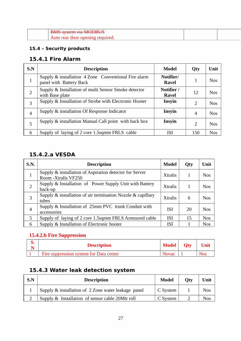
15.4 – Security products
15.4.1 Fire Alarm
S.N Description Model Qty Unit
1Supply & installation 4 Zone Conventional Fire alarm panel with Battery Back
Notifier/Ravel 1 Nos
2Supply & Installation of multi Sensor Smoke detector with Base plate
Notifier /Ravel
12 Nos
3 Supply & Installation of Strobe with Electronic Hooter Insyin 2 Nos
4 Supply & installation Of Response Indicator Insyin 4 Nos
5Supply & installation Manual Call point with back box Insyin
2 Nos
6 Supply of laying of 2 core 1.5sqmm FRLS cable ISI 150 Nos
15.4.2.a VESDA
S.N. Description Model Qty Unit
1Supply & installation of Aspiration detector for Server Room -Xtralis VF250
Xtralis 1 Nos
2Supply & Installation of Power Supply Unit with Battery back-up
Xtralis 1 Nos
3Supply & installation of air termination Nozzle & capillary tubes
Xtralis 6 Nos
4Supply & Installation of 25mm PVC trunk Conduit with accessories
ISI 20 Nos
5 Supply of laying of 2 core 1.5sqmm FRLS Armoured cable ISI 15 Nos6 Supply & Installation of Electronic hooter ISI 1 Nos
15.4.2.b Fire SuppressionS.N
Description Model Qty Unit
1 Fire suppression system for Data center Novac 1 Nos
15.4.3 Water leak detection system
S.N Description Model Qty Unit
1 Supply & installation of 2 Zone water leakage panel C System 1 Nos
2 Supply & Installation of sensor cable 20Mtr roll C System 2 Nos
27

15.4.4 Rodent repellent system
S.N Description ModelQuanti
tyUnit
1 Supply & installation of Rodent repellent panel C System 1 Nos
2 Supply & Installation of High frequency Transducer C System 12 Nos3 Supply of laying of 2 core 1.5sqmm FRLS cable ISI 250 Nos
15.4.5 BMS system
Sr. No. DESCRIPTION QTY UNIT
01Modbus based BMS system to connect the following equipments - With desktop PC
1 Set
02Chiller - 2Nos , UPS - 4Nos , PAC -1 , Racks cooling unit -1 , Fire alarm , Three power meter
15.5 – PAC Cooling unit
No. Description Qty Unit High Precision Air conditioners
1 Supply of Uniflair make PAC units (Bottom Discharge); DX-Air cooled PACs complete with direct drive motors and Fans with backward curved blades, Expansion Valve, Scroll Compressors for power savings, hydrophilic fins for IDU, fan speed controller for ODU, Water leak detector, Clock card, Sequencing and RS485 card supplied with the system. EU2/EU4 filters is provided. Unit offered will be suitable for eco friendly R407 C; Dirty filter alarm, heater, humidifier are part of the system. PAC will be pre-charged with N2.
4.5TR PAC units as per above specs. Max CFM @ 2905 / unit (PAC Units without Heater & Humidifier, with Thermostatic expansion valve and EU2 filters) 2 Nos
2 Low Side Works for High Precision AC Units Supply & Installation of MS stand suitable for raised floor of 400 mm clear height. 1 NosLeak testing and Refrigerant filling with R 407 C
64 KgPower cabling from indoor to outdoor units considering 18RMt per unit. 18 RMtCables for Sequencing of units, 10 RMt per unit 10 RMtHumidifier line (Consider 10RMT per unit) 10 RMtDrain line with insulation (Consider 10RMT per unit) 10 RMtCu piping interconnecting indoor and outdoor (20RMT per Ckt.) 15 RMt
28

Insulation of Copper pipe 15 RMt
15.6 – UPS for Pump
SL No UPS Specification 01 2 x 20kVA UPS 02 On Line double conversation UPS 03 IGBT Charger & Inverter 04 UPS operation in parallel mode.05 3 Phase input and single phase output 06 Input 415 V +/- 15% 07 Input voltage harmonic destruction less < 5% 08 Output Voltage 230V 50Hz 09 Efficiency above 92% at full load. 10 Each Battery bank to support 15mins at full 20kVA Load.
29