Embed Size (px)
Citation preview

THEIATelescope for Habitable Exoplanets andInterstellar/Intergalactic Astronomy
White Paper Submitted to NRC ASTRO-2010 Survey
Prof. N. Jeremy KasdinMechanical and Aerospace Engineering
Princeton Universitye-mail: [email protected]
phone: 609-258-5673
!"#$%&'()%*+,)-./0%'1)-+
Co-InvestigatorsPaul Atcheson, Matt Beasley, Rus Belikov, Morley Blouke, Eric Cady, Daniela Calzetti, Craig Copi, SteveDesch, Phil Dumont, Dennis Ebbets, Rob Egerman, Alex Fullerton, Jay Gallagher, Jim Green, OlivierGuyon, Sally Heap, Rolf Jansen, Ed Jenkins, Jim Kasting, Ritva Keski-Kuha, Marc Kuchner, Roger Lee,Don J. Lindler, Roger Linfield, Doug Lisman, Rick Lyon, John MacKenty, Sangeeta Malhotra, MarkMcCaughrean, Gary Mathews, Matt Mountain, Shouleh Nikzad, Bob O’Connell, William Oegerle, SallyOey, Debbie Padgett, Behzad A Parvin, Xavier Prochaska, James Rhoads, Aki Roberge, Babak Saif,Dmitry Savransky, Paul Scowen, Sara Seager, Bernie Seery, Kenneth Sembach, Stuart Shaklan, MikeShull, Oswald Siegmund, Nathan Smith, Remi Soummer, David Spergel, Phil Stahl, Glenn Starkman,Daniel K Stern, Domenick Tenerelli, Wesley A. Traub, John Trauger, Jason Tumlinson, Ed Turner, BobVanderbei, Roger Windhorst, Bruce Woodgate, Bob WoodruffIndustry Partners: Lockheed Martin Missiles and Space, ITT Space Systems, LLC, Ball AerospaceNASA Partners: Jet Propulsion Laboratory/Caltech, Goddard Space Flight Center, Ames ResearchCenter, Marshall Space Flight CenterUniversity Partners: Arizona State University, Caltech, Case Western Reserve University, Universityof Colorado, John Hopkins University, University of Massachusetts, University of Michigan, MIT, PennState, Princeton University, Space Telescope Science Institute, University of California-Santa Barbara,University of California-Berkeley, University of Virginia, University of Wisconsin, Yale University
1

1. THEIA Overview
Over the past 25 years, the Hubble Space Telescope has revolutionized our view of the universe,excited and engaged the general public with its compelling images, and has been a workhorse forastrophysics. We propose that NASA build THEIA, Telescope for Habitable Exoplanets and Interstel-lar/Intergalactic Astronomy, a flagship 4-meter on-axis optical/UV telescope as a worthy successorto HST and companion to the James Webb Space Telescope ( JWST). With a wide field imager, anultraviolet spectrograph, a planet imager/spectrograph and a companion occulter, THEIA is capableof addressing many of the most important questions in astronomy: Are we alone? Are there otherhabitable planets? How frequently do solar systems form and survive? How do stars and galaxiesform and evolve? How is dark matter distributed in galaxies and in the filaments? Where are mostof the atoms in the universe? How were the heavy elements necessary for life created and distributedthrough cosmic time?
In this white paper we describe the THEIA Observatory1, an on-axis three-mirror anastig-mat telescope with a 4-meter Al/MgF2-coated primary, an Al/LiF-coated secondary and threemain instruments: Star Formation Camera (SFC), a dual-channel wide field UV/optical imagercovering 19’ x 15’ on the sky with 18 mas pixels; UltraViolet Spectrograph (UVS) , a a multi-purpose spectrometer optimized for high sensitivity observations of faint astronomical sourcesat spectral resolutions, λ/∆λ, of 30,000 to 100,000 in the 100-300 nm wavelength range; andeXtrasolar Planet Characterizer (XPC), which consists of three narrow-field cameras (250-400nm; 400-700 nm; 700-1000 nm) and two R/70 integral field spectrographs (IFS).
There are many approaches to creating the needed contrast for exoplanet exploration, mostof which use either an internal coronagraph or an external occulter. Both have the potentialto yield similar exoplanet science (measured in number of planets discovered and characterized)with a 4 meter telescope, yet each has different technical challenges. For this study we focusedon an external occulter as a demonstration that a suitable mission architecture exists that canbe built in the next decade. This choice allows an on-axis telescope without wavefront con-trol, relaxes stability requirements, and simplifies the optical design and packaging for all of theinstruments. Nevertheless, we welcome a robust technology development program for bothcategories of starlight suppression.
THEIA’s companion occulter is 40 meters in diameter and stationkeeps at 55,000 km fromthe telescope for imaging from 400-700 nm and at 35,000 km to characterize from 700-1000 nm.While the occulter is on target (25% of mission time), XPC detects and characterizes extrasolarplanets and SFC does deep field science. While the occulter moves, THEIA conducts a richprogram of general astrophysics.
For the occulter/telescope system we anticipate three main tall poles: (1) building and de-ploying the occulter to demanding tolerances; (2) building a 4-meter telescope diffraction-limitedat 300 nm; and (3) building large focal plane arrays. We summarize plans, including cost andschedule, to advance technology readiness levels for each on a path toward flight system develop-ment. THEIA is a flagship class mission with an estimated life-cycle cost of $5 billion (including$0.9B reserve). The biggest development cost items are the telescope ($1.2B) and the instruments($0.8B).
1In Greek mythology, Theia is the Titan goddess of sight (thea), is also called the “far-seeing one”. She is themother of the Sun, the Moon and Dawn.
2
2. THEIA Science
THEIA is a multi-purpose space observatory operating in the optical/UV band. A successorto the Hubble Space Telescope, it will perform a broad range of science including exoplanetimaging and characterization, star and galaxy formation, and studies of the intergalactic medium(IGM) and the interstellar medium (ISM). Its three instruments enable an efficient and powerfulscience program. While the occulter is on target, XPC detects and characterizes planets andSFC deeply images adjacent fields. While the occulter is moving, SFC and UVS carry out a richprogram of general astrophysics. In our baseline design reference mission (DRM), we allocate25% of the prime mission observing time to each primary investigation, with the remaining25% allocated to a guest observer program.
Are we alone?
A primary goal of THEIA is to find and character-
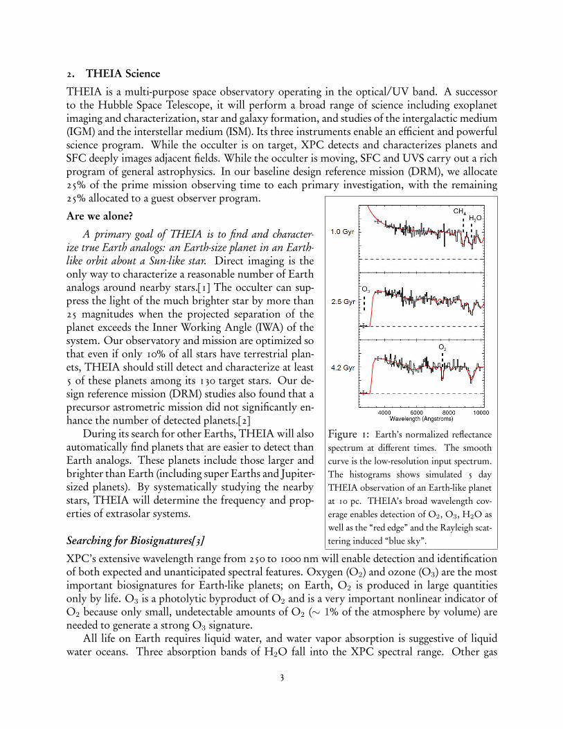
Figure 1: Earth’s normalized reflectancespectrum at different times. The smoothcurve is the low-resolution input spectrum.The histograms shows simulated 5 dayTHEIA observation of an Earth-like planetat 10 pc. THEIA’s broad wavelength cov-erage enables detection of O2, O3, H2O aswell as the “red edge” and the Rayleigh scat-tering induced “blue sky”.
ize true Earth analogs: an Earth-size planet in an Earth-like orbit about a Sun-like star. Direct imaging is theonly way to characterize a reasonable number of Earthanalogs around nearby stars.[1] The occulter can sup-press the light of the much brighter star by more than25 magnitudes when the projected separation of theplanet exceeds the Inner Working Angle (IWA) of thesystem. Our observatory and mission are optimized sothat even if only 10% of all stars have terrestrial plan-ets, THEIA should still detect and characterize at least5 of these planets among its 130 target stars. Our de-sign reference mission (DRM) studies also found that aprecursor astrometric mission did not significantly en-hance the number of detected planets.[2]
During its search for other Earths, THEIA will alsoautomatically find planets that are easier to detect thanEarth analogs. These planets include those larger andbrighter than Earth (including super Earths and Jupiter-sized planets). By systematically studying the nearbystars, THEIA will determine the frequency and prop-erties of extrasolar systems.
Searching for Biosignatures[3]
XPC’s extensive wavelength range from 250 to 1000 nm will enable detection and identificationof both expected and unanticipated spectral features. Oxygen (O2) and ozone (O3) are the mostimportant biosignatures for Earth-like planets; on Earth, O2 is produced in large quantitiesonly by life. O3 is a photolytic byproduct of O2 and is a very important nonlinear indicator ofO2 because only small, undetectable amounts of O2 (∼ 1% of the atmosphere by volume) areneeded to generate a strong O3 signature.
All life on Earth requires liquid water, and water vapor absorption is suggestive of liquidwater oceans. Three absorption bands of H2O fall into the XPC spectral range. Other gas
3

absorption features, including the potential biosignature methane, are present in the XPC wave-length range. Methane would be detectable if present in much larger quantities than on Earth,potentially in the atmospheres of super Earths and mini-Neptunes.
With multiple visits and extended integrations for characterization, XPC should detect pho-tometric variability. These observations could lead to a measurement of the planet’s rotationrate, detection of weather, and even the inference of continents.
Design Reference Mission and Science Optimization
In our study, we used a Monte-Carlo based Design Reference Mission (DRM) generator[2] tocompare the scientific effectiveness of three different terrestrial planet finding approaches using a4m telescope: (1) a coronagraph with the optimistic assumption of a 2 λ/D inner working angle;(2) a 52 m diameter occulter with 19 m petals flown 70,400 km from the telescope (occulter edgeIWA of 75 mas and a 50% throughput angle of 60 mas and (3) our baseline design of a 40 mdiameter occulter with 10 m petals that has the same IWAs for 250-700 nm when flown 55,000km from the telescope, but does longer wavelength characterization (700-1000 nm) by movingcloser to the telescope (edge IWA of 118 mas). Since the planet spends a significant fractionof its orbits at smaller separations, minimizing the IWA enables more planet detections andcharacterizations. We also strove for the smallest occulter possible; a smaller occulter bringsmany benefits, including lower mass (allowing more fuel), easier deployment, better packagingin the launch vehicle, lower fuel use, more rapid retargeting maneuvers, and easier testing.
0.1 0.2 0.3 0.4 0.5 0.6 0.7 0.8 0.9 1
5
10
15
20
25
30
35
40
!"
Unique Planet Detections
CoronagraphOcculterTHEIATHEIA Extended
(a)
0.1 0.2 0.3 0.4 0.5 0.6 0.7 0.8 0.9 1
5
10
15
20
25
30
35
40
45
!"
Spectral Characterizations to at least 700nm
CoronagraphOcculterTHEIATHEIA Extended
(b)
0.1 0.2 0.3 0.4 0.5 0.6 0.7 0.8 0.9 10
5
10
15
20
25
!"
Spectral Characterizations between 250 and 1000nm
CoronagraphOcculterTHEIATHEIA Extended
(c)
Figure 2: The performance for four DRMs: (1) 2 λ/D coronagraph; (2) a single distance 52 m occulter; (3) baselineTHEIA design and (4) an extended mission. The left figure (a) shows the number of unique planet detections. Thecenter figure (b) shows the total number of planets characterized at λ < 700 nm; the right figure (c) shows the totalnumber of planet characterized over the full wavelength range for the different DRMs.
Figure 2 shows that the different approaches yield a comparable number of unique planetdetections. Because of its inner working angle advantage at 700 < λ < 1000 nm, the singledistance occulter obtains more full spectral characterizations (thus finding oxygen and water onmore planets). However, the larger occulter has several disadvantages as well: the additionalmass limits the mission to at most 5 years (assuming an Atlas V launch vehicle), at which pointit runs out of fuel. The petals are significantly longer, greatly complicating packaging (no designcurrently exists that fits in the available 5m fairings). Manufacturing tolerances on the largerocculter are more challenging. The limited fuel also severely curtails its ability to revisit discov-ered planets and determine orbits. For our extended mission DRM, we chose to prioritize orbit
4

characterization and found that the smaller occulter provides good orbital fits in 5 systems byrevisiting each system at least 4 times and achieving 10% period determination.
The choice between the occulter and coronagraph comes down to technical readiness, risk,and cost. An occulter introduces formidable manufacturing, deployment and test challenges, aswell as the dynamics and control problems associated with positioning and slewing the occulter.The coronagraph presents its own challenges associated with a large, off-axis, UV-diffraction-limited telescope with exquisite stability requirements, a small IWA coronagraph, and a wave-front control system. We also explored hybrid approaches that might share the burden ofstarlight suppression between the two systems, but concluded that the alignment requirementson the occulter in the hybrid system were too severe. While both coronagraphs and occulterswarrant careful study, for our point design we chose the occulter system because of its simplertelescope, unlimited outer working angle, and the fewer challenges associated with packagingthe multiple instruments.
Transiting Planets
One of HST’s important (and unanticipated) uses has been the characterization of the atmo-spheres of two of the fifty-eight known transiting planets.[4] THEIA tremendously expands thiscapability; the UVS instrument will perform FUV transit spectroscopy on a much larger set oftargets and enable the detection of strong transitions of abundant atomic and molecular species,including H, C, N, O and H2. With future surveys likely to find even more targets includ-ing possible super-Earths, THEIA’s FUV capabilities will be an important complement to ourdirect imaging program.
How do planets form?[5]
With its starlight suppression system, THEIA will make the most sensitive inventory and de-tailed images of protoplanetary and debris disks possible with any planned or existing telescope.THEIA will trace the formation and rearrangement of small body belts, sense otherwise un-detectable planets via disk patterns and probe structure and composition throughout, revealingthe environments where terrestrial planets form, migrate, and receive their important final doseof volatiles.
How do stars form in galaxies across time and environments?
Understanding the physics of star formation is another major theme for the THEIA mission.We designed a four-tiered program of observing star formation on different scales that utilizesthe SFC and UVS instruments. Within our own Galaxy (Tier 1), SFC will image all high-massstar formation sites within 2.5 kpc of the Sun (∼ 41 deg2) covering the full range of apparent starformation (SF) modes and environments.[15] The observations will be complemented by UVSspectral observations of specific star formation regions.[6] Our SFC dataset will resolve billionsof individual stars and detect circumstellar material and associated jets and shocks around manystars.
On the local group scale (Tier 2), we plan a complete SFC imaging survey of the MagellanicClouds and star-forming galaxies in 8 broadband and 4 narrow-band emission line filters.[7] Thegoals are to take a complete a census of the richly varied stellar populations, to investigate feed-back from massive stars in both HII regions and in the diffuse warm ISM, and to quantitativelyparameterize stellar clustering and star formation propagation. We will determine how giant
5

star-bursting HII regions differ from smaller HII regions within the Milky Way, and determinethe impact of metallicity on star formation by comparing a set of 21 similar HII regions of 0.1Z� in the Magellanic Clouds with counterparts in the Milky Way using additional filters toprovide nebular diagnostics.
Moving outward, we plan a deep survey of 100 galaxies and a medium-deep survey of 500local galaxies in narrow and broadband filters that span the 190-1075 nm wavelength range (Tier3).[9] We aim to understand these galaxies as a whole through their resolved and unresolved stars,ISM, and immediate environments (“near field cosmology”). Stellar populations will be analyzedusing color-magnitude and color-color fitting and population synthesis modeling to providespatially resolved star formation histories; the ISM will be studied to understand the energeticsources and effects of metallicity and galactic environment. The combination of medium anddeep surveys will provide statistics over the full parameter space of physical conditions andenvironments.
Lastly, in SFC’s Tier 4 survey, [10] we will conduct a panchromatic imaging survey of cos-mological targets across wide fields covering ∼ 10 deg2 in two epochs to AB < 28 mag and∼ 1 deg2 in 20 epochs to AB < 30 mag. The survey will provide spectrophotometric redshiftsaccurate to within 2% and will measure faint source variability for 5 million galaxies.
Deep parallel imaging taken during the long (up to 50 day) integrations on planetary targetswill complement the wide field survey. For a four filter imaging survey covering 550-1100 nm,SFC will integrate to a depth of > 2.0 mag greater than the Hubble Ultra Deep Field with over25 times the area in each parallel mode integration.
Figure 3: UVS’ slit capability allows spatially resolved spectroscopy of transiting planetary atmospheres, circum-stellar disks, starburst galaxy outflows, and active galactic nuclei. Because its wavelength coverage extends down to1000 Å, UVS can measure key diagnostics of coronal gas (O VI), massive star winds (O VI, P V, S IV), molecular gas(H2), planetary atmosphere markers (O I, C II), and neutral hydrogen (Ly-β). Extensive wavelength grasp in singleexposures increases the number of diagnostics available for studies requiring information at multiple redshifts, suchas the IGM, or needing broad spectral coverage, such as stellar atmospheres and AGN.[11]
Tracing the evolution of the IGM[11]
At the core of the UVS science program is a comprehensive investigation of the cosmic web, therepository for most of the baryons in the universe and the raw material for galaxy formation.A primary challenge in the next decade is to advance beyond simple detections of the cosmicweb gas to determine how the cosmic web is organized, how it has changed with time, andhow it has been assembled into galaxies. The UVS cosmic web survey will do exactly this, byobserving the intergalactic absorption toward 250-500 QSOs at redshifts of 0.2-1.0. The surveywill result in the detection of thousands of O VI absorption systems, and tens of thousands ofLy-α absorption systems, along with accompanying metal lines providing information about the
6

ionization, composition, and metallicity of the gas. The total redshift path probed along thesesight lines will exceed that observed by HST/COS by at least a factor of 10. Combining thesedata with galaxy redshifts and UVS observations of the gas in the immediate environments ofgalaxies will provide a deeper understanding of how galaxies and the universe evolve.
UVS will observe the He II Gunn-Peterson absorption and its transition to the He II Lyman-α forest in multiple directions to gain a detailed picture of the complete reionization of theuniverse and the structure growth at z∼ 3. SFC’s Tier 4 survey will yield escape fractions ofUV photons from high redshift objects and the contribution of dwarf galaxies and Ly-α emittersto the UV flux.
Dark matter and dark energy
SFC’s spatial resolution and positional accuracy will revolutionize strong lensing studies ingalaxies and clusters by improving dark matter substructure mass limits by two to three ordersof magnitude. This will constrain warm dark matter models. SFC will also enable a tripling ofthe number of detected lensed sources in a typical field cluster. High-precision measurements ofthe positions of multiple images deriving from the lensing of sources at different redshifts by asingle cluster lens will provide important independent means of measuring the geometry of theuniverse and the dark energy properties. UVS measurements of the cosmic web complementthese observations by measuring the matter power spectrum at small scales.
Unanticipated discoveries
This section has outlined a number of the possible astrophysical applications of THEIA ob-servations identified in this study. Nevertheless, the track record of HST suggests that manyof THEIA’s most important discoveries will be unanticipated. With its suite of powerful in-struments and a spatial resolution more than double that of HST and JWST, THEIA will be apowerful tool for quick follow up of targets discovered by LSST, Pan-STARRS, LIGO, and otherupcoming large-surveys. Just as HST’s imaging and UV capabilities have complemented Keckspectroscopy, THEIA will complement JWST, ALMA and the next generation of ground-basedtelescopes.
Science Requirement Performance Requirement Design
Detect Earth twin at 10 parsec Detect Earth twin at 10 parsec 40m occulter for starlight suppression over 0.4-1um band.Detect ≥ 1 HZ planet with 95% confidence, if 30%
of target stars have planets Contrast ≥ 26 mags
IWA ≤ 75 mas
40m occulter for starlight suppression over 0.4-1um band.
Detect Jupiter twin at 10 pc OWA ≥ 500 mas No restriction, not a design driver
Measure planet brightness within 10% Contrast stability ≥ 28 magsMain driver to occulter stability
Measure planet brightness within 10% Contrast stability ≥ 28 mags 1 mm stability at tip, 100 um petal deformationMeasure planet brightness within 10% Contrast stability ≥ 28 mags100 mK PM stability
Detect atmospheric O2, H2O, O3
Bandpass = 0.5 to 1.0 µm 2 broadband science channels feed 2 IFUs UV Ozone Camera - 4m aperture for throughput.Detect atmospheric O2, H2O, O3
Spectral resolution ≥ 702 broadband science channels feed 2 IFUs UV Ozone Camera - 4m aperture for throughput.
Survey formation & evolution of stars & galaxies with red-shifts up to 9
FOV = 15' x 19'Star Formation Camera with 2 channels High efficiency detectors & large focal planes 6 Tbytes/day after x2 loss-less compression
Survey formation & evolution of stars & galaxies with red-shifts up to 9
Pixel FOV = 18 masStar Formation Camera with 2 channels High efficiency detectors & large focal planes 6 Tbytes/day after x2 loss-less compression
Survey formation & evolution of stars & galaxies with red-shifts up to 9
Diffraction limited to 10' off-axis
Star Formation Camera with 2 channels High efficiency detectors & large focal planes 6 Tbytes/day after x2 loss-less compression
Survey intergalactic web & investigate galactic interactions & effect on evolution
Bandpass = 100 to 300 nm Spectral resolution ≥ 30,000
UV Spectrograph with 2 channels on-axis entrance at Cassegrain-like focus LiF coated secondary mirrorNo extra reflections - UVS extends into bus
Table 1: Theia Science Requirements
7

3. THEIA Technical Overview
The THEIA system design is an answer to the scientific challenges posed above, combining ex-oplanet discovery and characterization with general astrophysics into a single mission architec-ture. The mission consists of two spacecraft, a 4-m primary telescope at the Sun-Earth L2 pointwith a suite of three primary instruments, the eXoPlanet Characterizer (XPC), the Star Forma-tion Camera (SFC), and the Ultraviolet Spectrograph (UVS), and an occulter spacecraft flyingin formation to maintain sufficient starlight suppression for the required exoplanet science. Ourdesign for THEIA satisfies all of our science requirements with large technical margins, fits ontwo Atlas-V launch vehicles, and has a cost and schedule profile consistent with a launch latein the next decade. The prime mission duration is 5 years with a 10-year life goal. Earth com-munication and navigation tracking is via S-Band and Near-Earth Ka-Band channels of the 34 mDSN.
The THEIA observatory is a natural evolution from HST and JWST. The 4-m, on-axistelescope, and attached instruments, is mated with a conventional spacecraft system. The ob-servatory is 3-axis pointed within 3 arcsec using reaction wheels with hydrazine thrusters formomentum desaturation and stationkeeping. The telescope bore-sight is pointed to within 30milliarcsec using active struts and the final beam is pointed to within 4 mas using fine steeringmirrors (FSMs). Sensing is accomplished through a combination of rate gyros, fine guidance sen-sors, and star trackers. The observatory communicates with the occulter spacecraft and Earthusing separate S-band links. The observatory can downlink up to 6 TBytes of data per day witha 1 Gbps downlink rate and 12 TBytes of storage. The observatory has a maximum expectedmass of 5,700 kg as compared to a launch mass capacity of 6,300 kg. Observatory solar arraysare conservatively sized for 5kW of power at end of life, providing large margins.
The occulter system, with starshade shown later in
Figure 4: The occulter spacecraft system.
Figure 9 and attached spacecraft shown in Figure 4, con-sists of a 40-meter starshade attached to a spacecraft busequipped for repositioning, stationkeeping, and point-ing. The solar array is sized for 15 kW of end of lifepower to accommodate 2 NEXT-Ion thrusters firingsimultaneously at maximum power (which can be ad-justed in flight) plus 1 kW for other bus equipment.This thruster subsystem consists of 6 total thrusterswith 3-for-2 redundancy on each side of the starshade.During exoplanet observations, the occulter system isheld on targets constrained to lie between 45 and 85degrees from the sun line to avoid stellar leak into thetelescope or reflections off the starshade. Stationkeeping does not employ electric thrusters be-cause they produce a bright plume potentially contaminating the observations. The spacecraft isthus also equipped with a set of on/off hydrazine thrusters that control position to within ±75cm. A shutter is employed during the short, infrequent hydrazine pulses to avoid light contami-nation from the plume. After a retargeting slew, the observatory/occulter formation is acquiredin 4 overlapping stages of position sensing: 1) Conventional RF Ground tracking (±100 km),2) Observatory angle sensing of a Ka-Band beacon from the occulter spacecraft (±16 km), 3)XPC IR imaging of a laser beacon (±70 m) and 4) XPC IR imaging of light leaking around the
8

occulter (±35 cm). The Observatory measures occulter range via the S-Band link. The occultersystem has a maximum expected mass of 5,700 kg as compared to a launch mass capacity of6,300 kg. The remaining mass margin will be used for additional fuel for extended operations.
Telescope and Instrument Accommodations
THEIA’s telescope is an on-axis three mirror anastigmat (TMA) optical design with a 4 m aper-ture and diffraction limited performance to 300 nm. The design highly leverages a 2m class OTAdynamic testbed design that is traceable to space hardware developed at ITT Space Systems Di-vision, LLC. Overall, the design corresponds to a Korsch system with a primary/secondarycombination similar to a Cassegrain telescope. There is a different set of tertiary optics for eachinstrument. The driver for the overall telescope configuration is the need for a large, diffractionlimited field-of-view for the Star Formation Camera. Figure 5 shows a trace of the light paths tothe various instruments. The UVS instrument is fed a narrow on-axis beam near the Cassegrain-like focus with reflections limited to the primary and secondary mirrors. The SFC and XPCinstruments are fed off-axis beams and include additional powered and aberration-correctingoptics.
The relatively slow f1.5 Primary Mirror (PM) is a stiff, lightweight, closed-back designconstructed of Corning Ultra Low Expansion (ULE R©) glass with an Al/MgF2 coating. Thesegmented lightweight honeycomb core is joined to the lightweighted pocket-milled mirrorfacesheets using a low temperature fusion process. The PM is polished and final ion beamfigured to a rms wavefront error less than 15 nm, only slightly better than Hubble’s primarymirror (∼ 20 nm). All PM processes have heritage from smaller mirrors and will be demon-strated on a sub-scale prototype. Areal density is conservatively specified at 50 kg/m2, a safeprogression from the current state of art.
The Secondary Mirror (SM) mounts to a hexapod
UV Planet Cam
XPC
Red Channel517 – 1100 nm
Blue Channel190 – 517 nm SFC
NUV170 - 300
nm
FUV100 – 170
nm
UVS
TertiaryMirrors
(4 places)
Coarse OcculterTracking Cam
Telescope (F16)
Fine OcculterTracking Cam
VIS Planet CameraIFU
NIR Planet CameraIFU
< 400 nm
400 – 700nm
700 – 1100nm
50%> 1100 nm
> 1100 nm
Figure 5: The telescope light paths.
actuator that enables calibration of pointing and fo-cus, though, due to the precision composite meteringstructures, SM re-alignments will be very infrequent.A global correction is applied with additional correc-tions in the SFC and XPC instruments so that all in-struments can be operated without adjusting the SM.The secondary mirror is Al/LiF coated for high reflec-tivity in the Far-UV. A dry nitrogen purge is applied tothe SM throughout ground operations to avoid moisture degradation.
The instruments are kinematically mounted to the PM backing structure. The OTA preci-sion metering structures coupled with a fairly simple thermal control system are able to keepthe optics in alignment to the required tolerances. The composite metering structures are fabri-cated using fibers and a state-of-the-art cyanate siloxane resin system (co-patented by ITT). ITT’sexperience in using these materials result in metering structures that have thermal stability ofthe same order of magnitude as ULE R©glass with nearly negligible hygroscopic effects. Theintegrated payload mounts to the spacecraft with piezo-actuated struts that provide vibrationisolation and precision pointing of the bore sight. Active struts are conservatively included tosimplify spacecraft pointing, but may not be necessary (HST achieves our specification withoutthem). Active struts have been demonstrated on ITT testbeds and have a TRL of 6 or better.
9

Star Formation Camera (SFC)
The SFC instrument, shown in Figure 6, is a wide-field imager with an unprecedented combi-nation of FOV (19’ x 15’) and resolution (18 mas). Final resolution is diffraction limited at 300nm, but camera size is reduced by under-sampling at the diffraction limit. Critical sampling isreconstructed on the ground from multiple images with dithered pointing, using fast steeringmirrors (FSMs) within the instrument.
A dichroic splits the beam at 517 nm into simul-
Figure 6: The SFC Optical Layout.
taneously operated red and blue channels, for efficientobserving. Each channel includes a tailored set of band-pass filters and a shutter.
The SFC uses Lawrence Berkeley Laboratory’s CCDdetectors, with 10.5 micron pixels and a 3.5K squareform-factor. A tertiary mirror within SFC produces anf/30 beam to match the plate scale. Each focal planearray (FPA) consists of 18 x 15 detectors and is 66 x 55cm in size. They are passively cooled to 170 K and usethermal baffles to limit parasitic heating. Each detectoris packaged with modular electronics for fault isolationand rapid change out. Detectors are extensively processed (thinning, AR coating, delta-doping,etc.) to optimize photometric efficiency.[15] JPL’s Giga-pixel Initiative is developing techniquesthat could be applied to the production and test of the SFC flight detectors.
Exoplanet Characterizer (XPC)
The XPC instrument suite consists of UV, Visi-
Figure 7: The XPC Optical Layout.
ble, and NIR science cameras, coarse and fine occultertracking cameras (FOTC), and two Integral Field UnitSpectrometers. They are all fed by a 0.1 deg off-axisbeam and picked off just before the Cassegrain focus.The optics operate at room temperature while the de-tectors are cooled to 150 K. Figure 7 shows a schematicof the instrument without the visible light channel forclarity. A series of dichroic mirrors split the light asshown. The Ozone Camera uses 2 aspheric optics toform an f/90 beam, corrected over a 10” field. The to-tal number of reflections in this instrument, including the primary and secondary telescopemirrors, is five. The beam is Nyquist sampled on the detector at a wavelength of 250 nm. IRlight up to 2 µm is passed to the f/6.5 COCT which has a 3’ field and 1” pointing precision to lo-cate the occulter laser beacon and feedback position information for handoff to the FOTC (f/60,20” field, 4 mas resolution). Visible and NIR light is split between two science channels (400-700and 700-1000 nm), each with a filter wheel for spectrophotometry, a fine guiding mirror forbeam stabilization, and a flip-in mirror to fit the IFUs. These science channels are identically de-signed to form an f/60 beam with a diffraction-limited 10” field and > 80% throughput on e2VTechnologies L3CCDTM. The visible/IR cameras will be the exoplanet detection workhorses.They each have 8 reflections including the PM, SM, dichroic, two OAPs, 2 folds, and an el-
10

lipse, all easily fabricated. Based on the TPF-C CorSpec design,[13] the IFSs have a 134 x 134microlens array to obtain an R∼70 spectrum, again using L3 CCDs. We note that while allof our DRM studies were performed with conventional CCDs, the planet characterization sci-ence would greatly benefit from development of radiation hardened, zero read noise, high QEphoton counting detectors in the NIR (700 to 1000 nm).
Ultraviolet Spectrograph (UVS)[12]
The ultraviolet spectrograph (UVS), shown in Fig-
Figure 8: The UVS Optical Layout.
ure 8, performs studies of gas ionization, composition,and dynamics in systems ranging from cosmologicalscales (the intergalactic medium) to planetary scales (ex-oplanet and solar system bodies). UVS is optimizedfor high sensitivity observations of faint astronomicalsources at spectral resolutions, λ/∆λ, of 30,000 to 100,000in the 100-300 nm wavelength range. The UVS has asingle instrument enclosure, which includes all neces-sary subsystems (heaters, electronics, calibration plat-form, etc.) in addition to optics, detectors, and mechanisms. The spectrograph is located on-axisand receives light directly from the telescope secondary mirror through an entrance apertureand slit mechanism. Light can enter one of two channels. Light entering the far-ultraviolet(FUV; 100-170 nm) channel encounters a single Al/LiF coated, holographically ruled, 1st-orderdiffraction grating that focuses and disperses the light onto a long, curved, photon-counting mi-crochannel plate detector array. Light entering the near-ultraviolet (NUV; 170-300 nm) channelis collimated by an optic behind the slit wheel that is placed into the incoming beam. Thecollimated light is then reflected to one of several echelle gratings, followed by a selectable cross-disperser and a camera mirror before being recorded by a flat 8K x 8K photon-counting CCDarray. For both channels, the entire spectral bandpass of the channel is recorded in each expo-sure. Spectral dithering is available for high S/N observations. Selectable slits and apertures areavailable for both channels, including long slits for spatially resolved spectroscopy.
The UVS instrument design was refined and costed by the Integrated Design Center atGSFC. The UVS could be built today with existing technology (all at TRL 6), but wouldbenefit significantly from technology development in the following areas: large-format photon-counting UV detectors (MCPs and CCDs) with quantum efficiencies > 60-80%; better UVreflective coatings with > 65-70% reflectivities between 100 and 300 nm; and large, efficient,aberration-correcting gratings with low scatter.
Occulter System
Starlight suppression for THEIA is accomplished via a large external starshade with an opti-mized shape[14] that results in a diffraction pattern at the telescope sufficiently dark for planetdetection and characterization, as shown in Figure 9. A modular construction approach em-ploying petals deployed around a fabric core was developed by study partner Lockheed MartinSpace Systems leveraging past experience in large deployable space structures. The starshade iscomprised of 2 major subsections, a 19.46 m diameter inner core composed of 3 layers of Kap-ton and an outer section of twenty 10.27 meter tall and 3.7 meter wide petals. Together, whendeployed they form an occulting mask 40 meters in diameter from tip-to-tip.
11

Petals (20)
~40m
~20m
Inner kapton Assy
Graphite epoxy box frame
Deployment deck
Figure 9: The Occulter Starshade
The precision shaped petal edge, definedfor maximum light suppression, is machinedinto an extremely low CTE graphite epoxysheet. The sheet is bonded to a petal perime-ter graphite epoxy box frame to provide struc-tural support. In the stowed configuration,the central core and petals mount to a graphitecomposite deployment deck, which in turnmounts to the spacecraft. A central open-ing accommodates the recessed mounting ofpropulsive thrusters, antennas and laser bea-cons. The stowed configuration fits inside a 5m launch fairing with margin. A truss struc-ture supports the stowed petals and is jettisoned after launch. Deployment is initiated by ex-tending the entire stowed petal stack on two deployable booms. This linear action unfoldsthe center-blanket assembly. Once fully extended, the booms begin a rotation that initiates se-quential deployment of the petals. All petal hinge lines are controlled by redundantly actuated,passively damped, high accuracy hinges. A simple sequencing cam between the primary hinge-lines of the petals also controls deployment. As the booms rotate, the petals unfold. The finalposition is controlled by stops designed into each hinge line. Careful optical analysis was usedto design the hinges and gaps to maintain the needed starlight suppression.
The occulter design effort was based on the use of flight proven mechanisms for implemen-tation of a precision deployment sequence using the ADAMS code in an interactive mode todefine precision damping and torque rates to verify petal contact is avoided during unfurling.Manufacturing methods have been defined including tooling and facilities needed for componentfabrication.
Petal Position or Shape Error Allocation
r.m.s shape (1/f2 power law) 100 µmProportional shape 80 µm at max widthLength clipping at tip 1 cmAzimuthal position 0.003 deg (1 mm at tip)Radial position 1 mmIn-plane rotation about base 0.06 deg (1 cm at tip)In-plane bending (r2 deviation) 5 cmOut-plane bending (r2 deviation) 50 cmCross-track occulter position 75 cm
Table 2: Starshade Tolerances.
Meeting the science requirements for planet charac-terization requires an occulter design with starlight sup-pression of 1×10⁻¹¹ and scattered light calibration to acontrast of 6× 10⁻¹². Using new modeling tools devel-oped by NASA’s Exoplanet Exploration Program, wehave analyzed the occulter starlight suppression perfor-mance and find that it is robust against motions and de-formations. Our modeling approach combines an ana-lytic solution for the occulter field at the telescope witha near-field diffraction model of the optical system. Per-formance is evaluated at the inner working angle in thetelescope focal plane. We considered the likely petalmanufacturing, deployment, and deformation modes, as well as the star-occulter-telescope line-of-site requirement. Table 2 shows the tolerances needed to meet the contrast stability goals atthe inner working angle of 75 mas. The manufacturing tolerance can be relaxed if the deploy-ment accuracy exceeds the indicated values. A careful thermal-mechanical analysis is in progress,coupled with the optical propagation code, to confirm contrast is maintained during expecteddynamic and thermal environments.
12

4. Three Most Significant Technology Challenges for THEIA
Large Telescope Optics
THEIA’s primary mirror (PM) is a 4m on-axis monolith with an areal density of 50 kg/m2
and less than 15 nm of wavefront error, r.m.s. By comparison, Hubble’s PM is a 2.4 m on-axismonolith with an areal density of 160 kg/m2 and about 20 nm of wavefront error, r.m.s. Bythis comparison, the THEIA PM appears to represent a large technological challenge. However,significant advancements have been made since the Hubble PM was fabricated in the areas ofmirror design, fabrication, and polishing which significantly reduce technology risk, and essen-tially turns the task of fabricating the THEIA PM from one of pure technology development toone of a challenging engineering exercise. These existing developments include:
1. Abrasive Water Jet (AWJ) cutting to aggressively lightweight a mirrors’ core.2. The invention of Low Temperature Fused (LTF) Corning ULE R©mirror blanks.3. Segmented core fabrication that reduces manufacturing time and risk of breaking a full-
sized fragile core.4. Pocket milled face-sheets that significantly reduces overall mirror weight.5. Computer controlled active laps polishing of highly aspheric optics.6. The combination of pocket-milling and deep segmented AWJ cores.7. Technology advancement in optic and telescope metrology.
Many of these new processes have already been employed on existing programs such asIkonos, Nextview, AMSD, TDM, and AFRL DOT.
Nevertheless, because the THEIA PM is large, relatively expensive, and not completelywithout risk, the THEIA plan is to develop a sub-scale prototype to demonstrate all processesprior to entering Phase C. We have allocated $50M for this technology development. A subscalepolishing demonstration will be used to confirm that the THEIA PM smoothness requirementscould be met on a mirror of comparable stiffness. Development of a full-scale blank was alsoconsidered but deemed not necessary by our study partner, ITT Space Systems Division, LLC.Rather, a proto-flight unit will be used to qualify the design, as is the case for most of the opticalsystems developed by ITT. Witness samples will be processed in parallel with the flight unit andcertified by optical inspectors at multiple points in the process.
There are other mirror technologies that could be developed to lessen the risk, cost andschedule for the THEIA PM, but they are not deemed essential. These include:
1. ULE R©welding could enable a large blank to be built up from smaller pieces.2. ULE R©large boule development would reduce the schedule required to produce all of the
glass required for large monolithic mirrors.3. ULE R©Striae (visibly detectable layers in the glass) are developed as a result of non-uniformities
in the distribution of titanium oxide molecules which are introduced into the material tominimize the materials coefficient of thermal expansion. When ULE R©is polished, thenon-uniformities in the striae layers can result in high spatial frequency surface errors thatcould adversely impact the system performance of a telescope.
13

Large Focal Plane Arrays[15]
Large focal planes are essential to achieving the SFC science program introduced in the sciencesection and outlined in a series of white papers [6, 7, 15, 9, 10]. The SFC Team-X study hasyielded invaluable insight into cost and yield, as well as the likely problems associatedÊwith theproduction and testing of the many CCD chips in the two SFC focal planes (∼ 540 flight-rateddevices).
This section outlines the technological challenges associated with building these large focalplanes. The investment in low-risk, low-cost, high-fidelity assembly and integration of large focalplane arrays will benefit not only the THEIA mission but also other future imaging missions.
There are several issues associated with large chip production:
1. The need to mass produce large numbers of chips with low read noise, low dark currentand high yield from modern lot run manufacture;
2. The requirement to test large numbers of detectors while preserving the fidelity of theproduct and mitigating the risk associated with fabricating the final array;
3. The need to develop new packaging designs to minimize interchip gaps when mosaicinglarge numbers of detectors;
4. The need to develop high-capacity data storage, compression and transmission technology.
As part of this development process, we advocate a critical assessment of specifications forflight-rated detectors appropriate for the era of mass production. We have outlined a technol-ogy development path that will enable a production line environment that will be capable ofproducing 540 separate flight-read detectors for the twin FPAs:
1. Complete the infrastructure for processes and facilities (detectors, readout, packaging) (1year)
2. Fabricate and validate prototype detector modules (SCA) - procure ASIC readout chips,procure detector fabrication run at foundry, process wafers at JPL, design packaging. De-velopment and fabrication of 10 units, testing and qualification of the module (2 years)
3. Fabricate, validate and demonstrate at a ground observatory a prototype 3x3 raft module(SCA) - procure ASIC readout chips second iterative lot, procure detector fab run, processwafers at JPL, design packaging. Development and fabrication of 2 units, cold flatness test,shake and bake, radiation, observation including dewar, thermal, miscellaneous additionalinstrumentation, ( two years)
4. Fabrication and validate prototype FPA by assembling two rafts (SCA) (1 year)
5. Fly a balloon demonstration (parallel with above steps 2-4). Overall schedule is four yearsfor first flight with a second flight in the fifth year. Overall ROM cost is $40M.
14

Occulter Technology Challenges and Test Program
One of the major technology challenges of THEIA is verifying the starlight suppression modelsand confirming that the occulter can be manufactured and deployed to the required tolerances.While optical models predict the desired contrast, verification that the scalar theory and othermodeling steps are sufficient is necessary. Current work is underway at Princeton and elsewhereto perform laboratory scale tests of occulting masks and to determine their sensitivity. Worksuch as this at varying scales needs to continue.
The occulter starshade design employs existing materials and mechanical components butthe petal deployment system as a whole is currently considered to be at TRL 3. Note howeverthat a recent successful deployment testing of a 37.5 x 37.5 m panel demonstrated damping andspring rates comparable to THEIA’s starshade. Our planned technology development programincludes subscale deployment testing of a 3 petal set, a full compliment of subscale petals andcharacterization testing of thermal and dynamic responses used to validate analytical models thatare used to predict the behavior of a full-scale system. Material testing will also be performed,including verification of CTE performance (a critical parameter for the graphite epoxy edges).The technology program will include the development of test equipment for gravity off-loadingand an interferometric system to measure petal positions.
The sub-scale 1g development program consists of constructing and deploying three, 1/4-scale petals. Full scale, high accuracy hinges will be used to obtain deployed geometry andalignment measurements consistent with a full-scale design. This test program will be conductedin ambient and thermal vacuum conditions, and will be used to develop manufacturing, tooling,handling, deployment precision, deployed geometric stability, and measurement methods.
The KC135 0g deployment program will consist of deploying eight, 1/20-scale petals in anairplane flying parabolic arcs in order to simulate a 0g environment. This development programwill focus on evaluating deployment sequence, deployment repeatability, and deployment times.Adjustments to sequence timing, damp rates, and torque rates will be evaluated over the courseof several deployments. Video measurements of deploy time and character will be used tocorrelate dynamic modeling.
A 1/5-scale occulter with a full complement of petals and blankets, full scale high accuracyhinges, and 1/5-scale precision deployable masts will be deployed on a sounding rocket in anear 0-g, vacuum environment. Hinges will be instrumented to provide deployment telemetry.Retro-reflective targets will be video-taped during deployment providing additional telemetryto evaluate deployed alignments. This same 1/5-scale starshade system is deployed in a thermalvacuum chamber for more accurate measurements and performance verification over the oper-ating temperature range. This test will also provide experience with the gravity off-loading testthat will be scaled up for testing a full scale occulter. The total cost estimate for our starshadedevelopment to TRL 6 is $40M.
We also plan to prepare a full-scale qualification unit. In addition to environmental quali-fication testing, we will use this qualification unit to deploy a 3 petal set in a thermal vacuumchamber for further verification of analytical models. We have also defined a test plan for de-ploying the full-scale qualification unit with full compliment of petals in an available hangerfacility. This latter test is proposed but is not included in our current cost estimates.
15

5. Activity Organization, Partnerships, and Current Status
This project grew out of an NASA Advanced Stragetic Mission Concept Study (ASMCS). Ourteam consists of scientists and engineers at Princeton Univeristy, The Space Telescope ScienceInstitute (STScI), Arizona State University (ASU) and many other partner universities, NASAcenters (JPL/Caltech, GSFC), and industry partners (Lockheed Martin Missiles and Space, BallAerospace, and ITT Space Systems LLC).
The chart in Figure 10 shows the projected schedule for mission development with a launchat the beginning of 2021. The three tall pole technology items are emphasized. An immediateinvestment in technology development is essential to meet this schedule.
Calendar Year
Fiscal Quarter 2 3 4 1 2 3 4 1 2 3 4 1 2 3 4 1 2 3 4 1 2 3 4 1 2 3 4 1 2 3 4 1 2 3 4 1 2 3 4 1 2 3 4 1Mission Phase EProject Reviews & Milestones
Processing & Facilities
High Altitude Balloon Detector Demos
Detector Module Prototype
FPA Demo in Ground Telescope
FPA Prototype
Develop Flight Detectors
Develop Flight Focal Plane
Instrument I&T
Develop Facitlities
Subscale Prototype thru Polishing
Develop Flight Unit
Telescope I&T
1/4 scale 1g deployment
1/20 scale KC-135 0g deployment
1/4 scale Sounding Rocket deployment
1/4 scale Delta Chamber Test
Develop & Test flight-like Qual unit
Develop & Test Flight Unit
Occulter System I&T
Observatory Spacecraft
Observatory Payload
Observatory System
Ship & Launch Operations
Sys
tem
I&T
2018 2019 2021
Tele
scop
e PM
Occ
ulte
r
2012 2013 2014 2015 2016 2017
Hea
ding
s 2011
SFC
Foca
l Pla
ne
2020
MCR
Procure
Fab Blank
PhaseE
PMSR PDR CDR TRR LRR Launch PhaseC PhaseDPre‐PhaseA PhaseA PhaseB
Assemble
Polish / Coat / Test
Process
TRL‐6
TRL‐6
TRL‐6
Procure Test
Procure Glass
Current funding 2ndflight
1stflight
Figure 10: The THEIA development schedule
16

6. THEIA Costs
We estimate THEIA’s total life cycle cost between $5 and $6 billion in FY09 dollars, includingreserves. Table 3 shows the cost breakdown for 2 bounding cases. First is the JPL Team-Xestimate ($6B), arrived at after a series of instrument and mission level studies. Second is theTHEIA team’s estimate ($5B) arrived at by making 4 adjustments to the Team-X estimate. Threeof these adjustments are explained in Table 3 while the 4th, the telescope adjustment, is detailedbelow. Figure 11 shows an approximate cost profile through Phase D not including launchvehicle and operations costs.
Cost Element Team-X THEIA Team
Comments
Pre-Phase A Mission Concept 15 15 THEIA team estimateTotal Technology Development 150 150 THEIA team estimates
Occulter Starshield 40 40Primary Mirror 50 50SFC Focal Plane 40 40NEXT Ion thruster testing 20 20
Management, Sys Engr., Mission Design and Mission Assurance
160 140 Derived from other changes
Science and Science Data Center 250 250Payload System 3000 2200
Exoplanet Characterizer 150 150Star Formation Camera 400 400UV Spectrometer 200 200 Goddard IDC estimateFine Guidance Sensors 80 80Occulter Starshield 100 100Other 25 20 Derived from other changesTelescope 2000 1200 See Text
Flight Systems (Observatory & Occulter)
560 500THEIA est. uses screened MIL 883B parts versus Class S (do not need extra rad hardness)
System Level I&T (ATLO) 40 100THEIA est. adds I&T of instruments with telescope & a complex shipping container
Mission Operations & Ground Data Systems
190 130THEIA est. removes DSN cost, per assumption that THEIA will be an assigned mission
Education and Public Outreach 40 35 Derived from other changes
Reserves 1200 1000 Derived from other changes
Launch Services 440 440 2 Atlas V 551s
Total Mission 6000 5000
Table 3: Team-X and THEIA Team Cost Estimates.
The Team X cost es-timates were generated aspart of a Pre-Phase-A pre-liminary concept study,are model-based, were pre-pared without considera-tion of potential indus-try participation, and donot constitute an imple-mentation or cost commit-ment on the part of JPLor Caltech. The accu-racy of the cost estimateis commensurate with thelevel of understanding ofthe mission concept, typ-ically Pre-Phase A, andshould be viewed as in-dicative rather than pre-dictive. Team X typi-cally adds 30% reserves fordevelopment (Phases A-D)and 15% for operations(Phase E). Team-X studies were conducted at the instrument, spacecraft and mission levels be-tween July of 2008 and February 2009. Cost estimates for technology development and Pre-Phase-A Mission Concept development are from the THEIA study team and have been addedto the Team-X estimate to enable direct comparison.
The telescope (OTA) has the largest impact on the final cost as it is both the most costlysingle line item and has the largest uncertainty. We have strived to establish a reasonably con-servative cost estimate as there is no precedence for a 4m space science telescope. Using JWSTas a comparison is not practical as THEIA’s 4 m telescope is not deployed, has a passive mono-lithic primary mirror constructed of ULE R©glass, is heated to room temperature on-orbit, andis optimized to operate from the near UV to the near IR (and is diffraction limited at 300 nm).By comparison, JWST’s 6 m telescope is deployed, utilizing a segmented and actuated (active)beryllium primary mirror, is cryogenically cooled, and is operated in the near to mid- IR. Asa result, we report the cost using two different approaches, a data based extrapolation from
17

existing telescopes (Team-X) and a bottom-up estimate based on projections of manufacturing,integration, and test capabilities (THEIA).
Team-X’s telescope cost estimate
Figure 11: Representative THEIA Cost Profile.
($2B) was derived from a family ofcost versus aperture size curves thatrepresent varying complexity levels.These curves are significantly diver-gent at 4 m and the Team-X cost es-timate for THEIA lies near the mid-range of these curves. This extrap-olation introduces enormous uncer-tainty but is believed to conserva-tively bound the telescope cost.
Using a bottom-up approach, theTHEIA team established a prelim-inary telescope cost estimate of $1.2B,which conservatively accounts for allnon-standard features (e.g., 300nm diffraction limit, active mounting struts, LiF coated sec-ondary mirror, plus miscellaneous issues). We subsequently received a grass-root cost ROMfrom ITT that confirmed our preliminary estimate as conservative. While this estimate cer-tainly establishes a believable lower bound, we also believe that it accurately reflects a conserva-tive prediction of the expected cost with reasonable contingency.
We also carry 30% in cost reserves for the telescope. There are $50M in technology de-velopment costs to upgrade primary mirror processing facilities and advance primary mirrortechnology to TRL 6 with a subscale prototype.
Another area of relatively high cost uncertainty is the occulter starshade. Both the starshadetechnology development cost ($40M) and the flight development cost ($100M) derive from verydetailed grass root estimates by our industrial partner, Lockheed Martin Missiles and Space.Estimates include all required manpower, materials and component procurements, assemblyand test and test equipment. We also carry 30% in reserves for the starshade.
Our cost estimate for system level integration and test also derives from a detailed grass rootestimate by Lockheed Martin Missiles and Space that leverages off experience on past programsincluding HST. This activity includes integration and testing of fully tested science instrumentswith a fully tested telescope. We also include the cost of a complex shipping container to main-tain the required cleanliness, with the estimate based on analogy to a recent study.
18

Acknowledgments
The work upon which this white paper is based was performed under contract to the NationalAeronautics and Space Administration (NASA), contract number NNX08AL58G. The projectwas managed by the Jet Propulsion Laboratory (JPL), California Institute of Technology, un-der contract with the National Aeronautics and Space Administration. Portions of the workwere performed at the various university partners, the Goddard Space Flight Center (GSFC),Lockheed Martin Missiles and Space, ITT Space Systems LLC, and Ball Aerospace.
References
[1] Heap Astro2010 science white paper (SWP) “The Direct Approach to Finding Earth-LikePlanets"
[2] Savransky et al., astro-ph 0903.4915
[3] Kasting et al. SWP: “Exoplanet Characterization and the Search for Life"
[4] Deming et al. SWP “Exoplanet Forum: Transit Chapter" and http://exoplanet.eu
[5] Roberge et al. SWP “The Role of Debris Disks"
[6] Scowen et al. SWP “From Protostars to Planetary Systems: FUV Spectroscopy"
[7] Scowen et al. SWP “The Magellanic Clouds Survey”
[15] Scowen et al. SWP “Understanding Global Galactic Star Formation”
[9] Jansen et al. SWP “A Systematic Study of the Stellar Populations and ISM in Galaxies out tothe Virgo Cluster: near-field cosmology within a representative slice of the local universe"
[10] Jansen et al. SWP “Galaxy Assembly and SMBH/AGN-growth"
[11] Sembach et al. SWP “Cosmic Web"
[12] Sembach Technology White Paper “Ultraviolet Spectrograph"
[13] TPF STDT report
[14] Vanderbei et al. ApJ, 665(1):794-798, 2007.
[15] Scowen et al. Technology White Paper, “Large Focal Plane Arrays for Future Missions"
19


![Jacob Anderskov Habitable Exomusics] - The trilogyjacobanderskov.dk/.../05/JA_Habitable_Exomusics_TheTrilogy_Press… · Habitable Exomusics, refers to “habitable exoplanets”,](https://img.dokumen.tips/doc/110x75/5f077b3d7e708231d41d3244/jacob-anderskov-habitable-exomusics-the-t-habitable-exomusics-refers-to-aoehabitable.jpg)