Embed Size (px)
Citation preview

1
The Wash Hand Caution: No one under the age of 18 should operate this washer. Caution: This washer is rated for 3000-PSI maximum working pressure. Caution: Turn off and disconnect the water source before approaching the vehicle while it is in operation. Caution: Disconnect the battery before servicing the washer. Caution: Do not remove any guards of sensors. This could cause Damage to the washer and surrounding structures and/or cause erratic operation, which could damage the washer or surrounding structures. Most Importantly it could cause bodily harm. CAUTION: Do not tilt or turn the washer over with the batteries Inside. This could cause damage to the washer the surrounding or Serious personal injury. Operational Overview The wash Hand is a semi- automated washer designed to dispense high pressure water in a repeating elliptical pattern to assist in the cleaning of confined swine barns ( other applications may warrant use of the washer).
The washer is semi-automated and should be treated as such. There are no Mechanisms within that will allow it to reason or avoid obstacles that are

2
impeding the forward motion of the washer. As well, there is o logic that will allow the arm or spray head to avoid obstructions that lie in the path of movement. It is important to treat the washer accordingly and check the path of the washer and the path of the arm before placing the washer into operation. Operating The Wash Hand 1. Preparatory to set up.
1.1 Move The Wash Hand to the appropriate room or barn.
1.2 Determine the start and end location of the wash run.
1.3 Determine the location of the water supply. It may be necessary to
supply additional hose ( ensure the hose in properly rated) to complete
the run. Standard hose length on the washer is 100’.
1.4 Position the washer at the start point with the reel end of the
washer pointed in the direction of the end point.
1.5 Apply the rear brakes. See Figure 1.1
1.6 Turn the main Switch to OFF ( located on the upper cabinet at the
rear of the washer). See Figure 1.2
1.7 Push down the belt release lever ( see Figure 1.3) and ensure that it
holds in place. The lever is designed as an over center mechanism
and should stay in the down position with no other mechanisms
needed.
1.8 Unreel the hose to the appropriate length.
1.9 Slide the orange hose ball with end sensor plate (see Figure 1.4)
along the hose to the stop point.

3
Figure 1.1 Wheel Brake
1.10 Determine and anchoring point for the hose. The washer has come from the factory with three anchoring devices. It may be necessary to
fabricate an attachment system for you specific application.
1.11 Place the anchor at the anchoring point.
1.12 Slide the Hose/Cable grip (see Figure 1.4) along the hose to the
anchoring point.
1.13 Using the D- Ring attached to the Hose/ Cable Grip attach the hose
to the anchoring point. (see Figure 1.4)
1.14 Attach the hose, supplied with a quick fit couple, to the water supply point. If additional hose was required attach the quick fit disconnect to the additional hose.

4
Figure 1.4 End of hose attachments
1.15 Return to the washer along the track of the hose. Check the hose
for kinks twists or knots, which would impede forward progress of
the washer. Remove any twists, knots or kinks. Also survey the area
and determine if there are obstacles present that would impede the
motion of the arm or the spray head. Make note of any obstacles.
1.16 Ensure that the front proximity sensor is in place. It is located
below the white plastic hose guide at the very front of the washer. If
not properly in place secure. If missing contact the service
department and do not operate the washer.

5
1.17 Check the flexible conduit is in place. This should run from the
rear of the proximity sensor to the upright cabinet. Verify that the
conduit is free and not wrapped with the hose.
1.18 Check and verify that the hose is not wrapped or attached to any
part of the washer.
1.19 Verify the reel belt guard is in place. If missing replace the guard.
The guard is attached with 10-24 Phillips Pan Head Machine screws
and 10-24- Nylon Insert Lock Nuts.
1.20 Visually check the washer to ensure that no part of the washer
extrudes past the plane of the sides of the upright housing.
1.21 Verify that the upper guards are in place: The splashguard for the
rotational arm motor, the upper front ( triangular in shape) and upper
rear belt guard. If missing replace the guard. The guard is attached
with 10-24 Phillips Pan head Machine screws and 10-24 Nylon
Inset Lock Nuts.
1.22 Verify the proximity sensor is present in the upper front ( triangular
in shape) belt guard. If not properly in place secure. If missing
contact the service department and do not operate the washer.
1.23 Check the hose and connections from the reel to the spray head.
Ensure that the hose is serviceable ( no tears, cuts or other damage)
And there are no kinks, twists or knots that will hinder operation of
the washer.
1.24 Check the upper conduit to ensure that it is in place, secure and
serviceable.

6
1.25 Verify that the Clevis pins and associated Hairpin cotter pins are in place and secure. There are eight pins and cotters on the arm of the
washer.
1.26 Ensure the spray head with nozzle is in place. The washer comes
from the factory with three quick fit nozzles with orifice sizes of 04,
06 and 08 ( one of each).
1.27 Ensure the proximity sensor is in place under the spray head motor.
1.28 move the belt release lever to the up, or the activated position.
2 Set up for Washing:
2.1 Spray Head
2.1.1. Turn the main switch to OFF.
2.1.2 Determine the angle that the nozzle will be allowed to operate.
See Figure 2.1
Figure 2.1 Desired spray angle
2.1.3 Open the rear door.
2.1.4 Turn all switches to OFF. The switches are located inside the
cabinet on the right as you face the rear of the washer.

7
2.1.5 Turn the main switch to ON.
2.1.6. Turn the spray head switch to ON Allow the spray head to
rotate to the upper extreme of the desired spray angle. See Figure
2.2
Figure 2.2 Rotated Spray Head
2.1.7 Turn the spray head switch to OFF.
2.1.8 Set the sensor leaves ( sensor leaves are shown in Figure 2.6)
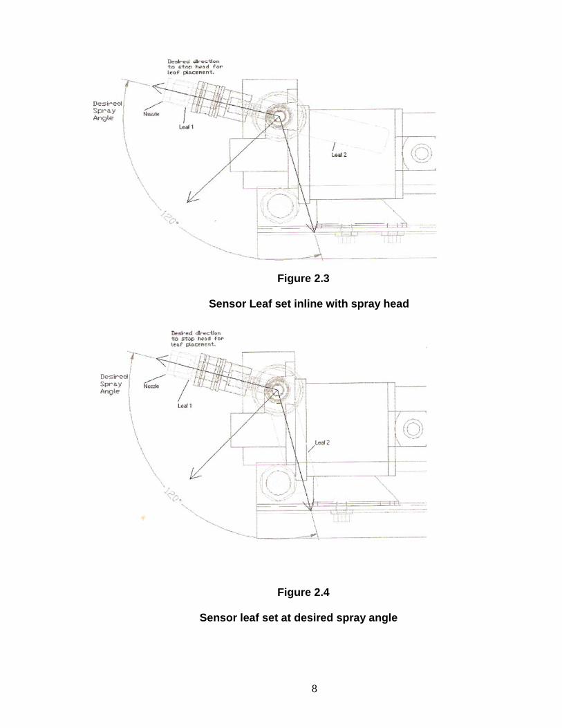
2.1.8.1 Set one of the leaves so that it lies along the nozzle. See
Figure 2.3
2.1.8.2 Set the second leaf to the desired spray angle. See Figure
2.4
2.1.8.3 Verify that the proximity sensor lies between the two
leaves in the direction of the spray. See Figure 2.5 and
Figure 2.5 A.
2.1.8.4 If needed, repeat the above steps until the leaves, nozzle
and the proximity sensor are all in the correct positions.
8
Figure 2.3
Sensor Leaf set inline with spray head
Figure 2.4
Sensor leaf set at desired spray angle

9
Figure 2.5
Proximity sensor between the two leaves
Figure 2.5A
Proximity Sensor Between the two leaves

10
Figure 2.6 Spray Head Sensor Leaves
2.1.9 If desired, one of the preset spray angle leaves may be used.
The set up procedure is the same except the angle will be
Predetermined.
2.1.10. Move the spray head switch to the on position and ensure
that the spray head nozzles oscillates in the correct angle.
2.1.11. Once verified, move the spray head switch to the OFF
position. 2.1.12. Move the Main Switch to the OFF Position. This is a general procedure for setting the spray angle of the device. This Procedure is designed to give you the basic set up operation of the spray.
Head. Depending on the desired direction of spray the nozzle may not be Inline with one of the sensor leaves.

11
2.2. Spray Head Height and Rotation Diameter:
2.2.1 Referring to the preparation for set up, recall any obstacles that
would impede the motion of the spray head or the rotational arm.
2.2.2 Determine the appropriate spray height and rotation diameter to
avoid any and all obstacles.
2.2.3 Support the spray head with one hand.
2.2.4 Remove the ball detent pin closest to the spray head from the
center plate. See Figure 2.7. It is necessary to depress the blue
button on the end of the pin to release the locking ball at the end
of the pin.
2.2.5 Rotate the head until the desired height is reached. The pin
must now be inserted back into the center plate. Once again, the
blue button must be depressed to release the locking ball at the
end of the pin.
2.2.6 Still supporting the spray head, remove the other pin ( closest to
the center rotation point) and adjust the final height of the spray
head.
2.2.7 It may be necessary to repeat the previous two steps until the
final position is reached.

12
Figure 2.7 Center Plate
2.3. Rotation Angle of the arm:
2.3.1 Determine the angle of rotation of the arm. See Figure 2.8.
2.3.2 Loosen the Wing nuts on the sense arm base plate. See Figure
2.9.
2.3.3 Rotate the sensor plates so that the desired angle is reached
NOTE: This will be opposite the desired angle. See Figure 2.10.
2.3.4 Verify the proximity sensor falls between the two leaves
opposite the desired angle. See Figure 2.11 and 2.11 A.

13
Figure 2.8 Desired Rotation Angle
Figure 2.9 Rotational Base

14
Figure 2.10 Sensor Tab Set opposite the desired spray angle.
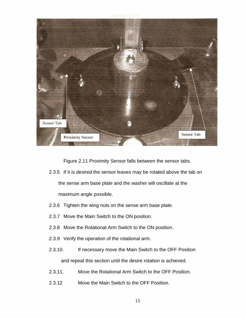
Figure 2.11 Proximity Sensor falls between the sensor tabs.
15
Figure 2.11 Proximity Sensor falls between the sensor tabs.
2.3.5 If it is desired the sensor leaves may be rotated above the tab on
the sense arm base plate and the washer will oscillate at the
maximum angle possible.
2.3.6 Tighten the wing nuts on the sense arm base plate.
2.3.7 Move the Main Switch to the ON position.
2.3.8 Move the Rotational Arm Switch to the ON position.
2.3.9 Verify the operation of the rotational arm.
2.3.10. If necessary move the Main Switch to the OFF Position
and repeat this section until the desire rotation is achieved.
2.3.11. Move the Rotational Arm Switch to the OFF Position.
2.3.12 Move the Main Switch to the OFF Position.

16
2.4 Reel Speed
2.4.1 First time set up.
2.4.1.1. Test the washer in you application for the appropriate
speed.
2.4.1.2 Locate the speed control Dial. It is located on the inside
of the cabinet to the right as you face the rear of the washer.
2.4.1.3. The dial is incremented form 0 to 10 in increments of 1.
2.4.1.4 A setting of 10 on the washer will move the washer
forward at 2.38 feet per minute with all the hose unreeled and
at 4.18 feet per minute with almost all the hose on the reel
The nominal, or average speed, is 3.6 feet per minute.
2.4.1.5. With the washer set up, position the dial to the desired
number.
2.4.1.6 Move the Main Switch to the ON position.
2.4.1.7 Move the Reel Motor Switch to the ON position.
2.4.1.8. Monitor the forward movement of the washer.
2.4.1.9. Adjust the dial setting until the desired speed is reached.
2.4.1.10 Move the Main Switch to the OFF position.
2.4.1.11 Move the Reel Motor Switch to the OFF position.
2.4.1.12. Push down the belt release lever until it stays in the down
position.
2.4.1.13. Move the washer back to the start point.
2.4.1.14. Move the belt release lever to the up, or activated
position.

17
2.4.2. Normal operation
2.4.2.1 Set the appropriate speed on the dial.
3. Operation of the Washer.
3.1 Move Main Switch to the OFF position.
3.2 Move Spray Head, Rotational Arm and Reel Motor Switches to the
ON position.
3.3. Close the rear door.
3.3.1. Ensure the closure handles are engaged to prevent the door
from swinging open during operation.
3.4 Perform a quick visual inspection of the area to ensure all obstacles
to the movement of the arm and spray head are removed or the
washer is set to avoid them i.e. hanging pipes and electrical lines
from the ceiling.
3.5 Move the Main Switch to the ON position.
3.6 Move to the water supply point.
3.7 Move to the water supply point.
3.8 Activate the valve or switch to supply water to the washer.
3.9 Verify the washer operates correctly.
3.10 First time users or first use in an area:
3.10.1. Monitor the washer to ensure no obstacles appear and the
washer moves along the appropriate path.

18
3.10.2. Monitor the arm swing and spray head operation to
ensure the proper operation.
3.11 In Normal operation, check the washer occasionally to ensure it is
operating correctly.
4. End of Operation:
4.1 The washer is factory set to continue operation of the arm and
spray head for ten minutes after arrival to the end point to complete
the cleaning cycle, this can be interrupted by moving the main switch
to the OFF position.
NOTE: TURN OFF THE WATER SUPPLY BEFORE APPROACHING THE WASHER. SERIOUS INJURY CAN OCCUR FROM THE HIGH PRESSURE WATER JET. 4.2 Allow the washer to complete the cycle.
4.3 Turn off the water supply.
4.4 Disconnect the hose from the water supply line.
4.5 Move the main switch to the OFF Position.
4.6 Disconnect the hose/cable grip from the anchor device.
4.7 Remove the anchor device and store,
4.8 Slide the hose/cable grip to the end of the hose.
4.9 Slide the hose ball and end sense plate to the end of the hose.
4.10 Depress the belt release lever.
4.11 Reel in the rest of the hose.
4.12 Support the Spray head.
19
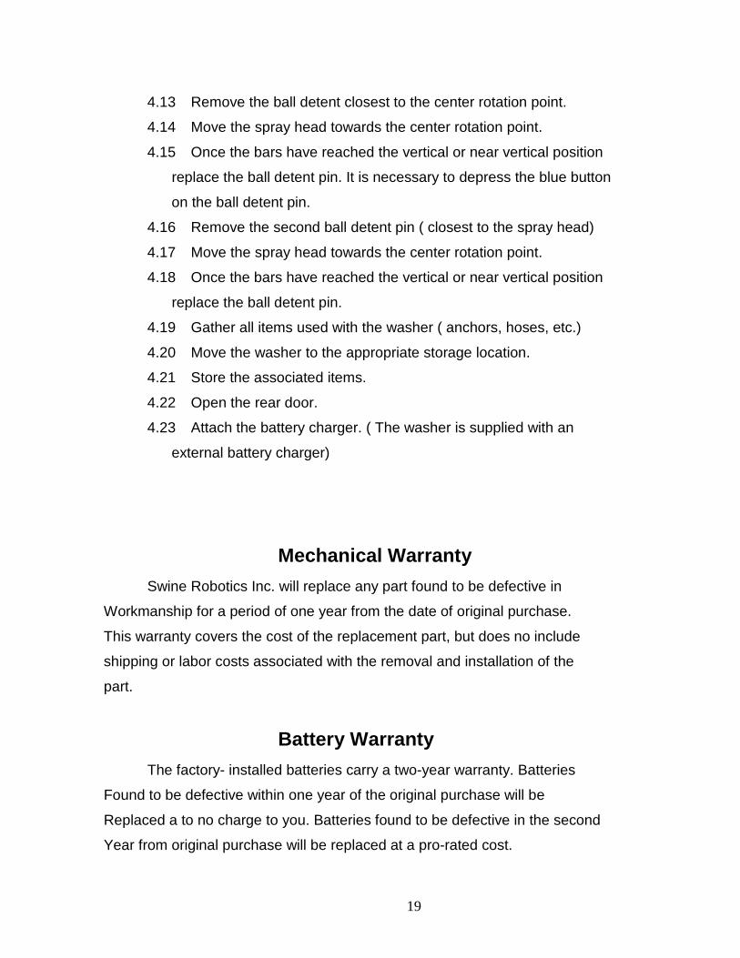
4.13 Remove the ball detent closest to the center rotation point.
4.14 Move the spray head towards the center rotation point.
4.15 Once the bars have reached the vertical or near vertical position
replace the ball detent pin. It is necessary to depress the blue button
on the ball detent pin.
4.16 Remove the second ball detent pin ( closest to the spray head)
4.17 Move the spray head towards the center rotation point.
4.18 Once the bars have reached the vertical or near vertical position
replace the ball detent pin.
4.19 Gather all items used with the washer ( anchors, hoses, etc.)
4.20 Move the washer to the appropriate storage location.
4.21 Store the associated items.
4.22 Open the rear door.
4.23 Attach the battery charger. ( The washer is supplied with an
external battery charger)
Mechanical Warranty Swine Robotics Inc. will replace any part found to be defective in
Workmanship for a period of one year from the date of original purchase.
This warranty covers the cost of the replacement part, but does no include
shipping or labor costs associated with the removal and installation of the
part.
Battery Warranty The factory- installed batteries carry a two-year warranty. Batteries
Found to be defective within one year of the original purchase will be
Replaced a to no charge to you. Batteries found to be defective in the second
Year from original purchase will be replaced at a pro-rated cost.

20
DO NOT RETURN BATTEIES UNDER WARRANTY TO SWINE ROBOTICS: CONTACT THE NEAREST EXIDE BATTERY DEALER WITH BATTERY WARRANTY ISSUES.
Service and Parts For parts an technical support contact:
Swine Robotics Inc. (605) 439-3510
Please promptly return warranty parts to the following address:
Swine Robotics Inc. 10858 365th Ave Leola, SD 57456

21
Parts List Part Number Nomenclature 525H-AH-ASM-01 Fuse Holder TM 100 27 Hairpin Cotter Pin
BB-525H –AC -01 Battery TM 100 34 Reduction Fitting 3/8
To ¼”
TM SA 100-03 Arbor base sub assembly TM 100 35 Quick Fit Disconnect
TM SA 100-06 Electronics Enclosure Sub
Assembly TM 100 36 Nozzle 04
TM 100 1 Base SST TM 100 36 Nozzle 06
TM 100 2 Side TM 100 36 Nozzle 08
TM 100 3 Top TM 100 36 Nozzle Adapter
TM 100 4 4 Bar Linkage Upper Arm TM 100 37 Reel Base
TM 100 5 4 Bar Linkage Center TM 100 38 Reel Motor
TM 100 6 4 bar linkage End TM 100 39 Reel
TM 100 7 Rotational Base Center post TM 100 40 Rigid Wheel
TM 100 8 Rotational Base Plate TM 100 41 Brass Bushing
TM 100 9 Rotational Base Support TM 100 42 Thrust Bearing
TM 100 10 Sleeve TM 100 43 Small Motor
TM 100 11 Upper Motor Base Plate TM 100 44 Swivel Wheel
TM 100 12 Upper Motor Prox Sensor
Arm TM 100 45 Venturi Rotational
Hose Attachment
TM 100 13 Motor Bracket TM 100 46 Thrust Washer
TM 100 14 Motor Bracket Adapter TM 100 47 Rotational Assembly
Belt (32” OD )
TM 100 15 Sleeve Top TM 100 48 Reel Pulley
TM 100 16 Front Guide TM 100 49 Reel Belt ( 75” OD )
TM 100 17 Right Arm Guide TM 100 54 Hose Stop
TM 100 18 Left Arm Guide TM 100 55 F to F SST 90 Fitting
TM 100 19 4 Bar Linkage Lower Arm TM 100 57 Upper Connection Hose
TM 100 20 Taper Bearing TM 100 58 Battery Locator
TM 100 20 Rotational Arm Pulley TM 100 59 Battery Tie Down
TM 100 21 Reel Motor Pulley/Rotational
Assembly Motor Pulley TM 100 60 All Thread Rod Rotational
Arm Sensor Base
TM 100 24 Rotational Base O Ring
#27 TM 100 62 Base
TM 100 26 Clevis Pin TM 100 63 Rotational Arm Position
Sensor

22
TM 100 66 Shaft Couple TM 100 105 Hose Quick Disconnect
TM 100 67 FF sst 90 Fitting TM 100 108 Grease Zerk
TM 100 69 MM SST Fitting .375 TM 100 112 Long Tie OFF
TM 100 70 PLC TM 100 113 1” Gap Tie OFF Base
TM 100 73 Switch TM 100 114 1” Gap Tie OFF Top
TM 100 74 DC Variable
Speed Controller
TM 100 115 3/8” Gap Tie OFF Base
TM 100 75 ½ F to 3/8 M TM 100 116 3/8” Gap Tie OFF Leaf
handle
TM 100 76 SST Hinge TM 100 117 3/8” Gap Tie Off Leaf Stop
TM 100 78 Battery Charger TM 100 123 120 Degree Spray Limitor
TM 100 79 Ball Detent Pin TM 100 124 105 Degree Spray Limitor
TM 100 80 Pressure Gauge TM 100 125 135 Degree Spray Limitor
TM 100 81 Pressure Gauge tee TM 100 126 150 Degree Spray Limitor
TM 100 82 Bushing ½ to 3/8 TM 100 128 Handle
TM 100 83 Bushing 3/8’to 1/4 TM 100 129 Small Down Rod
TM 100 84 Circuit Relay TM 100 130 Long Down Rod
TM 100 85 MM Close Nipple
¼”
TM 100 131 Reel Guard Cover
TM 100 87 Front Plastic TM 100 133 Switch Enclosure
TM 100 92 Rot Arm Rear Guard TM 100 134 M M Close Nipple ½”
TM 100 92 Rot Arm Front Guard TM 100 135 Cable Grip
TM 100 94 Rear Door TM 100 136 Potentiometer
TM 100 95 Reel Guard TM 100 137 Dial for Potentiometer
TM 100 96 Reel Guard Bracket TM 100 138 Wheel Brake
TM 100 97 Hose End Sense
Plate
TM 100 139 Proximity Sensor ¾”
TM 100 98 Rotational Motor TM 100 140 Flexible conduit Upper
TM 100 100 Proximity Sensor 1# TM 100 141 Flexible conduit Lower
TM 100 101 Rotational Base O
Ring #28
TM 100 142 U-Bolt ( Tie OFF)
TM 100 102 T Handle Closure TM 100 143 Switch Box
TM 100 104 Hose TM 100 143 Rot Motor Splash guard

23
TM 143 Rot Motor Splash Guard
TM 144 Lever Arm TM 145 Push Arm TM 146 Lever Pivot TM 147 Bushing Reel TM 148 Clamp Reel TM 149 Foam Tape TM 150 Pipe hanger TM 151 Water tight conduit
Adaptors TM 152 Tensioner TM 153 Tensior Shaft TM 154 Idler Pulley TM 155 Fuse 1 Amp TM 156 Fuse 3 Amp
TM 100-01 Base
TM 100-04 Upper Arm And TM 100-19 Lower Arm ( Lower has Two holes on one end)
TM 100-01 Base
Right TM 100-07 Center Post Bottom TM 100-08 Rotational Base Plate
TM 100-02 Side and TM 100-03 Top
TM 100-05 4 Bar Center
TM 100-06 See Picture TM 100-11

24
Left TM 100-10 Sleeve Right TM 100-15 Sleeve Top
Left TM 100-11 Upper Motor Base plate Right TM 100-06 4 Bar End
TM 100-12 Upper Arm Prox Sensor Arm/ Leaf
TM 100-13 Motor Bracket
TM 100-14 Motor Bracket Adapter TM 100-15 See TM 100-10
TM 100-21 Motor Pulleys
TM 100-16 Front Guide TM 100-17 Right Guide Arm 100-18 Left Guide Arm TM 100-19 See TM 100-04
TM 100-20 Rotational Arm Pulley with taper bearing
TM 100-26 Clevis Pin TM 100-27 Hairpin Cotter Pin Left TM 100-34 Reduction Fitting
3/8” to ¼” Right TM 100-75 Reduction Fitting ½” to 3/8”

25
*Left TM 100-24 Quick Fit Disconnect Nozzle *Middle Tm100-105 Quick Fit Disconnect Hose *Right Tm 100-80 Pressure Gauge
TM 100-37 Reel Base *TM 100-36 Nozzle *Left Nozzle Adapter *Middle Left 04 Nozzle *Middle Right 06 Nozzle *Right 08 Nozzle
TM-100-38 Reel Motor TM 100-39 Reel TM 100-40 Ridge Wheel
Left TM 100-41 Brash Bushing Right TM 100-137 Dial for Potentiometer
TM 100-43 Spray Head Motor ( small motor)
TM 100-42 Thrust Bearing TM 100-46 Thrust Washer
TM 100-44 Swivel Wheel TM 100-46 Thrust Washer See TM 100-42
TM 100-47 Rotational Belt
Right TM 100-45 Venturi Rotational Hose Attachment Left TM 100-42 Pressure Gauge tee

26
TM 100-48 Reel Pulley before cut
TM 100-49 Reel Belt TM 100-54 Hose Stop
Left TM 100-55 F to F 90 ½” Right TM 100-67 F to F 90 3/8”
TM100-57 Upper Connection Hose
TM 100-58 Battery Locator
TM 100-59 Battery Locator
TM 100-60 All Thread Rod
Left TM 100-62 Rotational Arm Sensor Base Right Tm 100-63 Rotational Arm Position Sensor or Sensor tab TM 100-67 See Tm 100-55
TM 100-66 Shaft Couple TM -69 3\8” Close Nipple Alternate
TM 100-70PLC
TM 100-73 Switch TM 100-75 See TM 100-34 TM 100-78 Battery Charger
TM 100-74 Variable Speed Controller

27
TM 100-76 SST Hinge
TM 100-85 ¼” Close Nipple
*Left TM 100-82 Bushing ½ *Middle TM 100-83 Bushing 3/8” *Right TM 100-69 M to M Fitting3/8”
TM 100-79 Ball Detent Pin
TM 100-84 Circuit Relay TM 100-87 Front Plastic TM 100-92 Rear Gear
TM 100-94 Rear Door
TM 100-97 Hose end Senses Plate
TM-100-93 Front Guard
TM 100-96 Reel Guar Bracket TM 100-95 Reel Guard
TM 100-98 Rotational Motor
TM 100-102 Closure Handle
TM 100-101 Rotational Base O Ring
TM 100-100 Proximity Sensor ¾”
TM 100-104 Hose
TM100-105 see TM 100-35

28
TM 100-112 Long Tie off TM 100-113 1” Gap Tie off Base TM 100-115 3/8” Gap Tie Off Base TM 100-117 3/8” Gap Tie off leaf Stop TM 100-124 105 Spray Limitor TM 100-126 150 Spray Limitor TM 100-129 Small Down Rod TM 100-131 Reel Guard Cover TM 100-114 1” Tie Off Top TM-116 3/8” Gap Tie Off Leaf Handle TM 100-123 120 Spray Limitor TM 100-125 135 Spray Limitor TM 100-128 Handle TM 100-130 Long Down Rod TM 100-134 MM Close ½” Nipple TM 100-137 see TM 100-41
TM 100-134 MM Close 1/2” Nipple TM 100-108 Grease Zurk
TM 100-135 Cable Grip
TM 100-136 Potentiometer TM 100-138 Wheel Brake
TM 100-139 Proximity

29
TM 100-140 And TM 100-141 TM 100-145 Push Arm TM 100-144 Lever Arm TM 100-143 Rotational Motor Splash Guard
TM 100-147 Bushing Reel TM 100-149 Foam Tape TM 100-148 Clamp Reel
TM SA 100-03 Arbor Base Sub Assembly
TM 100-150 Pipe Hanger TM 100-SA 100-06 Electronics Enclosure
TM 100-155 1 Amp Fuse TM 100-156 3 Amp Fuse TM 100-152 Tensioner
TM 100-153 Tensioner Shaft TM 100-154 Idler Pulley
TM 100-151 Water Tight Connectors
TM 100-160 Switch Box

30
Maintenance Monthly Maintenance The Wash Hand has been designed to give you many hours of trouble free service with minimal maintenance. To help extend the life of you machine and keep it operating smoothly the following maintenance should be performed. 1. Lubrication
1. All Lubrication can be accomplished with a standard grease gun.
1.1 Wheels 1.1.1 Grease the rigid rear wheels.
1.1.1.1 The zurk is located on the outside of the wheel at the hub.
1.1.2 Grease the swivel Wheels
1.1.2.1 A grease zurk is located on the outside of the wheel at the hub.
1.1.2.2 A second grease zurk is located at the base of the wheel
(the base will be defined as where the wheel attaches to the washer).
CAUTION: Do not tilt or turn the washer over with the batteries inside.
This could cause damage to the washer the surroundings or could cause serious injury.
1.2. Idler
1.2.1 A grease zurk is located on the end of the idler shaft facing the inside
of the washer.
1.3 Rotational Arm
1.3.1 A grease zurk is located on the top of the rotational sleeve.

31
2 Check battery water level
CAUTION: Avoid skin or clothing contact with battery acid. If contact occurs,
Flush with water immediately!
2.1 It will be necessary to remove one of the batteries to perform this service.
2.2 Verify that all switches are in OFF position.
2.3 Remove the positive and negative wires from the right battery.
2.4 Remove the nylon insert lock not on the all thread rod to the right
of the batteries.
2.5 Lift the end battery hold down and rotate out of the way.
2.6 Check the right battery.
2.6.1 Lift and remove the right battery out of the washer.
2.6.2 Carefully pry the caps off and check the water level.
2.6.3 If the battery cells are not full, fill using only distilled water.
2.6.4 Firmly push battery caps back into position.
2.7 Check the left battery.
2.7.1 Slide the battery to the right so that access to the battery is not
hindered.
2.7.2 Carefully pry the caps off and check the water level.
2.7.3 If the battery cells are not full, fill using only distilled water.
2.7.4 Firmly push battery caps back into position.
2.8 Reinstall the batteries.
2.8.1 Slide the left battery back to its original position.
2.8.2 Replace the right battery.

32
2.8.3 Rotate the battery hold down back into position.
2.8.4 Place the battery hold down over the all thread rod.
2.8.5 Replace the nylon insert lock nut.
2.8.6 Reattach the negative and positive wires to the appropriate
terminals on the right battery.
3. Cleaning battery connections.
3.1 Check to see that the power switch is in the “OFF” position.
3.2 Remove the terminal connections from the batteries.
3.3 Remove any corrosion from the battery terminals using emery
Cloth or fine sandpaper.
3.4 Reconnect wire terminals and apply anti-grease or spray.
4 Check Belt Tension
4.1 Rotational Arm Belt
4.2 Remove Front Guard
4.3 Remove the four 10-24 Pan Head Phillips Screws and the 10-24
Nylon inset lock nuts.
4.4 Lift and move the guard off to the side. Do not damage the
proximity sensor wires.
4.5 Check the belt tension.
4.6 Adjust the tension if necessary.
4.6.1 Loosen the ¼”-20 Hex Head Bolts on the Rotational Motor
bracket.
4.6.2 Move the motor in or out as needed to correctly tension the belt.

33
4.6.3 Tighten the ¼”-20 Hex Head Bolts.
4.7 Place the front guard back into position taking care not to bind the proximity sensor
wires under the guard or fouling the wires on the belt.
4.8 Replace the four 10-24 Pan Head Phillips Screws and the 10-24 Nylon insert lock
nuts
5 Reel Belt Tension.
5.1 The tensioning device should automatically apply tension. If tension
is not present or correct, contact the service department.
Yearly Maintenance
1 Move the Main Switch to the OFF Position.
2 Remove the negative lead form the left battery.
3 Belt replacement
4 Replace the reel belt
4.1 Remove the reel guard. 4.1.1 Remove the ¼-20 Hex head bolt from the reel guard and reel guard bracket. 4.1.2 Remove the ¼-20 nylon inset hex nuts from the inside of the reel guard.
4.1.3 Remove the inside panel of the reel guard.
4.1.4 Remove the 10-24 Pan Head Phillips screws from the reel
guard.
4.1.5 Remove the reel guard.
4.1.6 Move the belt release lever to the down position.

34
4.17 Remove one of the screws from the front plastic guide.
4.1.8 Rotate the front plastic guide 90 the front.
4.1.9 Remove the hose from the guide.
4.1.10 Reel the hose onto the reel
4.2 Remove the belt from the drive pulley.
4.2.2 Remove the belt from the peel pulley.
4.2.3 The belt must be removed from the washer by passing it completely
over the reel.
4.3 Replace the belt
4.3.1 Place the belt onto the reel pulley
4.3.2 Place the belt onto the drive pulley
4.4 Replace the reel guard
4.4.1 Unreel a portion of the hose.
4.4.2 Place the hose into the guide.
4.4.3 Rotate the plastic guide back into the original position.
4.4.4 Replace the removed screw in the plastic guide.
4.4.5 Move the belt release lever to the up position.
4.4.6 Replace the reel guard.
4.4.7 Replace the 10-24 Pan Head Screws.
4.4.8 Replace the inside panel of the reel guard.
4.4.9 Replace the 1/2-20 nylon hex nuts.
4.4.10 Replace the ¼-20 Hex Head bolt on the reel guard and
reel guard bracket.
35
5 Replace the Rotational Arm Belt
5.1 Remove the front guard.
5.1.1 Remove the 10-24 Pan Head Phillips screws
5.1.2 Remove the plastic nut from the top of the proximity sensor.
5.1.3 Remove the proximity sensor from the guard.
5.1.4 Place the guard to the side
5.2 Remove the rear guard
5.2.1 Remove the 10-24 Pan Head Phillips Screws.
5.2.2 Slide the rear guard to the rear and place to the side.
5.3 Remove the Rotational head Assembly.
5.3.1 Supporting the arms and spray head.
5.3.2 Remove the hairpin cotter pins from the clevis pins on the
rotational sleeve.
5.3.3 Remove the clevis pins.
5.3.4 Lay the Rotational Head assembly to the side
5.4 Remove the Rotational motor splashguard.
5.4.1 Remove the 10-24 Pan Head Phillips screws.
5.4.2 Lay the splashguard to the side,
5.5 Loosen the ½-40 Hex Head bolts on the rotational head motor
bracket.
5.6 Slide the motor towards the rotational sleeve.
5.7 Remove the belt.
5.7.1 Remove the belt from the motor pulley
5.7.2 Remove the belt from the rotational assembly pulley.

36
5.8 Replace the belt.
5.8.1 Place the belt on the rotational assembly pulley.
5.8.2 Place the belt on the motor pulley.
5.9 Slide the motor away from the rotational assembly until proper belt
tension is achieved.
5.10 Tighten the ¼-20 Hex Head Bolts.
5.11 Replace the Rotational motor splashguard.
5.11.1 Place the splashguard into its original position.
5.12 Replace the arms and spray head assembly.
5.12.1 Place the arms and spray head assembly into its original position.
5.12.2 Replace the clevis pins.
5.13.3 Replace the hairpin cotter pins.
5.13 Replace the rear guard.
5.13.1 Place the rear guard into its original position.
5.13.2 Replace the 10-24 Pan Head Phillips screws.
5.14 Replace the front guard
5.14.1 Place the proximity sensor into the front guard.
5.14.2 Replace the proximity sensor plastic nut.
5.14.3 Place the front guard into its original position.
5.14.3.1 Ensure not to pinch the proximity sensor wires under
the guard or bind the wires in the belt.
5.14.4 Replace the 10-24 Pan Head Phillips screws.
6 Replace the negative wire on the negative terminal of the battery.

37
Trouble Shooting
This section is for general trouble shooting of the washer. It is not intended to
be a comprehensive guide to repair.
1 Reel does no turn:
Possible Cause Possible Solution
Proximity sensor on front of washer is activated Hose ball is up against sensor, move
hose ball away
Remove any steel object from in front of
sensor
(approximately ½” sense range)
Main Switch not completely tripped Cycle switch to OFF and then ON
Reel Motor Switch no Completely tripped Cycle switch to OFF and then ON
Low voltage condition Check voltage, should be 24 volts.
Charge or replace batteries as necessary.
Belt is loose Move the belt release lever to the up
position.
Verify the tensioning arm is operating
(located inside the cabinet).

38
Reel brake is engaged On the reel under the reel guard, there is
a spring loaded pin with a ring attached.
Verify; that the pin is in not engaged. If
engaged, pull ring and rotate
approximately 90 ,there is a slot that will
engage the ring.
Motor does not turn Contact customer support
2 Arm does not turn
Proximity sensor on front of washer is activated. Hose ball is up against sensor, move
hose ball away.
Remove any steel objects from in front
of sensor ( approximately1/2”)
Proximity sensor on front guard is activated. Move sensor plates
Main Switch not completely tripped Cycle switch to OFF and then ON
Rotational Arm Switch not completely tripped Cycle switch to OFF and then ON
Belt is loose Verify belt tension (see Maintenance
section) tighten as necessary.
The arm is obstructed Remove obstructions
Low voltage conditions Check voltage, should be 24 Volts
charge.
Or replace batteries as necessary
Motor does not turn Contact customer support

39
3 Spray Head does not turn
Proximity sensor on front of washer is activated Hose ball is up against sensor, move
hose ball away
Remove any steel objects from in front
of sensor ( approximately1/2”)
Proximity sensor is activated Move sensor leaves Main Switch not completely tripped Cycle switch to OFF and then ON Rotational Arm Switch not completely tripped Cycle switch to OFF and then ON Spray head is obstructed Remove obstructions Low Voltage condition Check voltage, should be 24 volts.
Charge or replace batteries as necessary
Motor does not turn Contact customer support 4 Rotational Arm turns beyond sensor plate tabs Proximity Sensor inoperable Verify operation, main switch on,
rotational arm switch on, place a steel
object over sensor, look for light on
bottom (rear) of sensor, it may be
necessary to remove the front guard.
Low voltage in batteries Check voltage, should be 24 volts.
Charge or replace batteries as necessary
5. Spray head turns beyond sensor leaves Proximity sensor inoperable Verify operation, main switch on, spray
head switch on, place a steel object over
sensor, look for light on bottom (rear)
of sensor.
Sensor leaves are beyond the sense range Move leaves closer to proximity sensor

40
6 Reel does not stop Proximity sensor inoperable Verify operation, main switch on , reel
motor switch on, place a steel object
over sensor, look for light on bottom
(rear) of sensor
Switch engagement incorrect Cycle all switches 7 Rotational Arm does not stop Switch engagement incorrect Cycle all switches
Low voltage condition Check voltage, should be 24 volts.
Charge or replace batteries as necessary
Proximity sensor inoperable Verify operation, main switch on, reel motor switch on, place a steel object over sensor, look for light on bottom
(rear) of sensor
8 Spray head does not stop Switch engagement incorrect Cycle all switches
Low voltage condition Check voltage, should be 24 volts.
Charge or replace batteries as necessary
Proximity Sensor inoperable Verify operation, main switch on, reel
motor switch on, place a steel object
over sensor, look for light on bottom
(rear) of sensor
41
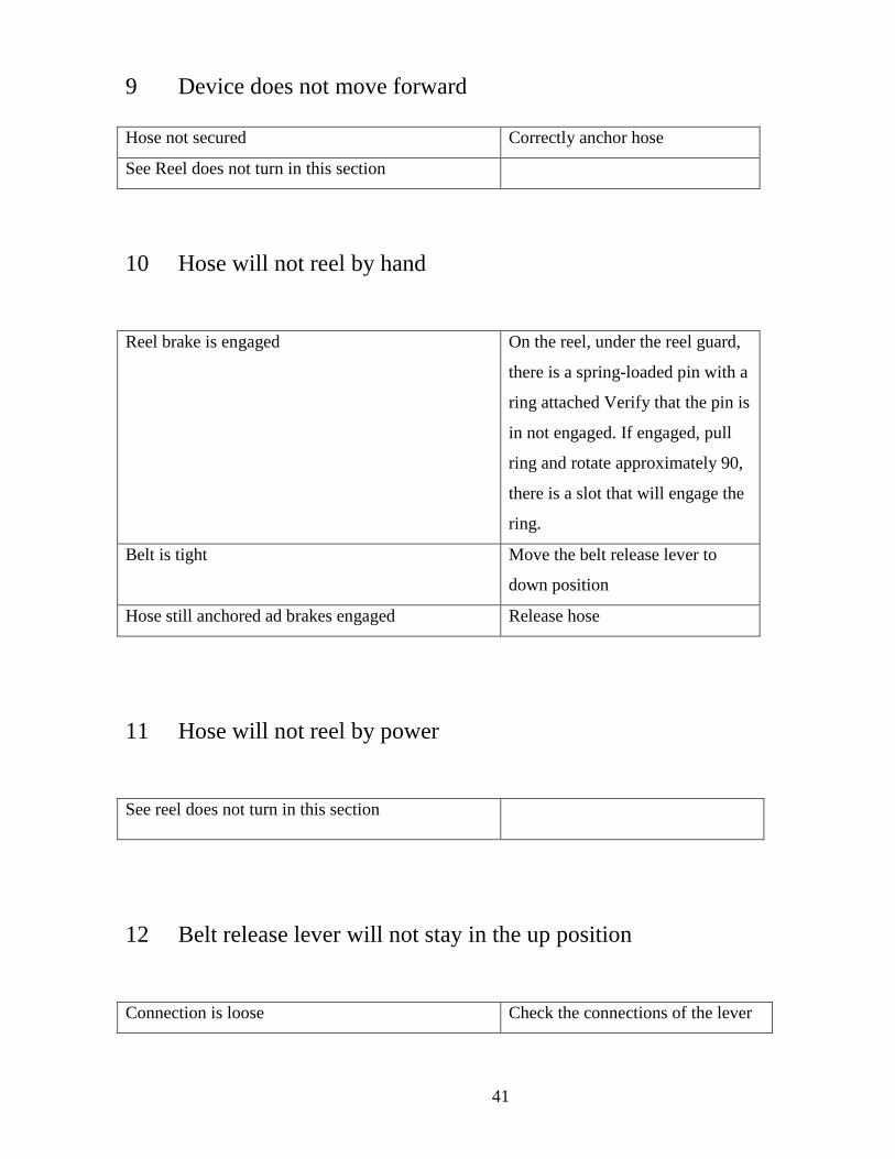
9 Device does not move forward Hose not secured Correctly anchor hose
See Reel does not turn in this section
10 Hose will not reel by hand
Reel brake is engaged On the reel, under the reel guard,
there is a spring-loaded pin with a
ring attached Verify that the pin is
in not engaged. If engaged, pull
ring and rotate approximately 90,
there is a slot that will engage the
ring.
Belt is tight Move the belt release lever to
down position
Hose still anchored ad brakes engaged Release hose
11 Hose will not reel by power
See reel does not turn in this section
12 Belt release lever will not stay in the up position
Connection is loose Check the connections of the lever

42
Tighten or reconnect if needed
Tensioning arm is inoperable Replace tensioning device
13 Belt Release lever will not stay in the down position
Connection is loose Check the connections of the lever.
Tighten or reconnect if needed
Tensioning arm is inoperable Replace tensioning device
14 Wheels will not roll
Rear wheel brake engaged Release brake
Wheels are obstructed Remove obstruction
Bushings are corroded Clean or replace as necessary
15 Wheels will not swivel
Wheels are obstructed Remove obstructions
Bearing are corroded Clean or replace as necessary
16 Water does not flow Water supply valve is closed Open supply valve
Pump is not operating Turn on pump or repair pump
Nozzle is clogged Turn on pump or repair pump
Obstruction in hose or fixture Remove and clean
17 Sprays in the wrong direction

43
Refer to spray head set up in the operation section
of this manual
18 Batteries do not charge or maintain charge Low battery water lever Check water lever as outlined in
the “monthly maintenance”
Section
Corroded battery connections Clean connections as outlined in
the “monthly maintenance” section
Battery Charger not correctly attached to batteries Verify charger connections at the
batteries
Faulty battery charger Check that battery charger is
working replace as necessary
Faulty batteries Have battery condition checked at
local battery dealer. Replace as
necessary
Service
1 Replacing spray head motor.
1.1 Disconnect the negative battery cable from the rear of the
batteries. ( See Figure Service 1.1)
1.2 Remove the arbor base assembly.
1.2.1 Loosen the Allen Hex set screw. (See Figure Service 1.2)
1.2.2 Slide assembly off of motor shaft
1.3 remove the Nozzle Assembly
1.3.1 Loosen the Allen Hex set screw in the shaft couple.

44
( See Figure Service 1.2)
1.3.2 Slide the Assembly off of the motor shaft
Figure Service 1.1 Battery connections
1.4 Disconnect the motor from the electrical system. The Motor
is equipped with a quick fit coupling.
1.5 Remove the four ¼”-20 hex head bolts.
1.6 Remove the motor
1.7 To place the new motor, accomplish the above steps in
reverse.

45
Figure Service 1.2 Spray Head
Figure Service 1.2A Spray Head

46
2 Replacing the Rotational Arm Motor.
2.1 Disconnect the negative battery cable from the rear or the
batteries. ( see Figure Service 1.1)
2.2 Remove the rotational motor splashguard. ( see Figure
service 2.1)
2.2.1 Remove the two # 10-24 Pan head Phillips screws.
2.2.2 Remove the splashguard.
2.3 Remove the front guard. ( see Figure Service 2.1)
2.3.1 Remove the four # 10-24 pan head Phillips screws.
2.3.2 Lift and move the front guard to the side, careful
not to damage the proximity sensor wires.
Figure Service 2.1 Rotational Arm Motor Replacement

47
Figure Service 2.3 Rotational Motor Service
3 Replacing the Reel Motor.
3.1 Disconnect the negative battery cable from the rear
of the batteries. ( see Figure Service 1.1)
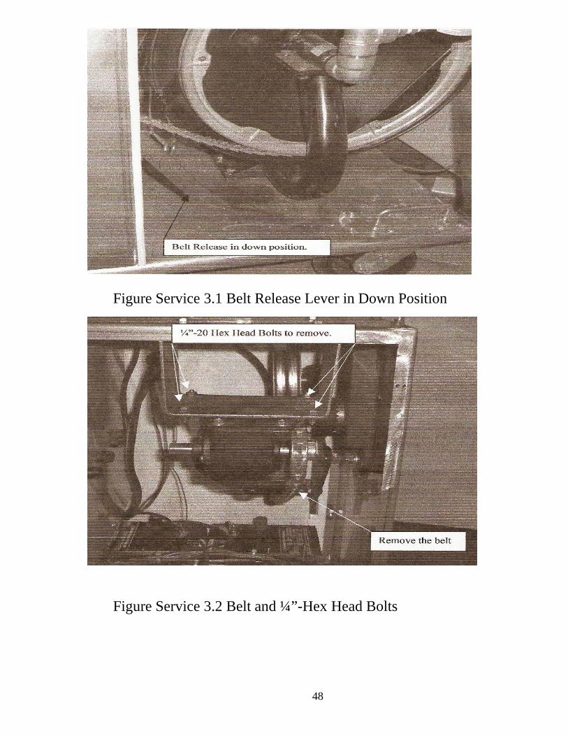
3.2 Move the belt release lever to the down position.
( see Figure Service 3.1)
3.3 Remove the belt from the motor pulley. (see Figure Service 3.2)
3.4 Remove the four ¼”-20 hex head bolts. (see Figure service 3.2)
3.5 Lay the motor down behind the washer.
3.6 Open the electrical box.
3.6.1 There are eight screws in the electrical box cover
48
Figure Service 3.1 Belt Release Lever in Down Position
Figure Service 3.2 Belt and ¼”-Hex Head Bolts

49
3.6.2 Locate the variable speed controller. (Upper right in the
electrical box, ( see Figure Service 3.3)
Figure Service 3.3 Electrical Box
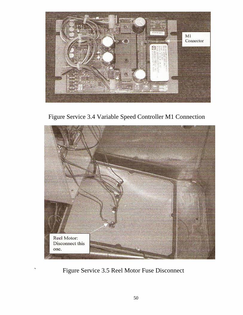
3.7 Remove the wire attached to the M1 connector on the Controller.
(see Figure Service 3.4)
3.8 Remove the wire attached to the reel motor fuse (the wire will be
one wire that goes to the motor, (see Figure Service 3.5).
3.9 Loosen the water tight connector that the motor leads go through.
3.10 Remove the moor leads from the box.
3.11 Replace the motor using the above steps in reverse order. Ensuring
that the motor leads are attached with the brown wire to the M1
Block and the blue wire to the fuse holder.
50
Figure Service 3.4 Variable Speed Controller M1 Connection
` Figure Service 3.5 Reel Motor Fuse Disconnect

51
4 Replace a Bushing or Bearing in Rotational Arm
4.1 Disconnect the negative battery cable from the rear
of the batteries ( see Figure Service 1.1).
4.2 Remove the Rotational Arm.
4.2.1 Remove the Hairpin Cotter Pins.
4.2.2 Remove the Clevis Pins.
4.2.3 Lay rotational arm to the side.
Figure Service 4.1 Clevis and Cotter Pins
4.3 Remove front and rear guards.
4.3.1 Remove the eight # 10-24 Pan Head Phillips Screws.
4.3.2 Slide rear guard to rear and set aside.
4.3.3 Lift and set front guard to the side (careful not to
damage the proximity sensor wires).

52
Figure Service 4.2 Front and Rear Guard
4.4 Remove the rotational arm belt from the pulley (it may be
necessary to loosen the belt to remove ( refer to replace rotational
arm motor).
4.5 Lift off rotational center Assembly to expose the Bushings and
Bearings.
4.6 replace Bearings, Bushings or O Rings as needed.
4.7 perform these steps in reverse order to return washer to original
configuration.

53
Figure Service 4.3 Rotational Center Assembly
Figure Service 4.4 Bushing, Bearings and o Rings.

54
Wire Diagram
This wiring diagram is included for the possible use in troubleshooting
the washer. At no time should an attempt be made to rewire the washer.

55
Swine Robotics Inc.
10858 365th Ave
Leola, SD 57456
(605) 439-3510 Shop
(605) 439-5312 Fax
WashHand Spec
The WashHand Is:
1 As Semi. Automated washer designed to dispense high
pressure water.
2 Rated for 3000 PSI Maximum working pressure
3 24 volt power systems (2-12 volt batteries)
4 One Year warranty on parts
5 Weight 340LBS
6 Dimension 32” L 18”W 41”H
7 Operated By 3-24 Volt Motor
8 Stainless Steel

56


![swine flu kbk-1.ppt [Read-Only]ocw.usu.ac.id/.../1110000141-tropical-medicine/tmd175_slide_swine_… · MAP of H1 N1 Swine Flu. Swine Influenza (Flu) Swine Influenza (swine flu) is](https://img.dokumen.tips/doc/110x75/5f5a2f7aee204b1010391ac9/swine-flu-kbk-1ppt-read-onlyocwusuacid1110000141-tropical-medicinetmd175slideswine.jpg)