Embed Size (px)
Citation preview
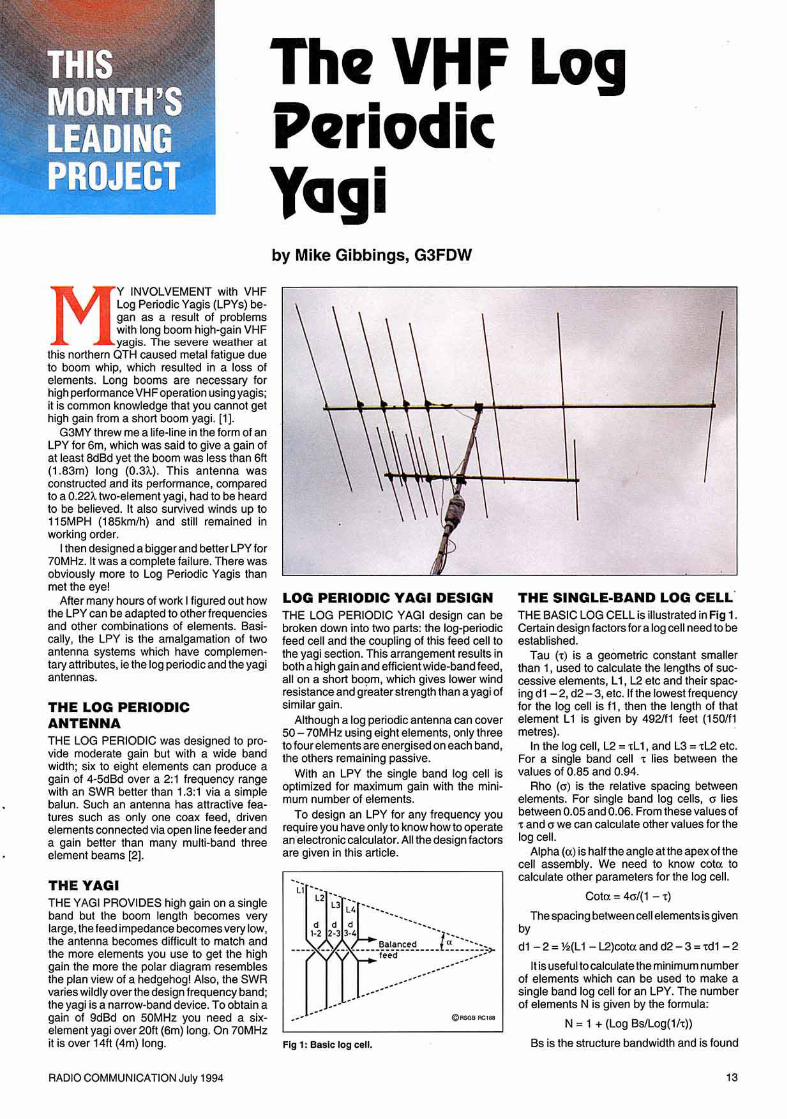
The VttFLogPeriodicVagiby Mike Gibbings, G3FDW
My INVOLVEMENT with VHFLog PeriodicYagis (LPYs) began as a result of problemswith long boom high-gainVHFyagi::;. TI le severe weather at
this northern QTH caused metal fatigue due10 boom whip, which resulted in a loss ofelements. Long booms are necessary forhighperformanceVHFoperation usingyagis;it is common know ledge thai you cannot gethigh gain Irom a short boom yagi. [1).
G3MYthrew me a life-line in the formof anLPY for 6m, which was said 10 give a gain ofat least 8dBd yet the boom was less than 6ft(1.83m ) long (O.3J..). This antenna wasconstructed and its performance, comparedto a 0.2n two -element yagi, had 10be heardto be believed. II also survived winds up 10115MPH (185km/h) and still remained inworking orde r.
I then des igned a bigger and better LPY for70MHz. It was a complete failu re. There wasobvio usly more to Log Periodic Yagis thanmet the eye !
After many hours of work I figu red out howthe LPY can be adapted to other frequenciesand othe r combinations of eleme nts . Basicall y, the LPY is the amalgamation of twoantenna systems which have complementary attributes, ie the log periodic and the yag iantennas.
THE LOG PERIODICANTENNATHE lOG PER IODIC was des igned to provide moderate gain but with a wide bandwidth ; six to eight elements can produce again of 4-5dBd over a 2:1 frequency rangewith an SWR better than 1.3:1 via a simplebalun. Such an antenna has att ract ive features such as only one coax feed, drivenelements connec ted via open line feeder anda gain better than many multi-band threeelement beams [2].
THE VAGITHE YAGI PROVI DES high gain on a singleband but the boom length becomes verylarge , the feed impedance becomes very low,the antenna becomes difficult to match andthe more elements you use to get the highgain the more the pola r diagram resemblesthe plan view of a hedgehog ! Also, the SWRvaries wildly over the des ign frequency band ;the yag i is a narrow-band device. To obtain again of 9dBd on 50MHz you need a sixelement yagi over 20ft (6m) long . On 70MHzit is ove r 14ft (4m ) long .
RADIO COMMUNICATION July 1994
LOG PERIODIC VAGI DESIGNTHE LOG PERIODIC YAGI design can bebroken down into two parts: the log-periodicfeed cel l and the coupl ing of this feed call tothe yagi sec tion . This arrangement results inboth a high gain and efficient wide-band feed ,all on a short boo m, which gives lower windresistance and greate r strength than a yagi ofsim ilar gain.
Although a log periodic antenna can cover50 - 70MHz using eight elements , only threeto four elements are energised on each band ,the others remaining passive.
With an LPY the single band log cell isoptimized for max imum gain with the minimum number of elements.
To design an LPY for any frequency yourequi re yo u have only to know howto ope ratean elect ronic calculator. All the design factorsare given in this art icle.
Fig 1; BasIc log cell.
THE SINGLE·BAND LOG CELL·THE BAS IC LOG CEll is illustrated in Fig 1.Certain des ign factors for a log cell need to beestablished .
Tau (.) is a geometric constant smallerthan 1, used to calculate the lengths of suc cessive elements , l l , L2 etc and their spacing d 1-2,d2-3, etc. If the lowest frequencyfor the log cell is f l , then the length of thatelement 11 is given by 4921f1 feet (1501f1metres).
In the log cell, L2 =.L1, and L3 ", . L2 etc.For a single band cell 't lies between thevalues of 0.85 and 0.94 .
Rho (a) is the relat ive spacing betweenelements. For sing le band log cells, a liesbetwee n 0.05 and 0.06. From these values of• and a we can calcu late othe r values for thelog cell.
Alpha (a) is half the angle at the apex of thece ll assembly . We need to know cote tocalculate other parame ters fo r the log cell.
cote = 40" (1 - . )
The spacing between cell elements is givenby
d1 -2 = ~(11 - tzjcotc and d2-3= rd t -2
It is useful to calculate the minimum numberof elements which can be used to make asingle band log cell for an LPY. The numberof elements N is given by the formula;
N = 1 + (l og BsIlog(lh))
Bs is the struc ture bandwidth and is found
13
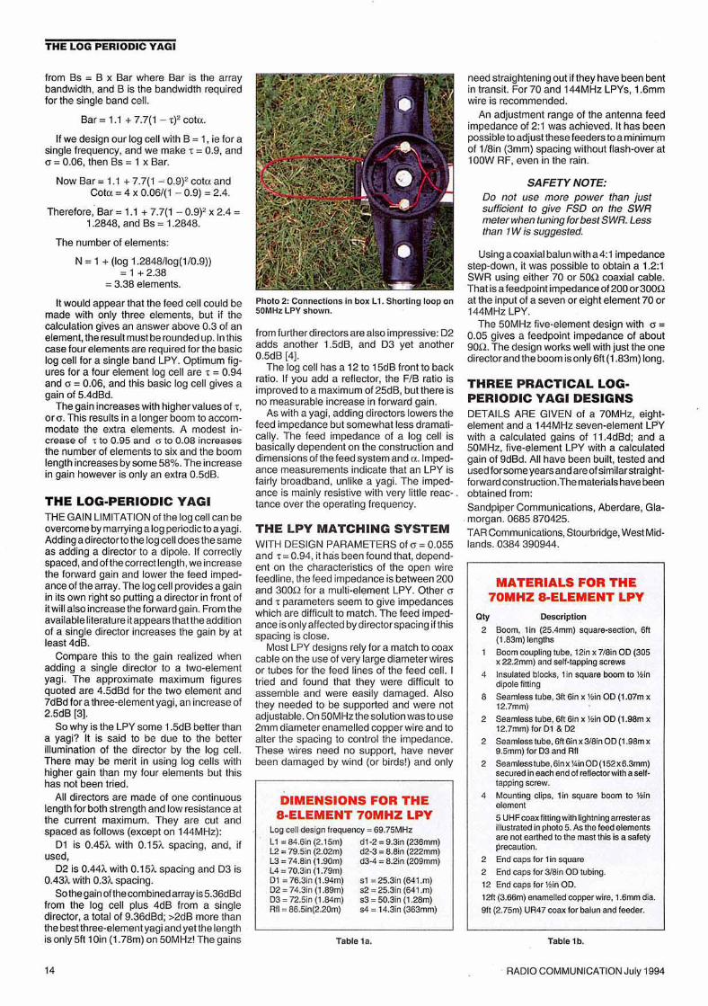
Table t e.
sr = 25.3;n (641.m)52 = 25.3in (64l .m)sa'" 50.3in (1.28m)s4 = t4.3in (363mm)
THE LOG PERIODIC YAG I
from Bs '" B x Bar where Bar is the arraybandwidth, and B is the bandwidth requiredfor the single band cell .
Bar = 1.1 + 7.7(1 - 't"f cote .
If we design our log cell with B = 1, ie for asingle frequency, and we make r = 0.9, and0 = 0.06. then Bs = 1 x Bar.
Now Bar = 1.1 + 7.7(1 ~ 0.9)2cot« andCote '" 4 x 0.06/(1 - 0.9) = 2.4.
Therefore: Bar = 1.1 + 7.7(1 - 0.9)2x 2.4 '"1.2848, and Bs = 1.2848.
The number of elements:
N = 1 + (log 1.2848 /log(1/0.9))= 1+ 2.38
'" 3.38 elements.
It would appear that the feed cell could bemade with only three elements, but if thecalculation gives an answer above 0.3 of anelement , the result must be rounded up. In thiscase four elements are required for the basiclog cell for a single band LPY. Optimum figures lor a four element log cell are t '" 0.94and (J = 0.06, and this basic log cell gives again 01 5.4dBd.
The gain increases with higher values of t ,or o . This results in a longer boom to accommodate the extra elements. A modest increase of 't to 0.95 and G to 0.08 increasesthe numbe r of elements to six and the boomlength increases by some 58% .The increasein gain however is only an exira O.5dB.
THE LOG-PERIODIC YA GITHE GAIN LIMITATION of the log cell can beovercomebymarrying a log periodic 10 a yagi.Adding a orrector to the log cell does the sameas adding a director to a dipole. If correctlyspaced,and of the correct length,weincreasethe forward gain and lower the feed impedance of the array. The log cell provides a gainin its own right so pUlling a director in front ofitwill also increase the forward gain. From theavailable literature itappears that the additionof a single director increases the gain by atleast 4dB.
Compare this to the gain realized whenadding a single director to a two-elementyagi. The approxim ate maximum figuresquoted are 4.5dBd for the two element and7dBd for a three-eleme nt yag i, an increase of2.5dB 13].
So why is the LPY some 1.5dB beller thana yagi? It is said to be due to the bellerillumination of the director by the log cell.There may be merit in using log cells withhigher gain than my four elements but thishas not been tried.
All directors are made of one continuouslength for both strength and low resistance atthe current maximum. The y are cut andspaced as follows (except on 144MHz):
Dl is 0.45t.. wllh 0.15t.. spacing, and, ifused,
D2 is 0.44t.. with 0.15"- spacing and D3 is0.43"- with 0.3A. spacing .
Sothegain ofthecombinedarray is 5.36dBdfrom the log cell plus 4dB from a singledirector , a total of 9.36dBd ; >2dB more thanthe best three-element yagiand yet the lengthis only 5tt tOin (1.78m) on 50MHz! The gains
14
Pholo 2: Connections In box L t . Shorl ing loop on5UMHz LPY shown.
from further directors arealso impressive: D2adds another 1.5dB, and D3 yet another0.5dB [4].
The log cell has a 12 to 15dB front to backratio. If you add a reflector, the FIB ratio isimproved to a maximum of 25dB, but there isno measurable increase in forward gain.
As witha yagi , adding directors lowers thefeed impedance but somewhat less oramatlcally. The feed impedance of a log cell isbasically dependent on the construction anddimensions of the feed system and n.tmpedance measurements indicate that an LPY isfairly broadband, unlike a yagi. The impedance is mainly resistive with very lilli e reac- .tance over the operating frequency.
THE LPY M ATCH ING SY STEMWITH DESIGN PARAMETERS of a = 0.055and r '" 0.94. it has been found that , depend ent on the characte ristics of the open wireteeonne. the feed impedance is between 200and 300n for a multi-element LPY. Other IJ
and r parameters seem to give impedanceswhich are difficult to match. The feed impedance is only affected by director spacing if thisspacing is close .
Most LPY designs rely for a match to coaxcable on the use of very large diameter wiresor tubes for the feed lines of the feed cell. Itried and found that they were difficult toassemble and were easily damaged. Alsothey needed to be supported and were notadjustable.On 50MHz the solution was touse2mm diameter enamelled copper wire and toalter the spacing to control the impedance.These wires need no support, have neverbeen damaged by wind (or birds!) and only
DIMENSIONS FOR THEa-ELEMENT 70MHZ LPY
Logcell design frequency '" 69.75MHz11 '" 84.6in (2.l 5m) er-a'" 9.3in (236mm)L2= 7g.5in (2.02m) d2-3 '" aso (222mm)L3= 74.81n (1.90m) d3·4 '" 8.2in (209mm)L4 =70.3in (1.79m)0 1 '" 76.3in (t. 94m)02 ", 74.3in (t. 89m)03 ", 72.5in (t. 84m)Rn'" 86.5in{2.20m)
need straightening out if they have been bentin transit. For 70 and 144MHz LPYs, 1.6mmwire is recommended.
An adjustment range of the antenna feedimped ance of 2:1 was achieved It has beenpossible to adjust these feeders to aminimumof 1/8in (3mm) spacing without flash-over attOOW RF, even in the rain.
SAFETY NOTE:Do not use more power than justsufficient to give FSD on the SWRmeier when luning for best SWR.Lessthan 1W is suggested.
Using a coaxialbalunwitha 4:1impedancestep-down, it was poss ible to obtain a 1.2:1SWR using either 70 or 50n coaxial cable.That is a feedpoint impedance ctzco or 300nat the input of a seven or eight element 70 or144MHz LPY.
The 50MHz live-element design with IJ =0.05 gives a feedpoint impedance of about9012. The des ign works well with just the onedirectorand the boom is only 6ft (1.83m) rong.
THREE PRACTICAL LOGPERIODIC YA GI DESIGNSDETAilS ARE GIVEN of a 70MHz, eightelemen t and a 144MHz seven-element LP'Ywith a calculated gains of 11.4dBd; and a50MHz, five-e lement LPY with a calculatedgain of 9dBd. All have been built , tested andused for some years and areofsimilarst raight·forwardconstruction.Thematerialshave beenobtained from:Sandpiper Communicat ions, Aberdare , Glamorgan . 0685 870425.TAR Communications,Stourbridge,West Midlands. 0384 390944.
MATERIALS FOR THE70MHZ a-ELEMENT LPY
QIy Desc riptl on
2 Boom. tin (25.4mm) square-section. 611(t .83m) lenglhs
800m coupling tube, 12in l( 7/6in 00 (305l( 22.2mm) and self·lapping screws
4 Insulatfl'd blocks, tin square boom 10 l!> indipolefimng
6 Seamless lube. 3116in x l!>in 00 (1.07m xl2.7mm)
2 Seamless lube, 611 6in x l!>in 00 (1.96m xl 2.7mm) for 0 1 & 02
2 Seamless luDe. 6lt6inx318in 00 (l .98m x9_5mm) for 03 and RII
2 SeamlessluDe,6in l( 'liin OO(IS2l(6.3mm)secured in each end of eeuectcrwnnasaillapping screw.
4 Mounling clips. l in square boom 10 Y.linelement5 UHFcoaxlining wilh lightningarrester asulusrrated in photo 5. As mefeed erenentsare nol eannee 10 the mast this is a safetYprecaution.
2 End caps lor t in square
2 End caps for 318in00 lubing.
ta End caps lor Y.lin 00.
t 2ft (3.66m) enamelled copper wire, t.emm dia.
911(2.75m) UR47 ccexfor balun and feeder.
Table 1b.
RADIOCOMMUNICATIONJuly 1994
THE LOG PERIODIC VAGI
•
Balanc~d
I~~d to
101le..11
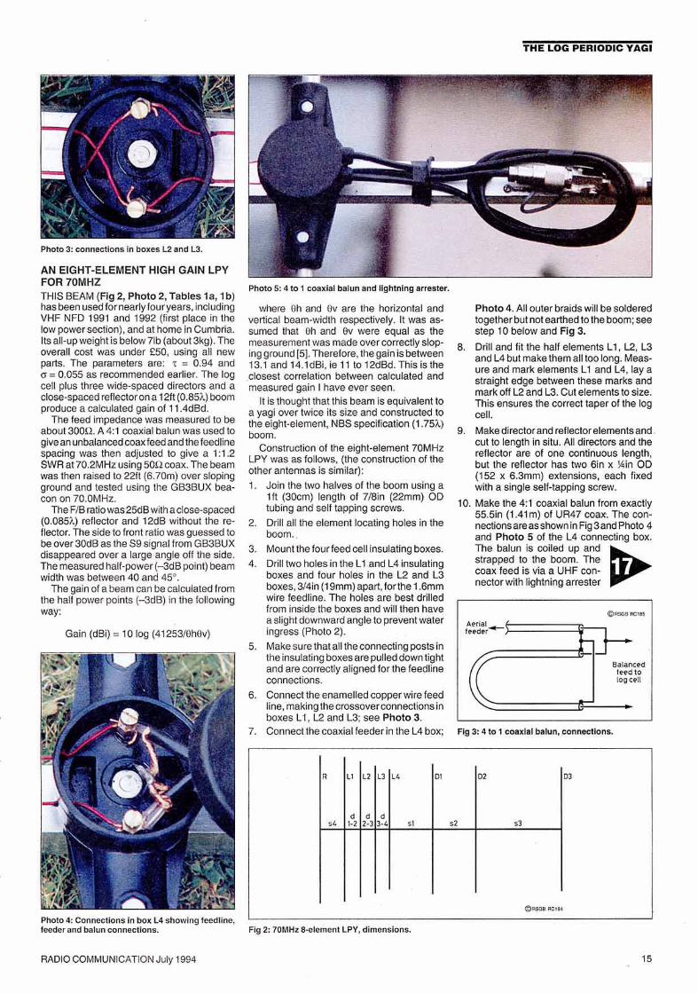
Photo 4. All outer braids will be solde redtcqetherbut not earthed to the boom; seestep 10 below and Fig 3.
8. Drill and fit the half elements L1, L2, L3and L4 but make Ihem all too long. Measure and mark elements L1 and L4, lay astraight edge between these marks andmark off L2 and L3. Cut elements to size.This ensures the correct taper of the logcel l.
9. Make direc tor and reflector elemen ts and .cut to length in situ. All directors and thereflector are of one continuous length,but the reflector has two 6in x lAin 00(152 x e.amm j extensions, each fixedwith a single self-tapping screw.
10. Make the 4:1 coax ial balun from exactly55.5in (1.41m) of UA47 coax-. The connections areas shown in Fig 3 and Photo 4and Photo 5 of the L4 connecting box.The balun is coiled up and~strapped to the boom. Thecoax feed is via a UHF con-nector with lightning arrester
Fig 3: 4 to 1 coax ial balun, connecti on s.
where Oh and uv are the horizontal andvert ical beam-width respectively. It was assumed that Oh and av were equal as themeasurement was made over correctly sloping ground 15]. Therefore . the gain is between13.1 and 14.1dBi, fe 11 to 12dBd . This is theclosest correlation between calculated andmeasured gain I have ever seen .
It is thought that this beam is equiva lent toa yagl over twice its size and cons tructed tothe eight-element, NBSspecilication (1.751..)boom.
Construction of the eight -element 70MHzLPY was as follows, (the construction of theother antennas is sim ilar):
1. Join the two halves of the boom using a1ft (30cm) length of 7/8in (22mm) 00tubing and self tapp ing screws.
2. Drill all the element locating holes in theboom . .
3. Mount the four feed cell insulating boxes .
4. Drill two holes in the L1 and L4 insu latingboxes and four holes in the L2 and L3boxes, 3/4in (19mm) apart, forthe 1.6mmwire feedline . The holes are best drilledlrom inside the boxes and wm then havea slight downward angle to prevent wateringress (Photo 2).
5. Make sure thatall the conn ect ing posts inthe insula ting boxes are pulled down tightand are cor rectly aligned for the teeonneconnections.
6. Connect the enamelled copper wire feedline, making the crossover connections inboxes L1, L2 and L3; see Photo 3.
7. Connect the coaxial feede r in the L4 box;
Photo 5: 4 to 1 coax ial balun and ligh tn ing arrester.
, t .t cz ra " or " oa
, , ," ,., a-a ,., st vr "
(Q"OllB~ '"
AN EIGHT·ELEMENT HIGH GAIN LPYFO R 70MHZTHIS BEAM (Fig 2, Photo 2, Tables t a, 1b)has been used for near ly four years, includingVHF NFO 1991 and 1992 (first place in thelow power sect ion), and at home in Cumbria.Its all-up weight is below 71b (about 3kg). Theoverall cost was under £50, using all newparts. The parameters are: ,= 0.94 ando = 0.055 as recommended earlie r. The logcell plus three wide-spaced directors and aclose-spaced reflector on a 12ft (0.85i.)boomproduce a calc ulated gain of 11.4dBd.
The feed impedance was measured to beabout auoa. A 4:1 coaxial balun was used togive anunbalanced coax feed and the reeonnespacing was then adjusted to give a 1:1.2SWA at70.2MHz using son coax. The beamwas then raised to 22ft (6.70m) over slopingground and tested using the GB3BUX beacon on 70.0MHz.
The FIB ratio was 25dB with a close-spaced(0.085;'.) reflector and 12dB without the reflector . The side to front ratio was guessed tobe over 30dB as the S9 signal from GB3BUXdisappeared over a large angle olf the side.The measured half-power (-3dB point) beamwidth was betwe en 40 and 450
•
The gain of a beam can be calculated fromthe half power points (-3dB) in the followingway:
Photo 4: Connec tio ns In box L4 show ing leedllne.leeder and balu n co nnections. Fig 2: 70MHz a-element LPY, dimensions.
Gain (dBi) = 10 log (41253/UhUv)
AAOIOCOMMUNICATION July 1994 15

THE LOG PER IODIC VAGI
Photo 6: 50MHlr 5-element LPY.
Photo 7: Clole up of 144MHlr log eenteeenoe.
DIMENSIONS FOR THE 50MHZ LPY FIG 4
reere a
MATERIALS FOR THEf44MHZ 7-ELEMENT LPY
Qty DH crlptlon1 Boom. 511 (l.52m) ~ l in OO lul:Hng. Donot
substitute a square boom.3 ope-n1in boom to 3113in dipole fillinga
1 oonr.aeting box, l in boom to 3f8in dipol&fill ing
3 lin boom to 3I8jn ele mounVngclamps
I 3tt enamelledcower wire. l .6mmdla1 27in (686mm) (exaetlength)UR47ooa~ 'or
balun.
Al lelementa:3'8 in(9.5mm)OOaaamless lubing
Table3b.
col 2 L) l 4
" oz 03
st " "
,d d J·41-22·J e""",,,,,,,,
Fig 4: 50MHz Ilv_ lement LPY, dlmenalons.
Fig 5 : 144MHz eeven-etement LPY, dl menelona.
co " U " "'
, , ,,., a.a '"' "
4:)"""""","
0 1 . l 08.34n (2.75m)sl .. 35.51n (902mm)L4 .. 98.71n (2.51m)
TBble 3B.
L1 .. 41.9in (l064mm) d1-2 . 4.6in ( l 17mm)L2 .. 39.4In (1000rnm) d2-3 _ 4.34n (11Omm)L3.. 37.o;n (939mm) d3-4 . 4.1in (104mm)L4 . 34.7in (881mm)
0 1 • 35.9in (912mm) sl .. 7.3In (195mm)02 ", 35,3in (895mm) 52.. 10,OIn (254mm)D3.. 34.11n (II66mm) 53 . 29.5In (749mm)
DIMENSIONS FOR THE144MHZ LPY
ACKNOWLEDGMENTSTO DA G M KING, G3MY, for all his help andenco uragement and who inspired me to thinkthat there must be som ething better than aVagi. Also to Dr T H Wilmshurst , G3IBY, whogave me food lor thought with his contributionto Technical Topics (Aug 1990) on the acc urate measurement of ern beam gain.
was 141MHz to improve the FIB ratio to 15dBwithout the use of a reflector.
As on the 70MHz LPY, Ihe feed cell feederspacing was adjusted to give a SWR of 1.1:1at 144.3MHz. At 145.5MH z the SWR was1.5:1.
The connections to L1,12 and l3 from the1.6mm wire feeder are made using smallsolder tags attached to each element end byself tapping scre ws (Pho to 7). All connections are solde red in situ.
REFERENCES:[1] ARRLAnienna Book, 1988,Chap.l 1 Figs
20 and 21 (see Book case page s 94and 95).
[21ARRL Antenna Book, 1988, Chap.l0
[3] YagiAntennaDesign, (Dr James LLawson,W2PV), Chap 1, table 1.5
14J 'LPY Gai n' by Lea Johnson , Ham Radio,May 1983, pp78·82.
[51 'Moxon Slopes ' , Les Moxon, G6XN,RadCom , June 1988.
dl·2 " 12.Oin (305mm)d2·3 .. 11.34n (287mm)d3·4 _ 10.6in (270mm)
L1 .. 118.11n (3.llOm)l2 .. 1 1t.trn (2,82m)L3.. 104.&n (2,66m)
with its earth strap taken to a selftapping screw into the boom.
On completion spray inside eachdipole box with Finnigans Waxoyl
(obtainable from Hatlords) and refit lids .
16th Edition
Members' Price: £ 14.0 3
ARRL Antenna Book
THE 144 MHZ SEVEN· ELEMENT LP YTHE CALCULATED GAI N is 11.4dBd using1:= 0.94 and 0"'" 0.055 and the boom lengthis Sit (1.52m ). This beam was designed forthe low end of the 144MHz band. See Fig 5,Photo 6 and Tabl es ae, 3b .
The feed ce lt design frequency chosen
THE ORI GINAL SOMHZ FIVEELEMENT LPYTHE CALCULATED GAIN was 9.36dBd using1:= 0.94 andO"=O.05 . Total boom leng th wasunder ett (1.83m). See Fig 4 and Table 2 ,
This antenna has been used for ove r lou ryea rs both portable and at home. It stood upto very high winds and came through batteredbut in working order. I have worked all connnents on SOMHz with it.
The feed 10 the log cell uses a short leng thof thin 70U coa x wound in six turns on anRSGB ferrite core to form a cnoke balun.Th ecoax ends are connected to the feed cellterminals.
The original wasbuiltwitha 1in (25mm)ODround boom but a square boom, as in theeight-element 70MHz beam, could also beused. Construction forthe log cell ISas torme70MHz LPY. Use 70n coax feed er. To improve the FIB ratio L1 is fitted with a 7inshorting loop (see Photo 2) .
RADIO COMMUNICATION July 1994 17