Embed Size (px)
Citation preview
The very Best.
www.ppc insu l a tors .com
Only a company that develops,
produces and delivers products
worldwide can provide the optimal
solution for your requirements.
The specialists of PPC Insulators
are dedicated to supplying you with
superior advice and global support.
PPC Insulators quality products
and service provide time-tested
value to fulfill your needs!
Please visit us on the web at
www.ppcinsulators.com
That’s what we deliver.
Re
visi
on
1/
20
03
Railway Insulators
The very Best.

PPC Insulators, after more
than 70 years of experience
in designing and manufacturing
railway porcelain insulators,
has developed a new concept
to improve safety and
performance while optimizing
cost considerations for
our customers.
Our research, in conjunction
with national and transnational
railway companies, yielded
a high-grade design for
C130 porcelain material with
the optimum cement for
assembly and fittings.
Metallic hardware connections
can easily be designed using
high-grade material for fittings
according to customer specifications.
> IEC > DIN > ÖNORM Index
> DesignMechanical Design PAGE 4
Fittings PAGE 4
Glazing PAGE 5
Electrical Performance PAGE 5
Pollution Levels PAGE 6
K-value Design PAGE 7
Shed design PAGE 7
> Product FeaturesAssembling PAGE 8
Hardware PAGE 8
Tolerances PAGE 8
> ProductsPantograph Post PAGE 9
Overheadline Catenary PAGE 10
Post Catenary PAGE 12
Posts and Rods PAGE 13
> ControlOverhead Railway Insulators PAGE 14
Conversion table PAGE 15
Posts and Rods PAGE 15
Intr
od
uc
tio
nR
ailw
ay I
nsula
tors
Intr
od
uc
tio
nR
ailw
ay I
nsula
tors
Insulators for High Speed TrainSafe traveling
From the 1930’s into
the third millennium, we’re
reducing weight while offering
the highest performance.
Since the 1930’s, we have
manufactured insulators
for overhead lines supplying
railway networks. Originally,
system electrification voltage
was 1.5 to 3 kV D.C.
The need for speed from town
to town required improvements
in the electrification system,
thus 15 & 25kV AC voltages
were chosen to replace DC.
Railway porcelain insulators are
subjected to the most severe
service conditions, electrical
and mechanical stresses, due to
parameters of the service site
and their performance specifi-
cations as required by worldwide
railway companies.
Safe traveling at more than 300 km/h (190 mph)

In-service stresses for catenary insulators are mainly due to tension or bending loads
(e.g., tension and vibration in wires, feeder, wind pressure, ice, short circuit loads).
Few applications induce compression strength (depending on catenary mounting
arrangement) or torsion strength when using as rotating air disconnects.
Designing for H.S.T. (High Speed Train) needs to take into account high security
for railway lines. PPC experience in this field (more than 25 years), has led us to use
special high-grade material for the porcelain body with an appropriate shed design.
PPC Insulators manufacturing plants mainly use C130 body for this range
of insulators (catenary or post insulators) because of its high-grade high-quality properties.
This allows a smaller core diameter, smaller sized fittings and makes insulators lighter.
PAGE 5PAGE 4
Railway InsulatorsDesign
Mechanical Design
Material Flexural Flexural Modulus of Linear SpecificStrength Strength Elasticity thermal WeightUnglazed Glazed Expansion
Coefficient*
Mpa Mpa x 10 3 Mpa x 10 –6 K-1
psi psi psi
C120 body100 140 70
4.5 to 5.5 2.414500 20300 10150
C130 body165-180 190-200 100
4 to 6 2.723925-26100 27550-29000 14500
Material data according to IEC 60672Indicative mean values on test samples
* Temperature range from 20°C to 300°C
Electrical Performance
De
sig
nR
ailw
ay I
nsula
tors
De
sig
nR
ailw
ay I
nsula
tors
Creepage distance calculations
and performance have been
improved through our relationships
with our customers the world over.
Mechanical performance, too,
has been enhanced through the
rigors of speeding along at more than
300 km/hour (~190 mph.), requiring
excellent knowledge concerning the
electrical behavior of railway insulators
and their mounting arrangment on-site.
Pollution performance is one of
the most important points to consider
when designing a railway insulator.
Furthermore, we must take into
account the kind of pollution and
its severity according with pollution
class levels from IEC 60815.
Material for Fittings is usually malleable cast or
ductile iron. Protection against corrosion is made by
hot dip galvanizing according to IEC 60383-60168.
For galvanization, we recommend a minimum
nominal thickness of ≥ 85µm (or 3.3 mil).
PPC Insulators can design and provide High Grade
aluminium for fittings as an alternative for our
customers. Standard sizes for fittings for busbars
or air disconnect switches are used.
We can design fittings for Catenary Insulators
of any kind according to the standard live parts connection
for clamping based on customer usage.
Mechanical Data for Fittings
Standard indicative values
on test samples
Fittings
Glazing
Semi-conductive glaze (SCG) can be provided for special polluted environments.
We also have developed state-of-the-art shed design to optimize performance.
BrownGlaze
is according to
RAL 8017 & RAL 8016
GreyGlazeis according to
RAL 7038 or ANSI Z55.1. (MUNSELL 5BG7.0/0.4)
Grey glazed insulators provide an enhanced visual
aesthetic advantage and compliment the tone
of the metallic poles. These neutral colors blend well
with most environments in which it is situated.
For each application, PPC Insulators offers the best choice for the design by using “K-Value” method and for the quality surface (e.g. SCG).
Material Tensile Modulus of Linear SpecificStrength Elasticity Thermal Weight
ExpansionCoefficient
Mpa x 10 3 Mpa x 10 –6 K-1
psi psi psi
Malleable 350 23011 7.35
cast iron 50750 33350
Ductile 400 25011 7.2
cast iron 58000 36250
Aluminium250-290 210
21 2.7alloy casting36250-42050 30450
Al-Si-Mg

PAGE 6 PAGE 7
Pollution Levels
> Areas generally of moderate extent, subjected to conductive dusts and to industrial smoke producing particularly thick conductive deposits.
> Areas generally of moderate extent, very close to the coast and exposed to sea-spray or to very strong and polluting winds from the sea.
> Desert areas, characterized by no rain for long periods, expsed to strong winds carrying sand and salt, and subjected to regular condensation.
> Areas without industry and with low housing density equipped withheating plants.
> Areas with low density of industry or houses but subjected to frequent winds and/or rainfall.
> Agricultural areas.
> Mountainous areas.
> Industrial areas not producing particulate polluting smoke and/or with average housing density equipped with heating plants.
> Areas with high density of houses and/or industry but subjected to frequent winds and/or rainfall.
> Areas exposed to wind from the sea but not too close to the coast (at least several kilometers distant).
> Areas with high density of industries and suburbs of large cities with high density of heating plants producing pollution.
> Areas close to the sea in any case exposed to relatively strong winds from the sea.
Level Pollution Specific Creepage Distance1 Light 16 mm/kV 0.630 inch/kV
Level Pollution Specific Creepage Distance2 Medium 20 mm/kV 0.787 inch/kV
Level Pollution Specific Creepage Distance3 Heavy 25 mm/kV 0.984 inch/kV
Level Pollution Specific Creepage Distance4 Very Heavy 31 mm/kV 1.220 inch/kV
In its full extent, K-value design is a method to reduce
> weight > volume and > space
while improving properties in service by increasing
pollution performance and equalizing electrical f ield.
K-value Design Increased Pollution Performance Equalized Field Distribution
Form factor used as a design method
is referred to as K-value and can be used
for different improvements.
Creepage distance considers a leakage
current as traveling along the exterior
contour of the insulator, identifying only
the linear distance.
K-value considers a leakage current as traveling
along the insulator over its surface. K-value identifies
an insulator’s total shape, i.e., geometric (ohmic)
resistance against leakage currents. It is necessary
to calculate the shape of the surface of the insulator
for reaching optimum pollution performance. Distance Distance and Diameter
K-value design is
a method to improve
traditional creepage
distance.
PPC Insulators offer complete computer design of K-value, integrated with traditional requirements.
P
S IdC=d
S
P1P1
P2P2
Id2Id2
Id1Id1
d2d2
C=d1C=d1
S
P
Id
C=d
Shed designWe recommend the plain or
alternating sheds for general
uses because of their best
self-cleaning properties.
According to our research,
choosing an appropiate shape
for sheds is also important
for the optimum behavior
against impact .
Guidance on design and
selection of creepage distance
with respect to environmental
conditions can be found in
IEC recommendation 60815.
Basic levels of pollution are
qualitatively defined with
examples of typical environment
situations. Corresponding
minimum nominal creepage
distance is given in mm/kV.
International standard IEC 60507 defines form factor as:
F = ∫ dl/p(l)l is the creepage distance
p(l) is the circumference of the insulator as a function of l.D
es
ign
Railw
ay I
nsula
tors
De
sig
nR
ailw
ay I
nsula
tors
Railway InsulatorsDesign
Plain Shed Standard ShedAlternating Shed
Traditional calculation of creepage distance is
still used, but to achieve best performance in relation to
material and space used, K-value design is essential.
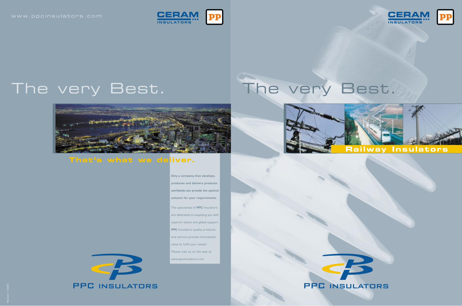
AssemblingPPC Insulators uses three kinds of assemblies
for fittings mated to the porcelain:
> Lead antimony alloy from -50°C to 150 °C
> Sulfur cement from -50°C to 80 °C
> Portland Cement base from -30°C to 105 °C
The environmental conditions and the use of insulators dictates
the choice of assembly. Temperature, specific mechanical strength,
and other parameters must be considered to make the right choice
for the best performance of the insulators.
PAGE 9PAGE 8
Hardware (when applicable)
PPC Insulators can deliver metallic hardware
after agreement with the railway utility.
Railway InsulatorsProduct Features
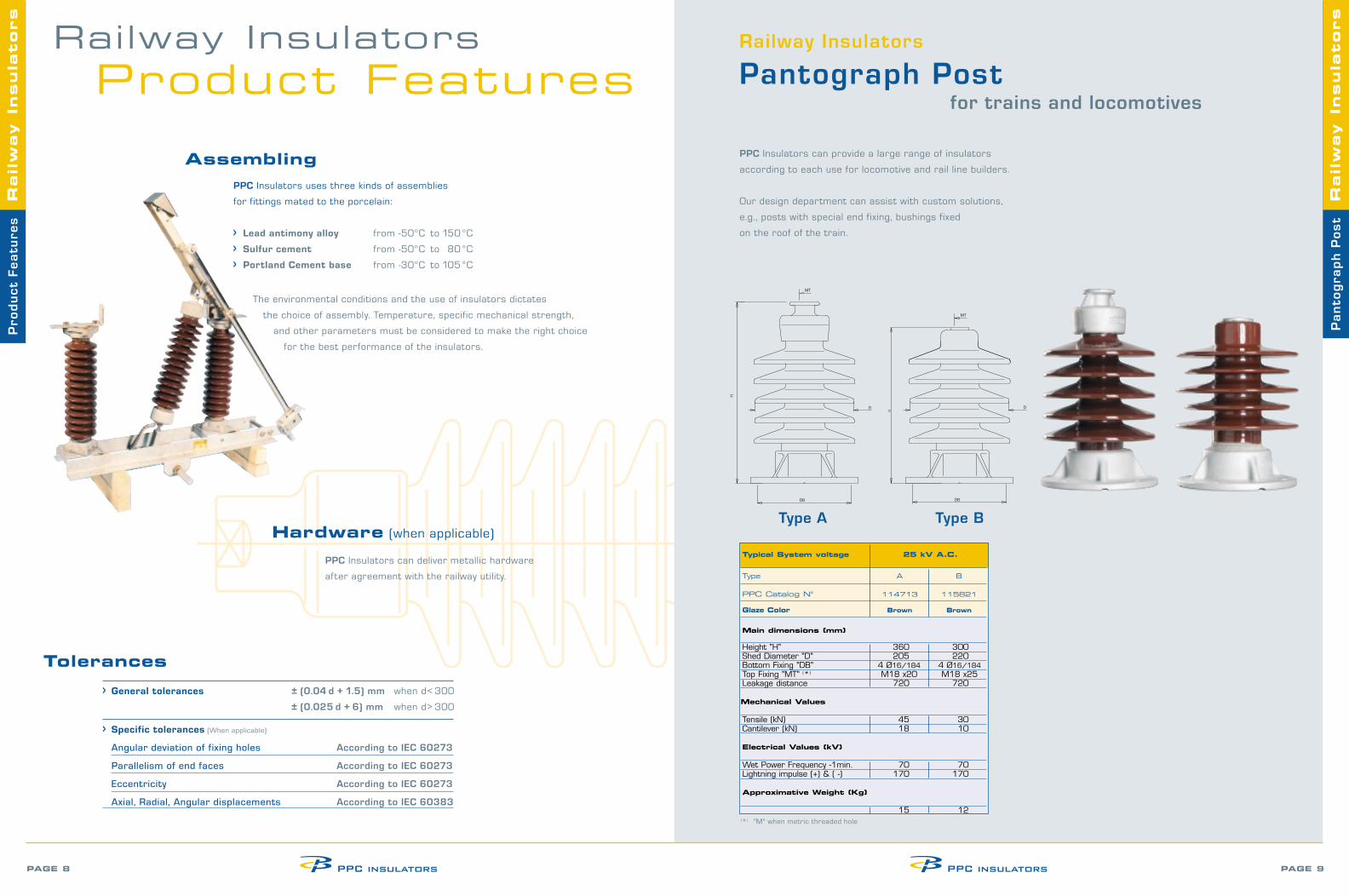
PPC Insulators can provide a large range of insulators
according to each use for locomotive and rail line builders.
Our design department can assist with custom solutions,
e.g., posts with special end fixing, bushings fixed
on the roof of the train.
Typical System voltage 25 kV A.C.
Type A B
PPC Catalog N° 114713 115821
Glaze Color Brown Brown
Main dimensions (mm)
Height "H" 360 300Shed Diameter "D" 205 220Bottom Fixing "DB" 4 Ø16/184 4 Ø16/184Top Fixing "MT" (*) M18 x20 M18 x25Leakage distance 720 720
Mechanical Values
Tensile (kN) 45 30Cantilever (kN) 18 10
Electrical Values (kV)
Wet Power Frequency -1min. 70 70Lightning impulse (+) & ( -) 170 170
Approximative Weight (Kg)
15 12(*) "M" when metric threaded hole
Pro
du
ct
Fe
atu
res
Railw
ay I
nsula
tors
Pa
nto
gra
ph
Po
st
Railw
ay I
nsula
tors
Railway Insulators
Pantograph Post for trains and locomotives
Tolerances
> General tolerances ± (0.04 d + 1.5) mm when d< 300
± (0.025 d + 6) mm when d> 300
> Specific tolerances (When applicable)
Angular deviation of fixing holes According to IEC 60273
Parallelism of end faces According to IEC 60273
Eccentricity According to IEC 60273
Axial, Radial, Angular displacements According to IEC 60383
Type A Type B

The single-piece core design for 3 kV DC or 25 kV AC
with special design provides maximum protection
after flashovers and against mechanical impact.
PPC Insulators designed for working
in the horizontal position or angle mounted
on a crossarm provides maximum safety
for the electrical line connection with the train.
We supply the entire range of insulators
for each voltage level:
1.5 – 3 kV DC
15 – 25 kV AC
PAGE 11PAGE 10
25 kV A.C. Overhead Line Catenary Insulators
Typical System voltage 25 kV A.C.
Type A A A* B B B* C D*
PPC Catalog N° 113601 113602 114666 113603 113604 114665 113088 115666
Glaze Color Brown Brown Sky blue Brown Brown Sky blue Brown Sky blue
Main dimensions (mm)
Height "H" 500 625 625 490 615 615 500 560Shed Diameter "D" 188 198 198 188 198 198 125 160Tube Diameter "D Tube" 49 49 49 28 28 28 N/A N/ABottom Fixing "DB" 18 18 18 N/A N/A N/A 20.5 N 16Top Fixing "DT" N/A N/A N/A 18 18 18 20.5 20Bottom Thickness "EB" 16 16 16 N/A N/A N/A 19 N/ATop Thickness "ET" N/A N/A N/A 16 16 16 19 N/ALeakage distance 800 1200 1200 800 1200 1200 530 1200
Mechanical Values
Tensile (kN) 80 80 80 50 50 50 130 30Cantilever (kNm) 2.45 2.45 2.45 1 1 N/A 4 N/A
Electrical Values (kV)
Wet Power Frequency -1min. 70 95 95 70 95 95 80 95Lightning impulse (+) & ( -) 170 250 250 170 250 250 170 250
Approximative Weight (Kg)
15 18 20 14 17 19 13 14
15 kV A.C., 1.5 - 3.3 kV D.C. Overhead Line Catenary Insulators
Typical System voltage 15 kV A.C. 3.3 kV D.C. 1.5 kV D.C.
Type A** B**special C** C** A*** C*** A B C C
PPC Catalog N° 4Ebs 4 Ebs Ebs Ebs ED ED 13 02 21 13 02 22 4 13 02 11 213 01 03 6519 6513 115493 115492 116038 116040
Glaze Color Brown Brown Brown Brown Brown Brown Brown Brown Brown Brown
Main dimensions (mm)
Height "H" 550 570 485 440 632 505 380 363 400 455Shed Diameter "D" 175 184 162 180 140 120 158 158 125 150
Tube Diameter "D Tube" 42/55/ 42/55/ N/A N/A 49 N/A 57 38 N/A N/A60/70 60/70Bottom Fixing "DB" 21 N/A 21 21 N/A N 16 18 N/A 24 26Top Fixing "DT" N/A N/A 21 21 N/A N 17 N/A 18 24 26Bottom Thickness "EB" 19 N/A 19 19 N/A N/A 16 N/A 18 18Top Thickness "ET" N/A N/A 19 19 N/A N/A N/A 16 18 18Leakage distance 760 760 760 565 690 690 360 360 250 250
Mechanical Values
Tensile (kN) 120 120 100 100 72 70 64 64 75 150Cantilever (kNm) 2.6 3.5 N/A N/A N/A N/A 1.7 1.7 N/A N/A
Electrical Values (kV)
Wet Power Frequency -1min. 65 65 65 75 100 100 38 38 28 28Lightning impulse (+) & ( -) 195 190 145 200 220 220 95 95 60 60
Approximative Weight (Kg)
15 16 14 11 12 8 10 10 9 16
* Insulators used for High Speed Trains
B** special End fixing of insulators are tube on both sides. ** Insulators used for German Railways *** Insulators used for Austrian & Swiss Railways
Top Guy & Bracket Insulators/Feeder Insulators
Ove
rhe
ad
lin
e C
ate
na
ry
Railw
ay I
nsula
tors
Ove
rhe
ad
lin
e C
ate
na
ry
Railw
ay I
nsula
tors
Railway Insulators
Overhead Line Catenary
Type A Type B Type C Type D

PAGE 13PAGE 12
In some applications (e.g., tunnels, bridge crossings),
PPC Insulators can design insulators with reduced dimensions.
Rigid Post or Post-with-Anchoring-Hole types
are available for situations of reduced clearance.
Typical System voltage 15 kV A.C. 1.5 kV D.C.
Type A B B B A
PPC Catalog N° 377 00 07 ED 6507 ED 6518 116039 116041
Glaze Color Brown Brown Brown Brown Brown
Main dimensions (mm)
Height “H” 598 574 574 406 388Shed Diameter “D” 185 140 140 162 162Tube Diameter “D Tube” 70 43 49 89 89Bottom Fixing “DB” 4 Ø18/140 * Ø19-L103(^) Ø19-L103(^) Ø22-L120(^) 4 M 16/127Leakage distance 700 690 690 250 250
Mechanical Values
Tensile (kN) N/A 72 72 12.5 12.5Cantilever (kNm) 2.5 N/A N/A 10 10
Electrical Values (kV)
Wet Power Frequency -1min. 70 100 100 28 28Lightning impulse (+) & ( -) 170 220 220 60 60
Approximative Weight (Kg)
27 12 12 17 17* Pitch square 140x140mm (^) For Anchor hole,dimension of the pin is given "M" when metric threaded hole
Posts & Rods Insulators used for Air Disconnect Switch and as post for feeder wire
Typical System voltage 25 kV A.C. 3.3 kV D.C. 1.5 kV D.C.
Type A A B A A A
PPC Catalog N° 114012 114013 115662 113608 113607 116042
Glaze Color Brown Brown Brown Brown Brown Brown
Main dimensions(mm)
Height “H” 420 560 885 245 343 295Shed Diameter “D” 195 200 120 155 155 162Bottom Fixing “DB” 4 M16/127 4 M16/127 N/A 2 Ø15/130 4 Ø12/50 * 4 M16/127Top Fixing “DT”) 4 M16/127 4 M16/127 N/A 2 Ø15/130 4 Ø12/50 * 4 M16/127
Leakage distance 840 1200 1200 360 360 250
Mechanical Values
Tensile (kN) 60 60 27 50 50 4Cantilever (kNm) 5 5 N/A 2.7 1 4Torsion (kNm) 5.5 5.5 N/A 0.7 0.7 N/A
Electrical Values (kV)
Wet Power Frequency -1min. 70 95 95 38 38 28Lightning impulse (+) & ( -) 170 250 250 95 95 60
Approximative Weight (Kg)
19 26 12 7 8 15(*) "M" when metric threaded hole * Pitch square 50x50mm
Transmitting power to the railway line requires
busbars and air disconnect switches.
Typical post and rod insulators are used
for insulating live components.
Considering each on-site installation, our
PPC Insulators are available to work upright,
underhung or even in the horizontal position.
Choosing the best design for several possibilities
of site use provides flexibility for our customers to
consider the optimum arrangement for each mounting.
For instance, fast trains crossing under bridges
require posts hanging the feeder cable as stable
as possible to prevent power disruption.
Po
st
Ca
ten
ary
R
ailw
ay I
nsula
tors
Po
st
an
d R
od
sR
ailw
ay I
nsula
tors
Railway Insulators
Post CatenaryRailway Insulators
Posts and Rods for Air Disconnect Switches
Type A Type B Type A Type B

> ISO 9000 Quality Procedures
are applied throughout the production process.
> Type tests are performed on New Design insulators.
> Sample and Routine tests are performed during
production according to the following tables.
Overhead Railway Insulators
PAGE 15PAGE 14
Co
ntr
ol
Railw
ay I
nsula
tors
Co
ntr
ol
Railw
ay I
nsula
tors
Posts and Rods
Railway InsulatorsControl
Conversion table
1 inch 25.4 mm
1 pound 4.448 N
1 inch-pound 0.113 Nm
1 mm 39.374 mils
IEC 60383-1/2 Design Sample Routine Test Test Test
§ 6.1 § 6.2 § 6.3
Dry lightning impulse withstand voltage test § 13 ✓
Wet power-frequency withstand voltage test § 14 ✓
Puncture withstand test (only on insulators class B) § 15 ✓
Routine electrical test (only on insulators class B) § 16 ✓
Mechanical failing load:
Tensile strength § 19.2 - 19.4 - 33 ✓ ✓
Bending strength (where applicable) § 19.1 ✓ ✓
Thermal-mechanical performance test § 20 -33 ✓
Verification of dimensions § 17-21 ✓
Temperature cycle test § 23.1 ✓
Verification of locking system (where applicable) § 22 ✓
Visual inspection § 27 ✓
Porosity test § 25 ✓
Galvanizing Test (where applicable) § 26 ✓
Routine mechanical test § 28 ✓
IEC 60168 Design Sample Routine Test Test Test
§ 6.1 § 6.2 § 6.3
Dry lightning impulse withstand voltage test § 13 ✓
Wet power-frequency withstand voltage test § 14 ✓
Puncture test (only on insulators class B) § 4.9 ✓
Routine electrical test (only on insulators class B) § 4.10 ✓
Mechanical failing load:
Bending strength § 5.2.4 ✓ ✓
Torsion test (when applicable) § 5.2.5 ✓ ✓
Tensile test (when applicable) ✓
Verification of dimensions § 5.1 ✓
Temperature cycle test § 5.4 ✓
Visual inspection § 5.8 ✓
Porosity test § 5.6 ✓
Galvanizing Test § 5.7 ✓
Routine mechanical test § 5.9 ✓