Embed Size (px)
Citation preview

The use of the stationary phase method as a mathematical tool to determine the path ofoptical beamsSilvânia A. Carvalho and Stefano De Leo Citation: American Journal of Physics 83, 249 (2015); doi: 10.1119/1.4898044 View online: http://dx.doi.org/10.1119/1.4898044 View Table of Contents: http://scitation.aip.org/content/aapt/journal/ajp/83/3?ver=pdfcov Published by the American Association of Physics Teachers Articles you may be interested in Polarization and airplane debris Phys. Teach. 52, 260 (2014); 10.1119/1.4872397 Teaching Basic Quantum Mechanics in Secondary School Using Concepts of Feynman Path Integrals Method Phys. Teach. 50, 156 (2012); 10.1119/1.3685112 Paraffin Puzzler Phys. Teach. 46, 380 (2008); 10.1119/1.2971228 Mathematical Methods for Scientists and Engineers Am. J. Phys. 72, 1454 (2004); 10.1119/1.1783905 Phase shifts in multilayer dielectric beam splitters Am. J. Phys. 68, 186 (2000); 10.1119/1.19393
This article is copyrighted as indicated in the article. Reuse of AAPT content is subject to the terms at: http://scitation.aip.org/termsconditions. Downloaded to IP:
143.106.96.229 On: Tue, 24 Feb 2015 10:54:57

The use of the stationary phase method as a mathematical toolto determine the path of optical beams
Silvania A. Carvalho and Stefano De Leoa)
Department of Applied Mathematics, State University of Campinas, 13083-859 Brazil
(Received 30 July 2013; accepted 1 October 2014)
We use the stationary phase method to determine the paths of optical beams that propagate through
a dielectric block. In the presence of partial internal reflection, we recover the geometrical result
obtained by using Snell’s law. For total internal reflection, the stationary phase method overreaches
Snell’s law, predicting the Goos-H€anchen shift. VC 2015 American Association of Physics Teachers.
[http://dx.doi.org/10.1119/1.4898044]
I. INTRODUCTION
Optical beams propagating through dielectrics withdimensions greater than the wavelength of light can bedescribed by rays obeying a set of geometrical rules.1–3 Inthis limit, Snell’s law is used to determine the relationshipbetween the incidence and refraction angles and, conse-quently, the paths of optical beams.4–9 In this paper, we dis-cuss beam propagation through the dielectric blockillustrated in Fig. 1, and, as the first step in our analysis(Sec. II), we calculate its geometrical path using Snell’slaw.
The analogy between optics1,2 and quantum mechan-ics10,11 has been a matter of discussion in recent works.12,13
The possibility of linking Maxwell’s equations for photonpropagation in the presence of dielectric blocks with thequantum-mechanical equations for the propagation ofelectrons in the presence of potential steps14–16 allows one todetermine, in a simple and intuitive way, the reflection andtransmission coefficients at the dielectric block interfa-ces.17–20 As the second step in our analysis (Sec. III), weobtain the reflection and transmission coefficients for s-polarized waves transmitted through the dielectric system ofFig. 1.
Once we obtain the transmission coefficient at the exitinterface, we use the stationary phase method (SPM) to cal-culate the optical path by imposing the cancellation (in theoscillatory electric field integral) of sinusoids with rapidlyvarying phase.21–23 The calculation of the position of themaximum of the outgoing beam at the exit of the dielectricblock, based on the SPM (Sec. IV), represents an alternativeway to obtain the optical path (one that does not require a ge-ometrical analysis). The SPM analysis only requires that wecancel the derivative of the outgoing beam phase. However,the use of the SPM as a mathematical tool to obtain the pathof optical beams propagating into dielectric blocks is notsimply a matter of taste. For total internal reflection24,25 theSPM also predicts the Goos-H€anchen (GH) shift,26–29 dem-onstrating the importance of the SPM not only to recoverSnell’s law but also to obtain a typical quantum-mechanicaleffect. The SPM, illustrated in this paper for calculating thepath of optical beams, is a mathematical tool easily extendedto other fields of physics in which wave packets play an im-portant role.
Finally, after discussing our conclusions, we extend ourresults to p-polarized waves, suggest how to amplify the GHshift by building a band of dielectric blocks and propose fur-ther theoretical investigations.
II. THE OPTICAL PATH VIA SNELL’S LAW
Let us consider an incoming Gaussian beam with waist sizew0 and wavenumber k that moves along the z-direction:1,2
Ein rð Þ ¼ E0 eikz w20
w20 þ 2iz=k
exp � x2 þ y2
w20 þ 2iz=k
!; (1)
where
r ¼ x ex þ y ey þ z ez: (2)
The plane of incidence is chosen to be the yz-plane. The nor-mals to the left/right and up/down sides of the dielectricblock are respectively oriented along the directions of theunit vectors e~z and ez� , as shown in Fig. 1. The unit vector e~z
forms an angle h with ez, which specifies the direction of theincoming light ray, so that
e~y ¼ ey cos hþ ez sin h; (3)
e~z ¼ �ey sin hþ ez cos h: (4)
In addition, as can be seen in Fig. 1, ez� forms an angle p=4with e~z , giving
ey� ¼1ffiffiffi2p e~y þ e~zð Þ; (5)
Fig. 1. Geometric layout of the dielectric block used to determine the optical
path by Snell’s law. The ~z and z� axes represent the normals to the left/right
and up/down interfaces, respectively. The origin is chosen at the point where
the incoming beam touches the first interface (Pleft). The ~z-axis is obtained
from the z-axis by a clockwise rotation of angle h.
249 Am. J. Phys. 83 (3), March 2015 http://aapt.org/ajp VC 2015 American Association of Physics Teachers 249
This article is copyrighted as indicated in the article. Reuse of AAPT content is subject to the terms at: http://scitation.aip.org/termsconditions. Downloaded to IP:
143.106.96.229 On: Tue, 24 Feb 2015 10:54:57

ez� ¼1ffiffiffi2p �e~y þ e~zð Þ: (6)
In the new coordinates systems, the components of the posi-tion vector r are then related by
y�
z�
!¼ 1ffiffiffi
2p
1 1
�1 1
!~y
~z
!
¼ 1ffiffiffi2p
1 1
�1 1
!cos h sin h
�sin h cos h
!y
z
!
¼ Rp4þ h
� �y
z
!; (7)
where R represents the two-dimensional rotation matrix(note that x ¼ ~x ¼ x�). The fe~y ; e~zg and fey� ; ez�g coordinatesystems will be used to calculate the geometrical path usingSnell’s law and to determine the reflection and transmissioncoefficients of the optical beam.
In order to determine the optical path using Snell’s law,we first demonstrate that the outgoing beam is parallel to theincoming beam. After that, we calculate the exit point Pright,which gives the distance d between the incoming and out-going beams (see Fig. 1).
When an optical beam falls onto a boundary between twohomogeneous media with different refractive indices, it issplit into two beams. The refracted (transmitted) beam prop-agates into the second medium and the reflected beam propa-gates back into the first medium. For the left air/dielectricboundary in Fig. 1, Snell’s law gives
sin h ¼ n sin w ; (8)
where n is the index of refraction for the dielectric material,and h and w are the angles that the incident and refractedbeams form with the normal e~z . In this case, the second me-dium is optically denser than the first so the refracted angleis a real quantity for all incident angles. The beam propa-gates into the dielectric block, forming an angle w with the~z-axis and an angle p=4þ w with the z�-axis. Because thedielectric forms a parallelogram, triangles APleftPdown andCPrightPup are similar, so that
/ APdownPleft ¼ / CPupPright ¼p4� w � a: (9)
Consequently, the optical beam forms an angle w with thenormal to the right side of the dielectric block (i.e., with e~z).Thus, by Snell’s law we find that the outgoing beam formsan angle h with e~z , making it parallel to the incoming beam.
We next determine the coordinates of the point Pright, wherethe outgoing beam leaves the block. To do so, it is convenientto use the fey� ; ez�g coordinate system. Without loss of gener-ality, we choose as origin of the coordinate system the inci-dent point on the left (air/dielectric) interface: Pleft ¼ f0; 0g.Using simple geometrical considerations, we find that
Pdown ¼ APleft sinp4
1
tan a; 1
� �
¼ affiffiffi2p tan
p4þ w
� �; 1
� �; (10)
where a is the length of segment APleft. Similarly, we find that
Pup ¼ Pdown þ AB sinp4
1
tan a;�1
� �
¼ 1ffiffiffi2p aþ bð Þtan
p4þ w
� �; a� bð Þ
� �; (11)
where b is the length of segment AB. To obtain the coordi-nates of Pright we need to calculate the intersection betweenthe straight line connecting Pup and Pright (L1) and thestraight line connecting Pright and C (L2).
In the fey� ; ez�g system, these straight lines are representedby
L1 : z� �a� bffiffiffi
2p ¼ tan
p4� w
� �
� y� �bþ affiffiffi
2p tan
p4þ w
� �� �; (12)
L2 : z� �a� bffiffiffi
2p ¼ � y� �
b� affiffiffi2p þ c
ffiffiffi2p� �� �
; (13)
where cffiffiffi2p
is the length of segment BC. After simple alge-braic manipulations, these equations can be simplified to
L1 : z� ¼ tanp4� w
� �y� � b
ffiffiffi2p
; (14)
L2 : z� ¼ �y� þ cffiffiffi2p
: (15)
Finally, the coordinates for Pright can be determined by solv-ing the system (14) and (15), giving
Pright ¼bþ cð Þ
ffiffiffi2p
1þ tan p4� w
; c tan p4� w
� b
� � ffiffiffi2p
1þ tan p4� w
( )
:
(16)
Now, given that the path of the incident beam of light isgiven by the line
z� ¼ y� tanp4� h
� �; (17)
we can immediately calculate the (perpendicular) distancebetween this line and point Pright as
d ¼ y� Prightð Þtan p=4� hð Þ � z� Prightð Þffiffiffiffiffiffiffiffiffiffiffiffiffiffiffiffiffiffiffiffiffiffiffiffiffiffiffiffiffiffiffiffiffiffiffiffi1þ tan2 p=4� hð Þ
p¼ bþ bþ cð Þ sin hffiffiffiffiffiffiffiffiffiffiffiffiffiffiffiffiffiffiffiffiffi
n2 � sin2hp
� �cos h� c sin h : (18)
Before concluding this section we note that, depending onthe incidence angle h, the internal reflections can be partial ortotal. Let us discuss this briefly by calculating the criticalangle that characterizes the distinction between partial andtotal reflection. As discussed earlier, at the first air/dielectricinterface the second medium (n> 1) is optically denserthan the first (n¼ 1) and we always find a refracted beamthat moves into the dielectric block forming a real anglew ¼ arcsinðsin h=nÞ with the ~z-axis. At the second interface(at Pdown) we have total internal reflection when
250 Am. J. Phys., Vol. 83, No. 3, March 2015 S. A. Carvalho and S. De Leo 250
This article is copyrighted as indicated in the article. Reuse of AAPT content is subject to the terms at: http://scitation.aip.org/termsconditions. Downloaded to IP:
143.106.96.229 On: Tue, 24 Feb 2015 10:54:57

n sinp4þ w
� �> 1: (19)
It is important to note here that for w > p=4 the refractedbeam cannot reach the second interface; this represents anadditional constraint to be considered in our discussion. Byadding this constraint to Eq. (19), we obtain the condition fortotal internal reflection:
arcsin1
n
� �� p
4< w <
p4: (20)
In terms of the incidence angle h, the previous conditionbecomes
arcsin1�
ffiffiffiffiffiffiffiffiffiffiffiffiffin2 � 1pffiffiffi2p
!< h < arcsin
nffiffiffi2p� �
: (21)
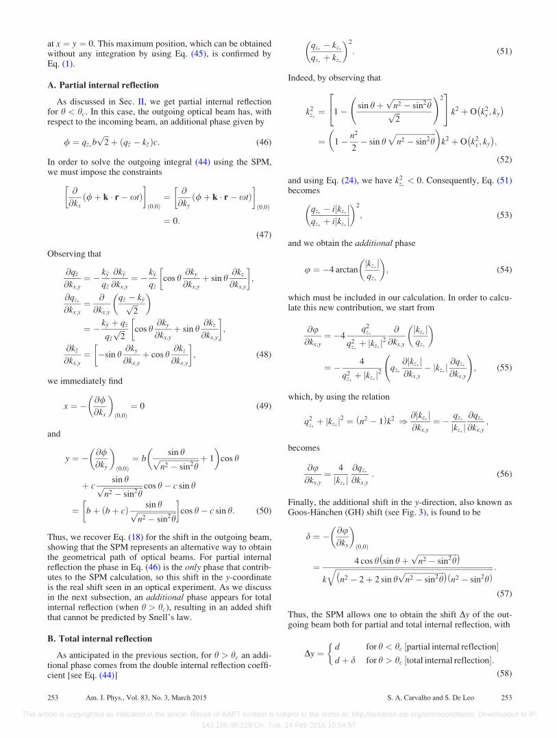
In Fig. 2, we plot the critical angle
hc ¼ arcsin1�
ffiffiffiffiffiffiffiffiffiffiffiffiffin2 � 1pffiffiffi2p
!(22)
as a function of the refractive index n. This curve separatesthe partial and total reflection zones. We conclude this sec-tion by observing that for
1�ffiffiffiffiffiffiffiffiffiffiffiffiffin2 � 1pffiffiffi2p � �1; (23)
which implies
n �ffiffiffiffiffiffiffiffiffiffiffiffiffiffiffiffiffi4þ 2
ffiffiffi2pq
; (24)
we always find total internal reflection.
III. MAXWELL’S EQUATIONS AND
TRANSMISSION COEFFICIENTS
In this section, we calculate the transmission and reflectioncoefficient at each interface using Maxwell’s equations.1,2
The phase of the outgoing beam will be then used to
calculate the path of the optical beam using the stationaryphase method21–23
The plane wave solution of
@xx þ @yy þ @zz �@tt
c2
� �E r; tð Þ ¼ 0 (25)
is given by
exp ½iðkxxþ kyyþ kzz� xtÞ�; (26)
providing that k ¼ffiffiffiffiffiffiffiffiffiffiffiffiffiffiffiffiffiffiffiffiffiffiffiffiffik2
x þ k2y þ k2
z
q¼ x=c. Given the linear-
ity of Eq. (25), a superposition of these plane wave solutionswill also be a solution. Many lasers emit beams that approxi-mate a Gaussian profile,18,19,30 given by
E r; tð Þ ¼ E0
w20
4p
ðdkx dky exp � k2
x þ k2y
�w2
0=4h i
� exp i k r� xtð Þ½ �; (27)
where w0 is the waist size of the beam. Observe that forffiffiffiffiffiffiffiffiffiffiffiffiffiffiffik2
x þ k2y
q k (which constitutes the paraxial approxima-
tion), the previous integral can be calculated analytically andleads to Eq. (1).
Given that the transmitted (refracted) beam is along the~z-axis, it is convenient to rewrite Maxwell’s equations byusing the coordinate system ðx; ~y; ~zÞ:
@xx þ @~y~y þ @~z~z � n2 ~zð Þ @tt
c2
� �Eleft r; tð Þ ¼ 0 (28)
with
nð~zÞ ¼ 1 for ~z < 0
n for ~z > 0:
�(29)
The plane wave solution is now given by
exp ½iðkxxþ k~y ~y � xtÞ�
�exp ½ik~z~z� þ Rleft exp ½�ik~z~z� for ~z < 0
Tleft exp ½iq~z~z� for ~z > 0;
�(30)
where
k~y
k~z
� �¼ RðhÞ ky
kz
� �(31)
and
fq~y ; q~zg ¼ k~y ;ffiffiffiffiffiffiffiffiffiffiffiffiffiffiffiffiffiffiffiffiffiffiffiffiffiffiffiffiffin2k2 � k2
x � k2~y
q� �: (32)
Observe that the ~y-component of the wave number does notchange because the discontinuity is along the ~z-axis.31
Imposing the continuity of Eleft and @~z Eleft at the point wherethe refractive index is discontinuous (i.e. ~z ¼ 0) we find
Rleft ¼k~z � q~z
k~z þ q~zand Tleft ¼
2k~z
k~z þ q~z: (33)
At the second interface, it is convenient to use the coordinatesystem ðx; y�; z�Þ and solve the Maxwell equation
Fig. 2. The critical angle hc is plotted as a function of the refractive index n.
The forbidden region (shaded) represents incidence angles for which the
refracted beam at the left interface cannot reach the down boundary. For
n >ffiffiffiffiffiffiffiffiffiffiffiffiffiffiffiffiffiffi4þ 2
ffiffiffi2pp
, we always find total internal reflection.
251 Am. J. Phys., Vol. 83, No. 3, March 2015 S. A. Carvalho and S. De Leo 251
This article is copyrighted as indicated in the article. Reuse of AAPT content is subject to the terms at: http://scitation.aip.org/termsconditions. Downloaded to IP:
143.106.96.229 On: Tue, 24 Feb 2015 10:54:57

@xx þ @y�y� þ @z�z� � n2 z�ð Þ@tt
c2
� �Edown r; tð Þ ¼ 0 (34)
with
n z�ð Þ ¼n for z� <
affiffiffi2p
1 for z� >affiffiffi2p :
8>><>>: (35)
The plane wave solution is
exp i kxxþ qy�y� � xtð Þ½ �
�exp iqz�z�½ � þ Rdown exp �iqz�z�½ � for z� <
affiffiffi2p
Tdown exp ikz�z�½ � for z� >affiffiffi2p ;
8>><>>:
(36)
where
qy�
qz�
� �¼ R
p4
� �k~y
q~z
� �(37)
and
fky� ; kz�g ¼ fqy� ;ffiffiffiffiffiffiffiffiffiffiffiffiffiffiffiffiffiffiffiffiffiffiffiffiffiffik2 � k2
x � q2y�
qg: (38)
As with the first interface, the y�-component of the wavenumber is not modified because the discontinuity of the sec-ond interface is along the z�-axis. By matching Eq. (36) at~z ¼ a=
ffiffiffi2p
, we find
Rdown ¼qz� � kz�
qz� þ kz�
exp 2iqz�
affiffiffi2p
� �and
Tdown ¼2qz�
qz� þ kz�
exp i qz� � kz�ð Þaffiffiffi2p
� �: (39)
We can use the result obtained for the down interface to findthe result for the up interface. Making the substitutionsðkz� ; qz� Þ ! �ðkz� ; qz� Þ and a=
ffiffiffi2p! ða� bÞ=
ffiffiffi2p
, we findthe reflection and transmission coefficients for the up inter-face to be
Rup ¼qz� � kz�
qz� þ kz�
exp 2iqz�
b� affiffiffi2p
� �and
Tup ¼2qz�
qz� þ kz�
exp i qz� � kz�ð Þb� affiffiffi
2p
� �: (40)
In a similar way, the reflection and transmission coefficientsfor the right interface can be directly obtained from the coef-ficients calculated for the left interface. Replacing k~z $ q~z
and observing that the discontinuity is now located at ~z ¼ c,we obtain
Rright ¼q~z � k~z
q~z þ k~zexp 2iq~zc½ � and
Tright ¼2q~z
q~z þ k~zexp i q~z � k~zð Þc½ �: (41)
Finally, the outgoing transmission coefficient is given by
Tout ¼ TleftRdownRupTright
¼ 4k~zq~z
q~z þ k~zð Þ2qz� � kz�
qz� þ kz�
� �2
� exp iqz�bffiffiffi2pþ i q~z � k~zð Þc
h i: (42)
The spatial phases of the optical beam in the differentregions are then
in : kxxþ kyyþ kzz ¼ kxxþ k~y ~y þ k~z~z;
left! down : kxxþ k~y ~y þ q~z~z ¼ kxxþ qy�y� þ qz�z�;
down! up : kxxþ qy�y� � qz�z�;
up! right : kxxþ qy�y� þ qz�z� ¼ kxxþ k~y ~y þ q~z~z;
out : kxxþ k~y ~y þ k~z~z ¼ kxxþ kyyþ kzz:
(43)
The outgoing beam, which as expected is parallel to theincoming one, is then given by18,19
Eout r; tð Þ ¼ E0
w20
4p
ðdkx dky
4k~zq~z
q~z þ k~zð Þ2qz� � kz�
qz� þ kz�
� �2
� exp � k2x þ k2
y
�w20
4
� �
� exp i qz�bffiffiffi2pþ q~z � k~zð Þcþ k r�xt
h in o:
(44)
In the following section, we use the stationary phase method(SPM) to calculate the position of the maximum of the out-going beam, and consequently the position of the opticalbeam, at the exit of our dielectric system. The calculationbased on the SPM thus represents an alternative method toobtain the optical path. More importantly, the SPM calcula-tion also allows us to obtain the Goos-H€anchen shift.
IV. THE OPTICAL PATH VIA THE STATIONARY
PHASE METHOD
The SPM is a basic principle of asymptotic analysis thatapplies to oscillatory integrals.22,23 The main idea of theSPM relies on the cancelation of sinusoids with rapidly vary-ing phase, so the dominant contribution to the integral comeswhen the phase is stationary; that is, where the derivative ofthe phase vanishes. This means that many sinusoids with thesame phase can be added together constructively, giving riseto a peaked function. To illustrate this principle let us con-sider the incoming beam given in Eq. (27). In order to solvethe integral we impose that
@
@kxk r� xtð Þ
� �0;0ð Þ¼ @
@kyk r� xtð Þ
� �0;0ð Þ¼ 0:
(45)
The subscript (0, 0) tells us that the derivatives have to becalculated at the maximum value of the convolution func-tion, where kx ¼ ky ¼ 0. For the incoming optical beam ofEq. (27), the convolution function is a Gaussian distribution;consequently, the maximum of the incoming beam is located
252 Am. J. Phys., Vol. 83, No. 3, March 2015 S. A. Carvalho and S. De Leo 252
This article is copyrighted as indicated in the article. Reuse of AAPT content is subject to the terms at: http://scitation.aip.org/termsconditions. Downloaded to IP:
143.106.96.229 On: Tue, 24 Feb 2015 10:54:57
at x ¼ y ¼ 0. This maximum position, which can be obtainedwithout any integration by using Eq. (45), is confirmed byEq. (1).
A. Partial internal reflection
As discussed in Sec. II, we get partial internal reflectionfor h < hc. In this case, the outgoing optical beam has, withrespect to the incoming beam, an additional phase given by
/ ¼ qz�bffiffiffi2pþ ðq~z � k~zÞc: (46)
In order to solve the outgoing integral (44) using the SPM,we must impose the constraints
@
@kx/þ k r� xtð Þ
� �0;0ð Þ¼ @
@ky/þ k r� xtð Þ
� �0;0ð Þ
¼ 0:
(47)
Observing that
@q~z
@kx;y¼ � k~y
q~z
@k~y
@kx;y¼ � k~y
q~zcos h
@ky
@kx;yþ sin h
@kz
@kx;y
� �;
@qz�
@kx;y¼ @
@kx;y
q~z � k~yffiffiffi2p
� �
¼ � k~y þ q~z
q~z
ffiffiffi2p cos h
@ky
@kx;yþ sin h
@kz
@kx;y
� �;
@k~z
@kx;y¼ �sin h
@ky
@kx;yþ cos h
@kz
@kx;y
� �; (48)
we immediately find
x ¼ � @/@kx
� �0;0ð Þ¼ 0 (49)
and
y ¼ � @/@ky
� �0;0ð Þ¼ b
sin hffiffiffiffiffiffiffiffiffiffiffiffiffiffiffiffiffiffiffiffiffin2 � sin2hp þ 1
� �cos h
þ csin hffiffiffiffiffiffiffiffiffiffiffiffiffiffiffiffiffiffiffiffiffi
n2 � sin2hp cos h� c sin h
¼ bþ bþ cð Þ sin hffiffiffiffiffiffiffiffiffiffiffiffiffiffiffiffiffiffiffiffiffin2 � sin2hp
� �cos h� c sin h: (50)
Thus, we recover Eq. (18) for the shift in the outgoing beam,showing that the SPM represents an alternative way to obtainthe geometrical path of optical beams. For partial internalreflection the phase in Eq. (46) is the only phase that contrib-utes to the SPM calculation, so this shift in the y-coordinateis the real shift seen in an optical experiment. As we discussin the next subsection, an additional phase appears for totalinternal reflection (when h > hc), resulting in an added shiftthat cannot be predicted by Snell’s law.
B. Total internal reflection
As anticipated in the previous section, for h > hc an addi-tional phase comes from the double internal reflection coeffi-cient [see Eq. (44)]
qz� � kz�
qz� þ kz�
� �2
: (51)
Indeed, by observing that
k2z�¼ 1� sin hþ
ffiffiffiffiffiffiffiffiffiffiffiffiffiffiffiffiffiffiffiffiffin2 � sin2hpffiffiffi2p
!224
35 k2 þ O k2
x ; ky
¼ 1� n2
2� sin h
ffiffiffiffiffiffiffiffiffiffiffiffiffiffiffiffiffiffiffiffiffin2 � sin2h
p� �k2 þ O k2
x ; ky
;
(52)
and using Eq. (24), we have k2z�< 0. Consequently, Eq. (51)
becomes
qz� � ijkz� jqz� þ ijkz� j
� �2
; (53)
and we obtain the additional phase
u ¼ �4 arctanjkz� jqz�
� �; (54)
which must be included in our calculation. In order to calcu-late this new contribution, we start from
@u@kx;y
¼ �4q2
z�
q2z�þ jkz� j
2
@
@kx;y
jkz� jqz�
� �
¼ � 4
q2z�þ jkz� j
2qz�
@jkz� j@kx;y
� jkz� j@qz�
@kx;y
!; (55)
which, by using the relation
q2z�þ jkz� j
2 ¼ n2 � 1ð Þk2 ) @jkz� j@kx;y
¼ � qz�
jkz� j@qz�
@kx;y;
becomes
@u@kx;y
¼ 4
jkz� j@qz�
@kx;y: (56)
Finally, the additional shift in the y-direction, also known asGoos-H€anchen (GH) shift (see Fig. 3), is found to be
d ¼ � @u@ky
� �0;0ð Þ
¼ 4 cos h sin hþffiffiffiffiffiffiffiffiffiffiffiffiffiffiffiffiffiffiffiffiffin2 � sin2hp
k
ffiffiffiffiffiffiffiffiffiffiffiffiffiffiffiffiffiffiffiffiffiffiffiffiffiffiffiffiffiffiffiffiffiffiffiffiffiffiffiffiffiffiffiffiffiffiffiffiffiffiffiffiffiffiffiffiffiffiffiffiffiffiffiffiffiffiffiffiffiffiffiffiffiffiffiffiffiffiffiffiffiffiffin2 � 2þ 2 sin h
ffiffiffiffiffiffiffiffiffiffiffiffiffiffiffiffiffiffiffiffiffin2 � sin2hp
n2 � sin2hð Þq :
(57)
Thus, the SPM allows one to obtain the shift Dy of the out-going beam both for partial and total internal reflection, with
Dy ¼d for h < hc ½partial internal reflection�d þ d for h > hc ½total internal reflection�:
�(58)
253 Am. J. Phys., Vol. 83, No. 3, March 2015 S. A. Carvalho and S. De Leo 253
This article is copyrighted as indicated in the article. Reuse of AAPT content is subject to the terms at: http://scitation.aip.org/termsconditions. Downloaded to IP:
143.106.96.229 On: Tue, 24 Feb 2015 10:54:57

In concluding this section, we recall that the GH shift d can-not be obtained using Snell’s law. This additional shift is dueto the presence of evanescent waves in the air zones close tothe down and up interfaces and cannot be predicted solelyfrom geometry.32 This phenomenon is similar to the timedelay encountered in quantum-mechanical scattering.33–35
V. CONCLUSIONS AND OUTLOOK
In this article, we have shown the value of the SPM as amathematical tool in determining the path of optical beams.Our analysis here, which is carried out for s-polarized waves,can be extended to p-polarized waves, and gives rise to anoutgoing beam transmission coefficient1,18,19,36
Tpð Þ
out ¼4n2k~zq~z
q~z þ n2k~zð Þ2qz� � n2kz�
qz� þ n2kz�
!2
� exp iqz�bffiffiffi2pþ q~z � k~zð Þc
h i: (59)
For partial internal reflections, the SPM reproduces the ge-ometrical result predicted by Snell’s law: Dy ¼ d. For totalinternal reflections, the SPM predicts Dy ¼ d þ d, thusaccounting for the GH shift. The additional shift d is propor-tional to the wavelength of the incoming beam, with a nu-merical pre-factor of order unity [see Eq. (57)]. The order ofmagnitude of the GH shift for a double (total) internal reflec-tion is thus relatively small and this makes experimentalobservations difficult. Note that red lasers (k � 0:633 lm),whose beam waist is w0 ¼ 1 mm undergo a shift ofd � 10�4w0. Because the shift depends on the number of in-ternal reflections, to make such an experimental measure-ment possible,37 we need to amplify the effect byconsidering, for example, a band of N dielectric blocks. Inthis case, the final GH shift will be given by Nd.
To guarantee two internal reflections in each block, weimpose that the z�-component at the exit point (Pright) be thesame as the z�-component at the entrance point (Pleft). Thiscondition implies [see Eq. (16)] that c tanðp=4� wÞ ¼ b,which, after simple algebraic manipulations, leads to
c ¼ n2 þ 2 sin hffiffiffiffiffiffiffiffiffiffiffiffiffiffiffiffiffiffiffiffiffin2 � sin2hp
n2 � 2 sin2hb: (60)
In a forthcoming work, we intend to analytically calculatethe integral in Eq. (44) to obtain the outgoing beam profile.This calculation can be carried out by approximating thetransmission coefficient in view of the result obtained inSec. IV.
ACKNOWLEDGMENTS
The authors gratefully thank the referees for theirconstructive comments and useful suggestions. The authorsalso thank the Fapesp (SaC) and the CNPq (SdL) for thefinancial support.
a)Electronic mail: [email protected]. Born and E. Wolf, Principles of Optics (Cambridge U.P., Cambridge,
1999).2B. E. A. Saleh and M. C. Teich, Fundamentals of Photonics (Wiley &
Sons, New Jersey, 2007).3M. Kryjevskaia, M. R. Stetzer, and P. R. L. Heron, “Student understand-
ing of wave behavior at a boundary: The relationships among wave-
length, propagation speed, and frequency,” Am. J. Phys. 80, 339–347
(2012).4R. Heller, “On the teaching of the Snell-Descartes law of refraction,” Am.
J. Phys. 16, 356–357 (1948).5J. W. Shirley, “An early experimental determination of Snell’s law,” Am.
J. Phys. 19, 507–508 (1951).6C. V. Bertsch and B. A. Greenbaum, “New apparatus for Snell’s law,”
Am. J. Phys. 26, 340 (1958).7H. E. Bates, “An analogue model for teaching reflection and refraction of
waves,” Am. J. Phys. 48, 275–277 (1980).8D. Drosdoff and A. Widom, “Snell’s law from an elementary particle
viewpoint,” Am. J. Phys. 73, 973–975 (2005).9J. J. Lynch, “Snell’s law with large blocks,” Phys. Teach. 45, 180–182
(2007).10L. I. Shiff, Quantum Mechanics (McGraw-Hill, New York, 1955).11C. Cohen-Tannoudji, B. Diu, and F. Lalo€e, Quantum Mechanics (Wiley,
Paris, 1977).12S. Longhi, “Quantum-optical analogies using photonic structures,” Laser
Photon Rev. 3, 243–261 (2009).13X. Chen, X. J. Lu, Y. Ban, and C. F. Li, “Electronic analogy of the Goos-
H€anchen effect: A review,” J. Opt. 15, 033001-1–12 (2013).14H. F. Meiners, “Optical analog of quantum-mechanical barrier
penetration,” Am. J. Phys. 33, xviii (1965).15P. L. Garrido, S. Goldstein, J. Lukkarinen, and R. Tumulka, “Paradoxical
reflection in quantum mechanics,” Am. J. Phys. 79, 1218–1231 (2011).16G. Zhu and C. Singh, “Surveying students understanding of quantum
mechanics in one spatial dimension,” Am. J. Phys. 80, 252–259
(2012).17S. De Leo and P. Rotelli, “Localized beams and dielectric barriers,”
J. Opt. A 10, 115001-1–5 (2008).18S. De Leo and P. Rotelli, “Laser interacting with a dielectric block,” Eur.
Phys. J. D 61, 481–488 (2011).19S. De Leo and P. Rotelli, “Resonant laser tunneling,” Eur. Phys. J. D 65,
563–570 (2011).20M. Selmke and F. Cichos, “Photonic Rutherford scattering: A classical
and quantum mechanical analogy in ray and wave optics,” Am. J. Phys.
81, 405–413 (2013).21E. Wigner, “Lower limit for the energy derivative of the scattering phase
shift,” Phys. Rev. 98, 145–147 (1955).22R. B. Dingle, Asymptotic Expansions: Their Derivation and Interpretation
(Academic Press, London 1973).23N. Bleistein and R. Handelsman, Asymptotic Expansions of Integrals
(Dover, New York, 1975).24D. C. Look, “Novel demonstration of total internal reflection,” Am. J.
Phys. 49, 794 (1981).25E. Richard and V. Keuren, “Refractive index measurement using total in-
ternal reflection,” Am. J. Phys. 73, 611–615 (2005).26F. Goos and H. H€anchen, “Ein neuer und fundamentaler Versuch zur total-
reflexion,” Ann. Phys. 436, 333–346 (1947).27S. R. Seshadri, “Goos-H€anchen beam shift at total internal reflection,”
J. Opt. Soc. Am. A 5, 583–585 (1988).
Fig. 3. We illustrate here that, for h > hc, the geometrical path predicted by
Snell’s law suffers an additional shift at each internal reflection known as
the Goos-H€anchen shift. The net result for our situation is that the outgoing
light beam suffers a lateral shift d, which can be calculated using the station-
ary phase method (SPM).
254 Am. J. Phys., Vol. 83, No. 3, March 2015 S. A. Carvalho and S. De Leo 254
This article is copyrighted as indicated in the article. Reuse of AAPT content is subject to the terms at: http://scitation.aip.org/termsconditions. Downloaded to IP:
143.106.96.229 On: Tue, 24 Feb 2015 10:54:57

28A. Aiello, “Goos-H€anchen and Imbert-Federov shifts: A novel
perspective,” New J. Phys. 14, 013058-1–12 (2012).29K. Y. Bliokh and A. Aiello, “Goos-H€anchen and Imbert-Fedorov beam
shifts: An overview,” J. Opt. 15, 014001-1–16 (2013).30M. Andrews, “The evolution of free wave packets,” Am. J. Phys. 76,
1102–1107 (2008).31F. Mooney, “Snell’s law equivalent to the conservation of tangential
momentum,” Am. J. Phys. 19, 385 (1951).32F. P. Zanella, D. V. Magalhes, M. M. Oliveira, R. F. Bianchi, and L.
Misoguti, “Frustrated total internal reflection: A simple application and
demonstration,” Am. J. Phys. 71, 494–496 (2003).
33K. Yasumoto and Y. Oishi, “A new evaluation of the Goos-H€anchen shift
and associated time delay,” J. Appl. Phys. 54, 2170–2176 (1983).34W. van Dijk and K. A. Kiers, “Time delay in simple one dimensional sys-
tems,” Am. J. Phys. 60, 520–527 (1992).35L. de la Torre, “Wave packet distortion and time delay,” Am. J. Phys. 65,
123–125 (1997).36C. Bahrim and W. T. Hsu, “Precise measurements of the refractive indices
for dielectrics using an improved Brewster angle method,” Am. J. Phys.
77, 337–344 (2009).37N. J. Harrick, “Study of physics and chemistry of surfaces from frustrated
total internal reflections,” Phys. Rev. Lett. 4, 224–226 (1960).
255 Am. J. Phys., Vol. 83, No. 3, March 2015 S. A. Carvalho and S. De Leo 255
This article is copyrighted as indicated in the article. Reuse of AAPT content is subject to the terms at: http://scitation.aip.org/termsconditions. Downloaded to IP:
143.106.96.229 On: Tue, 24 Feb 2015 10:54:57
![A COURSE FORPHD MATHEMATICAL STATISTICS … and representation theorems for stationary processes, in the spirit of [9]. It must be said, however, that it represents only a selection](https://img.dokumen.tips/doc/110x75/5ab30acd7f8b9aea528de573/a-course-forphd-mathematical-statistics-and-representation-theorems-for-stationary.jpg)