Embed Size (px)
Citation preview
Energy Conversion. Vol. 13, pp.1-5. Pergamon Press, 1973. Printed in Great Britain
The Use of Solar Energy for Residential Heating H, G, LORSCHf
(Received 3 July 1972)
Introduction Residential and commercial space and hot water
heating accounts for approximately 20 per cent of the US total energy consumption; residential space heating alone accounts for 12 per cent. It is therefore apparent that a major alleviation of the current energy shortage would result if a significant fraction of these require- ments could be satisfied by the use of non-conventional energy sources. In the light of these facts a team of researchers at the University of Pennsylvania has been investigating the applicability of solar heating, thermal energy storage and off-peak air conditioning to in- dustrialized housing. One of the goals of this work is the development of space heating and cooling systems and components suitable for large scale production in order to achieve conservation of natural resources and better utilization of electric power. This paper describes part of the work dealing with solar heating systems.
Description of Heating System A typical heating system using solar energy is shown
in Fig. 1. Its major components are identified in the figure. The system operates as follows:
2, ~
Valve,,~
-.at-..---
Thermal energy
Tr < Tt h storage
I--I',, T,r,~ t
) © , Pump --,=-----
Heating coil
_ _ iliary / heat
/ e x c h a n g e r
(Conventional furnace)
T e = Collector temperature
T r = Room temperature
T. = Thermal energy storage temperature
Tth ,= Room thermostat setting
Fan contro l :Same as for conventional heating system pump cont ro l :On: Tr,cTthandTc>Tr
or' Tr ~: Tth andT.> Tr
or r~> r,
Aux i l ia ry heater : On'. Tr < T~ and pump is o f f
Fig. 1. Solar heating system diagram.
t National Center for Energy Management and Power, Univer- sity of Pennsylvania, Philadelphia, Pennsylvania 19104.
(a) When the room thermostat calls for heat, the water pump is turned on provided either the storage temperature or the collector temperature is above the room temperature. As long as the collector temperature is above the room temperature the loop obtains heat from the collector. All valves in Fig. 1 permit flow in the left-right direction. The fan is turned on by a con- ventional control related to the plenum temperature and delivers hot air to the house.
(b) When the room thermostat calls for heat and the collector temperature is below the room temperature but the storage temperature is above the room tem- perature, the valve in the lower left of Fig. 1 switches position and the house draws heat from storage.
(c) When neither the collector nor the storage unit is at a higher temperature than the house and the room thermostat calls for heat, the auxiliary heating unit (which is a conventional furnace) operates and heats the house. The pump is off under these conditions.
(d) When the house does not require heat and the solar collector is hotter than the storage system, the pump circulates fluid from the collector to the storage unit.
The control rules for pump, fan and auxiliary heating system are listed on the bottom of Fig. 1. The arrange- ment of the entire system incorporating two alternate ways for TES (thermal energy storage) inside a 3-bedroom house is shown in Fig. 2.
Itector
'or
rage
Fig. 2. Installation of solar heating system in a house.
Solar Collector The results of many tests [2, 4-8, 10, 11, 13, 15] show
that the most suitable type of solar collector for buildings
H. G. LORSCH
is the flat plate collector which consists of a transparent front plate, one or more insulating zones and an absorb- ing rear plate. Heat is delivered from the absorber to the house heating system by a convective loop. Thermal insulation is placed behind the absorber plate to prevent overheating of the building during the day and excessive heat loss at night.
The most favorable orientation for solar collectors is at an inclination angle to the horizontal equal to latitude plus 15 ° [17]. Making the collector vertical deviates little from this optimum over most of the United States, reduces undesirable summer heating and permits rela- tively easy incorporation of the collector into the wall of the building.
Southern orientation of the wall containing the solar collector is desirable, but not absolutely essential. For example, a vertical collector facing southwest or south- east receives almost 80 per cent as much solar energy as a collector facing due south. This is practically the greatest reduction that could occur because, for a deviation from south greater than 45 ° , the collector could be shifted to a different wall. Complete data for various orientations of vertical collectors over most geographical locations of the United States during critical winter months are summarized in Fig. 3. The figure shows that orientation due south is desirable but by no means mandatory for a solar heated house. In fact, a 25 ° deviation imposes only a 5 per cent penalty and a 33 ° deviation a 10 per cent penalty on solar heat availability.
IOO
9O ec
g" ~c ~g
,g
~ 3c
2¢
I 1 1 1 " 4 ~ i 0 ~ a | I l I o 2o 30 5 60 70 8o 90
South Southeast, East, Southwest V~st
Wall Azimuth (degrees deviation from South)
Fig. 3..A~mqthal variation of solar radlat/on on a vertical surface. (December and January, latitudes 30-450N.)
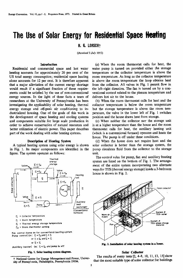
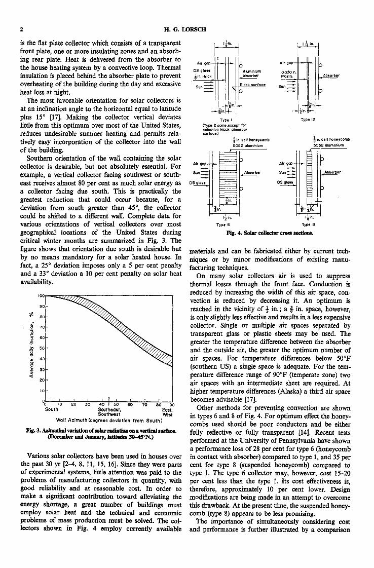
Various solar collectors have been used in houses over the past 30 yr [2-4, 8, 11, 15, 16]. Since they were parts of experimental systems, little attention was paid to the problems of manufacturing collectors in quantity, with good reliability and at reasonable cost. In order to make a significant contribution toward alleviating the energy shortage, a great number of buildings must employ solar heat and the technical and economic problems of mass production must be solved. The col- lectors shown in Fig. 4 employ currently available
I
Atr gap--- ~ ~ I DS glale ~Alumlnlum in. thick I_ absorber
Sun ~ lack surface
Type I (Type 2 same,except for eelect¢ve block absorber" =urfoce)
~ln, cell honeycomb 5052 otumlnlum
r
I~ I --1 I~in .
Type 6
Sun._..~.[I -II
Type f2
~ ln. cell honeycomb 5052 alum Inlum
Sun ~.~ =~,beorber DS glees
3
Type 8 Fig. 4. Solar collector erom sections.
materials and can be fabricated either by current tech- niques or by minor modifications of existing manu- facturing techniques.
On many solar collectors air is used to suppress thermal losses through the front face. Conduction is reduced by increasing the width of this air space, con- vection is reduced by decreasing it. An optimum is reached in the vicinity of ½ in.; a { in. space, however, is only slightly less effective and results in a less expensive collector. Single or multiple air spaces separated by transparent glass or plastic sheets may be used. The greater the temperature difference between the absorber and the outside air, the greater the optimum number of air spaces. For temperature differences below 50°F (southern US) a single space is adequate. For the tem- perature difference range of 90°F (temperate zone) two air spaces with an intermediate sheet are required. At higher temperature differences (Alaska) a third air space becomes advisable [17].
Other methods for preventing convection are shown in types 6 and 8 of Fig. 4. For optimum effect the honey- combs used should be poor conductors and be either fully reflective or fully transparent [14]. Recent tests performed at the University of Pennsylvania have shown a performance loss of 28 per cent for type 6 (honeycomb in contact with absorber) compared to type 1, and 35 per cent for type 8 (suspended honeycomb) compared to type 1. The type 6 collector may, however, cost 15-20 per cent less than the type 1. Its cost effectiveness is, therefore, approximately 10 per cent lower. Design modifications are being made in an attempt to overcome this drawback. At the present time, the suspended honey- comb (type 8) appears to be less promising.
The importance of simultaneously considering cost and performance is further illustrated by a comparison

The Use of Solm. Enm~ for ResMeaflal Space Heating 3
of the test results for types 1 and 2 solar collectors. While type 2 (selective black) performed approximately 15 per cent better, its cost on a mass produced basis is 20 per cent higher making the type 2 less cost effective than the type 1.
Thermal Energy Storage Thermal energy storage (TES) for solar space heating
can be accomplished in two ways: through sensible heat or through latent heat. In sensible heat storage the temperature of a substance having a high specific heat, e.g. water, is raised or lowered. In latent heat storage a substance having a high heat of fusion is alternately melted and frozen.
Heat Transfer Loops A solar heating system contains two heat transfer
loops: (1) collector to storage and (2) storage to room or to furnace heat exchanger (see Figs. 1 and 2). The loops can be either separate or combined. They can employ either liquid or gaseous heat transfer media. The advantages and disadvantages of different media are summarized in Table 1. Additional consideration must be given to the compatibility of the heat transfer loops with the method of heating the living space. In a house with hot-water baseboard heaters or radiant panels a liquid loop would be preferable, while an air loop would be preferred in a house with a hot air dis- tribution system.
System Study Over most of the geographic area of the United
States, the reliability and intensity of sunshine and the space heat requirements are such that solar energy cannot be used economically as the sole source for comfort heating. To do so would require an inordinately large amount of thermal energy storage which would he used very inefficiently only a few times a year in order to provide heat during a series of successive cloudy days. A stand-by heating system is therefore required.
Tybout and LSf [17] showed that, for the north- eastern part of the country, the most economic amount of solar heating is below 50 per cent of the total annual heating demand. Thus, one should consider the solar
Thermal energy storage capacity, kWh I o zo 3o 4o 5o so
150 , l L = i =
b 4.0
~" ' NO so la r c o l l e c t o r E~ ~. 13oi (convent iona l heat ing 0
s y s t e m ) 3 . 5 0 ! '2° °
I10 ,-
" = o Ioo q f t ( 2 6 m Z , ' 3.o = o ~ So la r co l l ec to r
90 ~ 2.5
i " °
80
"tO 560 sq ft (52 - 2.0 ~ c S o l a r c o l l e c t o r
= 6o i K 1.5 5c i4c o
[ 3 o
i 20 ' " <~ 0.5
I0
I t m
Thermal energy storage capacity (1000 B,t.u.)
t~ . 5. ~ commmt~=~ f=. d/~mnm mime ef mkur eatleeto¢ and thermal imcnly i t o n ~ devices. [1500 fl~ (140 m s) house;
w ~ Ix; (1960) we~ller.]
heating system as a fuel saver only. The stand-by system should have the same capacity as a conventional heating system and the economic trade-off is between the acquisi- tion cost of the solar collector/storage system and the fuel saving between conventional and stand-by systems.
In order to provide a realistic comparison in fuel consumption between a conventional space heating system and a system utilizing solar heat/thermal energy storage, a planned residential development currently under construction was chosen. The project is of con- ventional frame construction on a concrete foundation. The insulating properties are within the minimum standards recently published by the United States De- partment of Housing and Urban Development [9]. The original design was easily adaptable to the introduction of the solar collector and thermal energy storage systems into the units. The solar collectors were placed into the
Table 1. Heat transfer loop trade-offs
Function Component Advantages Disadvantages
Transfer of heat from solar Air loop Simple. No night freezing Large temperature differences between solar collector to TES unit collector and air and between air and
TES unit. Large surface areas required. Dirt. Fan power and noise
Requires careful design to avoid night freezing. Consequences of leaks
Same Liquid loop
Transfer of heat from TES Air loop unit to rooms
Same Water loop
Smaller sized piping and pump. Low solar collector temperature and high efficiency
Simple. May use same air loop for air conditioning. Possible to control humi- dity
Simple. Least expensive
Fan power and noise
Not adaptable to air-conditioning

H. G. LORSCH
Table 2. SoM heated house projected co~ developmeat
Year Present(1972) 1975 1980
(Total (Total (Total heating heating heating
Operating costs (gas) (Uni0 season) (Unit) season) (Unit) season) Wholesale/10 e B.t.u. 0.30 0.50 0.90 Distribution/106 B.t.u. 0.80 0.95 1.20
Total 1" 10 $154 1"45 $203 2.10 $294
Capital costs (Uni0 (Total) Solar collector (560 ft 2) $2.50/ftz $1400 Heat storage (150,000 B.t.u.) $4/1000 B.t.u. 600 Piping, pump, controls 350
(Uni0 (Total) (Uni0 (Total) $2.00/ft~ $1120 $1.50/ft~ $840 $2.50/1000 B.t.u. 375 $2.00/1000 B.t.u. 300
350 350
Present system 2350 1850 1490 Optimized system $2350 $1760 $1340
(Heating (Heating (Heating Savings in gas season) season) season)
100 B.t.u. 65 65 65 Savings as yearly ~o of capital cost 3~o 5~o 10~
south-facing walls and the thermal storage fitted into the existing utility space.
Using Washington D.C. weather data for 1960, the gas consumption for space heating of a typical 3-bedroom townhouse unit was determined for various heating systems with the aid of a series of computer programs [12] in common usage for the performance analysis of heating and cooling systems. A solar collector efficiency of 45 per cent was assumed, and no energy was collected for insolation rates below 80 B.t.u./ft2.hr (21.4 langley/ hr). These are very conservative assumptions as shown in [1]. All thermal energy storage (TES) was taken to be through latent heat.
Space heating using a conventional natural gas furnace requires 139 MCFt of gas. Adding a 280 ft 2 (26 m 2) solar collector without storage reduces this require- ment by 16 MCF (11.5 per cent). With thermal energy storage of 50,000 B.t.u. (14"6 kWh) another 15 MCF are saved. Doubling the storage further reduces con- sumption by 6 MCF-102 MCF for a total gas saving of 27 per cent. Using a 560 ft z (52 m 9) solar collector with 0, 75,000 and 150,000 B.t.u. (0, 22 and 44 kWh) storage, respectively, leads to savings of 19, 43 and 57 MCF (41 per cent). No system tests have been performed yet to confirm these results; component test data show, however, that they are on the conservative side.
The results of the analysis are shown graphically in Fig. 5. For the smaller collector, adding 50,000 B.t.u. storage approximately doubles its efficiency, while doubling this storage increases the saving by 40 per cent only. In other words, the second 50,000 B.t.u. TES is used only 40 per cent as much as the first. A similar situation exists for the larger (560 ft 2) solar collector as is apparent from a comparison of the ordinates in Fig. 5. The figure also shows that the 150,000 B.t.u.
$ 1MCF ----- I000 ft a -- 28.3 ms.
storage represents all the storage capacity that can be used with a 280 fC collector; increasing the storage further is not accompanied by any additional savings in gas consumption. For the 560 ft 2 collector, this stage is reached at approximately 250,000 + B.t.u. storage.
All of the stated values are somewhat higher than average for a house of that size. The reason is that the room temperature was kept at 72°F (22°C) throughout the year and that heating or cooling was used at all times to maintain that temperature. Thus, on many fall and spring days, heat was used during the night and air conditioning during the day. No advantage was taken of the thermal lag due to building structure and insulation which tends to reduce the heating/cooling requirements. In reality, most home owners do not maintain their homes at a constant temperature through- out the year. The heating/cooling energy consumption in an average house of that size could therefore be 20--30 per cent lower than the quoted numbers.
Future cost projections are summarized in Table 2. Although presently solar heating is comparable in cost to electric resistance heating and is therefore not econo- mical compared to gas heating in the northeastern United States, a moderate improvement in manufac- turing techniques with resulting reductions in systems costs could make solar heating competitive with gas heating by 1980.
As the energy shortage becomes more acute, it can be expected that ways and means will be found by Government organizations for accelerating the use of alternate energy sources. Such measures could take the form of tax incentives, outright cash payments, or refusal of gas service to consumers not utilizing uncon- ventional energy sources. The last two methods are presently used by many United States utilities to en- courage or discourage certain services, while the first one is in extensive use by local, state and Federal governments for a variety of purposes.

The Use of Solar Energy for Residential Slmee Heating
Acknowledgement--The author wishes to thank his colleagues at the University of Pennsylvania for their contributions to the preparation of this paper, particularly Dr. Manfred Altman for his detailed review of the manuscript and his constructive com- ments, Mr. John-Robertson Cox for the architectural design, Dr. Steven Freedman for the preparation of Tables 1 and 2, Mr. Alan Saunders for the collector tests, Mr. Lawrence Spielvogel and Mr. James Dudley for the computer analysis, Dr. Maria Telkes for her extensive background, Dr. Iraj Zandi for his project leader- ship and the National Science Foundation for sponsorship of the work.
References [1] M. Altman, M. Telkes and M. Wolf, Energy Conversion 12,
53 (1972). [2] Anon., Space Heating With Solar Energy. MIT Press, Cam-
bridge (1954). [3] R. Bliss, Jr., UN Conference on New Sources of Power,
E35-$30 (1961). [4] F. H. Bridgers, D. D. Paxton and R. W. Haines, Heating,
Piping and Air Conditioning, 27, 165 (1957).
5
[5] H. Buchberg, O. A. Lalude and D. K. Edwards, Solar Energy 13, 193 (1971).
[6] J. P. Chiou, M. M. EI-Wakil and J. A. Duffle, Solar Energy 9, 73 (1965).
[7] D. J. Close, Solar Energy 7, 117 (1963). [8] F. Daniels, Direct Use of the Sun's Energy. Yale University
Press, New Haven (1964). [9] Federal Housing Administration, Minimum Property Stand-
ards for One and Two Living Units, MPS 300, Interim Revision 51A, Department of Housing and Urban Development, Wash- ington D.C. (1971).
[10] H. C. Hottel and B. B. Woertz, Trans. Am. Soc. Mech. Engrs 64, 91 (1942).
[11] G. O. G. L6fet al., ASHR.4EJ177 (1966). [12] R. F. Meriwether et al., Energy Systems Analysis Series.
Ross F. Meriwether, San Antonio. [13] M. K. Selcuk, Solar Energy 8, 57 (1964). [14] H. Tabor, Solar Energy 12, 549 (1969). [15] M. Telkes, Heating and Ventilating Reference Section, p. 68
(1949). [16] H. E. Thomason, Solar Energy 10, 17 (1966). [17] R. A. Tybout and G. O. G. l.~f, Solar House Heating. Re-
sources for the Future, Washington D.C. (1969).