Embed Size (px)
Citation preview

The use of RELAP5The use of RELAP5--3D3D©© code code in the OECD/NEA in the OECD/NEA
VVERVVER--1000 CT1000 CT--1 and CT1 and CT--2 Benchmark2 Benchmark
A. Frisani, A. Frisani, C. ParisiC. Parisi,, F. DF. D’’AuriaAuriaSan Piero a Grado Nuclear Research Group
DIMNP - University of Pisa - ITALY
RELAP5-3D© Users Seminar Holiday Inn SunSpree Resort – West Yellowstone – USA
16 – 18 August 2006

•• ObjectivesObjectives
•• IntroductionIntroduction
•• VVER1000 CTVVER1000 CT--1 benchmark1 benchmark•• RELAP5RELAP5--3D3D©© ThermalThermal--Hydraulic Modeling Hydraulic Modeling
•• NESTLENESTLE Neutronic Modeling & Neutronic Modeling & PARCS V2.6PARCS V2.6 comparison comparison
•• Sample Transient Results Sample Transient Results
•• VVER1000 CTVVER1000 CT--2 benchmark2 benchmark•• RELAP5RELAP5--3D3D©© ThermalThermal--Hydraulic ModelingHydraulic Modeling
•• Neutronic ModelingNeutronic Modeling
•• Sample Results Sample Results
•• Conclusions and Future WorkConclusions and Future Work
CONTENTSCONTENTS

•• To assess the THTo assess the TH--3D NK system codes 3D NK system codes nodalizationsnodalizationsfor analyzing VVER1000 transientsfor analyzing VVER1000 transients
•• To assess the RELAP5To assess the RELAP5--3D3D©© for coupled TH/3D NK for coupled TH/3D NK calculations in hexagonal geometrycalculations in hexagonal geometry
•• To assess the RELAP5To assess the RELAP5--3D3D©© for 3D vessel simulationsfor 3D vessel simulations
OBJECTIVESOBJECTIVES

The transient test scenario is as follows:The transient test scenario is as follows:
•• At reactor power 29.45% Nom MCP#3 is switched onAt reactor power 29.45% Nom MCP#3 is switched on
•• After switching on MCP#3 the reactor power increases to 29.8%NnoAfter switching on MCP#3 the reactor power increases to 29.8%Nnomm
•• Pressurizer water level decreases from 744 cm to 728 cmPressurizer water level decreases from 744 cm to 728 cm
•• Water level in the Steam Generator #3 decreases with 9 cmWater level in the Steam Generator #3 decreases with 9 cm
•• The flow rate in loop #3 reverses back to normal at the 13th secThe flow rate in loop #3 reverses back to normal at the 13th sec. of the . of the switching on MCP#3. The timing is consistent with reactivity incswitching on MCP#3. The timing is consistent with reactivity increase, as rease, as observed through the reactor power set pointsobserved through the reactor power set points
V1000V1000--CT1 BenchmarkCT1 Benchmark
V1000V1000--CT1 CT1 BenchmarkBenchmark: : originallyoriginally simulatedsimulated at UNIPI at UNIPI bybyRELAP5/PARCS RELAP5/PARCS coupledcoupled codescodes
New New modellingmodelling forfor RELAP5RELAP5--3D3D
Transient test scenario Transient test scenario repeatedrepeated activitiesactivities stillstill in progressin progress

THERMALTHERMAL--HYDRAULIC MODELINGHYDRAULIC MODELING
TT--H core model developed from the one already H core model developed from the one already completed (and used for 0completed (and used for 0--D NK calculations) for D NK calculations) for allowing the coupling with 3allowing the coupling with 3--D NK D NK 29 independent 29 independent core TH channelscore TH channels
4 Loops with 4 Steam Generator4 Loops with 4 Steam Generator
ECCS ModelingECCS Modeling
Number of Number of Heat StructuresHeat Structures = = 28982898
Number of Number of Mesh PointsMesh Points = = 1970019700
Number of Number of VolumesVolumes = = 22632263
Number of Number of JunctionsJunctions = = 23492349

TT--H Model: H Model: RELAP5RELAP5--3D3D©©
VVERVVER--1000 nodalization1000 nodalization

ACTIVE ZONE
REFLECTOR
REFLECTOR
REF
LEC
TOR
TT--H Model: Core NodalizationH Model: Core Nodalization

Fuel assembly with Enrichment 2.0%
Fuel assembly with Enrichment 3.0%
Fuel assembly with Enrichment 3.3%
Fuel assembly with Enrichment 3.3% *
Radial reflector
1 1.219
2 1.283
3 1.311
4 1.553
5 1.360
6 1.409
7 1.391
29 0.0
8 1.603
9 1.271
10 1.286
11 1.676
12 1.578
13 0.909
29 0.0
14 1.271
15 1.213
16 1.271
17 1.246
18 1.065
29 0.0
19 1.286
20 1.271
21 1.489
22 1.053
29 0.0
23 1.676
24 1.246
25 1.053
29 0.0
26 1.578
27 1.065
29 0.0
28 0.909
29 0.0
29 0.0
1
2
1 1 –– Type of fuel assemblyType of fuel assembly2 2 –– Burnup Burnup MWd/kgUMWd/kgU
Cross Section Modelling Cross Section Modelling –– FA TypesFA Types

•• Calculation performed with Calculation performed with HELIOSHELIOS Lattice Physics CodeLattice Physics Code
•• Generated Generated XSecXSec Libraries for BOLLibraries for BOL
•• Each of 28 composition divided by 10 layer Each of 28 composition divided by 10 layer 28 x 10 = 280 Fuel 28 x 10 = 280 Fuel CompositionsCompositions
•• 3 Compositions (# 281, 282, 283) used for Bottom, Radial and To3 Compositions (# 281, 282, 283) used for Bottom, Radial and Top Reflectorp Reflector
•• ADF directly included in the Cross Section valuesADF directly included in the Cross Section values
Cross Section FormatCross Section Format
Automatic Cross Section ProcessingAutomatic Cross Section Processing
NEMTAB & NEMTAB & NEMTABR text files NEMTABR text files
for for
RoddedRodded & & UnRoddedUnRodded
Fuel CompositionsFuel Compositions
OBTAINING OBTAINING XSEC IN XSEC IN NESTLENESTLE
&& PARCS PARCS FORMATFORMAT
•• Cross Section Cross Section reference reference valuesvalues and and variation variation coefficientscoefficients automatically automatically calculated by calculated by FORTRAN FORTRAN program program NESTLECONVNESTLECONV
•• 4D Linear Interpolation4D Linear Interpolation for for reference value reference value •• Minimum Least Square Minimum Least Square methodmethod for variation for variation coefficientscoefficients
•• User User can selectcan select : : Libraries Dimension & Libraries Dimension & Reference conditions Reference conditions for the interpolationfor the interpolation

33--D Neutronic Model D Neutronic Model –– NESTLE vs. PARCS codesNESTLE vs. PARCS codes
PARCSPARCS•• USUS--NRC reference 3D Neutron Kinetic Code NRC reference 3D Neutron Kinetic Code –– v 2.6 v 2.6 •• Solution of the twoSolution of the two--group diffusion equations system with the group diffusion equations system with the
Triangular Polynomial Expansion Nodal method (TPEN) for HexagonaTriangular Polynomial Expansion Nodal method (TPEN) for Hexagonal l Geometry Geometry
•• Coupled with RELAP5 via Parallel Virtual Machine (Coupled with RELAP5 via Parallel Virtual Machine (PVMPVM) protocol) protocol
NESTLENESTLE•• FullyFully integratedintegrated in RELAP5in RELAP5--3D3D©©•• Based on Nodal Expansion Based on Nodal Expansion MethodMethod (NEM)(NEM)•• Internally coupled with the TH Internally coupled with the TH modulemodule (RELAP5(RELAP5--3D)3D)
Comparison executed in order to increase Comparison executed in order to increase confidence in NK codes resultsconfidence in NK codes results

3D NK Model3D NK Model
•• 46424642 NK nodesNK nodes
•• Radial, Upper and Radial, Upper and Bottom Reflector Bottom Reflector modeledmodeled
•• 2222 axial layer ( 2 for axial layer ( 2 for top/bottom reflector, top/bottom reflector, 20 for the core)20 for the core)
••280280 unroddedunrodded + + 110110roddedrodded compositionscompositions
•• Delay neutron Delay neutron constants & fractions constants & fractions specified for each specified for each compositioncomposition
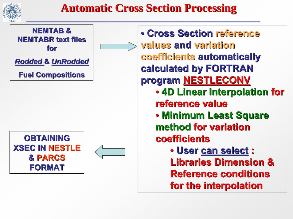
HZP/HFPHZP/HFP ConditionsConditionsSteady State calculations executed for HZP and HFP SS conditionsSteady State calculations executed for HZP and HFP SS conditions::
HZPHZP 3 MW; 3 MW; XSecXSec reference values for reference values for TfTf = Tm = 552 K = Tm = 552 K
HFPHFP 3000 MW; 3000 MW; XSecXSec reference values forreference values for TfTf = 900 K, Tm = 567 K= 900 K, Tm = 567 K
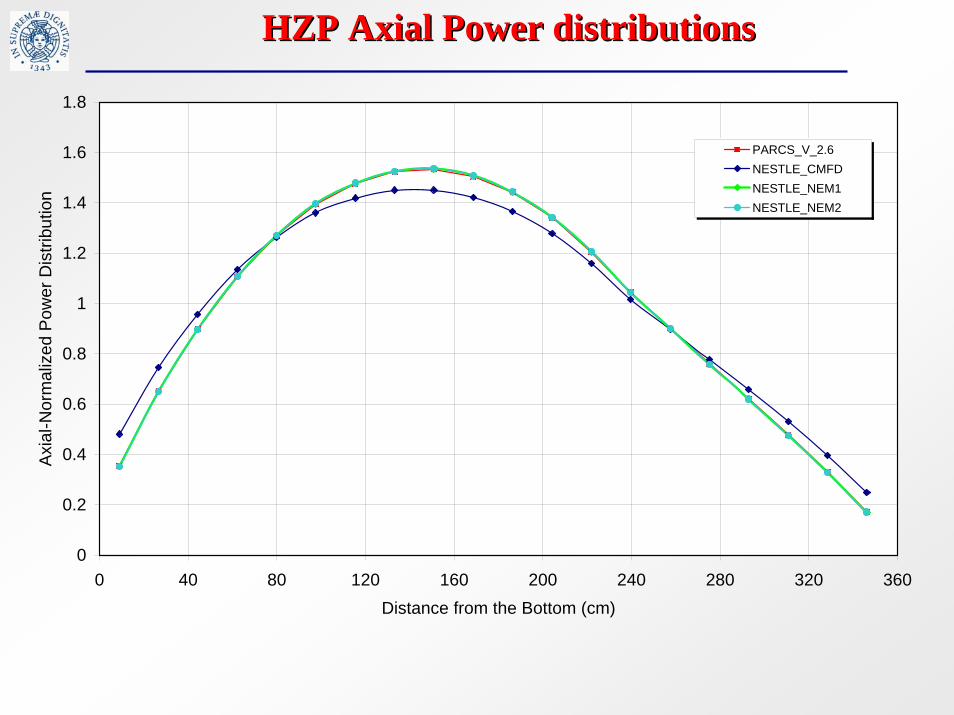
HZP HZP AxialAxial Power Power distributionsdistributions
0
0.2
0.4
0.6
0.8
1
1.2
1.4
1.6
1.8
0 40 80 120 160 200 240 280 320 360Distance from the Bottom (cm)
Axi
al-N
orm
aliz
ed P
ower
Dis
tribu
tion
PARCS_V_2.6NESTLE_CMFDNESTLE_NEM1NESTLE_NEM2

Radial Power at HZPRadial Power at HZP conditionsconditions
HZP HZP
PARCS (TPEN) PARCS (TPEN) –– NESTLE (NEM)NESTLE (NEM)
HZP HZP
PARCS (TPEN) PARCS (TPEN) –– NESTLE (CMFD)NESTLE (CMFD)

HFP SS Axial PowerHFP SS Axial Power
0
0.2
0.4
0.6
0.8
1
1.2
1.4
1.6
0 40 80 120 160 200 240 280 320 360
Distance from the Bottom (cm)
Axi
al-N
orm
aliz
ed P
ower
Dis
trib
utio
n
Power ParcsNESTLE_CMFDNESTLE_NEM1NESTLE_NEM2

Radial Power at HFP conditions Radial Power at HFP conditions
HFP HFP
PARCS (TPEN) PARCS (TPEN) –– NESTLE (CMFD)NESTLE (CMFD)HFP HFP
PARCS (TPEN) PARCS (TPEN) –– NESTLE (NEM)NESTLE (NEM)

V1000V1000--CT1 CT1 –– Sample Transient Results Sample Transient Results
MCP3 Pressure drop
0.000E+00
1.000E+05
2.000E+05
3.000E+05
4.000E+05
5.000E+05
6.000E+05
7.000E+05
8.000E+05
0.0 20.0 40.0 60.0 80.0 100.0 120.0
time (s)
Pres
sure
(Pa)
MCP3 pressure drop-experimental dataMCP3 pressure drop-RELAP5-3D

V1000V1000--CT1 CT1 –– Sample Transient ResultsSample Transient Results
Temperature hot leg 4
561.500
562.000
562.500
563.000
563.500
564.000
564.500
565.000
565.500
566.000
566.500
0.0 20.0 40.0 60.0 80.0 100.0 120.0
time (s)
tem
pera
ture
(K)
Temperature hot leg 4-experimental dataTemperature hot leg 4-RELAP5-3D

V1000V1000--CT1 CT1 –– Sample Transient ResultsSample Transient Results
Temperature hot leg 3
548.000
550.000
552.000
554.000
556.000
558.000
560.000
562.000
564.000
566.000
568.000
0.0 20.0 40.0 60.0 80.0 100.0 120.0
time (s)
tem
pera
ture
(K)
Temperature hot leg 3-experimental dataTemperature hot leg 3-RELAP5-3D

V1000V1000--CT1 CT1 –– Final ConsiderationsFinal Considerations
•• RELAP5RELAP5--3D3D©© model model waswas ableable toto simulate simulate plantplant transienttransient
•• FurtherFurther worksworks neededneeded on the SG model on the SG model forforeliminate some eliminate some discrepanciesdiscrepancies
•• 3D NK model 3D NK model confirmedconfirmed PARCS PARCS resultsresultsNEM NEM methodmethod increasedincreased accuracyaccuracy of one of one orderorder of of magnitudemagnitude

V1000V1000--CT2 BenchmarkCT2 Benchmark
The purpose of the V1000CTThe purpose of the V1000CT--2 benchmark is three2 benchmark is three--fold:fold:•• To test flow mixing models (CFD, coarseTo test flow mixing models (CFD, coarse--mesh and mesh and
mixing matrix), against mixing matrix), against measured datameasured data and in and in codecode--toto--code comparisoncode comparison..
•• To fully test the To fully test the 33--D neutronics/vessel thermalD neutronics/vessel thermal--hydraulic couplinghydraulic coupling..
•• To evaluate discrepancies between predictions of To evaluate discrepancies between predictions of coupled codes in bestcoupled codes in best--estimate transient estimate transient simulations.simulations.
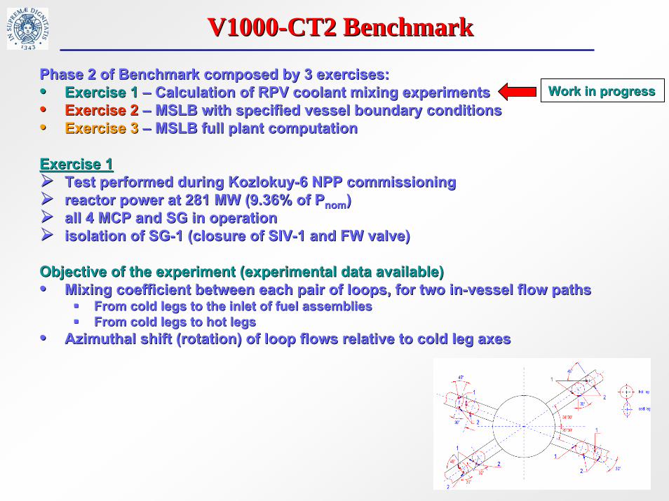
Phase 2 of Benchmark composed by 3 exercises:Phase 2 of Benchmark composed by 3 exercises:•• Exercise 1Exercise 1 –– Calculation of RPV coolant mixing experimentsCalculation of RPV coolant mixing experiments•• Exercise 2Exercise 2 –– MSLB with specified vessel boundary conditionsMSLB with specified vessel boundary conditions•• Exercise 3Exercise 3 –– MSLB full plant computationMSLB full plant computation
Exercise 1Exercise 1Test performed during KozlokuyTest performed during Kozlokuy--6 NPP commissioning6 NPP commissioningreactor power at 281 MW (9.36% of reactor power at 281 MW (9.36% of PPnomnom))all 4 MCPall 4 MCP and SG in operationand SG in operationisolation of SGisolation of SG--1 (closure of SIV1 (closure of SIV--1 and FW valve) 1 and FW valve)
Objective of the experiment (experimental data available)Objective of the experiment (experimental data available)•• Mixing coefficient between each pair of loops, for two inMixing coefficient between each pair of loops, for two in--vessel flow pathsvessel flow paths
From cold legs to the inlet of fuel assembliesFrom cold legs to the inlet of fuel assembliesFrom cold legs to hot legsFrom cold legs to hot legs
•• AzimuthalAzimuthal shift (rotation) of loop flows relative to cold leg axesshift (rotation) of loop flows relative to cold leg axes
V1000V1000--CT2 BenchmarkCT2 Benchmark
Work in progressWork in progress
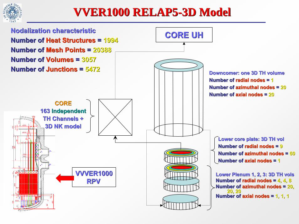
VVER1000 RELAP5VVER1000 RELAP5--3D Model3D Model
DowncomerDowncomer: one 3D TH volume: one 3D TH volumeNumber of Number of radial nodesradial nodes = = 11Number of Number of azimuthalazimuthal nodesnodes = = 2020Number of Number of axial nodesaxial nodes = = 2020
Nodalization characteristicNodalization characteristicNumber of Number of Heat StructuresHeat Structures = = 19941994Number of Number of Mesh PointsMesh Points = = 2038820388Number of Number of VolumesVolumes = = 30573057Number of Number of JunctionsJunctions = = 54725472
LowerLower Plenum 1, 2, 3: 3D TH Plenum 1, 2, 3: 3D TH volsvolsNumber of Number of radial nodesradial nodes = = 4, 4, 84, 4, 8Number of Number of azimuthal nodesazimuthal nodes = = 20, 20,
20, 2020, 20Number of Number of axial nodesaxial nodes = = 1, 1, 11, 1, 1
CORE UHCORE UH
LowerLower core core plateplate: 3D TH : 3D TH volvolNumber of Number of radial nodesradial nodes = = 99Number of Number of azimuthalazimuthal nodesnodes = = 6060Number of Number of axial nodesaxial nodes = = 11
CORECORE163 163 IndependentIndependentTH TH ChannelsChannels + + 3D NK model3D NK model
VVVER1000 VVVER1000 RPVRPV

VVER1000 3D Model VVER1000 3D Model –– Sensitivity analyses Sensitivity analyses
GeometryGeometryDowncomer with Downcomer with 2020 azimuthal nodesazimuthal nodesDowncomer with Downcomer with 4040 azimuthal nodesazimuthal nodesDowncomer with Downcomer with 6060 azimuthal nodesazimuthal nodes
Downcomer azimuthal loss coefficientsDowncomer azimuthal loss coefficientsReynolds Reynolds forwardforward//reversereverse lossloss coefficient=coefficient= 0.10.1ReynoldsReynolds forwardforward//reversereverse lossloss coefficient=coefficient= 11
3D NK3D NKFDM FDM solutionsolution techniquetechniqueNEM solution NEM solution techniquetechnique
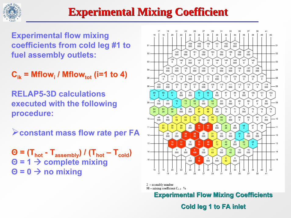
ExperimentalExperimental Mixing Mixing CoefficientCoefficient
Experimental flow mixing coefficients from cold leg #1 to fuel assembly outlets:
Cik = Mflowi / Mflowtot (i=1 to 4)
RELAP5-3D calculations executed with the following procedure:
constant mass flow rate per FA
Θ = (Thot - Tassembly) / (Thot – Tcold)Θ = 1 complete mixingΘ = 0 no mixing
ExperimentalExperimental FlowFlow Mixing Mixing CoefficientsCoefficients
ColdCold legleg 1 1 toto FA FA inletinlet

VVER1000 3D Model VVER1000 3D Model –– prelimaryprelimary calculationscalculations
Time t= 0 secondsTime t= 0 seconds Time t= 1 secondsTime t= 1 seconds
Preliminary calculationsPreliminary calculations executed to assess code capabilitiesexecuted to assess code capabilitiesUserUser’’s defined transients defined transient: : injection of cold waterinjection of cold water (10 deg. below (10 deg. below
average temperature)average temperature) complete mixing after complete mixing after 1010 secssecsFlow mixing coefficients from cold leg 1 to fuel assembliesFlow mixing coefficients from cold leg 1 to fuel assemblies
Time t= 2 secondsTime t= 2 seconds

VVER1000 3D Model VVER1000 3D Model –– prelimaryprelimary calculationscalculations
Time t= 10 secondsTime t= 10 secondsTime t= 5 secondsTime t= 5 seconds
Flow mixing coefficients from cold leg 1 to fuel assembliesFlow mixing coefficients from cold leg 1 to fuel assemblies
Time t= 15 secondsTime t= 15 seconds Time t= 19 secondsTime t= 19 seconds

CONCLUSIONS and FUTURE WORKCONCLUSIONS and FUTURE WORK
For VVER1000 CT1 benchmark:For VVER1000 CT1 benchmark:ConsideringConsidering the absolute errorsthe absolute errors againstagainst experimental dataexperimental data, , we we can conclude transient results trends are well predicted by can conclude transient results trends are well predicted by RELAP5RELAP5--3D3D©© and the model developed is capable to properly and the model developed is capable to properly simulate transient scenario for a VVER1000 simulate transient scenario for a VVER1000 Works in progress to Works in progress to improveimprove TH model TH model The error inThe error in radial power distributionsradial power distributions between between RELAP5/PARCSRELAP5/PARCSand and RELAP5RELAP5--3D3D©© shows the same trend both for HZP and HP shows the same trend both for HZP and HP conditions. The symmetric error distribution shows that the erroconditions. The symmetric error distribution shows that the error r has to be related to solver methodshas to be related to solver methods
For VVER1000 CT2 benchmark:For VVER1000 CT2 benchmark:A Reactor Vessel 3D TH & NK model was developedA Reactor Vessel 3D TH & NK model was developedRELAP5RELAP5--3D is capable to simulate the 3D is capable to simulate the vesselvessel mixing phenomenamixing phenomenaWork in progress for Work in progress for qualifyqualify model and execute exercises 1 & 2model and execute exercises 1 & 2Code capabilities increase Code capabilities increase neededneeded for handling large model (3D for handling large model (3D TH + NK + Plant) for execution of 3TH + NK + Plant) for execution of 3rdrd exercise (MSLB + Vessel 3D)exercise (MSLB + Vessel 3D)


![Www.inl.gov Measurements of Version 3.0 (Beta) RELAP5-3D RELAP5-3D International Users Seminar 2010 [insert optional photo(s) here] Sep 20-23, 2010](https://img.dokumen.tips/doc/110x75/56649efb5503460f94c0e440/wwwinlgov-measurements-of-version-30-beta-relap5-3d-relap5-3d-international.jpg)