Embed Size (px)
Citation preview
The Ultimate Immersive Experience: Panoramic 3D Video Acquisition
Christian Weissig, Oliver Schreer, Peter Eisert, Peter Kauff
Fraunhofer Heinrich-Hertz Institute, Einsteinufer 37, 10587 Berlin, Germany {Christian.Weissig,Oliver.Schreer,Peter.Eisert,Peter.Kauff}@hhi.fraunhofer.de
Abstract. The paper presents a new approach on an omni-directional omni-stereo multi-camera system that allows the recording of panoramic 3D video with high resolution and quality and display in stereo 3D on a cylindrical screen. It has been developed in the framework of the TiME Lab at Fraunhofer HHI, an experimental platform for immersive media and related content creation. The new system uses a mirror rig to enable a multi-camera constellation that is close to the concept of concentric mosaics. A proof of concept has shown that the systematical approximation error related to concentric mosaics is negligible in practice and parallax-free stitching of stereoscopic video panoramas can be achieved with high 3D quality and for arbitrary scenes with depth ranges from 2 meters to infinity.
Keywords: Panoramic Imaging, Ultra-High Definition, 3D Video Panorama, Omni-Directional Cameras, Omni-Stereo Panorama, Concentric Mosaics
1 Introduction
It is widely accepted that concept of immersive media is one of the most promising market segments of future technology. One feature of immersive media is panoramic imaging using large cylindrically or spherically curved screens, often in combination with multi-projection systems providing ultra-high resolution by exact juxtaposition and blending of multiple projector images [1][2][3][4][5]. Being lost in niche markets like theme parks for a long time, these applications are now migrating into new market segments like event and exhibition technology, training centers or even entertainment. Typical applications are dome projections (e.g. in planetariums), giant screen cinemas (e.g. re-opening of digital Cinerama theatres) or immersive 180° or 360° surround video (e.g. simulation and training centers) [6][7][8]. In future, they may even address immersive viewing in new types of cinema theatres or other public venues, or, to its end, in immersive home entertainment.
In February 2010, the Fraunhofer Heinrich-Hertz-Institute (HHI) in Berlin, Germany, has opened its ‘Tomorrow’s Immersive Media Experience Laboratory (TiME Lab)’, an experimental platform for immersive media and related content creation. The TiME Lab uses up to 14 HD projectors for panoramic 2D and 3D projection at a cylindrical 180° screen with a resolution of 7k x 2k as well as a ‘Wave Field Synthesis (WFS)’ sound system with 128 loudspeakers [9].
Apart from multi-projection, a further main challenge of panoramic imaging is to create live footage supporting these special video formats in combination with ultra-high resolution. One solution is, in analogy to multi-projection, to use multiple cameras where the single cameras look into different directions such the resulting images can be stitched seamlessly to large panoramic views. The technology of such omni-directional camera systems has a long tradition. First systems that use multiple cameras and mirrors to achieve full surround capture with high image resolution have already been used in the 60s by Ub Iwerks for Disney theme park productions [10]. Since then many further mirror-based system approaches have been proposed (e.g. [11]). Other approaches place a hyperboloid mirror in front of a single camera to capture panoramic views [12][13]. Today, the advances and ongoing miniaturization of digital video cameras enables more compact systems and several commercial companies offer omni-directional cameras for a wide range of applications [14][15][16][17][18][19][20][21]. Good overviews about different approaches on panoramic imaging are given in [22][23].
The term “3D panoramic video” is often used for 360° viewing capability in a 2D panorama. However, in this context, two video panoramas of the same scene but with different perspective are considered, one for the left and one for the right eye in order to allow stereoscopic 3D. Although the concept of omni-directional cameras for capturing 2D video panoramas is well understood and a lot of efficient systems are already available, capturing of 3D video panoramas is still a challenge and a partly unsolved problem. Against this background, this paper mainly presents a prototype system of a new 3D omni-directional camera, which allows an almost error-free panoramic 3D video acquisition by using a special mirror rig. After a short review of capturing systems for panoramic 2D video, the 3D approach is explained in more detail. Meanwhile, a proof of concept has been achieved by first test shootings and the content has been presented in HHI’s TiME Lab during the “Berlinale” film festival in Berlin on February 2011.
2 Review of Omni-Directional Imaging and Panoramic 2D Video
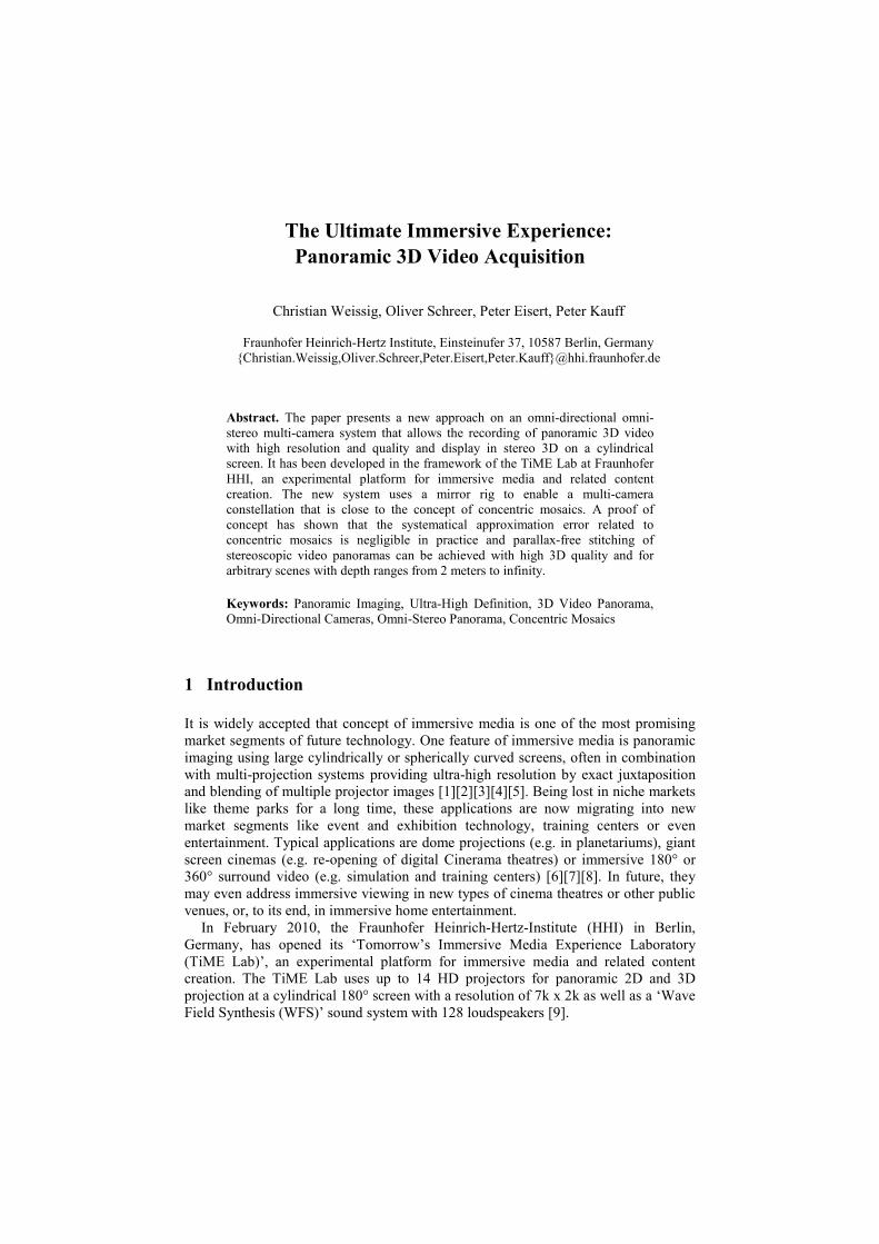
As known from projective geometry, the optimal multi-camera arrangement for capturing panoramic videos requires that the focal points of all camera views coincide in a common point (see left drawing in Figure 1) [22][23]. In case of capturing static 2D panoramas, this condition is usually achieved by rotating a single camera at a tripod with a revolving camera head. For video, however, this approach is impractical due to the need of using multiple cameras on one hand and the physical dimensions of each camera on other hand. Hence, many commercial solutions capture video panoramas with the star-like approach from Figure 1 (right) [15][18][21]. In this case the focal points of all cameras are located on a common circle, while the optical axes are perpendicular to the arc. This approach works reasonably well as long as only far distant objects appear in the scene. However, the existence of a non-zero parallax angle does not allow seamless stitching in case of close objects in the overlap area.
A suitable approximation of the optimal solution from Figure 1 (left) can be achieved by using special mirror-rigs. If all cameras and mirrors are arranged correctly, it is possible to superimpose the virtual images of all focal points in one
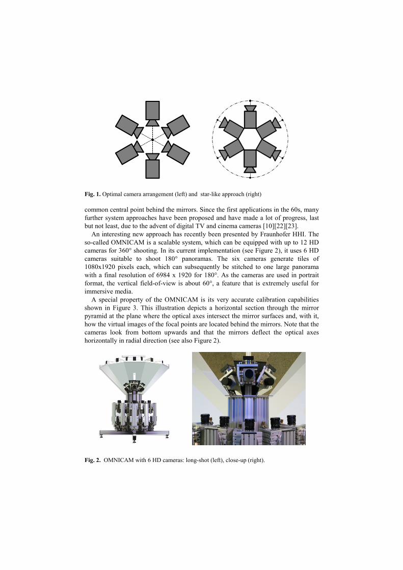
Fig. 1. Optimal camera arrangement (left) and star-like approach (right)
common central point behind the mirrors. Since the first applications in the 60s, many further system approaches have been proposed and have made a lot of progress, last but not least, due to the advent of digital TV and cinema cameras [10][22][23].
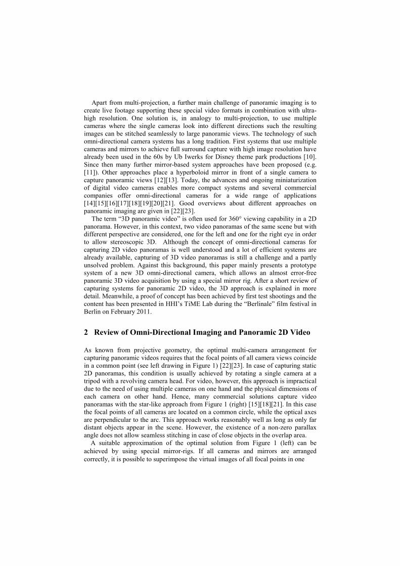
An interesting new approach has recently been presented by Fraunhofer HHI. The so-called OMNICAM is a scalable system, which can be equipped with up to 12 HD cameras for 360° shooting. In its current implementation (see Figure 2), it uses 6 HD cameras suitable to shoot 180° panoramas. The six cameras generate tiles of 1080x1920 pixels each, which can subsequently be stitched to one large panorama with a final resolution of 6984 x 1920 for 180°. As the cameras are used in portrait format, the vertical field-of-view is about 60°, a feature that is extremely useful for immersive media.
A special property of the OMNICAM is its very accurate calibration capabilities shown in Figure 3. This illustration depicts a horizontal section through the mirror pyramid at the plane where the optical axes intersect the mirror surfaces and, with it, how the virtual images of the focal points are located behind the mirrors. Note that the cameras look from bottom upwards and that the mirrors deflect the optical axes horizontally in radial direction (see also Figure 2).
Fig. 2. OMNICAM with 6 HD cameras: long-shot (left), close-up (right).
In a first step the rig is calibrated such that all virtual images of the focal points coincide in the centre C of the mirror pyramid (see Figure 3, left). This initial state refers to the optimal camera arrangement from Figure 1 (left). It is obtained by very precise optical measurements in the laboratory.
Fig. 3. Optimal mirror-based arrangement (left), radial off-centered arrangement (right).
Although this initial and optimal state allows a parallax-free stitching for scenes with a depth range from zero to infinity, it is not really suitable under real working conditions. If all cameras have a common focal point in the center of the mirror pyramid, there would be no overlap between the different tiles due to a hard cut at the mirror edges. Hence, there is no possibility to blend pixels between adjacent image tiles. In former applications like theme park productions this drawback has been concealed by segmented projection screens.
However, this is not acceptable any longer for seamless projection of video panoramas in future immersive media applications. Hence, at least some slight overlap between adjacent image tiles is needed. In order to obtain overlaps, the focal points of the cameras have to be moved symmetrically by precise actuators out of the center in radial direction (Figure 3, right). By this off-center adjustment of the focal points, it becomes possible to regulate a scene-adaptive trade-off between sufficient overlaps for blending and parallax-free stitching. In practice, the OMNICAM is usually operated with a radial-shift of about 5 mm, resulting in a blending area of about 10 pixels and a parallax-free stitching of scenes with a depth range from 2m to infinity. Figure 4 shows an example of the whole OMNICAM processing for a sports production with a particularly high depth range of the captured scene at the outer left and right blending areas. Meanwhile, the OMNICAM has been used under real working conditions for a couple of 2D panorama productions shown in the TiME Lab.
a) b)
c) d)
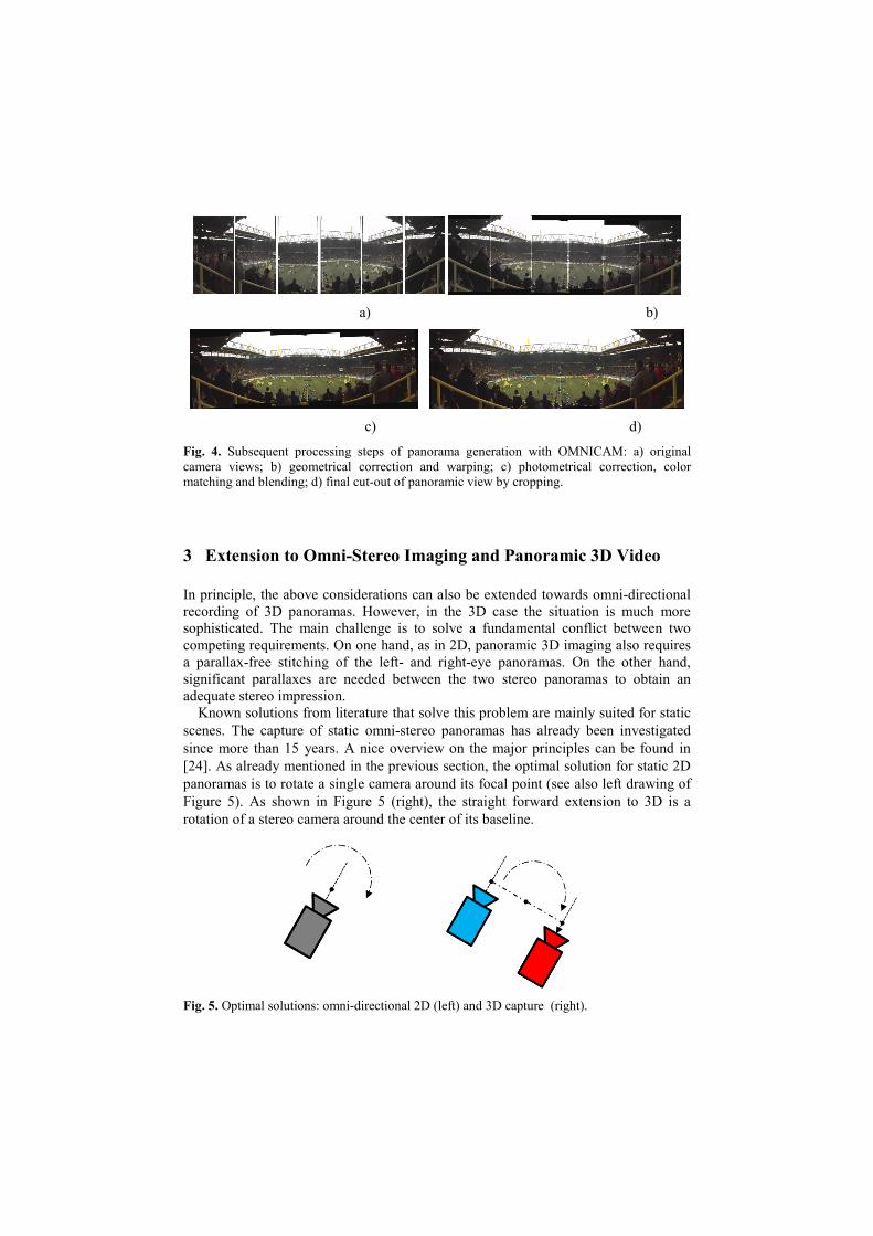
Fig. 4. Subsequent processing steps of panorama generation with OMNICAM: a) original camera views; b) geometrical correction and warping; c) photometrical correction, color matching and blending; d) final cut-out of panoramic view by cropping.
3 Extension to Omni-Stereo Imaging and Panoramic 3D Video
In principle, the above considerations can also be extended towards omni-directional recording of 3D panoramas. However, in the 3D case the situation is much more sophisticated. The main challenge is to solve a fundamental conflict between two competing requirements. On one hand, as in 2D, panoramic 3D imaging also requires a parallax-free stitching of the left- and right-eye panoramas. On the other hand, significant parallaxes are needed between the two stereo panoramas to obtain an adequate stereo impression.
Known solutions from literature that solve this problem are mainly suited for static scenes. The capture of static omni-stereo panoramas has already been investigated since more than 15 years. A nice overview on the major principles can be found in [24]. As already mentioned in the previous section, the optimal solution for static 2D panoramas is to rotate a single camera around its focal point (see also left drawing of Figure 5). As shown in Figure 5 (right), the straight forward extension to 3D is a rotation of a stereo camera around the center of its baseline.
Fig. 5. Optimal solutions: omni-directional 2D (left) and 3D capture (right).
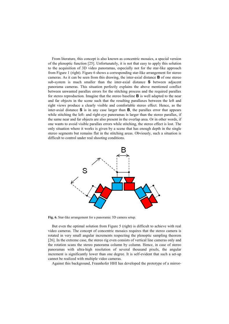
From literature, this concept is also known as concentric mosaics, a special version of the plenoptic function [25]. Unfortunately, it is not that easy to apply this solution to the acquisition of 3D video panoramas, especially not for the star-like approach from Figure 1 (right). Figure 6 shows a corresponding star-like arrangement for stereo cameras. As it can be seen from this drawing, the inter-axial distance B of one stereo sub-system is much smaller than the inter-axial distance S between adjacent panorama cameras. This situation perfectly explains the above mentioned conflict between unwanted parallax errors for the stitching process and the required parallax for stereo reproduction. Imagine that the stereo baseline B is well adapted to the near and far objects in the scene such that the resulting parallaxes between the left and right views produce a clearly visible and comfortable stereo effect. Hence, as the inter-axial distance S is in any case larger than B, the parallax error that appears while stitching the left- and right-eye panoramas is larger than the stereo parallax, if the same near and far objects are also present in the overlap area. Or in other words, if one wants to avoid visible parallax errors while stitching, the stereo effect is lost. The only situation where it works is given by a scene that has enough depth in the single stereo segments but remains flat in the stitching areas. Obviously, such a situation is difficult to control under real shooting conditions.
Fig. 6. Star-like arrangement for a panoramic 3D camera setup.
But even the optimal solution from Figure 5 (right) is difficult to achieve with real video cameras. The concept of concentric mosaics requires that the stereo camera is rotated in very small angular increments respecting the plenoptic sampling theorem [26]. In the extreme case, the stereo rig even consists of vertical line cameras only and the rotation scans the stereo panorama column by column. Hence, in case of stereo panoramas with ultra-high resolution of several thousand pixels, the angular increment is significantly lower than one degree. It is self-evident that such a set-up cannot be realized with multiple video cameras.
Against this background, Fraunhofer HHI has developed the prototype of a mirror-
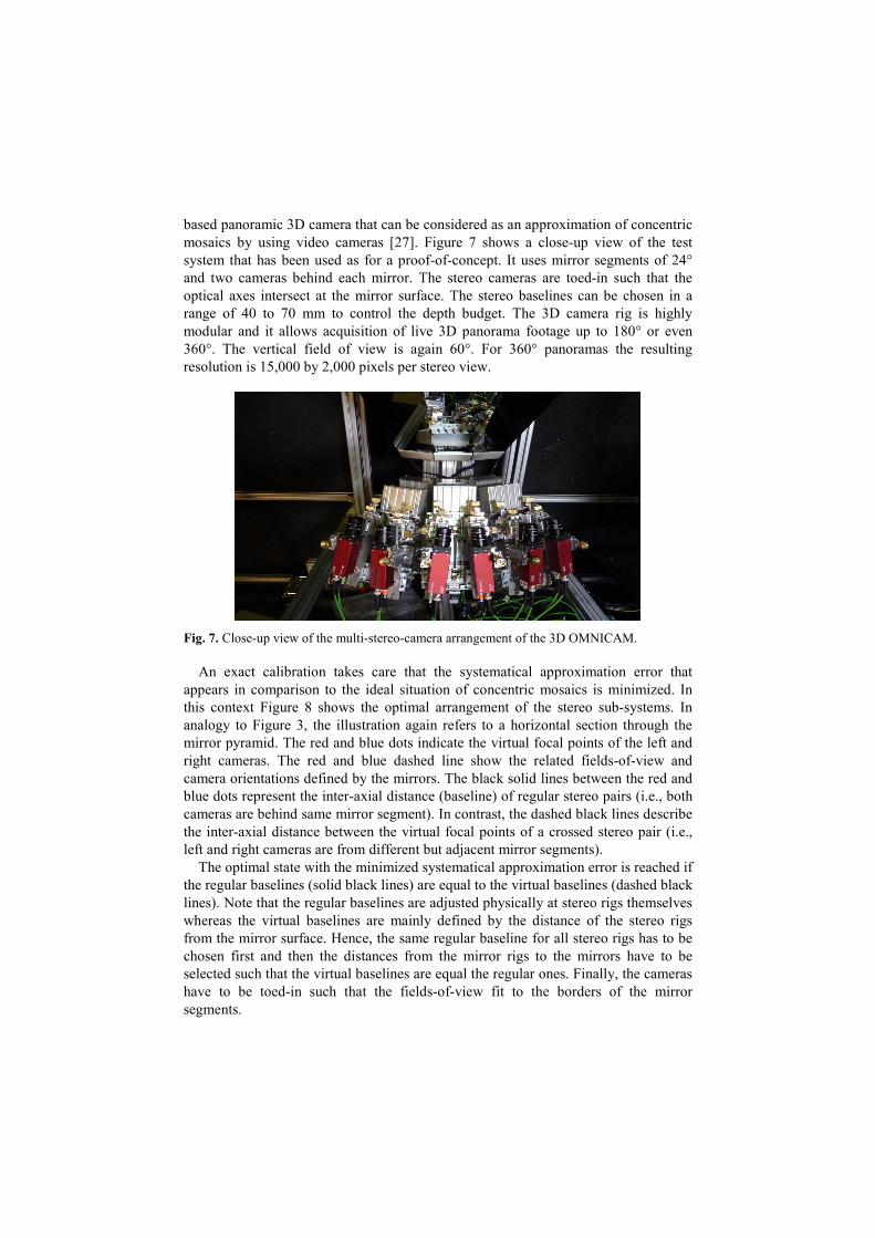
based panoramic 3D camera that can be considered as an approximation of concentric mosaics by using video cameras [27]. Figure 7 shows a close-up view of the test system that has been used as for a proof-of-concept. It uses mirror segments of 24° and two cameras behind each mirror. The stereo cameras are toed-in such that the optical axes intersect at the mirror surface. The stereo baselines can be chosen in a range of 40 to 70 mm to control the depth budget. The 3D camera rig is highly modular and it allows acquisition of live 3D panorama footage up to 180° or even 360°. The vertical field of view is again 60°. For 360° panoramas the resulting resolution is 15,000 by 2,000 pixels per stereo view.
Fig. 7. Close-up view of the multi-stereo-camera arrangement of the 3D OMNICAM.
An exact calibration takes care that the systematical approximation error that appears in comparison to the ideal situation of concentric mosaics is minimized. In this context Figure 8 shows the optimal arrangement of the stereo sub-systems. In analogy to Figure 3, the illustration again refers to a horizontal section through the mirror pyramid. The red and blue dots indicate the virtual focal points of the left and right cameras. The red and blue dashed line show the related fields-of-view and camera orientations defined by the mirrors. The black solid lines between the red and blue dots represent the inter-axial distance (baseline) of regular stereo pairs (i.e., both cameras are behind same mirror segment). In contrast, the dashed black lines describe the inter-axial distance between the virtual focal points of a crossed stereo pair (i.e., left and right cameras are from different but adjacent mirror segments).
The optimal state with the minimized systematical approximation error is reached if the regular baselines (solid black lines) are equal to the virtual baselines (dashed black lines). Note that the regular baselines are adjusted physically at stereo rigs themselves whereas the virtual baselines are mainly defined by the distance of the stereo rigs from the mirror surface. Hence, the same regular baseline for all stereo rigs has to be chosen first and then the distances from the mirror rigs to the mirrors have to be selected such that the virtual baselines are equal the regular ones. Finally, the cameras have to be toed-in such that the fields-of-view fit to the borders of the mirror segments.
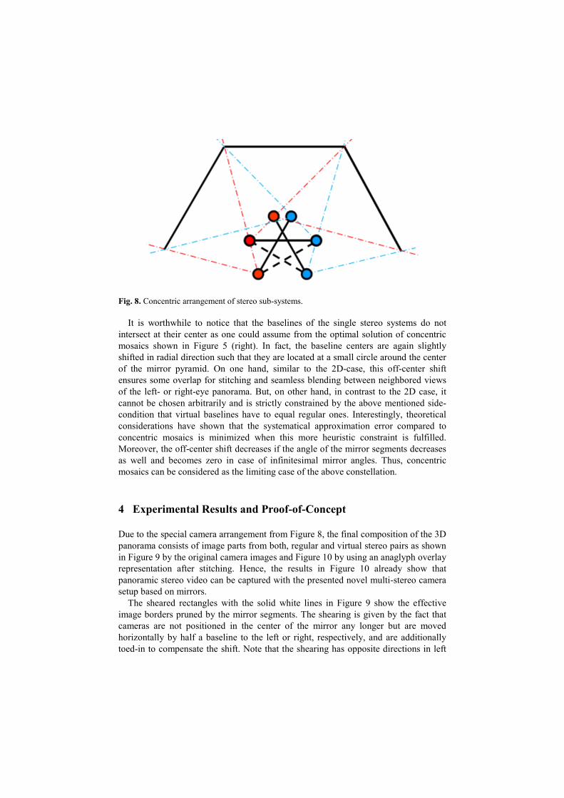
Fig. 8. Concentric arrangement of stereo sub-systems.
It is worthwhile to notice that the baselines of the single stereo systems do not intersect at their center as one could assume from the optimal solution of concentric mosaics shown in Figure 5 (right). In fact, the baseline centers are again slightly shifted in radial direction such that they are located at a small circle around the center of the mirror pyramid. On one hand, similar to the 2D-case, this off-center shift ensures some overlap for stitching and seamless blending between neighbored views of the left- or right-eye panorama. But, on other hand, in contrast to the 2D case, it cannot be chosen arbitrarily and is strictly constrained by the above mentioned side-condition that virtual baselines have to equal regular ones. Interestingly, theoretical considerations have shown that the systematical approximation error compared to concentric mosaics is minimized when this more heuristic constraint is fulfilled. Moreover, the off-center shift decreases if the angle of the mirror segments decreases as well and becomes zero in case of infinitesimal mirror angles. Thus, concentric mosaics can be considered as the limiting case of the above constellation.
4 Experimental Results and Proof-of-Concept
Due to the special camera arrangement from Figure 8, the final composition of the 3D panorama consists of image parts from both, regular and virtual stereo pairs as shown in Figure 9 by the original camera images and Figure 10 by using an anaglyph overlay representation after stitching. Hence, the results in Figure 10 already show that panoramic stereo video can be captured with the presented novel multi-stereo camera setup based on mirrors.
The sheared rectangles with the solid white lines in Figure 9 show the effective image borders pruned by the mirror segments. The shearing is given by the fact that cameras are not positioned in the center of the mirror any longer but are moved horizontally by half a baseline to the left or right, respectively, and are additionally toed-in to compensate the shift. Note that the shearing has opposite directions in left
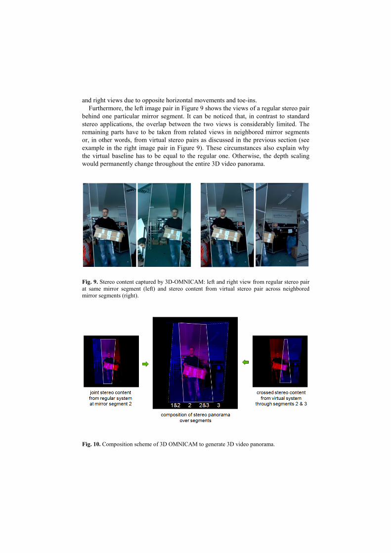
and right views due to opposite horizontal movements and toe-ins. Furthermore, the left image pair in Figure 9 shows the views of a regular stereo pair
behind one particular mirror segment. It can be noticed that, in contrast to standard stereo applications, the overlap between the two views is considerably limited. The remaining parts have to be taken from related views in neighbored mirror segments or, in other words, from virtual stereo pairs as discussed in the previous section (see example in the right image pair in Figure 9). These circumstances also explain why the virtual baseline has to be equal to the regular one. Otherwise, the depth scaling would permanently change throughout the entire 3D video panorama.
Fig. 9. Stereo content captured by 3D-OMNICAM: left and right view from regular stereo pair at same mirror segment (left) and stereo content from virtual stereo pair across neighbored mirror segments (right).
Fig. 10. Composition scheme of 3D OMNICAM to generate 3D video panorama.
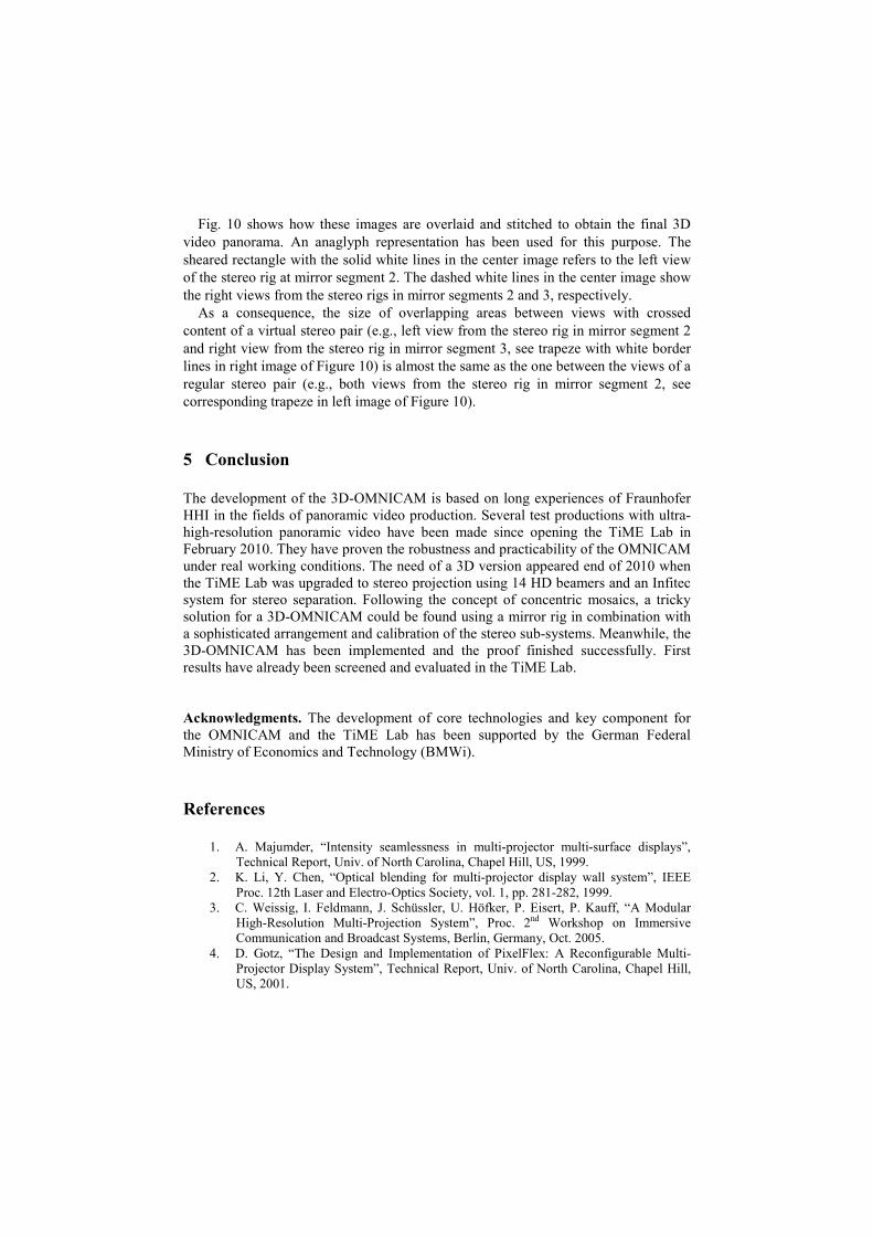
Fig. 10 shows how these images are overlaid and stitched to obtain the final 3D video panorama. An anaglyph representation has been used for this purpose. The sheared rectangle with the solid white lines in the center image refers to the left view of the stereo rig at mirror segment 2. The dashed white lines in the center image show the right views from the stereo rigs in mirror segments 2 and 3, respectively.
As a consequence, the size of overlapping areas between views with crossed content of a virtual stereo pair (e.g., left view from the stereo rig in mirror segment 2 and right view from the stereo rig in mirror segment 3, see trapeze with white border lines in right image of Figure 10) is almost the same as the one between the views of a regular stereo pair (e.g., both views from the stereo rig in mirror segment 2, see corresponding trapeze in left image of Figure 10).
5 Conclusion
The development of the 3D-OMNICAM is based on long experiences of Fraunhofer HHI in the fields of panoramic video production. Several test productions with ultra-high-resolution panoramic video have been made since opening the TiME Lab in February 2010. They have proven the robustness and practicability of the OMNICAM under real working conditions. The need of a 3D version appeared end of 2010 when the TiME Lab was upgraded to stereo projection using 14 HD beamers and an Infitec system for stereo separation. Following the concept of concentric mosaics, a tricky solution for a 3D-OMNICAM could be found using a mirror rig in combination with a sophisticated arrangement and calibration of the stereo sub-systems. Meanwhile, the 3D-OMNICAM has been implemented and the proof finished successfully. First results have already been screened and evaluated in the TiME Lab.
Acknowledgments. The development of core technologies and key component for the OMNICAM and the TiME Lab has been supported by the German Federal Ministry of Economics and Technology (BMWi).
References
1. A. Majumder, “Intensity seamlessness in multi-projector multi-surface displays”, Technical Report, Univ. of North Carolina, Chapel Hill, US, 1999.
2. K. Li, Y. Chen, “Optical blending for multi-projector display wall system”, IEEE Proc. 12th Laser and Electro-Optics Society, vol. 1, pp. 281-282, 1999.
3. C. Weissig, I. Feldmann, J. Schüssler, U. Höfker, P. Eisert, P. Kauff, “A Modular High-Resolution Multi-Projection System”, Proc. 2nd Workshop on Immersive Communication and Broadcast Systems, Berlin, Germany, Oct. 2005.
4. D. Gotz, “The Design and Implementation of PixelFlex: A Reconfigurable Multi-Projector Display System”, Technical Report, Univ. of North Carolina, Chapel Hill, US, 2001.
5. O. Bimber, “Multi-Projector Techniques for Real-Time Visualizations in Everyday Environments”, Proc. IEEE Virtual Reality Conference, Workshop on Emerging Display Technologies, 2006.
6. E. Lantz, „A Survey of Large-Scale Immersive Displays”, Proc. Emerging Display Technology Conference, ACM SIGGRAPH, 2007.
7. Fraunhofer IFF, “The Elbe Dome: Immerse in Virtual Worlds”, VDTC 2011, www.vdtc.de/allg/elbe-dom-eng-fraunhofer-iff.pdf
8. HPC Market Watch, “Seattle Cinerama Grand Reopening, 2011, http://markets.hpcwire.com/taborcomm.hpcwire/news/read?GUID=15456683&ChannelID=3197
9. Fraunhofer HHI, “Official Opening of the HHI TiME Lab”, Symposium Tomorrow's Cinema – The Future of Content, February 2010, www.hhi.fraunhofer.de/en/events/trade-fairs-and-events-archive/official-opening-of-the-hhi-time-lab/time_ov/official-opening-of-the-hhi-time-lab/
10. U. Iwerks, “Panoramic Motion Picture Camera Arrangement”, Canadian Patent Publication, no. CA 673633, 1963.
11. A. Majumder, M. Gopi, B. Seales, H. Fuchs, “Immersive teleconferencing: A new algorithm to generate seamless panoramic video imagery”, Proc. of the 7th ACM International Conference on Multimedia, pp. 169–178, 1999.
12. D. W. Rees, “Panoramic television viewing system”, United States Patent No. 3, 505, 465, Apr. 1970.
13. S. Baker, S. Nayar, “A theory of single-viewpoint catadioptric image formation” Int. Journal of Computer Vision, 35:175–196, 1999.
14. MegaVision, “The Mega Vision System Overview”, October 2004, http://www.megavision.co.jp/eng/solution/index.html
15. Point Grey, “Spherical Vision”, http://www.ptgrey.com 16. Carmagus, “Endzone”, www.camargus.com/maxx-zoom.html 17. Journal Sentinel, “ESPN offers a closer view with Maxx Zoom technology”,
www.jsonline.com/sports/103677489.html 18. Immersive Media, “Dodeca 2360 Camera System”, www.immersivemedia.com/
products/capture.shtml 19. Full View, “FC-1005 Camera & FC-110 Camera”, www.fullview.com/products.html 20. Remote Reality, “OmniAlert360”, www.remotereality.com/omnialert360-
productsmenu-121 21. iMovie Inc, “GeoView-3000-LB3”, www.imoveinc.com/geoview.php 22. P. Sturm, S. Ramalingam, J.-P. Tardif, S. Gasparini, J. Barreto, “Camera Models and
Fundamental Concepts Used in Geometric Computer Vision”, Foundations and Trends in Computer Graphics and Vision, vol. 6, no 1–2, pp. 1-183, 2010.
23. K. A. Tan, H. Hua, N. Ahuja, “Multiview Panoramic Cameras Using Mirror Pyramids”, Trans. on Pattern Analysis and Machine Intelligence, Vol. 26, no7, pp.941-946, 2004.
24. S. Peleg, M. Ben-Ezra, Y. Pritch, "Omnistereo: panoramic stereo imaging", IEEE Transactions on Pattern Analysis and Machine Intelligence, Vol.23, No.3, pp.279-290, March 2001.
25. H.-Y. Shum, L.-W. He, “Rendering with Concentric Mosaics”, Proc. SIGGRAPH 99, ACM, Los Angeles 99.
26. J-H. Chai, X. Tong, S.-C. Chan, H.-Y. Shum, “Plenoptic Sampling”, Proc. SIGGRAPH 99, ACM, New Orleans 2000.
27. H.-J. Schüssler, C. Weissig, P. Kauff, P. Eisert, “3D OmniCam”, US Provisional Application, No. 61/473595, April 2011.


![MASTER REPORT REVIEW OF GENERAL PANORAMIC OPTICAL … · and security, panoramic endoscope, machine vision, panoramic projection system, and so on [1, 2]. Panoramic lens systems can](https://img.dokumen.tips/doc/110x75/5e184f54abc03831285efb0b/master-report-review-of-general-panoramic-optical-and-security-panoramic-endoscope.jpg)