Embed Size (px)
Citation preview

The tile assembly model is intrinsically universal
David Doty∗ Jack H. Lutz† Matthew J. Patitz‡ Robert T. Schweller§
Scott M. Summers¶ Damien Woods‖
Abstract
We prove that the abstract Tile Assembly Model (aTAM) of nanoscale self-assembly isintrinsically universal. This means that there is a single tile assembly system U that, withproper initialization, simulates any tile assembly system T . The simulation is “intrinsic” in thesense that the self-assembly process carried out by U is exactly that carried out by T , with eachtile of T represented by an m×m “supertile” of U . Our construction works for the full aTAMat any temperature, and it faithfully simulates the deterministic or nondeterministic behaviorof each T .
Our construction succeeds by solving an analog of the cell differentiation problem in devel-opmental biology: Each supertile of U , starting with those in the seed assembly, carries the“genome” of the simulated system T . At each location of a potential supertile in the self-assembly of U , a decision is made whether and how to express this genome, i.e., whether togenerate a supertile and, if so, which tile of T it will represent. This decision must be achievedusing asynchronous communication under incomplete information, but it achieves the correctglobal outcome(s).
∗Computing and Mathematical Sciences, California Institute of Technology, Pasadena, CA 91125, [email protected]. This author’s research was supported by a Computing Innovation Fellowship under NSF grant1019343.†Computer Science, Iowa State University, Ames, IA 50011 USA. [email protected]. This author’s research was
supported by NSF grants 0652569 and 1143830. Part of this work was done during a sabbatical at Caltech and theIsaac Newton Institute for Mathematical Sciences at the University of Cambridge.‡Computer Science, University of Texas–Pan American, Edinburg, TX, 78539, USA. [email protected]. This
author’s research was supported in part by NSF grant CCF-1117672.§Computer Science, University of Texas–Pan American, Edinburg, TX, 78539, USA. [email protected].
This author’s research was supported in part by NSF grant CCF-1117672.¶Computer Science and Software Engineering, University of Wisconsin–Platteville, Platteville, WI 53818, USA.
[email protected].‖Computer Science, California Institute of Technology, Pasadena, CA 91125, USA. [email protected]. This
author’s research was supported by NSF grant 0832824, the Molecular Programming Project.
arX
iv:1
111.
3097
v2 [
cs.D
S] 7
Apr
201
2
1 Introduction
Structural DNA nanotechnology, pioneered by Seeman in the 1980s [44], exploits the information-processing capabilities of nucleic acids to engineer complex structures and devices at the nanoscale.This is a very “hands-off” sort of engineering: The right molecules are placed in solution, and thestructures and devices self-assemble spontaneously according to the principles of chemical kinetics.Controlling such self-assembly processes is an enormous technical challenge, but impressive progresshas already been made. Regular arrays [49], polyhedra [27], fractal structures [25, 42], maps ofthe world [43], curved three-dimensional vases [26], DNA tweezers [50], logic circuits [38], neuralnetworks [39], and molecular robots [34] are a few of the nanoscale objects that have self-assembledin successful laboratory experiments. Motivating future applications include smaller, faster, moreenergy-efficient computer chips, single-molecule detection, and in-cell diagnosis and treatment ofdisease.
Theoretical computer science became involved with structural DNA nanotechnology just beforethe turn of this century. In his 1998 Ph.D. thesis, Winfree introduced a mathematical model ofDNA tile self-assembly and proved that this model is Turing-universal, i.e., that it can simulateany Turing machine [48]. This implies that nanoscale self-assembly can be algorithmically directed,and that extremely complex structures and devices can in principle be engineered by self-assembly.Rothemund and Winfree [41] subsequently refined this model slightly, formulating the abstract TileAssembly Model (aTAM). The (two-dimensional) aTAM is an idealized model of error-free self-assembly in two dimensions that has been extensively investigated [1–8,12–15,18–20,23,28, 29, 35,45,46] and is the subject of this paper.
Very briefly, a tile in the aTAM is a unit square with a kind and strength of “glue” on eachof its sides. A tile assembly system T consists of a finite collection T of tile types (with infinitelymany tiles of each type in T available), a seed assembly σ consisting of one or more tiles of typesin T , and a temperature τ . Self-assembly proceeds from the seed assembly σ, with tiles of typesin T successively and nondeterministically attaching themselves to the existing assembly. Two tilesplaced next to each other interact if the glues on their abutting sides match, and a tile binds toan assembly if the total strength on all of its interacting sides is at least τ . A more completedescription of the aTAM appears in Section 2.
Our topic is the intrinsic universality of the abstract Tile Assembly Model. We now explainwhat this means, starting with what it does not mean. By Winfree’s above-mentioned result, thereis a tile assembly system U that simulates a universal Turing machine. This universal Turingmachine, and hence U , can simulate any tile assembly system T (in fact, there are various aTAMsoftware simulators available, e.g., [37]). But this is only a computational simulation. It tells uswhat T does, but it does not actually do what T does. The task of a Turing machine is to performa computation, and a universal Turing machine performs the same computation as a machine thatit simulates. The task of a tile assembly system is to perform the process of self-assembly, so auniversal tile assembly system should perform the same self-assembly process as a tile assemblysystem that it simulates. This is what is meant by intrinsic universality.
This paper proves that the abstract Tile Assembly Model is intrinsically universal.This means that there is a single tile set U that, with proper initialization (calling the initialized
system U), simulates any tile assembly system T . The simulation is “intrinsic” in the sense thatthe self-assembly process carried out by U is exactly that carried out by T , with each tile ofT represented by an m × m “supertile” of U . Our construction works for the full aTAM atany temperature (the simulating system U uses temperature 2), and it faithfully simulates the
1

deterministic or nondeterministic behavior of each T . This notion was studied by Ollinger [36] andothers [11,16,24,30–32] in the context of cellular automata and Wang tiling,
Our construction succeeds by solving an analog of the cell differentiation problem in develop-mental biology: Each supertile of U , starting with those in the seed assembly, carries a completeencoding of the simulated system T (the “genome” of T ) along each of its sides, which we call“supersides”. (This genome accounts for most of the m tiles of U that appear on each superside.Additional tiles along the superside identify the glue of the simulated tile of T and support a va-riety of communication mechanisms.) At each location of a potential supertile a decision is madewhether and how to express this genome, i.e., whether to generate a supertile and, if so, whichtile of T it will represent. (This latter choice will be nondeterministic precisely insofar as T isnondeterministic at this location.) This decision depends on very limited local information, but itachieves the correct global outcome(s). The self-assembly of U is thus a “developmental process” inwhich “supertile differentiation” is governed by local communication, while the “genome” is passedintact from supertile to supertile.
Our construction uses three basic interacting primitives to carry out the asynchronous communi-cation under imperfect information needed for supertile differentiation and genome copying. Thesemechanisms are called frames, crawlers, and probes. The frame of a potential supertile consists offour layers of tiles just inside each extant superside. This frame is used for communication withadjacent supersides, which may or may not exist. Much of its function is achieved by a symmetry-breaking “competition” at each corner. Our construction uses many types of crawlers, which aremessengers that copy and carry various pieces of information from place to place in the supertile.The probes of a superside are used to communicate with the opposite superside, which may or maynot exist. The challenge is to program all this activity without ever blocking a path that may laterbe needed for intra-supertile communication. This summary is greatly oversimplified. An overviewof our construction is presented in Section 4, and the full construction is presented in Sections 5–10.We have used various symmetries to simplify the construction and its presentation, and we hopethat the sheer number of cases does not obscure the underlying elegance of the machinery.
Our result shows that the aTAM is universal for itself, without recourse to indirect simulationsby Turing machines or other models that obscure important properties of the model. For example,our result shows that the tile assembly model is able to simulate local interactions between tiles,nondeterminism, and tile growth processes in general, all on a global scale. Thus our intrinsicallyuniversal tile set captures, in a well defined way, all properties of any tile assembly system.
Intrinsic universality, with its precise notion of “simulate”, has applications to the theory ofself-assembly. Firstly, a useful type of simulation is where one shows that for all aTAM systems Tthere exists a tile assembly system T ′ in some other self-assembly model that simulates T . Thisstyle of ∀ T ,∃ T ′-simulation has been used previously [5, 9, 17] and is useful when comparing thepower of tile assembly models. However, combining such a simulation statement with the statementof our main result gives the immediate corollary that there is a single set of tiles U in the othermodel that, when appropriately seeded, simulates any aTAM tile assembly system T . Hence ourmain result automatically shows the existence of a single, very powerful, tile set in the other model,a seemingly strong statement. Secondly, and more speculatively, our result opens the possibilityfor new research directions in self-assembly. For example, taken together with the result in [22],we now know of two classes of tile assembly systems that exhibit intrinsic universality: the fullaTAM (our main result), and the more restricted locally consistent systems [22]. This gives a kindof closure property for these classes of systems. In the field of cellular automata, the notion of
2

intrinsic universality has led to the development of formal tools to classify models of computationin terms of their ability to simulate each other [16]. The intrinsically universal cellular automatasit at the top of this “quasi-order”. As an example of a concrete application of this work, thenotion of intrinsic universality has been used [10, 11] to show that various elementary cellularautomata are strictly less powerful than others. Specifically, it was shown that the communicationcomplexity of those systems is too low for them to exhibit intrinsic universality, and so there is awide range of behaviors they can never achieve. Such statements crucially make use of the factthat intrinsic universality uses a tight notion of “simulate”. In tile self-assembly, we currently havevery few tools by which to compare the abilities of models; the main comparisons essentially boildown to comparing tile complexity, or establishing whether or not the system can simulate Turingmachines and thus make arbitrary computable shapes. Both comparisons, especially the latter, arenecessarily rather coarse for comparing the expressibility of models, and we hope that our result,and the notion of “simulate” that we use, can inspire the development of work that elucidates afine-grained structure for self-assembly.
We conclude this introduction with a brief discussion of related work. The most recent precur-sor is [22], in which some of the present authors showed that a restricted submodel of the aTAM isintrinsically universal. This was an extensive, computationally expressive submodel of the aTAM,but its provisos (temperature 2, no glue mismatches, and no binding strengths exceeding the tem-perature) were artificially restrictive, awkward to justify on molecular grounds, and inescapablefrom the standpoint of that paper’s proof technique. Our approach here is perforce completelydifferent. Both papers code the simulated system’s genome along the supersides, but the resem-blance ends there. The frames, crawlers, and probes that we use here are new. (The “probe-like”structures in [22] are too primitive to work for simulating the full aTAM.)
As noted in [22], constructions of Soloveichik and Winfree [45] and Demaine, Demaine, Fekete,Ishaque, Rafalin, Schweller, and Souvaine [18] can be used to achieve versions of intrinsic univer-sality for tile assembly at temperature 1, but this appears to be a severe restriction. Additionally,the latter paper uses a generalized version of the aTAM (i.e., “hierarchical” self-assembly or the“two-handed” aTAM) that has a mechanism for long-range communication that is lacking in thestandard aTAM and that obviates the need for the distributed communication mechanisms weemploy to build supertiles. Also discussed in [22] are studies of universality in Wang tiling [47]such as those by Lafitte and Weiss [30–32]. While these studies are very significant in the contextsof mathematical logic and computability theory, they are concerned with the existence of tilingswith no mismatches, and not with any process of self-assembly. In particular, most attempts toadapt the constructions of Wang tiling studies (such as those in [30–32]) to self-assembly result ina tile assembly system in which many junk assemblies are formed due to incorrect nondeterministicchoices being made that arrest any further growth and/or result in assemblies that are inconsistentwith the desired output assembly. We therefore require novel techniques to ensure that the onlyproduced assemblies are those that represent the intended result or valid partial progress toward it.Furthermore, techniques used in constructing intrinsically universal cellular automata do not carryover to the aTAM as the models have fundamental differences; in particular, when a tile is placed itremains in-place forever, whereas cellular automata cells can be reused indefinitely. In fact, manyof the challenging issues in proving our result are related to the fact that tiles, once placed, canblock each other and, of course, that self-assembly is a highly asynchronous and nondeterministicprocess.
3

2 Abstract Tile Assembly Model
This section gives a brief informal sketch of the abstract Tile Assembly Model (aTAM). See Sec-tion A for a formal definition of the aTAM.
A tile type is a unit square with four sides, each consisting of a glue label (often representedas a finite string) and a nonnegative integer strength. We assume a finite set T of tile types, butan infinite number of copies of each tile type, each copy referred to as a tile. An assembly (a.k.a.,supertile) is a positioning of tiles on the integer lattice Z2; i.e., a partial function α : Z2 99K T . LetAT denote the set of all assemblies of tiles from T , and let AT<∞ denote the set of finite assemblies oftiles from T . Write α v β to denote that α is a subassembly of β, which means that dom α ⊆ dom βand α(p) = β(p) for all points p ∈ dom α. Two adjacent tiles in an assembly interact if the gluelabels on their abutting sides are equal and have positive strength. Each assembly induces a bindinggraph, a grid graph whose vertices are tiles, with an edge between two tiles if they interact. Theassembly is τ -stable if every cut of its binding graph has strength at least τ , where the weight ofan edge is the strength of the glue it represents. That is, the assembly is stable if at least energyτ is required to separate the assembly into two parts.
A tile assembly system (TAS) is a triple T = (T, σ, τ), where T is a finite set of tile types,σ : Z2 99K T is a finite, τ -stable seed assembly, and τ is the temperature. An assembly α isproducible if either α = σ or if β is a producible assembly and α can be obtained from β by thestable binding of a single tile. In this case write β →T1 α (α is producible from β by the attachmentof one tile), and write β →T α if β →T ∗1 α (α is producible from β by the attachment of zeroor more tiles). When T is clear from context, we may write →1 and → instead. An assembly isterminal if no tile can be τ -stably attached to it. Let A[T ] be the set of producible assemblies ofT , and let A[T ] ⊆ A[T ] be the set of producible, terminal assemblies of T . A TAS T is directed(a.k.a., deterministic, confluent) if |A[T ]| = 1.
We make the following assumptions that do not affect the fundamental capabilities of themodel, but which will simplify our main construction. Since the behavior of a TAS T = (T, σ, τ)is unchanged if every glue with strength greater than τ is changed to have strength exactly τ , weassume henceforth that all glue strengths are in the set 0, 1, . . . , τ. We assume that glue labelsare never shared between glues of unequal strength.
3 Main result
To state our main result, we must formally define what it means for one TAS to “simulate” another.We focus in particular on a sort of “direct simulation” via block replacement (m×m blocks of tilesin the simulating system represent single tiles in the simulated system). The intuitive goal of thefollowing definition is identical to that in [22], and corrects some subtle errors there.
Let m ∈ Z+. An m-block supertile over tile set T is a partial function α : Zm × Zm 99K T ,where Zm = 0, 1, . . . ,m − 1. Let BT
m be the set of all m-block supertiles over T . The m-blockwith no domain is said to be empty. For a general assembly α : Z2 99K T and x, y ∈ Z, define αmx,yto be the m-block supertile defined by αmx,y(i, j) = α(mx + i,my + j) for 0 ≤ i, j < m. A partial
function R : BSm 99K T is said to be a valid m-block supertile representation from S to T if for any
α, β ∈ BSm such that α v β and α ∈ dom R, then R(α) = R(β).
For a given valid m-block supertile representation function R from tile set S to tile set T ,define the assembly representation function R∗ : AS → AT such that R∗(α′) = α if and only if
4

α(x, y) = R(α′mx,y) for all x, y ∈ Z.1 For an assembly α′ ∈ AS such that R(α′) = α, α′ is said to
map cleanly to α ∈ AT under R∗ if for all non empty blocks α′mx,y, (x+ u, y + v) ∈ dom α for someu, v ∈ −1, 0, 1, or if α′ has at most one non-empty m-block αm0,0. In other words, α′ may havetiles on supertile blocks representing empty space in α, but only if that position is adjacent to atile in α.
A TAS S = (S, σS , τS) simulates a TAS T = (T, σT , τT ) at scale m ∈ Z+ if there exists anm-block representation R : BS
m → T such that the following hold:
1. Equivalent Production.
(a) R∗(α′)|α′ ∈ A[S] = A[T ].
(b) For all α′ ∈ A[S], α′ maps cleanly to R∗(α′).
2. Equivalent Dynamics.
(a) If α→T β for some α, β ∈ A[T ], then for all α′ such that R∗(α′) = α, α′ →S β′ for someβ′ ∈ A[S] with R∗(β′) = β.
(b) If α′ →S β′ for some α′, β′ ∈ A[S], then R∗(α′)→T R∗(β′).
Let REPR denote the set of all supertile representation functions (i.e., m-block supertile repre-sentation functions for some m ∈ Z+). Let C be a class of tile assembly systems, and let U be a tileset.2 Note that every element of C, REPR, and AU<∞ is a finite object, hence can be representedin a suitable format for computation in some formal system such as Turing machines. We say Uis intrinsically universal for C if there are computable functions R : C→ REPR and S : C→ AU<∞and τ ′ ∈ Z+ such that, for each T = (T, σ, τ) ∈ C, there is a constant m ∈ N such that, lettingR = R(T ), σT = S(T ), and UT = (U, σT , τ
′), UT simulates T at scale m and using supertile rep-resentation function R. That is, R(T ) outputs a representation function that interprets assembliesof UT as assemblies of T , and S(T ) outputs the seed assembly used to program tiles from U torepresent the seed assembly of T .
Our main theorem states that there is a single tile set capable of simulating any tile assemblysystem.
Theorem 3.1. There is a tile set U that is intrinsically universal for the class of all tile assemblysystems.
The rest of the paper is devoted to describing the construction of U and justifying its correctness.Throughout this paper, T = (T, σ, τ) will denote an arbitrary TAS being simulated. Let g ∈ Z+
denote the number of different glues in T ; note that g = O(|T |). In our main construction, weachieve scale factor m = O(g4 log g); an interesting open question is decreasing this scale factor orproving a nontrivial lower bound on it.
1Note that R∗ is a total function since every assembly of S represents some assembly of T ; the other functionssuch as R and α are partial to allow undefined points to represent empty space.
2TAS’s having tile set U are not necessarily elements of C, although this will be true in our main theorem since Cwill be the set of all TAS’s.
5

4 High-level description of construction
In this section we sketch an intuitive overview of the construction. The full construction, includingdetailed figures, is contained in Sections 5–10, in the Technical Appendix. Let T = (T, σ, τ) be aTAS being simulated by U = (U, σT , 2), where U is the universal tile set and σT is the appropriateseed assembly for U to simulate T . The seed assembly σT encodes information about the gluesfrom T that are on the perimeter of σ, with each exposed tile-side of σ encoded as a “superside” asshown in Figure 2. In particular, glues are simply encoded as binary strings of length O(log |T |).(Glue strengths are not explicitly encoded since their effect on binding is implicitly accounted for byother parts of the design.) Most importantly, each of these supersides, as well as each superside ofall subsequently grown supertiles, encodes information about the entire TAS T . This informationis like the “genome” of the system that is transported to each supertile of the assembly in order tohelp direct its growth based on the contents of T .
4.1 The fundamental problem of simulating arbitrary tile systems
The basic problem faced by any superside adjacent to an empty supertile is this: the supersidemust determine what other superside(s) are adjacent to the same empty supertile, what glue(s) areon those sides, whether those glues are part of a tile type t ∈ T and whether they have enoughstrength to bind t (and to choose among multiple tile types if more than one match the glues),and if so, the supersides on the remaining sides of t must be constructed (i.e., placed as “output”on empty supersides). This must be done in concert with other supersides that will be attemptingthe same thing, possibly “unaware” of each others’ presence, and it must be done without priorknowledge of which other supersides will eventually arrive and the order and timing of their arrival.
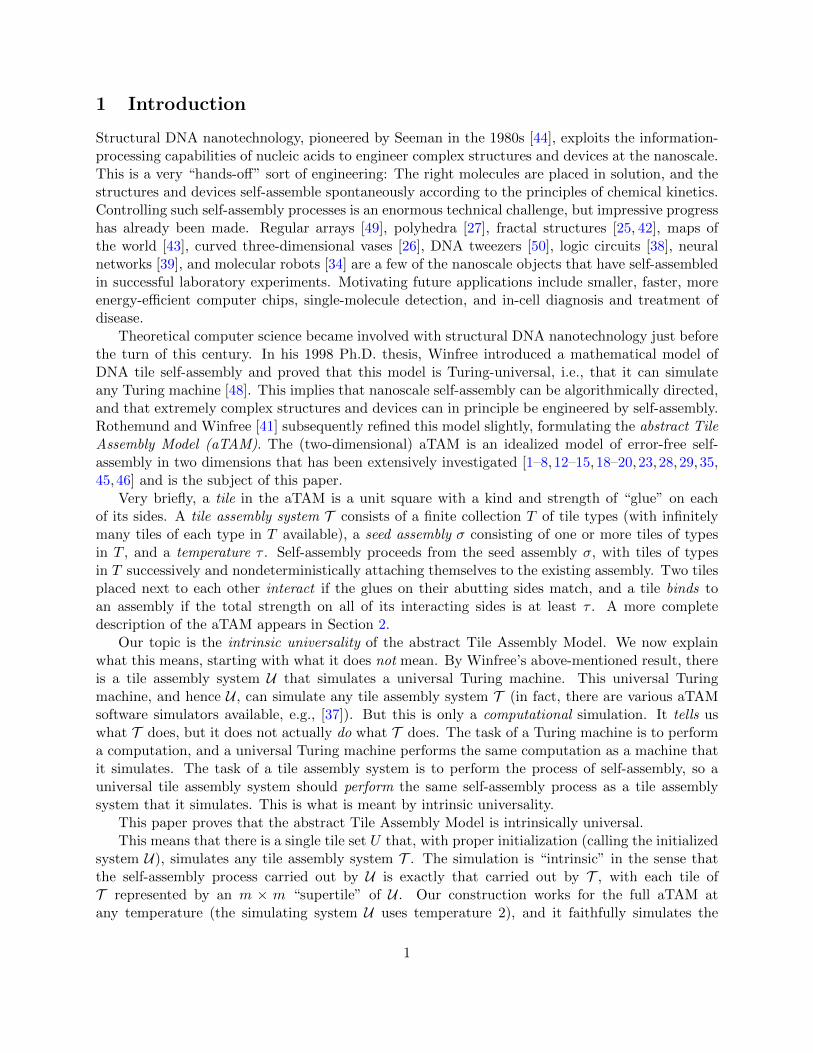
To illustrate the nontriviality of this problem, consider the following scenario illustrated inFigure 1a. Two supertiles arrive at positions that are north and south of an empty supertileposition, with the east and west positions being unoccupied. The south superside has no choicebut to attempt to “contact” the north superside, for it may be the case that their glues match thatof some tile type t ∈ T , in which case the west and east supersides representing the sides of t mustbe put in place. But suppose that although there is a north superside, the glue it represents is notshared with the south glue on any tile type in T , or perhaps their combined strength is less than τ .(See Figure 1a.) Intuitively, it seems that to determine this, the north and south supersides mustconnect, in order to bring their glues together and do a computation/lookup to find that no tiletype in T shares them. But once they have connected, the west and east sides of the supertile arenow sealed off from each other.
Suppose that at a later time, a superside arrives on the west, and its encoded glue is sharedwith the west glue on some tile type t ∈ T (with a north glue mismatching that of the supertilealready present there; see Figure 1b). This means that t’s east glue must now be represented byconstructing an east output superside; however, this information cannot be communicated from thewest side of the supertile because the previous attempt to connect the south and north has createda barrier between east and west.
Note that such problems do not appear in Wang tiling constructions where nondeterminismcould be used to simply guess what the other sides are.
This is not the only potential pitfall to be faced, but it illustrates one difficulty of coordinatinginteraction between multiple supersides in the absence of knowledge about which supersides will
6
S
S
N
N N
?
?
?
?
(a) The north side got to talk with the south side, and theconsensus is that there is no tile whose north side is ‘N’ andwhose south side is ’S’. Better luck next time!
S
S
N
N
EW
W
?
? ?
?
WE
W
S
(b) Uh oh! There seems to be no way to“communicate” from the west side to the eastthat the ‘WE’ tile should be represented here.
Figure 1: How should supertiles communicate across a gap without “cutting the supertile in two”?
eventually arrive, the order in which they will arrive, and what glues they will represent.3
4.2 Basic protocol
Here we give a high-level overview of our construction.
4.2.1 Frame
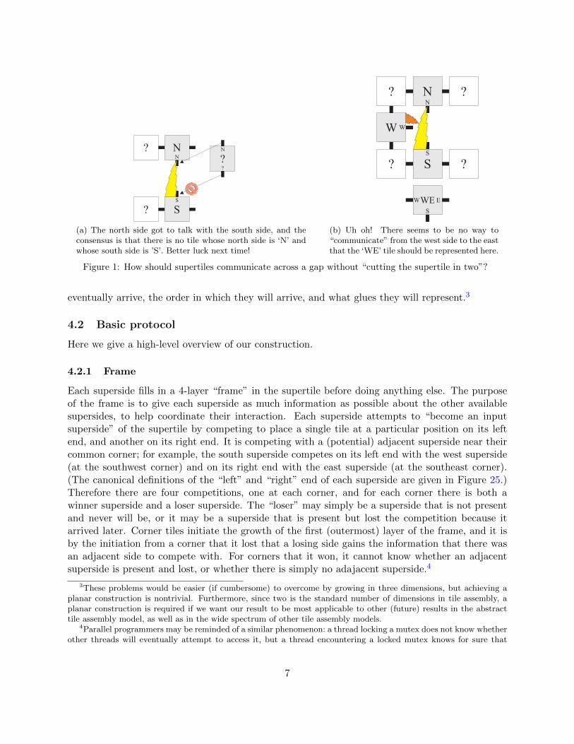
Each superside fills in a 4-layer “frame” in the supertile before doing anything else. The purposeof the frame is to give each superside as much information as possible about the other availablesupersides, to help coordinate their interaction. Each superside attempts to “become an inputsuperside” of the supertile by competing to place a single tile at a particular position on its leftend, and another on its right end. It is competing with a (potential) adjacent superside near theircommon corner; for example, the south superside competes on its left end with the west superside(at the southwest corner) and on its right end with the east superside (at the southeast corner).(The canonical definitions of the “left” and “right” end of each superside are given in Figure 25.)Therefore there are four competitions, one at each corner, and for each corner there is both awinner superside and a loser superside. The “loser” may simply be a superside that is not presentand never will be, or it may be a superside that is present but lost the competition because itarrived later. Corner tiles initiate the growth of the first (outermost) layer of the frame, and it isby the initiation from a corner that it lost that a losing side gains the information that there wasan adjacent side to compete with. For corners that it won, it cannot know whether an adjacentsuperside is present and lost, or whether there is simply no adajacent superside.4
3These problems would be easier (if cumbersome) to overcome by growing in three dimensions, but achieving aplanar construction is nontrivial. Furthermore, since two is the standard number of dimensions in tile assembly, aplanar construction is required if we want our result to be most applicable to other (future) results in the abstracttile assembly model, as well as in the wide spectrum of other tile assembly models.
4Parallel programmers may be reminded of a similar phenomenon: a thread locking a mutex does not know whetherother threads will eventually attempt to access it, but a thread encountering a locked mutex knows for sure that
7

The first layer of the frame grows from the corners of the superside to its center, at whichpoint the entire superside knows whether it won or lost each corner. The subsequent layers of theframe allow the pattern of wins and losses for each side to be propagated among adjacent sides ina well defined way. The careful design of the frame and the algorithm for passing this informationallows the large set of possible scenarios (of all subsets of sides which may be present in all possibleorderings) to be condensed into a much smaller set of equivalent classes of scenarios which can thenbe properly handled by the next portions of the supertile to grow (as necessary) from the frame:“crawlers” which grow along adjacent supersides, and “probes” which grow across the centers ofsupertile spaces attempting to communicate with opposite supersides (if they exist). It is notablethat, as the frame grows, it propagates all information from the superside of the adjacent supertile(which is acting as an output side for that supertile that initiates the formation of this potentialinput side for a new supertile), including the encoding of the glue on that superside and the encodingof the system T (i.e. the “genome”), into the interior of the new supertile. Figure 14 shows allpossible combinations of input sides, together with all possible win-lose scenarios at each corner(rotational symmetries omitted). Section 7 details the algorithm used to grow the frame to achievethis gathering of information.
4.2.2 Crawlers and lookup tables
Once the frame has formed, information about the glues represented by the supersides, the simu-lated tile system T , and the win/loss status of each side (possibly along with information aboutadditional sides) is presented on the inside of the frame. At this point, pairs of adjacent edges (i.e.those sharing a corner) may initiate the growth of a “crawler” component. (The determination ofwhether or not a particular pair will do so is discussed later.) At a high level, when a crawler isinitiated it contains the encoding of the glue for one superside, and as it forms it grows across theadjacent superside, gathering the information of the glue on that side as it grows across it. Next, itgrows across the encoding of a “tile lookup table” which is an encoding of the tile set T that allowsit to determine if the glues that it has collected so far match a tile in t ∈ T and have sufficientstrength for t to bind. If so, then this supertile should simulate t and the crawler’s job becomesto grow around the remaining sides of the supertile and to create output supersides for those sideswhich aren’t already occupied by input supersides. See Figure 5 for an example of this scenario.
Of course, this is an ideal scenario; what could go wrong? Perhaps the glues do not match a tiletype. Perhaps another superside arrived while we were attempting to output on that side. Perhapsthere are only supersides on the south and north, and they must reach across the gap of the emptysupertile between them to cooperate and place east and west output supersides. More generally, acrawler crawls around a supertile “collecting” input glues. It starts in an unfilled state until atile lookup reveals that it has collected glues with sufficient strength to place an output tile type; atthis point the crawler enters a full state. However, it has not yet committed to creating an outputtile type because there may be other crawlers present that are also full. Some symmetry-breakingis used to determine when a full crawler changes to an output state and takes responsibilityfor determining the output tile type and placing output supersides. Our main goal in justifyingthe correctness of the construction is proving that if subsets of supersides represent glues that aresufficient to bind a tile, then eventually exactly one crawler will enter the output state and decidethe output tile type t (or two crawlers in the special case where they originate from meeting probes
another thread is currently accessing it.
8

and are guaranteed to make the same output decision).
4.2.3 More general crawler protocol
The more general protocol followed by crawlers is this. Whenever two supersides “connect”, at acorner as in Figure 5, or by reaching across the gap as in Figure 6, they (sometimes, dependingon information supplied by the frame) initiate a crawler that first combines their glues and doesa lookup to see if a tile matches these glues. Crawlers always move counterclockwise around asupertile. Figure 14 shows green arrows to indicate where crawlers are initiated. The general ruleis: Initiate a crawler when two sides meet, unless we have enough information from the frame to seethat another crawler will be on its way from another corner. Note that sometimes two crawlers areinitiated because the “later” crawler (the crawler in the more counterclockwise direction) does not“know” (based on only its two adjacent sides) about the first crawler. If the lookup is successful,the crawler becomes full and will attempt to place output supersides if there are potentially emptysupersides. On each potential output superside, the crawler first “tests” to see if an output side isalready present, only outputting if necessary. If the lookup is unsuccessful (i.e., the glues availableto the crawler were not sufficient to bind a tile), the unfilled crawler crawls to the edge of thesupertile to wait for a potential new input superside to arrive. If this superside ever does arrive, itwill initiate its own crawler that will combine the information from the first crawler (and its twoglues), to see if all three glues are sufficient by performing a new lookup. This new crawler willfollow the same protocol.
4.2.4 Multiple crawlers
As previously mentioned (and as shown in the scenarios of Figure 14 where there is more than onegreen arrow), there are some situations in which two crawlers may be initiated and begin growth. Insuch a situation, a crawler c1 may arrive at a side to find that another crawler c2 has already begungrowth from there; if so, c1 crawls over the “back” of c2 (see Figure 7) to see if c2 became full
(i.e., had a successful table lookup). If c2 is full, c1 stops, allowing c2 to take responsibility foroutputting, as in Figure 7. Otherwise, c1 does its own lookup using all glues (whatever glues that c1
has already collected before encountering c2, plus the new glue on the side that initiated the growthof c2). It is possible for c1 to receive this additional information from c2 because crawlers pass allcollected and computed information up through themselves. This is necessary for supporting such“piggybacking” crawlers, as well as making the necessary information available when it becomestime to create output supersides. In this case c1 may overtake c2 to place output, as in Figure 11.
In cases where all four supersides are present, although the output crawler does not need todeposit output supersides, it must still decide on an output tile type so that the representationfunction can uniquely decode which tile type is represented by the supertile. In this case, it maybe the case that two crawlers exist but one of them does not run into the other. However, we stillrequire symmetry-breaking so that only one of them changes to the output state. In this case,once a crawler has encountered the fourth superside (which happens after it has traversed the fulllength of two supersides; see Figure 12), it has complete information (gathered from the frame)about the win-loss configuration of Figure 14 and therefore knows whether another crawler wasindependently initiated. In this case, a precedence ranking on corners that initiate crawlers (NW> SW > SE > NE) is used to determine whether to transition to the output state or to simply die(in effect, letting the other, higher-precedence crawler become the unique output crawler).
9

4.2.5 Probes
“Probes” are used for communication across a gap between two potential input supersides onopposite sides (i.e. north and south or east and west) when necessary. Suppose the south supersideneeds to communicate with the north superside. Recall that the south superside’s frame either wonor lost on each end of the superside. If either end lost, then this means there is a supertile adjacentto both south and north (west if south lost in the southwest corner, and east if south lost in thesoutheast corner). Therefore there is no need for probes, since crawlers will eventually connect thesouth glue with the north glue. Only if the south superside is “win-win” does it send probes topotentially connect with the north superside. Since all supersides follow this rule, this ensures thatat most two sides ever grow probes, and if so, then they are opposite sides (since adjacent sidescannot both be win-win). This ensures that orthogonal probes cannot grow and interfere with eachother.
Probes are specifically designed so that they “close the gap” (connect two sides of the supertile)if and only if their supersides represent glues that map to a tile type t ∈ T and have sufficientstrength for t to bind. The probes grow from a region on the superside known as the “proberegion”. Each glue in T has its own unique subregion in the probe region (see Figure 24). Thesupersides do not grow probes symmetrically: north and east grow probes in one way, and westand south grow them in a complementary way. Suppose the glue on the north is n and the glueon the south is s. The north superside will grow a probe in the subregion associated with n. Forevery glue g that has the property that there is some tile type t ∈ T with g on the north, s onthe south, and g and s have combined strength at least τ , the south superside will grow a probein the subregion associated with that g. If no tile type matches glue s on the south and n on thenorth (or if n and s have insufficient combined strength), but both north and south probes form,they will be guaranteed to leave sufficiently wide gaps for crawlers, which may be initiated andarrive later, to make their way around and between the probes (see Figure 10). This is becauseeach probe subregion is at least Ω(|T |) tiles from its adjacent probe subregions, but crawlers areonly O(log |T |) tiles wide. If the probes do meet in the middle of the supertile (indicating that atile type t ∈ T matches the north/south glues and has sufficient strength to bind), they initiatetheir own crawlers (see Figure 6) which can place the output supersides representing the west andeast sides of t.
4.2.6 Simulation of nondeterministic tile systems
In each of these cases, if the simulated system T is nondeterministic, there may be more than onetile type that matches a given set of input glues. To handle this scenario, a “random number” isproduced through nondeterministic attachment of tile types to a special “random number selectorcomponent” and used as an index to select one of the possible tile types. (A similar mechanismwas used in [22].) It is crucial that if two probes cut off two sides of a supertile from each other,each side’s crawlers must use the same random number to select the tile type to output, or elsethey may choose differently and place output glues that are not consistent with any single tile typein T . This is why probes generate a random number and advertise it to each side of the probe.However, if probes do not meet, then eventually a single crawler will be responsible for choosingan output tile type, so it is sufficient for the crawler to generate a random number just before itbegins a tile lookup.
Sections 5–10 describe the details of the full construction.
10

5 Supertile layout
The layout of completed supertiles is heavily influenced by the number of supersides that need tocooperate to produce output supersides. First we describe the layout and encoding of supertilesides (or supersides). We then describe supertile layout, beginning with the simplest case: one-sided binding. The goal in this section is to convey the high-level idea about how frames, probesand crawlers work in a way to share information appropriately so that the required information canmove around the simulated supertile. The low-level details about how frames, probes and crawlersinteract is given in Sections 7, 8 and 9. Section 6 builds on these descriptions in order to arguethe correctness of our construction.
5.1 Superside layout
glueframe tile lookup table blank probe region tile lookup table frameprobe table glue
4 O(log |T|) O(|T|4 log |T|) O(|T|2) O(|T|2) O(|T|2) O(|T|4 log |T|) 4O(log |T|)
Figure 2: Superside layout for a south superside. The superside encodes a glue on the left and right, andencodes the entire simulated tile assembly system in both copies of its tile lookup table. The probe region iswhere probes grow from, and the probe table is used to compute which probes should grow from the proberegion. The blank region is of the same length as the probe region and probe table, and is simply used tomaintain symmetry.
A side of a supertile is called a superside and consists of a linear sequence of O(g4 log g) tilesthat encode the simulated tile assembly system T , as well one side of an encoded tile t. Thissuperside information is embedded in the frame, which in turn is described in Section 7.
Figure 2 shows the layout for a south superside (i.e., a superside south of an empty supertile,which is the north output superside of the supertile to the south of the empty supertile). Startingfrom the west, we have a 4-tile wide frame region. Next, the glue area encodes two copies (side-by-side, in a linear sequence) of t’s south glue. Then, there is a tile-lookup table encoded as a sequenceof O(g4 log g) tiles. Next, we have a blank region, probe region and probe lookup table. The blankregion is simply used to preserve symmetry in the construction, the probe region is where probesgrow and the probe table is used to compute the positions of probes in yet-to-be-produced outputsides (see Section 8). Finally we have another copy of the tile lookup table, two copies of the glueand strength, and another width-4 frame region. This redundancy (two copies of each region) isused in the construction to enable tile lookups on both ends of the probe region and to facilitatecopying of encoded superside information to new output supersides (which is initiated from theright end of an input superside).
Finally, if a superside represents a strength-τ glue, then this bit is encoded into each tile typein the superside. This is useful for implementing some rules regarding when certain crawlers growor change state, etc.
5.2 One-sided binding
Here we describe the simulation of the binding to a tile type t that binds on its south side with astrength-τ bond. We assume there are no other input sides in this scenario, which corresponds toFigure 14(1.1). The order of growth is described at a high level in Figure 3. Growth begins with
11
glue tile lookup table blank probe region tile lookup tableprobe table glue
gluetile lookup tabl e
blankprobe region
tile lookup tabl eprobe table
glue
glue tile lookup table blank probe region tile lookup tableprobe table glue
glue
tile
look
up ta
ble
blan
kpr
obe
regi
ontil
e lo
okup
tabl
epr
obe
tabl
egl
ue
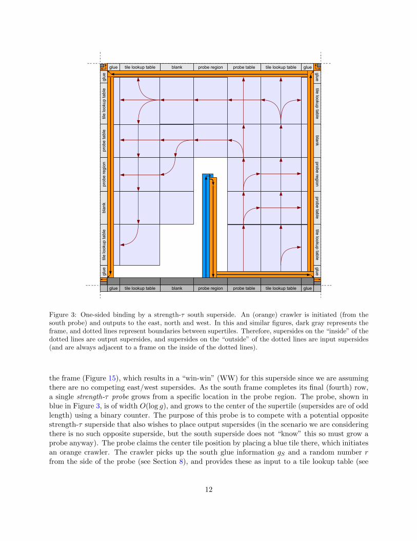
Figure 3: One-sided binding by a strength-τ south superside. An (orange) crawler is initiated (from thesouth probe) and outputs to the east, north and west. In this and similar figures, dark gray represents theframe, and dotted lines represent boundaries between supertiles. Therefore, supersides on the “inside” of thedotted lines are output supersides, and supersides on the “outside” of the dotted lines are input supersides(and are always adjacent to a frame on the inside of the dotted lines).
the frame (Figure 15), which results in a “win-win” (WW) for this superside since we are assumingthere are no competing east/west supersides. As the south frame completes its final (fourth) row,a single strength-τ probe grows from a specific location in the probe region. The probe, shown inblue in Figure 3, is of width O(log g), and grows to the center of the supertile (supersides are of oddlength) using a binary counter. The purpose of this probe is to compete with a potential oppositestrength-τ superside that also wishes to place output supersides (in the scenario we are consideringthere is no such opposite superside, but the south superside does not “know” this so must grow aprobe anyway). The probe claims the center tile position by placing a blue tile there, which initiatesan orange crawler. The crawler picks up the south glue information gS and a random number rfrom the side of the probe (see Section 8), and provides these as input to a tile lookup table (see
12

Section 10), which decides if the supertile should produce output sides. The random number r isused to simulate nondeterminism (i.e. if t is one of a set S of valid tiles that could be simulated).In the tile lookup table, the south glue gS is used to find the set of valid tiles S, and r is used tochoose t from S. Crawlers can be in one of 4 states unfilled, full, output, dead, described indetail in Section 9.3. All crawlers start in state unfilled.
After the tile-lookup the orange crawler changes to state full (since a single strength-τ glueis always sufficient to bind a tile), and its goal is to produce three output supersides. On the onehand, in the absence of other input supersides, the orange crawler succeeds at its goal and triggersthe growth pattern depicted in light blue in Figure 3. This growth pattern serves to output properlyencoded supersides to all other sides, and includes computing the correct output glues, strengthsand probe regions, as well as copying the remaining superside information. The computation ofcorrect output glues, strengths and probe regions is discussed in Sections 9 and 8. The crawlerchanges from full to output upon detecting that the east superside is empty (for details seeSection 9.4). On the other hand, if there are extra non-contributing input supersides (e.g. we aresimulating mismatches) the outputting crawler is designed to detect this and not output on thosesupersides. This behavior is described next.
5.2.1 One-sided binding with non-contributing input sides
We now deal with one-sided binding in the presence of non-contributing input supersides.5 Thefirst scenario we consider, shown in Figure 4, is one-sided binding where two opposite strength-τsupersides compete to see which should place output supersides. The two input supersides areopposite, and there are no adjacent supersides, therefore both supersides have win-win frames(Figure 14(2 .1)) and so they both grow probes. Within a supertile, probes meet (and block thepath of crawlers) only if we are simulating either (a) two-sided opposite binding for matchingopposite sides or (b) two opposite strength-τ sides. In all other cases probes do not meet andcrawlers can crawl over them (see Section 8). In Figure 4, the two strength-τ probes meet, andactually compete to see which will fill out the supertile: south wins this competition by being thefirst to claim the center tile position. When two strength-τ probes meet, they trigger the growth oftwo crawlers: one east crawler and one west crawler (both begin in state unfilled). Outputtingto the east side proceeds as before. Output to the north by the east-side crawler is prevented bythe east crawler carrying out a test in the north-east corner and detecting the presence of the northframe (see Figure 27(b) for details). This crawler also detects that the competing input superside tothe north is of strength τ (each frame tile encodes a single bit that flags whether or not a supersideis of strength τ). This information tells the east crawler to stop growing (it now knows that therewill be a north probe blocking the path to the west). Outputting to the west is handled by thewest crawler. As shown in Figure 4, the west crawler copies the south glue information gS and arandom number r from the south (blue) probe. The west crawler uses this information to do atile lookup along the north superside. Since both the east and west crawlers use the same inputs(gS , r), after the tile lookup they both encode the same output tile type t.
In one-sided binding (i.e. where a single input superside of strength-τ determines the encodedtile type), for all other scenarios of non-contributing input sides, opposite probes either do not growat all, or if they grow they to not meet. In this case a single outputting crawler moves counter-clockwise around the supertile. When the outputting crawler arrives at a corner it detects whether
5Non-contributing input supersides are input supersides that are not used to simulate tile binding. Mismatchingsupersides are one such an example.
13

glue tile lookup table blank probe region tile lookup tableprobe table glue
gluetile lookup tabl e
blankprobe region
tile lookup tabl eprobe table
glue
glue tile lookup table blankprobe region tile lookup tableprobe table glue
glue
tile
look
up ta
ble
blan
kpr
obe
regi
ontil
e lo
okup
tabl
epr
obe
tabl
egl
ue
collect south glue & random number
Figure 4: One-sided binding by a strength-τ south (S) superside, in the presence of a non-contributingstrength-τ north superside. The east (orange) crawler is initiated from the south probe and outputs to theeast. The west (also in orange) crawler is initiated from cooperation between the north (red) and south(blue) probes and outputs to the west.
or not there is a non-contributing input side, see Section 9.4 for details. If not, the outputtingcrawler produces an output side using the growth pattern shown in Figure 3. Otherwise, if thereis a non-contributing input side, the outputting crawler detects this and simply crawls across thenon-contributing input side.
5.3 Two-sided binding
We now describe the simulation of two-sided binding between adjacent supersides. Figure 5 illus-trates this for south and west cooperating adjacent supersides (the south is win-win, correspondingto Figure 14(2.3)). The orange crawler is initiated by cooperation between the south and westframes, in the south-west corner. This crawler picks up the west and south glue information(gW , gS) while in state unfilled, and grows towards the first (leftmost) tile lookup table on the
14

glue glue
glueglue
glue glue
probe region
probe region
blank
blanktile lookuptable
tile lookuptable
tile lookuptable
tile lookup table
probetable
probetable
blan
ktil
e lo
okup
tabl
etil
e lo
okup
tabl
epr
obe
tabl
egl
uegl
uepr
obe
regi
onblank
tile lookuptable
tile lookuptable
probetable
probe region
Figure 5: Two-sided binding for two adjacent sides on west and south. An (orange) crawler is initiated fromthe south-west corner and outputs to the east and north.
south superside. Upon entering the tile lookup table a random number r is generated, then thetile lookup is performed using (gW , gS , r) as input. The crawler transitions to state full uponcompleting the tile lookup. In the south-east corner, the full crawler detects the absence of aneast superside, transitions to state output, and produces the east and north output supersidesusing the growth pattern shown in Figure 5.
In Figure 5, as in many others, we show that there are probes that do not meet their com-plementary probes, to illustrate that the probes grow because the south superside, being win-win,does not “know” that eventually the west superside will arrive to initiate a crawler. However, sincethe north superside does not arrive, the west superside must be win on its left (north) end (i.e., theframe configuration matches in Figure 14(2.3)), so any north side cannot be win-win and thereforecannot grow any probes. Therefore the crawler (having knowledge of the frame configuration onthe west superside) safely proceeds across the probe region since it knows that no north probes willbe present.
15
blank
probetable
tile lookuptable
tile lookuptable
tile lookuptable
tile lookup table
probetable
blank
glue glue
glueglue
glue glue
glue
glue
probe region
probe region
collect north & south glues, & random number
blan
ktil
e lo
okup
tabl
etil
e lo
okup
tabl
epr
obe
tabl
epr
obe
regi
onblank
tile lookuptable
tile lookuptable
probetable
probe region
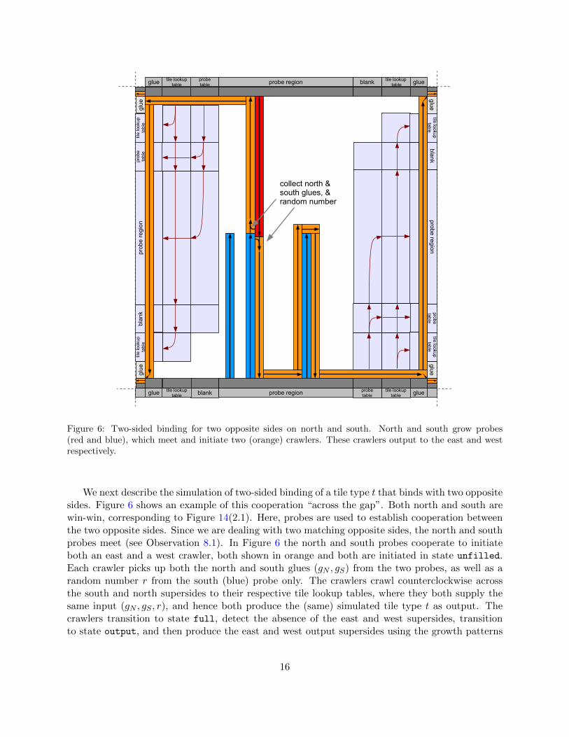
Figure 6: Two-sided binding for two opposite sides on north and south. North and south grow probes(red and blue), which meet and initiate two (orange) crawlers. These crawlers output to the east and westrespectively.
We next describe the simulation of two-sided binding of a tile type t that binds with two oppositesides. Figure 6 shows an example of this cooperation “across the gap”. Both north and south arewin-win, corresponding to Figure 14(2.1). Here, probes are used to establish cooperation betweenthe two opposite sides. Since we are dealing with two matching opposite sides, the north and southprobes meet (see Observation 8.1). In Figure 6 the north and south probes cooperate to initiateboth an east and a west crawler, both shown in orange and both are initiated in state unfilled.Each crawler picks up both the north and south glues (gN , gS) from the two probes, as well as arandom number r from the south (blue) probe only. The crawlers crawl counterclockwise acrossthe south and north supersides to their respective tile lookup tables, where they both supply thesame input (gN , gS , r), and hence both produce the (same) simulated tile type t as output. Thecrawlers transition to state full, detect the absence of the east and west supersides, transitionto state output, and then produce the east and west output supersides using the growth patterns
16
shown in Figure 6. So although the probe blocked the path across the center of the supertile, westill managed to share all the information required for the simulation of consistent binding of asingle tile type.
Note that this situation of across the gap cooperative binding and the previously describedsituations of one-sided binding in which the strength-τ probes meet are the only two situationsin which two physically separate crawlers are both in state output. This is safe to do since eachcrawler is initiated from the same probe and uses the same information to determine an outputtile type (hence make the same decision). In all other situations described subsequently, at mosta single crawler is ever in state output, to ensure that a consistent decision is made regarding theoutput tile type (if one exists).
In the absence of extra non-contributing input sides, all forms of two-sided binding are simulatedusing the above two techniques, or their rotations.
5.3.1 Two-sided binding with non-contributing input sides
Up to rotation, there are four cases for two-sided binding in the presence of additional non-contributing input sides.
Case (i): Two-sided adjacent binding with one adjacent non-contributing input superside (threesupersides total). Figure 7 gives an example where two adjacent sides (west and south) cooperateto simulate a tile binding, in the presence of a north non-contributing input side. The win-loseconfiguration is given in Figure 14(3.2). As per Figure 14(3.2), the orange crawler in Figure 7 isinitiated in the south-west corner in state unfilled, transitions to state full (encodes a simulatedtile type t ∈ T ) after the first tile lookup, and proceeds to output on the east (as happened inFigure 5). In the meantime a north superside arrives. The outputting orange crawler detects thepresence of the north superside at the north-east corner, and then stops growth as it knows thereare no further supersides to be output. Although the simulation of the binding of tile type t isessentially complete, at the north-west corner there is insufficient information to know this fact. Soa green crawler gets initiated at the north-east corner by cooperation between north and west. Thegreen crawler does its first tile lookup table on the west, and in the absence of knowledge aboutthe orange crawler, green makes a decision about whether it should remain in state unfilled ortransition to full. However, after green goes through its first tile lookup table on the south itdetects the state (full) of the orange crawler directly to its south. Green now knows that orangehas already claimed responsibility for encoding the simulated tile type t, therefore green entersstate dead and stops growth.
For the same win/lose scenario for these three frames (north, south, west), another possible orderof growth is where the green crawler arrives at the south-west corner before the orange crawler isinitiated. In this case there is no orange crawler, the green crawler transitions to state full uponcollecting the glue from the south superside, then state output upon successfully reaching the eastsuperside and proceeds to output the east superside.
For the win/lose configuration in Figure 14(3.1) (where one of the sides is a non-contributinginput side) the orange and green crawlers act similarly as in Figure 14(3.2) just described, the onlydifference being the presence/absence of non-blocking probes on the various sides. For the win/loseconfigurations in Figures 14(3.3) and 14(3.4), the situation is somewhat simpler to describe as onlyone crawler is created; we omit the details.
Case (ii): Two-sided adjacent binding with two adjacent non-contributing input sides (foursupersides total). This is similar to Case (i), the only difference being that the full crawler detects
17

probetable
tile lookuptable
tile lookup tableblank
glueglue
glue glue
blanktile lookuptable
tile lookuptable
probetableglue glueprobe region
probe region
blan
ktil
e lo
okup
tabl
etil
e lo
okup
tabl
epr
obe
tabl
egl
uegl
uepr
obe
regi
onblank
tile lookuptable
tile lookuptable
probetable
probe region
stops here because other crawler has sufficient strength
Figure 7: Two-sided binding for two adjacent sides on west and south, with an additional non-contributinginput side to the north. An (orange) crawler is initiated from the south-west corner and outputs to the east.West and north also initiate cooperation by producing a (green) crawler, which halts when it detects thatorange is already outputting.
the presence of both non-contributing input sides and stops growing, and thus does not outputany supersides. However, immediately before stopping growth the full crawler transitions to stateoutput and grows a single column of O(log g) tiles that encode the simulated tile type t ∈ T (fordetails, see Figure 27(c)). In order to determine the encoded tile type from T , the representationfunction R checks these O(log g) tiles.
Case (iii): Two sided opposite binding, with one adjacent non-contributing input side (three su-persides total). Figure 8 shows a simulation of Figure 14(3.4), where the west is a non-contributinginput side. Probe locations within the probe region are such that probes meet if we are simulatingtwo matching opposite sides (Observation 8.1), as is the case here. In Figure 8 the probes meetand cooperate (as was described above for Figure 6). In the meantime a green crawler is initiatedfrom the north-west corner. After green does its second tile lookup on the south side it halts as by
18

blank
probetable
tile lookuptable
tile lookuptable
tile lookuptable
tile lookup table
probetable
blank
glue glue
glueglue
glue glue
probe region
probe region
collect N/S glues and random number
collect N/S glues
blan
ktil
e lo
okup
tabl
etil
e lo
okup
tabl
epr
obe
tabl
egl
uegl
uepr
obe
regi
on
stops here because probes will meet
blanktile lookup
tabletile lookup
tableprobetable
probe region
Figure 8: Two-sided binding for two opposite win-win sides on north and south, with an additional non-contributing input side to the west. North and south grow probes (red and blue), which meet and initiate(orange) crawlers. The east crawler outputs a superside to the east, while the west crawler is preventedfrom outputting by the presence of a non-contributing input superside to the west. West and north initiatecooperation by producing the green crawler, which halts after it knows that the center of the supertile isblocked by probes.
this time it has sufficient information (i.e. north glue, south glue, and the win/lose configuration ofthe three frames) to know that north and south match, and will grow probes that meet and blockthe path to the east. The orange crawler outputs to the west.
For the same win/lose scenario for these three frames (north, south, west), another possibleorder of growth is where the west orange crawler arrives at the north-west corner before the greencrawler is initiated. In this case there is no green crawler. The west orange crawler detects thepresence of the frame of the west superside, transitions to state output, and stops growth.
If the non-contributing input side is instead on the west, a rotated version of the previoussimulation is used.
19

Case (iv): Two sided opposite binding, with two adjacent non-contributing input sides (foursupersides total). This win/lose scenario is shown in Figure 14(4.1). This is similar to Case (iii),the only differences being (a) that up to four crawlers are created (two corresponding to the greenarrows in Figure 14(4.1) and two originating from the meeting probes) and (b) the two outputtingcrawlers (those coming from the probes) detect the presence of both non-contributing (lose-lose)input sides, transition to state output, and stop growth.
For cases (i)-(iv) above we have omitted description of their rotations, and we did not explicitlylist all win/lose frame configurations. However, the same style of argument applies for all thesescenarios.
probe region
probetable
tile lookuptable
tile lookup tableblankglue glueprobe region
blan
ktil
e lo
okup
tabl
etil
e lo
okup
tabl
epr
obe
tabl
egl
uegl
uepr
obe
regi
on
probetable
tile lookuptable
tile lookup tableblank
glueglue
glue glue
blanktile lookuptable
tile lookuptable
probetableglue glueprobe region
probe region
blan
ktil
e lo
okup
tabl
etil
e lo
okup
tabl
epr
obe
tabl
egl
uegl
uepr
obe
regi
on
blanktile lookup
tabletile lookup
tableprobetableunfilled crawler waits for
south input superside
south superside arrives, continues crawler, which becomes full with addition of south glue
Figure 9: Three-sided binding with input supersides on the north, west and south. An (orange) crawler isinitiated from the north-west corner but has insufficient glue information to output so waits at the south-westcorner. When the south superside arrives, the crawler continues, which after a table lookup becomes full, soit has sufficient glue information to simulate the placement of a tile type and thus outputs on the east.
5.4 Three-sided binding
Figure 9 shows a three-sided binding scenario with win/lose configuration given in Figure 14(3.1).An (orange) crawler is initiated from the north-west corner but has insufficient glue informationto output, so it waits at the south-west corner in state unfilled. Eventually the south supersideappears. The orange crawler cooperates with the south, gathers the south glue, does a tile lookupand transitions to state full. The crawler outputs to the east. The purpose of this example isto illustrate the asynchronous nature of superside cooperation: where appropriate, crawlers mustwait for potential input supersides.
Figure 10 illustrates north, west and south cooperating supersides (north and south are bothwin-win, corresponding to Figure 14(3.4). The south-west corner does not initiate a crawler: ascan be seen in Figure 14(3.4) the frames at this corner know that there will be a crawler coming
20

probetable
tile lookuptable
tile lookup tableblank
glueglue
glue glue
blanktile lookuptable
tile lookuptable
probetableglue glueprobe region
probe region
blan
ktil
e lo
okup
tabl
etil
e lo
okup
tabl
epr
obe
tabl
egl
uegl
uepr
obe
regi
on
continues here because probes will not meet
blanktile lookup
tabletile lookup
tableprobetable
probe region
Figure 10: Three-sided binding with input supersides on the north, west and south. A single (orange) crawleris initiated from the north-west corner and outputs to the east. North and south grow probes, that do notmeet.
from north-west corner. The north-west corner initiates an (orange) crawler that travels counter-clockwise gathering glues from the three input supersides. After completing its second tile lookup(on the left of the south superside) the orange crawler transitions to state full. Since north andsouth are win-win they both grow probes. However in this case the north and south supersideshave insufficient strength to match, so, by Observation 8.1, their probes do not meet. The orangecrawler crawls along the south superside, outputs on the east, and then halts.
Another very similar case, shown in Figure 14(3.3) is where north is win-win and west andsouth are both lose-win. This case is handled exactly as in the previous one, the only differencebeing that there is no south probe present.
Another class of cases is where we have three-sided binding, with up to two crawlers. Thisoccurs with frame configurations given by Figures 14(3.1) and 14(3.2) and an example is illustratedin Figure 11. In Figure 11 the south frame is win-win and grows probes (i.e. Figure 14(3.2)). An
21

probetable
tile lookuptable
tile lookup tableblank
glueglue
glue glue
blanktile lookuptable
tile lookuptable
probetableglue glueprobe region
probe region
blan
ktil
e lo
okup
tabl
etil
e lo
okup
tabl
epr
obe
tabl
egl
uegl
uepr
obe
regi
onblank
tile lookuptable
tile lookuptable
probetable
probe region
Figure 11: Three-sided binding with input supersides on the north, west and south. An (orange) crawler isinitiated from the south-west corner but has insufficient glue information to output so waits at the south-east corner. A (green) crawler is initiated from the north-west corner, and has sufficient glue information tosimulate the placement of a tile type and thus outputs on the east.
(orange) crawler is initiated in the south-west corner, however after going through the first tilelookup (on the left side of the south superside) it has insufficient strength from the south andwest glues to simulate binding of a tile type. The orange crawler (in state unfilled) waits at thesouth-east corner (waiting to cooperate with a possible east superside). In the meantime a (green)crawler is initiated in the north-west corner, by the time it does a tile lookup on the south (usingglue information from north, west and south) it transitions to state full as it has sufficient gluesand strength to simulate binding of a tile type. The green crawler crawls over the orange crawlerand outputs on the east side (see Figure 29(b) for details).
For the same win/lose scenario for these three input sides, another possible order of growth iswhere the green crawler arrives to the south-west corner before the orange crawler is initiated. Inthis case the green crawler simply transitions to full, after doing a tile lookup on the south, and
22

proceeds to output on the east.The same arguments work for all rotations of these 3-sided binding cases.
5.4.1 Three-sided binding with a non-contributing input side
Three-sided binding in the presence of an additional non-contributing input side is conceptuallyidentical to the case of four-sided binding, the only difference being the number of glues thatcontribute in a table lookup, and the fact that one crawler will try to output a superside (andfail). Therefore we omit explicit discussion of these cases, since four-sided binding is discussed inSection 5.5.
5.5 Four-sided binding
In terms of win/lose configurations, there are six 4-sided cases given in Figure 14(4.1)–(4.6). Whensimulating four-sided binding, it is not necessary to produce output supersides, so crawlers use thestate output solely to define the simulated tile type (i.e. to communicate to the representationfunction R).
One of the simplest cases to consider is shown in Figure 12. Here the win/lose configuration iseither of Figures 14(4.5) or 14(4.6). No probes are created, and a single crawler gathers all fourglues, at which point it transitions to state output, and lays down a row of O(log g) tiles thatdescribe the simulated tile type t. If there is no matching tile type, it transitions to state dead.The win/lose configuration of Figure 14(4.3) is handled in a very similar way, there is a (useless)probe and a single crawler that actually does the work.
The remaining three win/lose configurations are given in Figure 14(4.1), (4.2) and (4.4). Up totwo crawlers are created. For four-sided binding, our construction is designed so that (a) if there isexactly one crawler, it simulates binding as required, and (b) if there are two crawlers then at somepoint both crawlers become aware of each others’ presence, and one transitions to state dead whilethe other transitions to state output. The latter crawler encodes the output tile type. Rather thangiving an exhaustive analysis at this point, we describe an example in Figure 13, which has win/loseconfiguration shown in Figure 14(4.1). Since this is four-sided binding, the opposite probes do notmeet (Observation 8.1) in Figure 13. Two crawlers are initiated, as shown in Figure 14(4.1). Theorange crawler is unfilled by the time it has gathered 3 glues, when it reaches the south-east cornerit detects the green crawler (i.e. orange fails to claim point of competition POC1), reads the eastglue, and does a tile lookup. There is a crawler precedence (based on the initiation corner: NW> SW > SE > NE, see Section 9.3), so since orange has highest precedence it transitions to statefull, then immediately transitions to state output. When the other (green) crawler detects thepresence of the orange crawler (in the north-west corner) it stops growth as it has lower precedence.
The general rule here is that if a crawler learns the win/lose configuration of all 4 supersides(including the fact that there are four input supersides), and from that learns that there is/will bea second crawler with higher precedence, then it stops growth. If it learns that it is the crawlerwith highest precedence, then it outputs a tile type from T .
6 Correctness of construction
As a reminder of notation, let g be the number of glues in the tile set T of the simulated tileassembly system T .
23
probetable
tile lookuptable
tile lookup tableblankglue glue
blanktile lookuptable
tile lookuptable
probetableglue glueprobe region
probe region
blan
ktil
e lo
okup
tabl
etil
e lo
okup
tabl
epr
obe
tabl
egl
uegl
uepr
obe
regi
on
encodes tile here because it now has all four glues to make decision
blanktile lookup
tabletile lookup
tableprobetable
glueglue
probe region
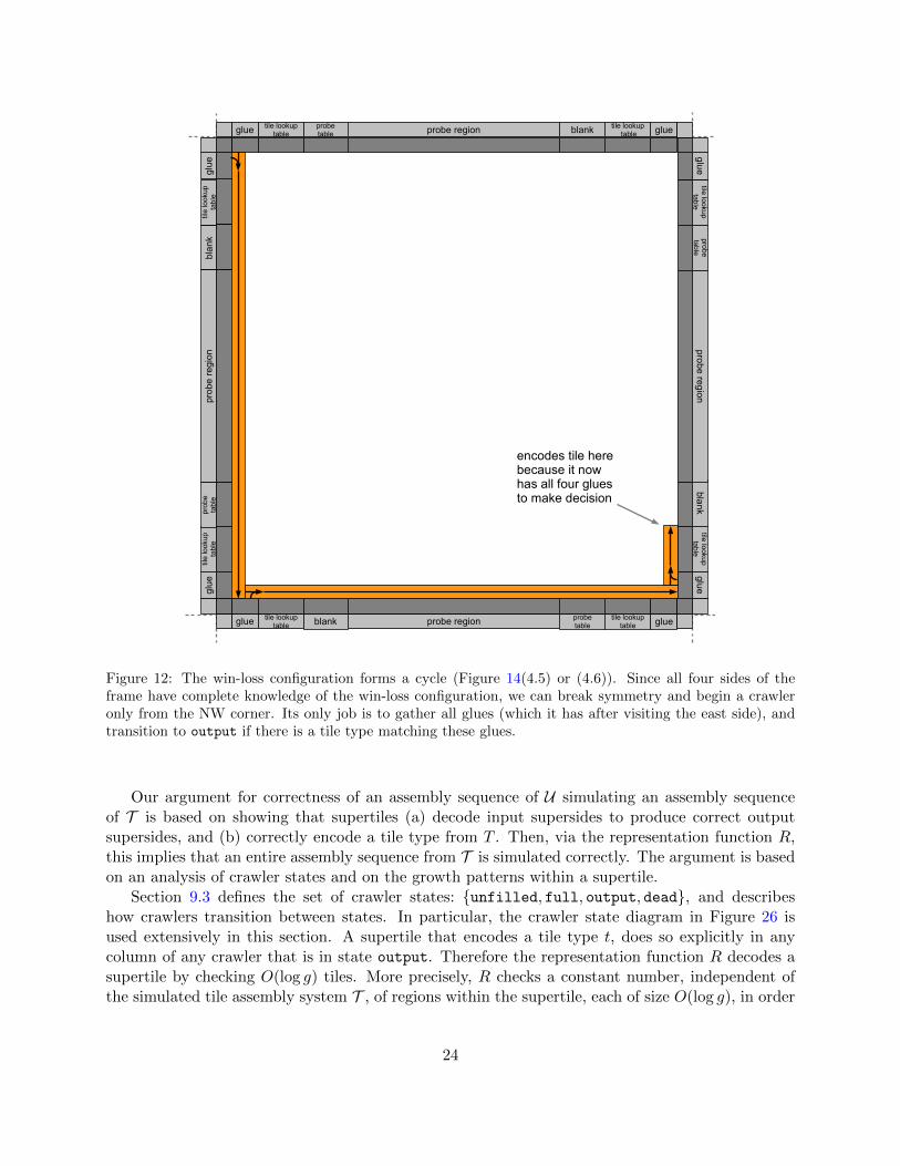
Figure 12: The win-loss configuration forms a cycle (Figure 14(4.5) or (4.6)). Since all four sides of theframe have complete knowledge of the win-loss configuration, we can break symmetry and begin a crawleronly from the NW corner. Its only job is to gather all glues (which it has after visiting the east side), andtransition to output if there is a tile type matching these glues.
Our argument for correctness of an assembly sequence of U simulating an assembly sequenceof T is based on showing that supertiles (a) decode input supersides to produce correct outputsupersides, and (b) correctly encode a tile type from T . Then, via the representation function R,this implies that an entire assembly sequence from T is simulated correctly. The argument is basedon an analysis of crawler states and on the growth patterns within a supertile.
Section 9.3 defines the set of crawler states: unfilled, full, output, dead, and describeshow crawlers transition between states. In particular, the crawler state diagram in Figure 26 isused extensively in this section. A supertile that encodes a tile type t, does so explicitly in anycolumn of any crawler that is in state output. Therefore the representation function R decodes asupertile by checking O(log g) tiles. More precisely, R checks a constant number, independent ofthe simulated tile assembly system T , of regions within the supertile, each of size O(log g), in order
24

probetable
tile lookuptable
tile lookup tableblankglue glue
blanktile lookuptable
tile lookuptable
probetableglue glueprobe region
probe region
blan
ktil
e lo
okup
tabl
etil
e lo
okup
tabl
epr
obe
tabl
egl
uegl
uepr
obe
regi
on
encodes tile here because it now has all four glues to make decision
blanktile lookup
tabletile lookup
tableprobetable
glueglue
probe region
to break symmetry, NW crawler decides output tile type, knowing SE crawler will stop
to break symmetry, SE crawler stops, knowing NW crawler will decide output tile type
Figure 13: Two crawlers are initiated when four sides are present. After crawling for two sides, each learnsthat there are four sides, as well as the entire supertile’s win-loss configuration. At this point, the crawlerwith higher precedence (orange) continues, while the lower-precedence crawler (green) halts. This is becauseif the four sides have sufficient strength to bind, only one crawler should transition to output; the orangecrawler does this after reading the lookup table on the east side, transitioning to full and then immediatelyto output (since it knows there are no empty sides necessary to output to).
to determine t.6
We consider three cases that represent three different types of supertile formation, and arguethat in each case the correct tile type t is simulated, otherwise no tile type is simulated.Case 1. Claim: If a supertile simulates binding across the gap7, there are exactly two crawlers inthe supertile that transition to the state output and both encode the same tile type t ∈ T .
Proof sketch: By Observation 8.1, simulating binding “across the gap” involves either (1a) two
6Thus R is a very simple representation function in the sense that it has very low computational complexity: usingreasonable (standard) encodings of tiles as bit strings, it is contained in FAC0 (the function analog of the constantdepth unbounded-fanin Boolean circuit compleity class AC0).
7The term binding across the gap refers to binding that is initiated by two probes that meet, see Observation 8.1.
25

probes, each representing strength < τ glues, meeting to cooperate, or (1b) two strength-τ probesthat meet (one of which wins the competition between them). In the case of (1a), immediatelyafter the probes meet, two crawlers in state unfilled are initiated that both go on to transitionto state full after their first tile table lookup (see Figures 6 and 8). Since both crawlers usedthe same input glues and random number (gathered from the south or west probe) in their tilelookup, when they enter the state full both encode the same tile type t. If there are no other (i.e.non-contributing) input supersides, these crawlers transition to state output and output the tworelevant encoded output sides of tile t (e.g. Figure 6). If there is one or two non-contributing inputsides, then when a full crawler detects this (by failing to claim a specific “point of competition”,called POC2, because of the presence of a frame, as shown in Figure 27(c)) it transitions to stateoutput, produces a single column of O(log g) tiles that encode t ∈ T and immediately stops growing(see Figures 8 and 27(c) for details).
The case of (1b) is analogous: the two strength-τ probes connect in the middle. The one thatwins the competition initiates a crawler independently of whether the losing probe is present. Thearrival of the second probe initiates a second crawler, which in analogy to case (1a) uses the sameglue information and random number as the first crawler, guaranteeing that it enters state full,and then output encoding the same output tile type as the first crawler.
For both (1a) and (1b), besides probe-initiated crawlers, the only other crawlers that get ini-tiated are due to the arrival of third or fourth input supersides (whose frames are necessarilylose-lose). Each such superside initiates at most one such new crawler. As usual, the crawler crawlsfrom the left end to the right end of the lose-lose superside. It meets the win-win superside, thendoes a tile lookup on the win-win superside (the green crawler in Figure 8 is an example). Immedi-ately after the tile lookup the crawler enters state dead, as it has enough glue information to decidethat both probes meet up ahead (and that there are other crawlers whose job it is to encode thetile type). This state change is defined in Figure 26, and illustrated in Figure 8.Case 2. Claim: If the supertile simulates binding that is not “across the gap”, there is exactly onecrawler in the supertile that transitions to state output (and thus the supertile uniquely encodessome tile type t ∈ T ).
Proof sketch: As defined in Figure 26, transitioning to the state output can happen in one oftwo ways (2a) or (2b), both from state full:(2a) A crawler cfull1 in state full claims POC2, i.e., it succeeds in constructing an output superside.Figure 27(a) shows a full crawler claiming POC2. There are three subcases to consider, (2a.1),(2a.2) and (2a.3):
(2a.1) The crawler cfull1 came from the previous corner in the clockwise direction. From Fig-ure 14, at most one other crawler c2 can be initiated. If c2 exists, it came from the corner previousto the corner that initiated cfull1 (because one superside is empty). If c2 is initiated it will eventuallypiggyback on the full crawler cfull1 and then stop growth in state dead and so c2 never gets tostate output (Figure 26 defines this behavior of c2, and an example is shown in Figure 7).
(2a.2) The crawler cfull1 came from two corners previous: again there will be no other crawlersthat enter state full, because either cfull1 piggybacks on an unfilled crawler c2 and thus cfull1
completely covers c2 (since cfull1 claims POC2, see Figures 29(b) and 11), or else there are no othercrawlers at all. (If cfull1 piggybacks on a full crawler then it will enter state dead before reachingthe empty superside, so it could not have claimed POC2.)
(2a.3) The crawler came from a strength-τ probe. The crawler enters state output upon claimingPOC2, and proceeds to output. It also outputs supersides for any other supersides where it can
26

claim POC2. Any other crawler that is initiated comes from a previous corner and stops growthwhen it meets the strength-τ superside (Figure 26).(2b) There are four supersides, and there is no other crawler with higher precedence that willeventually transition to output:
As Figure 14 shows, the frame initiates at most two crawlers. One crawler: If a crawler gathersfour glues directly from four frames (claiming POC1 at each frame), then it knows that there are,and will be, no other crawlers. If it is full at this point it immediately transitions to state output,grows a single column of O(log g) tiles encoding the tile type t, and then stops growth. An exampleis shown in Figure 12. If it is not full at this point, it simply enters state dead and stops growth(i.e. the supertile encodes no tile from T ).
Two Crawlers: If there are four input sides and two crawlers (see Figure 14), there is a simplealgorithm that causes one crawler to enter the dead state, and the other crawler (after collectingall 4 glues) to enter the output state. The basic rule is: if a crawler c1 is in state full and learns(from reading win/lose frame information) that it is the highest precedence crawler, or that a higherprecedence crawler would have piggybacked on c1 when c1 was full, then it immediately transitionsto output. Note, that the necessary information not contained in the frame (location of the lookuptable where c1 transitioned to full) can be stored in a constant number of bits by c1. This rule isdefined in Figure 26.Case 3. Claim: If the supertile should not simulate any tile type, then there are no crawlers instate output within that supertile location in a producible terminal assembly.
Proof sketch: We argue that no crawler transitions to state full, which implies that no crawlertransitions to state output, for all cases where we should not simulate placement of a tile typefrom T . If there are no input supersides, then no growth occurs within the supertile. If there isone input superside that has strength < τ , no crawlers are initiated (Section 9.1). If there areexactly 2 opposite supersides that do not represent glues (of sufficient strength) on any tile typet ∈ T , then their probes do not meet (see Observation 8.1), and thus no crawlers are initiated. Ifthere are exactly 2 adjacent input supersides, that do not represent any tile type t ∈ T , or haveinsufficient strength for binding, then an unfilled crawler c is initiated at their corner. Crawler cgoes through a tile lookup, remains in state unfilled, crawls to the right end of a superside, andwaits (forever) in state unfilled, for a third input superside that never arrives (an example of anunfilled waiting crawler is shown on the left side of Figure 9). If there are exactly 3 adjacentinput supersides that do not represent glues (of sufficient strength) on any tile type t ∈ T , thenfirst, we know that no probes meet (and so no crawlers are generated from probes). We also knowthat either one or two crawlers are initiated from the two corners, which remain in state unfilled,forever waiting for an input superside that never arrives (Figure 28(b)). If there are exactly 4 inputsupersides that do not represent glues (of sufficient strength) on any tile type t ∈ T , then eitherone or two crawlers are created and that will transition to state dead after gathering 4 glues anddoing a tile lookup.
7 The Frame
The frame is the portion of a supertile consisting of the outermost 4 rows on supersides that serve aspotential input supersides for the creation of that supertile. The growth of any particular supersideof a frame is dependent upon there being an adjacent supertile that has placed an “output” supersideadjacent to this newly forming supertile (which uses it as an “input” superside), and therefore the
27

1 Side
W W
2 Sides (opp)
W W
2.1
2 Sides (adj)
2.2
L W
3 Sides
W
W
3.1
L W
L W
L
W
3.2
W W
W W
W
L
3.3
L W
W W
L
L
3.4
W W
W W
4 Sides
L
L
4.1
W W
W W
L
L
4.2
W L
W W
W
L
4.3
L W
W W
W
L
4.4
L LL
L
W
L
L
L
W
L
L W
L
W
4.5
W L
W L
W
L
4.6
L WW
L
L
W
W
W
WL
2 Sides (adj)
2.3
L
W
WW
1.1
W W
Figure 14: Win-Lose scenarios for all possible combinations of input supersides (with rotationally equivalentscenarios omitted). Green arrows show corners from which crawlers will begin and the directions in whichthey will grow.
28

frame for a particular supertile may consist of any non-empty subset of such input supersides.The growth of the frame executes a sort of distributed algorithm in which supersides either
grow or wait for adjacent supersides to grow before growing, so as to incorporate that superside’sinformation into their own. The basic frame formation algorithm is this: if “I” (a superside) win onboth ends, then I fill in four layers that encode this information (see Figure 15). If I lose on eitherend, then this means there is a superside there that won, so I wait for it to fill in its four layersbefore forming my own four layers. This is because I want to incorporate all the information thatthe adjacent winning superside is able to gather into my own frame layer. This idea almost works,except that two cases (4.5 and 4.6) in Figure 14 have a Dining Philosopher’s deadlock problem: allsupersides lost exactly one end, so all of them wait forever. Most of the complexity of the framealgorithm (and the need for four layers rather than just two) stem from the need to handle thesecases.
The fix for these cases, at an intuitive level, works roughly as follows. The south, north, andeast supersides work as described. The west superside is special. If west loses on both ends, thenthe configuration cannot be 4.5 or 4.6 in Figure 14, so it is safe for both ends to wait since framesof adjacent supersides will eventually arrive. Otherwise, if the west superside loses on exactlyone end, then it sends a row of tiles (designated the “WAI signal”, standing for “Waiting onAdditional Information”) towards the winning end. The WAI signal propagates around the edgeof the supertile within the frame. For concreteness assume the losing end of the west superside isright (south) and the winning end is left (north).
Two scenarios are possible: either the win-loss configuration is 4.5 (in our concrete example) inFigure 14, or not. If so, then the WAI signal eventually traverses the entire supertile and reachesback to the west superside (on its losing end) to serve as the signal that the west superside’s losingend was waiting for. At this point, the entire frame can fill in with the complete informationdescribing the win-loss configuration (hence each superside’s frame will have complete commonknowledge of all supersides).
If the win-loss configuration is not 4.5 in Figure 14, then at least one superside to the right ofwest’s losing end must win on its right end. Therefore this superside is guaranteed to completeits frame, and all supersides between west and this superside (which all lost on their right end,including west) will receive the signal they are waiting for. In this scenario, the WAI signal is notneeded, and it will “bounce” off of the first superside it encounters that wins on its right (guaranteedto exist as we just observed), without getting all the way around the supertile (which may not evenbe possible if there is a missing superside). But it is acceptable for the WAI signal not to makeit all the way around, since in this scenario a different signal (that of the superside that won onits right end) will reach the losing end of the west superside. Therefore in either scenario, west’slosing end is guaranteed to receive the signal it is waiting for, preventing deadlock.
We now formally describe the frame construction algorithm. The first (outermost) layer of theframe serves merely as a “spacer” row and grows each superside (N, E, S, and W) as 2 independentpieces, with each beginning assembly from a position immediately adjacent to a corner of thesquare space to be occupied by the supertile forming. Each such half-row grows from its startinglocation (which is initiated by a strength 2 bond from the output superside of the input supertile)toward the center of its superside, stopping one location short of the center. This growth utilizescooperation with the input supertile, thus transferring information about that input glue, etc.,into the frame, and also prevents any frame growth along supersides that don’t have inputs. Thistransfer of information from the input sides is continued through all levels of the frame, resulting
29

DD
a
b
c
d
e
Figure 15: The growth sequence of a WW superside of a frame for arbitrary direction D. Layers cooperatevia strength 1 glues on North and South supersides except where bonds are explicitly shown with black tabs.(a) Layer 1 grows from each end towards the center, stopping with a one-tile gap. (b) The superside winsboth competition corners, then grows toward the center. (c) Layer 2 completes via a single tile that bindsvia cooperation between the two halves, and exposes a double strength bond upward. Note that this tilecontains the information that this superside was WW and passes that along. (d) Layer 3 grows by firstattaching a tile to the double strength bond in the center of Layer 2, then grows outward to both supersides.(e) Layer 4 grows in the same way as Layer 3. The leftmost and rightmost tiles of Layer 4 expose singlestrength glues on their tops that can initiate frame growth for the losing supersides to the left and right (ifthey exist) and also pass along information that superside D is WW . Furthermore, only if D is South (orNorth), then the second leftmost (rightmost) tile also exposes such a glue.
in the interior of the frame having all of the necessary information in its exposed glues so thatthe next modules of the construction can form. In the few cases where frame tiles don’t requirecooperation on their outer edges for assembly, those positions are intentionally left empty by theinput supertile in terms of output information. See Figure 20-1 for an example of the formation ofthe first layer of a frame for a supertile with 4 input supertiles.
The first tiles that must be placed for any superside of Layer 2 of a frame are competition tiles(pictured as the dark grey tiles in Figure 20. Competition tiles bind with strength 2 bonds to theirinput tiles from Layer 1, which are in turn similarly bound to their input supertiles. Thus, clearlyfor each competition tile position only one adjacent supertile can serve as the input that initiatesits assembly. In the case where there are two previously assembled supertiles at positions necessaryto initiate the placement of a particular competition tile, the actual competition tile that is placedrepresents a nondeterministic “competition” determining which one of those supertiles is actuallybound to (with the other having a glue mismatch). We say that the supertile that is bound to winsthe competition (often denoted simply by a W ), and the other loses (L). When talking about theW/L pair for a particular superside, we denote it as WW , WL, LW , or LL with the first of thepair referring to the LEFT end and the second to the RIGHT end.
30

L R
L R
L R
D,L,RD,L,R
a
b
c
(a) The growth sequence of a LL superside of a framefor direction D ∈ N,E, S. (a) This superside losesboth competitions, and since it is not the West super-side must wait for adjacent supersides to initiate growthof the second layer. (b) Both adjacent supersides, in di-rections represented by L and R, complete. (c) Layer 4of each adjacent superside initiates the growth of Layer2 of this superside, and the growth of the remaining lay-ers is similar to that shown for Layers 2 through 4 inFigure 15, with the addition that the configuration in-formation about supersides L and R is also combinedwith the information about this superside. Note thatthe additional case of a WAI signal being passed by anadjacent superside is shown in Figure 16b.
L
L
WAI
WAI
L
L
D,L,RWAI
WAI
R
RD,L,R
a
b
c
(b) The growth sequence of a LL superside of a framefor direction D ∈ N,E, S but with a WAI signalpassed in through an adjacent superside. (a) This su-perside loses both competitions, and since it is not theWest superside must wait for adjacent supersides toinitiate growth of the second layer. (b) The R end ini-tiates half of Layer 2 with a WAI signal and the Lend’s frame completes and initiates the other half ofLayer 2. Since this superside is LL, the middle ini-tiates Layer 3 that only grows one end and does notpropagate WAI. (c) The completion of R’s frame ini-tiates the completion of Layer 3 whose middle is ableto gather information about D, L, and R and initiateLayer 4.
Figure 16: Examples of LL superside frame growth for supersides other than the West and beginning afterthe formation of Layer 1 that is shown in Figure 15 and is the same for all configurations.
Along with the subset of neighboring supertiles present, the pattern of W and L positionsalong with some nondeterminism based on asynchronous timing determine how the rest of a frameassembles. The entire algorithm for the growth of all supersides follows. Also, Figure 20 showsone possible growth sequence of a frame for a supertile with 4 potential input supersides, whileFigures 21 and 22 show completed frames for supertiles with 4 potential input supersides thathave differing W/L patterns. The full set of potential combinations of input supersides and W/Lconfigurations (excluding rotational duplicates) can be seen in Figure 14.
Following is the frame formation algorithm, which specifies the growth of the 4 layers of theframe. Note that there are unique tile types for each superside and for each piece of informationbeing passed such as W/L pairs for (possibly multiple) sides. Throughout the following algorithm,let D ∈ N,S,E,W and S ∈ W,L. Each layer is broken into 3 components, the halves, whichare the portions including a corner and extending toward the center but stopping one tile short ofthe center position, and the middle, which is the single tile position between 2 halves. Note thatin some cases the middle may be one position away from the actual center of the row and thusone half is correspondingly one tile longer and the other is one shorter, and due to the fact thatL-halves begin growth from portions of adjacent frame sides that have completed, they are shorterthan W-halves. We say S-half to refer to a half that is on the S superside of a layer.
Note that scenarios 4.5 and 4.6 create conditions of potential deadlock in which all supersideshave the same W/L configuration. To “break symmetry” and avoid deadlock, we designate the
31
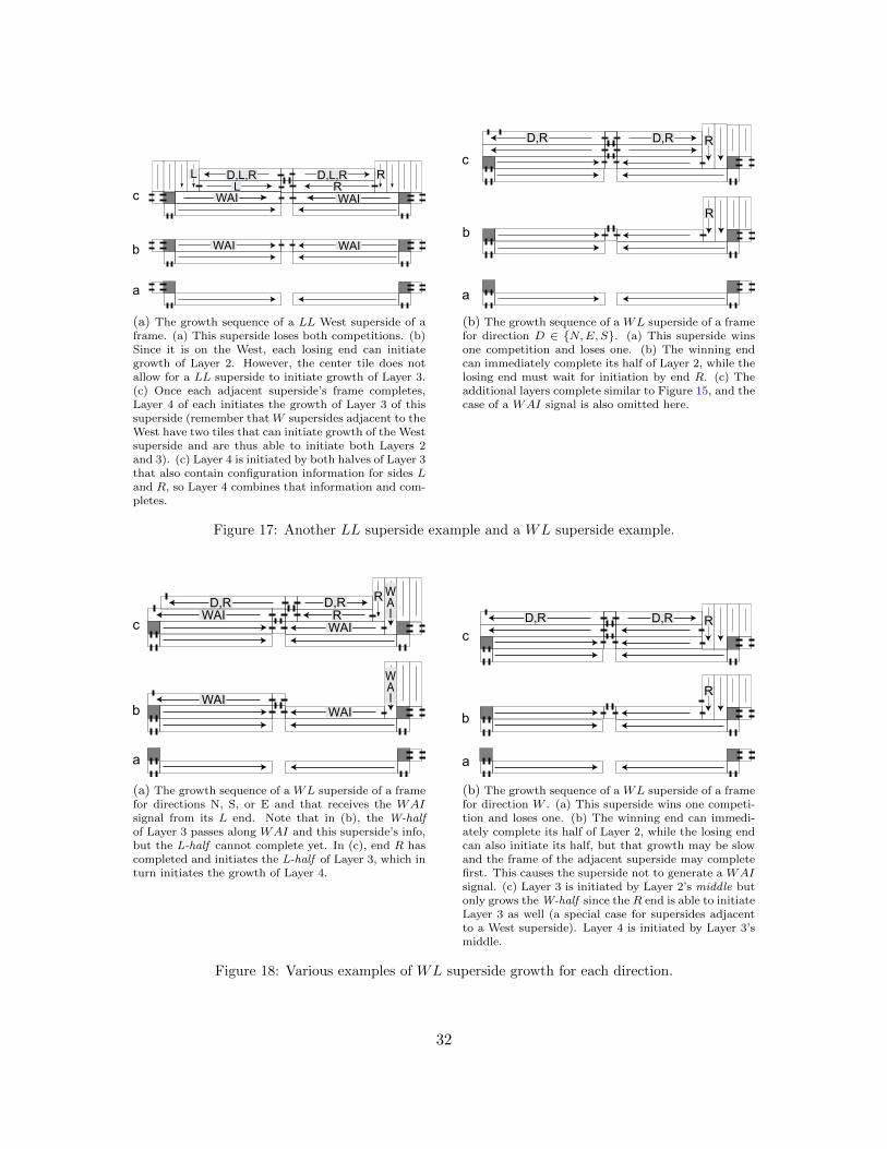
a
b WAIWAI
cL R
D,L,RD,L,RL R
WAIWAI
(a) The growth sequence of a LL West superside of aframe. (a) This superside loses both competitions. (b)Since it is on the West, each losing end can initiategrowth of Layer 2. However, the center tile does notallow for a LL superside to initiate growth of Layer 3.(c) Once each adjacent superside’s frame completes,Layer 4 of each initiates the growth of Layer 3 of thissuperside (remember that W supersides adjacent to theWest have two tiles that can initiate growth of the Westsuperside and are thus able to initiate both Layers 2and 3). (c) Layer 4 is initiated by both halves of Layer 3that also contain configuration information for sides Land R, so Layer 4 combines that information and com-pletes.
R
a
b
R
c
D,RD,R
(b) The growth sequence of a WL superside of a framefor direction D ∈ N,E, S. (a) This superside winsone competition and loses one. (b) The winning endcan immediately complete its half of Layer 2, while thelosing end must wait for initiation by end R. (c) Theadditional layers complete similar to Figure 15, and thecase of a WAI signal is also omitted here.
Figure 17: Another LL superside example and a WL superside example.
a
b
c
WAI
WAIWAI
WAI
WAIWAI
R
RD,RD,R
(a) The growth sequence of a WL superside of a framefor directions N, S, or E and that receives the WAIsignal from its L end. Note that in (b), the W-halfof Layer 3 passes along WAI and this superside’s info,but the L-half cannot complete yet. In (c), end R hascompleted and initiates the L-half of Layer 3, which inturn initiates the growth of Layer 4.
a
b
c
R
RD,RD,R
(b) The growth sequence of a WL superside of a framefor direction W . (a) This superside wins one competi-tion and loses one. (b) The winning end can immedi-ately complete its half of Layer 2, while the losing endcan also initiate its half, but that growth may be slowand the frame of the adjacent superside may completefirst. This causes the superside not to generate a WAIsignal. (c) Layer 3 is initiated by Layer 2’s middle butonly grows the W-half since the R end is able to initiateLayer 3 as well (a special case for supersides adjacentto a West superside). Layer 4 is initiated by Layer 3’smiddle.
Figure 18: Various examples of WL superside growth for each direction.
32

a
bWAI
WAI
c WAIRD,R D,R
RWAI
(a) The growth sequence of a WL West superside of aframe when the WAI signal does not make it all theway around the frame (i.e. not scenarios 4.5 or 4.6).(a) This superside wins one competition and loses one.(b) The winning end can complete its half of Layer 2,and since this is the West superside, so can the losingend. However, when the meet in the center the halvesof Layer 2 initiate the formation of a Layer 3 that onlygrows half of the layer towards the W end and sendingthe WAI signal. (c) The WAI signal row can initiategrowth of the frame for the adjacent superside. Onceend R’s frame completes, it initiates growth of the righthalf of Layer 3 that grows toward the center where itis able to cooperate with the L end to begin formationof Layer 4 that has information about this end and (atleast) end R. Note that the left end of the completedframe can also initiate the remaining growth of end L’sframe.
a
bWAI
WAI
c WAI
WAI
NESW
N,E,S,WN,E,S,WN,E,S,WWAI
(b) The growth sequence of a WL West superside ofa frame in a scenario where the WAI signal makes itall the way around (which must be either scenario 4.5or 4.6). Note that in (b), the W-half of Layer 3 passesalong WAI and this superside’s info, but the L-halfcannot complete yet. (c) The WAI signal has made itcompletely around the frame and gathered the configu-ration information about every superside. This is usedto complete Layer 3 and initiate and complete Layer4, and is passed to the superside adjacent to the W ,allowing it and subsequently every other superside tocomplete.
Figure 19: Examples of WL superside frame growth for the West superside when the L end is “fast” andinitiated from the competition tile.
West superside as a special case superside to which slightly different rules of frame growth apply,as shown below.
1. Layer 1 growth (for all D): Both halves grow toward the center, and there is no tile for themiddle.
2. Layer 2 growth:
(a) For D ∈ N,S,E:i. Each W-half : Initiated by winning competition tile, grows completely.
ii. Each L-half : Initiated by the frame of the adjacent superside:
A. Adjacent superside completes: Complete standard L-half grows
B. Adjacent superside passes WAI signal: Complete L-half grows that passes WAIsignal to middle
(b) For West:
i. Each W-half : Initiated by winning competition tile, grows completely
33

1
W
L
W L
W
W
LL
2
W
L
W L
W
W
LL
3
E
E
WA I
WAIW
L
W L
W
W
LL
4
S,E
E
E
WA I
S,E
WAIW
L
W L
W
W
LL
5
S,E
E
E
WA I
S,E
WSE
WAIW
L
W L
W
W
LL
6
Figure 20: The phases of frame growth for case 4.2 from Figure 14.
34
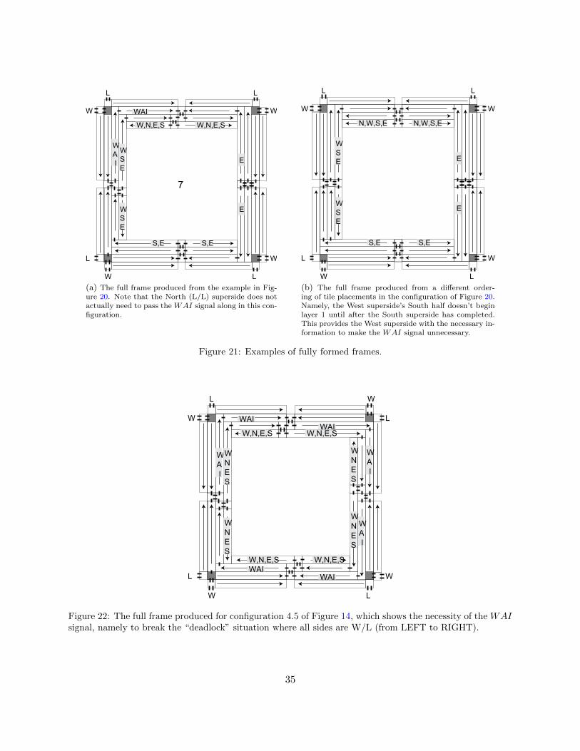
S,E
E
E
WA I
S,E
WSE
W,N,E,S
WSE
W,N,E,S
WAIW
L
W L
W
W
LL
7
(a) The full frame produced from the example in Fig-ure 20. Note that the North (L/L) superside does notactually need to pass the WAI signal along in this con-figuration.
S,E S,E
E
E
WSE
WSE
N,W,S,E N,W,S,E
W
L
W L
W
W
LL
(b) The full frame produced from a different order-ing of tile placements in the configuration of Figure 20.Namely, the West superside’s South half doesn’t beginlayer 1 until after the South superside has completed.This provides the West superside with the necessary in-formation to make the WAI signal unnecessary.
Figure 21: Examples of fully formed frames.
WA I
WAI
WA I
WAI
W,N,E,S W,N,E,S
W,N,E,S W,N,E,S
WNES
WNES
WNES
WNES
WAI
WA I
WAI
W
L
W L
W
L
WL
Figure 22: The full frame produced for configuration 4.5 of Figure 14, which shows the necessity of the WAIsignal, namely to break the “deadlock” situation where all sides are W/L (from LEFT to RIGHT).
35

ii. Each “Fast” L-half : Initiated by competition tile’s losing end, grows completely,and initiates WAI signal
iii. Each “Slow” L-half : Initiated by completed frame of adjacent superside, behavessame as non-West superside. This can occur for scenarios other than 4.5 and 4.6,depending on timing.
(c) For all D:
i. Middle:
A. WW superside: Initiates Layer 3 and passes superside info (i.e. WW )
B. LL superside: Does not initiate Layer 3 and thus doesn’t propagate (possible)WAI signal
C. WL or LW superside, and WAI signal from L: Initiates Layer 3 and passesWAI along with superside info
D. WL or LW , no WAI signal: Initiates Layer 3 and passes superside info (i.e.WL or LW )
3. Layer 3 growth:
(a) WW superside (all D): Initiated by Layer 2 middle, both halves grow and Layer 4 isinitiated from middle
(b) LL superside:
i. For D ∈ N,S,E:A. Layer 2 doesn’t pass WAI: Initiated by Layer 2 middle, both halves grow and
Layer 4 is initiated from middle
B. Layer 2 passes WAI: W-half initiated by Layer 2 and WAI is discarded, L-halfinitiated by completed frame of adjacent superside and causes placement of a“second middle” that initiates Layer 4
ii. For West superside: Both halves initiated by completed frames of adjacent sides,middle initiates Layer 4
(c) WL and LW sides:
i. For D ∈ N,S,E:A. Layer 2 doesn’t pass WAI: Initiated by Layer 2 middle, both halves grow and
Layer 4 is initiated from middle
B. Layer 2 passes WAI: W-half initiated by Layer 2 and WAI is propagated, L-half initiated by completed frame of adjacent superside and causes placementof a “second middle” that initiates Layer 4
ii. For West superside:
A. With “fast” L-half : L-half initiated by WAI from adjacent superside (if WAImakes it all the way around the frame) or by completed frame of adjacentsuperside and causes placement of a “second middle” that initiates Layer 4,W-half initiated by Layer 2 and passes WAI
B. With “slow” L-half : L-half initiated by completed frame of adjacent super-side, W-half initiated by Layer 2 (with no need to create WAI since supersideadjacent to L was able to complete)
36

4. Layer 4 growth:
(a) WW , WL or LW superside: Initiated by middle of Layer 3 and both halves completewhile copying information about all known sides from previous layer. Each end tileexposes a glue that can initiate frame growth for an adjacent superside (if it exists)while passing all known information about any sides, and if the adjacent superside isWest, the tile next to the end tile also exposes that glue.
(b) LL superside: Initiated by middle of Layer 3 and both halves complete while copyinginformation about all known sides from previous layer.
8 Probes
01101 1/1 1/0 1/1 0/1
1/00/11/11/01/1
count
generate random number and merge with glue
advertise glue and random number on two sides
1/0
10111
glue
10111
Figure 23: A probe that grows from a west superside. The probe grows to length ` = d(superside length)/2e,while copying the west glue from its base and generating a random number. Both are advertised as shown.Not shown: the probe length ` is encoded in the base of the probe as a binary sequence of O(log `) tiles.
frame
probe a base probe b base ↑↑ probe c base ↑ probe d base ↑↑
cyes
a b c d a b c d a b c d a b c d
no no
reset to c and count down to 0 again
yes
gluecount c
down to 0and check
for ↑
copy of probe table
bc
bd
ca
da
dctile types from T
Figure 24: Use of the probe table by a crawler to generate a probe region. This figure shows a crawler readingthe probe table (bottom row) in order to determine which positions in the probe region have a probe, ifthe superside is south or west. North and east supersides have simpler probe regions that simply grow oneprobe in the position corresponding to the glue on that superside. The probe table also has a position fora potential probe for a strength-τ probe (not shown for brevity), which is grown if and only if the glue hasstrength τ .
In the case that a superside wins on both ends, it attempts to contact the opposite supersidevia probes. The superside could have a glue that is either strength < τ or strength = τ . First
37

we discuss the case that the glue is strength < τ . The design of probes ensures that probes fromopposite sides meet in the middle (closing off the other two sides of the supertile from each other) ifand only if their supersides represent glues that occur on a tile type and have sufficient strength tobind it. The probes grow from a region on the superside known as the “probe region”. Each gluein T has its own unique position in the probe region; see Figure 24. The sides are not symmetric:north and east grow probes in one way, and west and south grow them in a complementary way.Suppose the glue on the north is n and the glue on the south is s. North will grow a probe in thesubregion associated with n. South will grow a probe in every subregion associated with a glueg that has the property that there is some tile type t ∈ T with g on the north, s on the south,and g and s have combined strength at least τ . Therefore, if no tile type matches glue s on thesouth and n on the north (or matches it but n and s have insufficient strength), then the north andsouth probes leave sufficiently wide gaps for crawlers to later make their way around the probes(see Figure 10). Otherwise, the probes meet in the middle of the supertile and initiate their owncrawlers (see Figure 6).
When two probes are complementary, they meet as shown in Figure 6. The probes will stop at acommon row in the middle of the supertile, with one probe staggered so that it is one tile away fromthe other. Once both probes are complete, a single tile binds between the probes. This initiatestwo crawlers, one that is intended to output the west superside (in this example), and the otherthat is intended to output the east superside. The probes also advertise the glue they represent ontheir “tip” (north edge if a southern probe, east edge if a western probe, etc.) facing one side of thesupertile, and on their side facing the other side of the supertile. This glue information is pickedup by the crawler in order to combine the two glues from each probe for the later tile lookup.
The south and west probes each generate a random number r ∈ 1, . . . |T |, which is used bythe crawlers to choose nondeterministically from among different potential output tiles during thetile lookup conducted later at the base of the probe. Since we need the two crawlers to outputsupersides that are consistent with a single tile type, the same random number is used, advertisedon each side of the south probe (or west probe, in a rotated case of Figure 6). This ensures thateach crawler will pick the same output tile type when they do their lookups.
The other reason to grow a probe is that the superside (again, south superside for concreteness)represents a strength-τ glue on a win-win frame. In this case, there is a potential problem if thenorth superside also represents a strength-τ glue on a win-win frame. If they both began to outputsupersides as in Figure 3, then if they represent different tile types, they could output glues to theeast and west that are inconsistent (not actually shared by any tile type in T ). Since we wantonly a single crawler to be responsible for outputting supersides to ensure consistency, we test forthe presence of an opposite-side strength-τ superside (with a win-win frame configuration) using aprobe. The purpose of these probes is not to cooperate, but merely to claim the “right” to fill outthe supertile.
In Figure 4, the south superside has “won” and therefore begins filling out the east side. Unlikein Figure 3, however, before it can output on the north superside, a north input superside arrives,sending its own probe to attempt to claim the right to output. It loses, but the attempt cuts offthe east from the west. Therefore, the probes use a similar cooperation as in the previous case toinitiate a second crawler from the middle of the supertile, growing counterclockwise to eventuallyoutput on the west superside. Similarly to the “across-the-gap” cooperation case described first, ifthere is more than one tile type that shares the south glue, then the random number used to chooseone of them must be the same as that used by the crawler that output on the east. Therefore the
38

probe advertises its random number on two sides, as in Figure 23.It is clear by the design of the probe table that the space between each adjacent probe is at
least Ω(|T |), so that crawlers (even two crawlers, one on top of the other) have sufficient space tocrawl around probes in the case that the probes do not meet in the middle. This is because thewidth of any crawler is O(log |T |).
The following observation is clear from the probe design described above.
Observation 8.1. Within a supertile, probes meet only if there are two opposite win-win sides andif we are simulating either (a) two-sided opposite binding for matching opposite sides or (b) twoopposite strength-τ sides.
9 Crawlers
Conceptually, crawlers are the components resembling thick bands of rows of tiles which assemblecounterclockwise around the inside edges of a supertile, gathering glue information from inputsupertiles via frame sides or probes. Each time a crawler grows along a sufficient portion of aside of a frame to read the glue information being output by the adjacent supertile, it combinesthat glue information with any it may already have acquired. It then performs a lookup on thetile lookup table that encodes the simulated tile set to see if the currently acquired set of inputglues represent a sufficient set of glues to match a tile type from the simulated set for the formingsupertile to simulate. If so, the crawler then performs the duty of outputting the necessary outputglue information along all available (non-input) sides of the supertile. If not, the crawler continuesalong an adjacent input side if it exists, or waits at a special location until and unless another inputside arrives.
9.1 Crawler initiation
A crawler can be initiated in either the corner of a frame or near the tip of a probe. We first discussthose initiated by the corners of frames.
Figure 25 shows the basic set of conventions used when talking about supertile side orientation,defining a fixed LEFT and RIGHT corner for each side and showing the counterclockwise directionof growth of crawlers. The purpose of the frame is to gather and process the information aboutexisting input sides in order to create initiation points for crawlers at exactly the corners specified bygreen arrows in the various input side and frame configurations shown in Figure 14. For shorthand,when referring to one of the configurations of Figure 14 (and its rotations), we will simply referto it as “case x.y” where x.y refers to the number in the bottom left corner of the box depictingthat configuration. The set of cases shown in Figure 14 represent the full set of possible input sidecombinations and W/L configurations for each such combination (with cases which are rotationallyequivalent omitted).
The following algorithm is implemented during frame formation, and determines whether ornot the growth of a new crawler is initiated from each side, specifically the RIGHT corner of agiven side. Crawler initiation occurs in corners created by two sides of a frame, by the placementof an initial crawler tile which uses cooperation between the two sides. Thus, each frame side must“agree” that a crawler should be initiated in that corner based on the information about its W/Lconfiguration and that of any sides it has gathered. The frame formation algorithm was specifically
39

N
E
S
W
LRL
LLR
R
R
Figure 25: Basic conventions: LEFT and RIGHT ends as defined for each superside (North, East, South,and West), and counterclockwise direction of growth of crawlers.
designed to ensure that the gathered information is sufficient to make the correct decisions for everycorner of every case.
The general rule is that if the LEFT of a side wins (is W ), then the RIGHT corner adjacentto that side will initiate a crawler. The algorithm highlights the exceptions to that rule, which arethe situations in which that rule is not followed and the crawler that would “normally” be createdfrom a corner is prevented from forming, usually by a tile from one of the frame sides not providingthe glue necessary for cooperation.
The RIGHT side corner of the D ∈ N,E, S,W side initiates a crawler if and only if:
1. D is WW or WL, unless:
(a) It’s case 4.2 (in any rotation) and D is WW . In this case, the LL side contains infor-mation about the configurations of every side, and thus will prevent the initiation of thecrawler that would normally form in the WW -LL corner.
(b) It’s case 4.5 and D is South, East, or West (all rotations of this case are the same).Therefore, in case 4.5 only the North side initiates a crawler (in the Northwest corner).All sides are WL, and the configurations of every side and thus the fact that case 4.5is encountered is known by each side of the frame (due to the transmission of the WAIsignal as discussed in the frame formation algorithm), and thus each side can place thecorrect tiles adjacent to the corners to ensure that only the North crawler begins.
2. It’s case 4.6 and D is North. Case 4.6 is the opposite of case 4.5 since all sides are LW .However, for the same general reason as in 1b, it can be guaranteed that exactly the Northside will initiate a crawler.
In addition to initiation by frame corners, crawler growth can begin on probes. In the firstsuch case, a strength-τ probe (i.e. a probe representing a glue of strength τ), if that probe wins itspoint of competition, it will initiate a crawler which will acquire the glue information and randomnumber from that probe, then grow down the counterclockwise side of the probe and then aroundthe frame. See Figure 3 for an example.
In the second case of crawler initiation by probes, two crawlers are initiated by a pair of matchingprobes which fully grow from opposite sides and meet to cooperate in the middle of the supertile, as
40

shown in Figure 6. In this case, one crawler forms on each side of the pair of now connected probes,each gathering and combining the glue information from both probes and the random number fromone (by convention, the North or West). They then both grow down the counterclockwise sides ofthe probes adjacent to them and then counterclockwise around the supertile sides.
9.2 Multiple crawlers
As seen in Figure 14, no case of frame growth results in more than 2 crawlers being initiated bythe frame. However, the cases in which 2 crawlers can arise allow for the possibility of one crawlerneeding to “piggyback” on the other. At a high level, if crawler B catches up with crawler A, it willorient itself so that it can assemble on A’s “back”, or along the surface facing the interior of thesupertile. Additionally, a crawler initiated by either a strength-τ probe or by the meeting of twomatching probes can be forced to piggyback on another crawler. Crawler A will follow crawler Buntil it is forced to halt (for instance, when A becomes full), or until A halts and B can continueand begin outputting. Sections 9.3 and 9.4 present the details of how these state transitions occur.
Also, as shown in Figure 13, it is possible for two crawlers to independently gather enough glueinformation to decide the output tile type; in particular, this happens in some four-sided bindingcases in which there are no empty output sides for one crawling to begin outputting on. In thesecases, when a crawler reaches the fourth side, it now has the frame information of all four sides.Using this information, it can determine whether there are other crawlers. If there is anothercrawler, a precedence ranking on corners is used to break symmetry; one crawler “dies” whilethe other continues gathering glue information to determine the output tile type. The (arbitrary)precedence ranking we choose is NW > SW > SE > NE. As shown in Figure 13, this results in theorange crawler continuing on to determine the output tile type, while the green crawler halts.
9.3 Crawler states
Crawlers are O(log g) tiles tall. This allows a crawler to encode up to 4 glues, along with a randomnumber n (generated by a component to be described) where 0 ≤ n < dlog ge
Every column of each crawler can be thought of as being in one of four logical states: unfilled,full, output, dead, and we consider the state of the latest column of a crawler to form to be thatcrawler’s “current” state. The crawler state is denoted by labels on each tile and this is what is usedby the supertile replacement function R (see Section 3) to map the supertile to a tile type in T . Thestate transition diagram for crawlers is shown in Figure 26, and details of those transitions follow.Additionally, the growth of crawlers into and around frame corners is depicted in Figures 28-27.These figures show how crawlers interact with the frame as well as potential piggybacking crawlers.
When a crawler is initiated and begins growth, it is considered to be unfilled. It can transitionto full only after it has gathered glues whose strengths sum to at least τ and which are consistentwith glues of a tile type from T (which may already be the case when it is initiated) and it hascompleted a tile table lookup with those glues. Once full, every column of the crawler containsthe full definition of the tile which was selected by the lookup (i.e. the encoding of the glues of its4 sides). If a full crawler encounters an empty side to which it can output, it switches its state tooutput. The other cases where it can transition from full to output involve situations where all 4adjacent supertiles formed first and provide potential input sides, and will be discussed in greaterdetail in Section 9.4.
41

In some situations, it is necessary for a crawler to permanently cease growth. This is accom-plished by a transition to state dead. Following is the list of scenarios in which a crawler transitionsto dead:
1. It is piggybacking on a crawler and grows to a point where the crawler beneath it transitionedto full
2. It grows onto a side which is WW and has enough glue information to know that the oppositeside is also WW and that the probes from those sides will meet and thus determine thesupertile’s identity. For examples, see cases 3.4 and 4.1. In both cases, crawlers will growalong an LL side and then turn onto a WW side. Since they were initiated by a WW side,they will have information about both WW sides and be able to determine whether or notthe probes from those sides will meet (which implies they have enough strength and match atile type from T ). This is performed by simultaneously performing dual lookups on the tilelookup table: one with all 3 currently collected glues and one with the 2 glues from oppositesides.
3. It arrives at a side which is WW and whose glue strength is τ , which means that either thatside or the opposite side which may also have a τ -strength glue will initiate the necessarycrawlers to complete the supertile.
4. It gathers 4 potential input glues but there is no matching tile from T
5. If a crawler gathers 4 potential input glues and is piggybacking on a crawler with a higherprecedence, where the precedence order is NW > SW > SE > NE. This situation can occurin cases 4.1, 4.2, and 4.4. By one crawler halting it is ensured that in these cases exactly onecrawler changes state to output and thus determines the supertile’s identity.
9.4 Outputting crawlers
In this section, we discuss how a full crawler can change states to output and thus determine theidentity of the forming supertile. In all situations other than those in which crawlers are initiatedby matching probes meeting in the center of the supertile (which is possible in cases 2.1, 3.4, and4.1), exactly one crawler changes state to output. In the cases of matching probes there will beexactly 2 such crawlers, but they will have both shared the output of a single random numberselection and are thus guaranteed to make the same selection of supertile identity. Also note that,due to the location of the probes, those two crawlers will be completely isolated from each otherand thus unable to encounter or crawl over each other.
The transition from full to output (note that only a full crawler can transition output) canoccur in 3 general situations:
1. When a full crawler reaches a frame corner where the adjacent side has not formed, signifyingthat there may not be an adjacent supertile there and thus that side should serve as an outputside of the forming supertile. If the crawler is able to win POC2 (as shown in Figure 29), ittransitions to output and begins the process of outputting the superside (described below).
2. In the case where the crawler has failed to win all POC2’s due to the existence of all 4 framesides, and it determines that no other crawler will have higher precedence (See item 5 inSection 9.3 for more details.)
42

crawler initiation
found matching tile intile lookup table
1. piggybacking on full crawler2. determined probes meeting in middle will block it3. determined -strength probe will be in front of it3. there's 4 supersides but there's no matching tile4. there's 4 supersides but there's a crawler with higher precedence
1. p
iggyb
ackin
g on
fu
ll cra
wler a
nd th
ere's
< 4
supe
rside
s
2. th
ere's
4 su
pers
ides
bu
t the
re's
a cr
awler
with
high
er p
rece
denc
e
1 claimed POC2 for a superside2 there's four supersides, and there's no other crawler with higher precedence that will eventually transition to output
Figure 26: Definition of state transitions for crawlers. A state change occurs if any of the edge labels aresatisfied. A crawler’s state determines whether it has encountered sufficient glue strength to output a tiletype, and also whether it has actually taken responsibility for determining the output tile type (which it willnot if another crawler exists that takes responsibility).
Full/Output ge
geOutput initiation row
POC2
POC1
Outputting crawler (paused)
a
Full/Output ge
ge
POC1
POC2
b
Full/Output
c
Full ge
ge
POC1
POC2
Output
Figure 27: Three possible scenarios for a full/output crawler meeting a frame. (a) A crawler in either ofstates full/output that wants to produce an east output superside arrives at an empty east superside, (i.e.it claims POC1 and POC2, see Figure 30a for more details) and initiates outputting on the east. If thecrawler was previously in state full it transitions to state output. Once it has output the east glue, it mustpause until additional output information arrives from its left. (b) A crawler in either of states full/outputthat wants to produce an east output superside arrives at a non-empty east superside (i.e. it claims POC1,fails to claim POC2), which triggers growth of the crawler to the north. The crawler does not change state.It continues on its journey to find an empty north superside to place output. (c) A crawler in state full
that wants to place output at a single superside to the east (after this it has no more output supersides toproduce). However, the crawler arrives at a non-empty east superside (i.e. it claims POC1, fails to claimPOC2). The crawler transitions to state output and outputs a single column of O(log g) tiles.
43

Unfilled
Unfilled
POC1
Unfilled
Unfilled
ge
ge
POC1
Unfilled ge
ge
POC1
gs
ge
a b c
Figure 28: Three scenarios of crawlers arriving at frame corners. (a) A single, unfilled crawler arrives at thelocation which is the width of one crawler away from the corner. It then grows a single row of tiles, each ofwhich cooperates with the frame below in order to pass the glue information from the frame to its top side,toward “point of competition 1” (POC1). The crawler loses POC1 as the right side of the frame is fullyformed and initiates growth of a new crawler (following the crawler initiation protocol in Section 9.1). Thenewly formed crawler provides the cooperation necessary for the continuation of the first crawler. (b) Anunfilled crawler and a piggybacking unfilled crawler near the corner. Since there are already 2 crawlers, it isguaranteed that no other crawler can be initiated and therefore the bottom crawler will win POC1. At thispoint, since both crawlers are unfilled the growth of both will pause until and unless the frame’s right sidecompletes. (c) If and when the frame’s right side arrives, the 2 positions immediately above POC1 will betiled utilizing cooperation from below and the right, ensuring that there is another input side for the crawlerto collect (possibly allowing it to become full) and initiating the growth of the rows back toward the crawlerwhich will result in its rotation and growth upward. (The need for 2 such rows is shown in Figure 29.) Notethat the growth of the bottom crawler in this scenario is the same whether or not there is a piggybackingcrawler.
3. In the case of 4-sided binding (where all 4 potential input sides actually serve as input sides toa simulated tile which would bind on all sides), once a crawler has acquired glue informationabout all 4 sides and determines that no other crawler will have a higher precedence
Recall that once a crawler transitions to output, every column then contains the full definitionof the tile selected by the lookup along with a special marker to denote that that crawler is nowin state output and contains the definitive output of the tile lookup and therefore the identifyof the forming supertile. In fact, in situations where 4 potential input supersides exist, once thecorrect crawler transitions to output, it simply “prints” the definition of the selected tile on a singlecolumn of tiles and ceases growth. This provides the representation function with the necessaryinformation to map the supertile to a tile from T .
When a crawler wins POC2 for a side, it begins the process of creating an output superside.A portion of this process is depicted in Figure 29(c). In order to do this, it begins the assemblyof a row of tiles, known as the output initiation row, which grow back along the top surface of thecrawler until reaching the representation of the tile lookup table which was passed upward throughthe growing crawler. Once arriving there, this row provides the cooperation necessary for the tilelookup and probe tables to grow upward and rotate into positions necessary to grow toward theside being output. Upon arriving next to the outputting crawler, which can’t continue growth untilthose tables arrive, they provide the cooperation necessary for the crawler to advance and also pass
44

Unfilled
Full
ge
ge
Output initiation row
POC2
POC1
Outputting crawler (paused)
Unfilled
Full
ge
ge
POC1
POC2
a b
Full/Output ge
ge
POC2
POC1
Outputting crawler
c
tile lookup table
tilelookuptable
Output initiation row
Figure 29: Two additional scenarios of crawlers arriving at frame corners. (a) The bottom crawler (which inthis scenario can only be unfilled because if it was full the top crawler would have halted) arrives near thecorner and wins POC1 (which it must be able to do since there are already 2 crawlers). The piggybackingcrawler is full and begins a path towards POC2 which, if won, would allow it to begin outputting. If the pathis blocked at any point by the arrival of the frame’s right side, the completion of that frame side will providethe necessary cooperation for the third row which allows both crawlers to rotate and continue upward. (b) Ifthe top crawler’s path to POC2 succeeds in winning POC2, it is guaranteed to be able to grow a return pathwhich is unblocked and can initiate the transition of the top crawler to outputting. (See Figure 30b for moredetails.) (c) A crawler which wins POC2 and begins outputting sends an “output initiation row” across itstop, back toward the center. When this row reaches the representation of the tile lookup table which waspassed up through the crawler previously, it initiates growth that brings the tile lookup table and probetable upward. The definitions of those tables rotate as necessary to allow them to grow toward the side(s)being output. Once they arrive in position next to the outputting crawler, they provide the cooperationnecessary for the crawler to continue growing, and also outputting the values of those tables. See Figure 3for more details on the paths of growth of those tables.
the table encodings through to the output superside.Note that the growth of the output initiation row is guaranteed never to be blocked by the
presence of a piggybacking crawler (although climbing over it wouldn’t necessarily be problematic),since the only time that a piggybacking crawler continues growth along the back of a full crawleris in situations where there are 4 potential input supersides, and thus no output initiation row ispossible. In other piggybacking scenarios, the bottom crawler transitions to full on the Left end ofa superside, which is therefore where the piggybacking crawler would decide to transition to dead
and cease growth, while a possible output initiation row would be initiated from the Right end andnot need to grow back all the way to the halted piggybacking crawler.
10 The tile lookup table
The tile lookup table is composed of a row of tiles that encode T , in a way to be discussed, andleave space necessary for particular computations during the lookup process. This table is usedby a crawler that grows across its surface reading the information encoded there and utilizinginformation about the supertile’s input glues (those it has already gathered) to find a table entrycorresponding to a tile type t ∈ T that has those same glues. If such an entry is found, the crawlerextracts and encodes the definition of t and switches its state to full. If no such entry is found,the crawler preserves its encoding of collected input glues and remains in state unfilled.
45

a b c d(a) A set of examples displaying possible growth sequencesinvolving a point of competition, a.k.a. POC, (purple) be-tween a crawler (grey) growing from the left into a framecorner which could potentially initiate the growth of acrawler (from the bottom, growing upward) All growth issequential from bottom to top. (a) Crawler grows bottomrow to POC, wins location, then grows second row backto initiate continued crawler growth. (b) New crawler isinitiated by frame corner winning the POC. A second rowgrows above the first for symmetry (both of which com-pletely form), then the new crawler begins growth withglue information from bottom and right. (c) The framecorner wins the POC, but the crawler grows a partial row.(d) The second row, initiated by the corner, covers bothhalves of the first row, propagating the information fromthe bottom upward and allowing the new crawler to grow.
31 2
4 5 6
4 3 2 1
3POC1 POC2(b) Depiction of a portion of the path grown froma piggybacking crawler to POC2. The numbersacross the top show the numbers of the frame lay-ers for the east side frame, the arrows below themshow the possible growth direction(s) of each row,and the numbers within tiles show the ordering oftile placements forming the row to POC2, whichis the labeled 6. Tiles 4, 5, and 6 utilize co-operation with tiles below, which allows themto propagate the necessary information to theirnorth sides which can allow the frame to grownormally if the row does not make it to POC2but is blocked by an existing partial frame. Notethat since layer 4 always grows from the centerto the corner, there is no information lost if tiles2 and 3 are placed but then the frame side forms.Finally, if POC2 is reached and won by the path,then the only tiles that could possibly be placedby a growing frame half are those in the 3 posi-tions directly below POC2, and thus the returnrow which grows back to the crawler can formunblocked.
Figure 30: Points of competition between crawlers and frames.
10.1 Tile lookup table structure
Let G be the set of all glues on tiles in T plus the null glue, and g = |G| be the count of those glues.Assign the elements of G a fixed ordering with the null glue at index 0, and for x ∈ G let bin(x)be the binary encoding of x’s index in G, padded to dlog ge bits. Let bin(x)i for 0 ≤ i < dlog gerepresent the ith bit of bin(x). An address A is a string of hexadecimal characters of length dlog ge,which is a combination of bin(a), bin(b), bin(c), bin(d) for a, b, c, d ∈ G such that the ith positionof A, Ai for 0 ≤ i < dlog ge, is the hexadecimal value of the bit string bin(a)ibin(b)ibin(c)ibin(d)i.We can denote such an address as Aa,b,c,d to show the glues composing it and their ordering. Byconvention, the glues composing an address are assumed to be those of the sides of a tile orderedNorth, East, South, West. The absence of a glue (representing a missing side; note that this isdifferent from the null glue) is represented by a null glue when doing a table lookup.
There are g4 possible addresses for tiles in T (i.e. every possible combination and ordering offour glues from G). The purpose of the entries in the tile lookup table is to list the set of tiles fromT that are consistent with each possible set of input sides to the supertile whose glue strengthssum to at least τT . Therefore, it is possible for each tile to map to several addresses. In fact, foreach t ∈ T , for every subset of glues on t whose strengths sum to at least τT , t is validly addressedby every address that is composed of at least those glues on the sides on which they appear on t.
These addresses are “accessed” by crawlers by means of counters; if a tuple of glues (binarystrings) whose concatenation represents an integer k, then by counting (once per entry) from kdown to 0, a crawler can determine the location of the entry relevant to it. Most crawlers doonly a single lookup, but one situation requires doing two lookups at the same time, illustrated in
46

Figure 8. In this case, the green crawler must do a standard look up corresponding to its threeglues from the north, west, and south. However, it must simultaneously perform a lookup usingonly the north and south glues, to check whether the north and south probes will meet (halting ifso). These two lookups can be performed simultaneously by running two independent counters inparallel as the crawler moves over the lookup table.
random num selection # # # #bin(tile a) bin(tile b) bin(tile e) bin(tile b). #
0 1 2 3 4
address entries0 0 1 0
#
0 1 2 3 4
#1 # 2 # 1 #
address entry counts
address entries
a,sa,0 0,sa,c a,c,0 a,e,0 0,e,0 0,0,0 t
countdowna to 0
0,0,t0,sa,0
get c
select random ebetween 0 and c
move sa to a and create e = 0
countdowna to 0
countdowne to 0
get t switch to
outputting t
n-1
1
0
n-1
1
0
n-1
1
0
n-1
1
0
n-1
1
0
n-1
1
0
n-1
1
0
n-1
1
0
n-1
1
0
create t = 0
tile lookup table
crawleraddresses
compute state
t*
n-1
1
0
Figure 31: The tile lookup table (bottom row) and depiction of the front column of a crawler growing overit and performing a tile lookup.
The general structure of the tile lookup table for a trivial example is shown in Figure 31 asthe bottom row of tiles. The main sections of the table are the “address entry counts”, “randomnumber selection”, “address entries”, and “compute state”.
Address entry counts This section (the leftmost) of the tile lookup table consists of g4 tileswith “#” symbols on their tops - one for every address, representing those addresses in order from0 to g4 − 1. For each address A, if n tiles from T are validly addressed by A, then the binaryencoding of n is represented by the dlog ne tiles immediately to the right of the Ath #, which isfollowed immediately by the (A+ 1)th #. If n = 0 there are no tiles between those #’s.
Random number selection This section of the tile lookup table conveys no information on thetop of tiles, but instead consists of a series of tiles that provide the spacing necessary for the crawlerto perform the function of random number generation. Since there can be multiple entries for theaddress being looked up and exactly one of them must be selected, and it is also important tofairly choose between them, it is necessary to (approximately) uniformly select a random numberto perform that selection. Since there is the requirement that the space used for random numbergeneration be bounded (so it can’t require assembly growth that collides with other portions of thesupertile or grows outside of the m×m square), it is impossible to guarantee a perfectly uniformdistribution for the random number selection (see [21] for details). However, in [21] the authorspresented a number of modular tile sets that can be used to select random numbers while providingvarying degrees of uniformity (with tradeoffs in the amount of space required), and for the randomnumber selection component of the crawler it is possible to choose any of those tile sets. The resultof the computation is the selection of a value e where 0 ≤ e < n, representing the address entryto be selected. Note that if a crawler is initiated by a probe, rather than the corner of a frame,the random number selection is performed by the probe so that the same random selection can beutilized by both of the crawlers that will grow into opposite sides of the supertile. In this case, a
47

random number r where 0 ≤ r < g is contained within the crawler before it reaches the tile lookuptable, and in this section of the table the computation that is performed is e = r%n. Note thatsince r < g, O(log g) bits are required to represent r.
Address entries Similar to the “address entry counts” section, this section (the rightmost) ofthe tile lookup table consists of one tile representing a “#” symbol for every address, representingthose addresses in order from 0 to g4−1. For each address A, if n tiles from T are validly addressedby A, then there are n entries, each separated by a tile with a “.” symbol. Each entry consists ofthe address (which fully specifies the tile type) of one of those validly addressed tiles.
Compute state This section of the tile lookup table conveys no information on the top of itstiles, but instead consists of a sequence of spacer tiles that provide enough spacing for the crawlerto perform the function of computing its (possibly new) state after having performed a tile lookup.The full set of state changes that can occur are shown in Section 9.3, and this computation isperformed by a (constant sized) modular tile set that utilizes information gathered by the crawlerrelated to: the number and W/L configuration of potential input sides, the result of the tile tablelookup, and the crawler’s initiation number (as defined in Section 9.3). The state change is realizedby the columns of the crawler forming from tiles specific to the new state, and in some cases acrawler may effectively transition from unfilled to output by making two quick transitions: firstforming a column in state full, then the next in output.
10.2 Example
Figure 31 shows an example of a crawler growing across the top of a tile lookup table from left toright, with each vertical column representing the front of the crawler at a particular point. Theinitial column of the crawler contains two copies of the address for the combination of input sidesthat have been collected by the crawler, represented as a and sa, with the n hexadecimal valuepositions of each represented by n positions from bottom to top with the least significant positionat the bottom. As the crawler grows to the right, across the “address entry counts” section, thevalue of a is decremented each time a position representing a “#” is encountered. Once a reaches0, the correct address location has been reached and the following string of bits (which representsthe number of entries for that address) is rotated upward into the crawler (occupying the positionshown as c that was initially filled with 0’s). The crawler then grows to the section for randomnumber selection where the value of sa is moved to the position for a and a position for number eis initialized to 0 before the crawler performs a random number selection between 0 and c. Next,the crawler once again counts a down to 0. At that point, it counts e down to 0, after which ithas arrived at the appropriate entry of the correct address. The definition of the matching tile t isrotated upward into the crawler and the crawler grows toward the section for state computation.Finally, following the rules of crawler state transition as shown in Section 9.3, it can potentiallychange state, which consists of utilizing different sets of tiles marked with those states (if it continuesgrowth forward).
10.3 Scale
The size of the tile lookup table dominates the size of a supertile and is therefore the main factorin the scaling factor m. There are g4 addresses, falling into each of the following categories:
48

1. 1 address has 4 null glues and contains 0 entries
2. 4(g − 1) addresses have exactly 1 non-null glue, and each such address can contain at mostg3 entries, totalling 4g4 − 4g3 entries
3. 6(g− 1)2 addresses have exactly 2 non-null glues, and each such address can contain at mostg2 entries, totalling 6g4 − 12g3 + 6g2 entries
4. 4(g− 1)3 addresses have exactly 3 non-null glues, and each such address can contain at mostg entries, totalling 4g4 − 12g3 + 12g2 − 4g entries
5. (g − 1)4 addresses have 4 non-null glues, and each such address can contain exactly 1 entry,totalling g4 − 4g3 + 6g2 − 4g + 1 entries
This yields a maximum possible 15g4 − 32g3 + 24g2 − 8g + 1 entries. Each entry in the “addressentries” section requires log g space, for a total space requirement of O(g4 log g), and since thissection is the largest in the tile lookup table, the overall size is O(g4 log g). In order to allow forcrawlers to grow over the top of a tile lookup table and read the encoded information while alsoperforming computations based on that information, it is necessary for the columns of a crawler tobe able to grow in a zig-zag manner, growing one column from the bottom to top, then the nextfrom the top to bottom. This means that only the tiles of every other column cooperate with thoseof the lookup table and thus read its information. Therefore, the tile lookup table actually consistsof “spacer” tiles in every other position and is thus twice as wide as previously mentioned, but thatdoubling factor does not change the O(g4 log g) bound.
A Abstract Tile Assembly Model
This section gives a terse definition of the abstract Tile Assembly Model (aTAM, [48]). This is nota tutorial; for readers unfamiliar with the aTAM, [41] gives an excellent introduction to the model.
Fix an alphabet Σ. Σ∗ is the set of finite strings over Σ. Z, Z+, and N denote the set of integers,positive integers, and nonnegative integers, respectively. Given A ⊆ Z2, the full grid graph of A isthe undirected graphGf
A = (V,E), where V = A, and for all u, v ∈ V , u, v ∈ E ⇐⇒ ‖u−v‖2 = 1;i.e., iff u and v are adjacent on the integer Cartesian plane.
A tile type is a tuple t ∈ (Σ∗×N)4; i.e., a unit square with four sides listed in some standardizedorder, each side having a glue g ∈ Σ∗×N consisting of a finite string label and nonnegative integerstrength. We assume a finite set T of tile types, but an infinite number of copies of each tiletype, each copy referred to as a tile. An assembly is a nonempty connected arrangement of tileson the integer lattice Z2, i.e., a partial function α : Z2 99K T such that Gf
dom α is connected anddom α 6= ∅. Let AT denote the set of all assemblies of tiles from T , and let AT<∞ denote the setof finite assemblies of tiles from T . The shape Sα ⊆ Z2 of α is dom α. Two adjacent tiles in anassembly interact if the glues on their abutting sides are equal (in both label and strength) andhave positive strength. Each assembly α induces a binding graph Gb
α, a grid graph whose verticesare positions occupied by tiles, with an edge between two vertices if the tiles at those verticesinteract.8 Given τ ∈ Z+, α is τ -stable if every cut of Gb
α has weight at least τ , where the weightof an edge is the strength of the glue it represents. That is, α is τ -stable if at least energy τ is
8For GfSα
= (VSα , ESα) and Gbα = (Vα, Eα), Gb
α is a spanning subgraph of GfSα
: Vα = VSα and Eα ⊆ ESα .
49

required to separate α into two parts. When τ is clear from context, we say α is stable. Given twoassemblies α, β : Z2 99K T , we say α is a subassembly of β, and we write α v β, if Sα ⊆ Sβ and, forall points p ∈ Sα, α(p) = β(p).
A tile assembly system (TAS) is a triple T = (T, σ, τ), where T is a finite set of tile types,σ : Z2 99K T is the finite, τ -stable seed assembly, and τ ∈ Z+ is the temperature. Given twoτ -stable assemblies α, β : Z2 99K T , we write α→T1 β if α v β and |Sβ \Sα| = 1. In this case we sayα T -produces β in one step.9 If α →T1 β, Sβ \ Sα = p, and t = β(p), we write β = α + (p 7→ t).The T -frontier of α is the set ∂T α =
⋃α→T1 β
Sβ \ Sα, the set of empty locations at which a tilecould stably attach to α.
A sequence of k ∈ Z+∪∞ assemblies α0, α1, . . . is a T -assembly sequence if, for all 1 ≤ i < k,αi−1 →T1 αi. We write α →T β, and we say α T -produces β (in 0 or more steps) if there is a T -assembly sequence α0, α1, . . . of length k = |Sβ \ Sα|+ 1 such that 1) α = α0, 2) Sβ =
⋃0≤i<k Sαi ,
and 3) for all 0 ≤ i < k, αi v β. If k is finite then it is routine to verify that β = αk−1.10 We sayα is T -producible if σ →T α, and we write A[T ] to denote the set of T -producible assemblies. Therelation →T is a partial order on A[T ] [33, 40]. A T -assembly sequence α0, α1, . . . is fair if, for alli and all p ∈ ∂T αi, there exists j such that αj(p) is defined; i.e., no frontier location is “starved”.
An assembly α is T -terminal if α is τ -stable and ∂T α = ∅. We write A[T ] ⊆ A[T ] todenote the set of T -producible, T -terminal assemblies. A TAS T is directed (a.k.a., deterministic,confluent) if the poset (A[T ],→T ) is directed; i.e., if for each α, β ∈ A[T ], there exists γ ∈ A[T ]such that α→T γ and β →T γ.11
When T is clear from context, we may omit T from the notation above and instead write →1,→, ∂α, frontier, assembly sequence, produces, producible, and terminal. We make the followingassumptions that do not affect the fundamental capabilities of the model, but which will simplifyour main construction. Since the behavior of a TAS T = (T, σ, τ) is unchanged if every glue withstrength greater than τ is changed to have strength exactly τ , we assume henceforth that all gluestrengths are in the set 0, 1, . . . , τ. We assume that glue labels are never shared between gluesof unequal strength.
Acknowledgement
We would like to thank Matthew Cook for pointing out a simplification to our construction.
References
[1] Zachary Abel, Nadia Benbernou, Mirela Damian, Erik D. Demaine, Martin Demaine, RobinFlatland, Scott Kominers, and Robert Schweller, Shape replication through self-assembly and
9Intuitively α→T1 β means that α can grow into β by the addition of a single tile; the fact that we require both αand β to be τ -stable implies in particular that the new tile is able to bind to α with strength at least τ . It is easy tocheck that had we instead required only α to be τ -stable, and required that the cut of β separating α from the newtile has strength at least τ , then this implies that β is also τ -stable.
10If we had defined the relation→T based on only finite assembly sequences, then→T would be simply the reflexive,transitive closure (→T1 )∗ of →T1 . But this would mean that no infinite assembly could be produced from a finiteassembly, even though there is a well-defined, unique “limit assembly” of every infinite assembly sequence.
11The following two convenient characterizations of “directed” are routine to verify. T is directed if and only if|A[T ]| = 1. T is not directed if and only if there exist α, β ∈ A[T ] and p ∈ Sα ∩ Sβ such that α(p) 6= β(p).
50

RNase enzymes, SODA 2010: Proceedings of the Twenty-first Annual ACM-SIAM Symposiumon Discrete Algorithms (Austin, Texas), Society for Industrial and Applied Mathematics, 2010.
[2] Leonard M. Adleman, Qi Cheng, Ashish Goel, and Ming-Deh Huang, Running time and pro-gram size for self-assembled squares, STOC 2001: Proceedings of the thirty-third annual ACMSymposium on Theory of Computing (Hersonissos, Greece), ACM, 2001, pp. 740–748.
[3] Leonard M. Adleman, Qi Cheng, Ashish Goel, Ming-Deh Huang, and Hal Wasserman, Linearself-assemblies: Equilibria, entropy and convergence rates, In Sixth International Conferenceon Difference Equations and Applications, Taylor and Francis, 2001.
[4] Leonard M. Adleman, Qi Cheng, Ashish Goel, Ming-Deh A. Huang, David Kempe, Pablo Mois-set de Espanes, and Paul W. K. Rothemund, Combinatorial optimization problems in self-assembly, STOC 2002: Proceedings of the Thirty-Fourth Annual ACM Symposium on Theoryof Computing, 2002, pp. 23–32.
[5] Leonard M. Adleman, Jarkko Kari, Lila Kari, Dustin Reishus, and Petr Sosık, The undecidabil-ity of the infinite ribbon problem: Implications for computing by self-assembly, SIAM Journalon Computing 38 (2009), no. 6, 2356–2381, Preliminary version appeared in FOCS 2002.
[6] Gagan Aggarwal, Qi Cheng, Michael H. Goldwasser, Ming-Yang Kao, Pablo Moisset de Es-panes, and Robert T. Schweller, Complexities for generalized models of self-assembly, SIAMJournal on Computing 34 (2005), 1493–1515, Preliminary version appeared in SODA 2004.
[7] Florent Becker, Ivan Rapaport, and Eric Remila, Self-assembling classes of shapes with a mini-mum number of tiles, and in optimal time, FSTTCS 2006: Foundations of Software Technologyand Theoretical Computer Science, 2006, pp. 45–56.
[8] Nathaniel Bryans, Ehsan Chiniforooshan, David Doty, Lila Kari, and Shinnosuke Seki, Thepower of nondeterminism in self-assembly, SODA 2011: Proceedings of the 22nd Annual ACM-SIAM Symposium on Discrete Algorithms, SIAM, 2011, pp. 590–602.
[9] Sarah Cannon, Erik D. Demaine, Martin L. Demaine, Sarah Eisenstat, Matthew J. Patitz,Robert Schweller, Scott M. Summers, and Andrew Winslow, Two hands are better than one(up to constant factors), Arxiv preprint arXiv:1201.1650 (2012).
[10] Eric Goles Ch., Cedric Little, and Ivan Rapaport, Understanding a non-trivial cellular au-tomaton by finding its simplest underlying communication protocol, ISAAC 2008, The 19thInternational Symposium on Algorithms and Complexity, Lecture Notes in Computer Science,vol. 5369, 2008, pp. 592–604.
[11] Eric Goles Ch., Pierre-Etienne Meunier, Ivan Rapaport, and Guillaume Theyssier, Commu-nication complexity and intrinsic universality in cellular automata, Theor. Comput. Sci. 412(2011), no. 1-2, 2–21.
[12] Harish Chandran, Nikhil Gopalkrishnan, and John H. Reif, The tile complexity of linear as-semblies, ICALP 2009: 36th International Colloquium on Automata, Languages and Program-ming, vol. 5555, Springer, 2009, pp. 235–253.
51

[13] Ho-Lin Chen and David Doty, Parallelism and time in hierarchical self-assembly, SODA 2012:Proceedings of the 23rd Annual ACM-SIAM Symposium on Discrete Algorithms, SIAM, 2012.
[14] Ho-Lin Chen, David Doty, and Shinnosuke Seki, Program size and temperature in self-assembly,ISAAC 2011: Proceedings of the 22nd International Symposium on Algorithms and Compu-tation, Lecture Notes in Computer Science, vol. 7074, Springer-Verlag, 2011, pp. 445–453.
[15] Matthew Cook, Yunhui Fu, and Robert T. Schweller, Temperature 1 self-assembly: Determin-istic assembly in 3d and probabilistic assembly in 2d, SODA, 2011, pp. 570–589.
[16] Marianne Delorme, Jacques Mazoyer, Nicolas Ollinger, and Guillaume Theyssier, Bulking II:Classifications of cellular automata, Theor. Comput. Sci. 412 (2011), no. 30, 3881–3905.
[17] Erik D. Demaine, Martin L. Demaine, Sandor Fekete, Matthew J. Patitz, Robert Schweller,Andrew Winslow, and Damien Woods, One tile to simulate any tile system, Preprint (2012).
[18] Erik D. Demaine, Martin L. Demaine, Sandor P. Fekete, Mashhood Ishaque, Eynat Rafalin,Robert T. Schweller, and Diane L. Souvaine, Staged self-assembly: Nanomanufacture of arbi-trary shapes with O(1) glues, Natural Computing 7 (2008), no. 3, 347–370, Preliminary versionappeared in DNA 13.
[19] Erik D. Demaine, Matthew J. Patitz, Robert T. Schweller, and Scott M. Summers, Self-assembly of arbitrary shapes using RNase enzymes: Meeting the Kolmogorov bound with smallscale factor, STACS 2011: Proceedings of the 28th International Symposium on TheoreticalAspects of Computer Science, 2011.
[20] David Doty, Randomized self-assembly for exact shapes, SIAM Journal on Computing 39(2010), no. 8, 3521–3552, Preliminary version appeared in FOCS 2009.
[21] David Doty, Jack H. Lutz, Matthew J. Patitz, Scott M. Summers, and Damien Woods, Ran-dom number selection in self-assembly, UC 2009: Proceedings of The Eighth InternationalConference on Unconventional Computation, Lecture Notes in Computer Science, vol. 5715,Springer, 2009, pp. 143–157.
[22] , Intrinsic universality in self-assembly, STACS 2010: Proceedings of The Twenty-Seventh International Symposium on Theoretical Aspects of Computer Science, Leibniz Inter-national Proceedings in Informatics (LIPIcs), vol. 5, 2010, pp. 275–286.
[23] David Doty, Matthew J. Patitz, Dustin Reishus, Robert T. Schweller, and Scott M. Summers,Strong fault-tolerance for self-assembly with fuzzy temperature, FOCS 2010: Proceedings of the51st Annual IEEE Symposium on Foundations of Computer Science, IEEE, 2010, pp. 417–426.
[24] B. Durand and Zs. Roka, The game of life: universality revisited, Cellular Automata (M. De-lorme and J. Mazoyer, eds.), Kluwer, 1999.
[25] Kenichi Fujibayashi, Rizal Hariadi, Sung Ha Park, Erik Winfree, and Satoshi Murata, Towardreliable algorithmic self-assembly of DNA tiles: A fixed-width cellular automaton pattern, NanoLetters 8 (2007), no. 7, 1791–1797.
[26] D. Han, S. Pal, J. Nangreave, Z. Deng, Y. Liu, and H. Yan, DNA origami with complexcurvatures in three-dimensional space, Science 332 (2011), no. 6027, 342.
52

[27] Y. He, T. Ye, M. Su, C. Zhang, A.E. Ribbe, W. Jiang, and C. Mao, Hierarchical self-assemblyof DNA into symmetric supramolecular polyhedra, Nature 452 (2008), no. 7184, 198–201.
[28] Ming-Yang Kao and Robert T. Schweller, Reducing tile complexity for self-assembly throughtemperature programming, SODA 2006: Proceedings of the 17th Annual ACM-SIAM Sympo-sium on Discrete Algorithms, 2006, pp. 571–580.
[29] , Randomized self-assembly for approximate shapes, ICALP 2008: International Collo-qium on Automata, Languages, and Programming (Luca Aceto, Ivan Damgard, Leslie AnnGoldberg, Magnus M. Halldrsson, Anna Ingolfsdottir, and Igor Walukiewicz, eds.), LectureNotes in Computer Science, vol. 5125, Springer, 2008, pp. 370–384.
[30] Gregory Lafitte and Michael Weiss, Universal tilings, STACS 2007, 24th Annual Symposiumon Theoretical Aspects of Computer Science, Aachen, Germany, February 22-24, 2007, Pro-ceedings (Wolfgang Thomas and Pascal Weil, eds.), Lecture Notes in Computer Science, vol.4393, Springer, 2007, pp. 367–380.
[31] , Simulations between tilings, Tech. report, University of Athens, 2008.
[32] , An almost totally universal tile set, Theory and Applications of Models of Computa-tion, 6th Annual Conference, TAMC 2009, Changsha, China, May 18-22, 2009. Proceedings(Jianer Chen and S. Barry Cooper, eds.), Lecture Notes in Computer Science, vol. 5532,Springer, 2009, pp. 271–280.
[33] James I. Lathrop, Jack H. Lutz, and Scott M. Summers, Strict self-assembly of discrete Sierpin-ski triangles, Theoretical Computer Science 410 (2009), 384–405, Preliminary version appearedin CiE 2007.
[34] Kyle Lund, Anthony T. Manzo, Nadine Dabby, Nicole Micholotti, Alexander Johnson-Buck,Jeanetter Nangreave, Steven Taylor, Renjun Pei, Milan N. Stojanovic, Nils G. Walter, ErikWinfree, and Hao Yan, Molecular robots guided by prescriptive landscapes, Nature 465 (2010),206–210.
[35] Jan Manuch, Ladislav Stacho, and Christine Stoll, Step-assembly with a constant number oftile types, ISAAC 2009: Proceedings of the 20th International Symposium on Algorithms andComputation (Berlin, Heidelberg), Springer-Verlag, 2009, pp. 954–963.
[36] Nicolas Ollinger, Intrinsically universal cellular automata, CSP, 2008, pp. 199–204.
[37] Matthew J. Patitz, Simulation of self-assembly in the abstract tile assembly model with ISUTAS, FNANO 2009: 6th Annual Conference on Foundations of Nanoscience: Self-AssembledArchitectures and Devices (Snowbird, Utah, USA, April 20-24 2009), Sciencetechnica, 2009,pp. 209–219.
[38] L. Qian and E. Winfree, Scaling up digital circuit computation with DNA strand displacementcascades, Science 332 (2011), no. 6034, 1196.
[39] L. Qian, E. Winfree, and J. Bruck, Neural network computation with dna strand displacementcascades, Nature 475 (2011), no. 7356, 368–372.
53

[40] Paul W. K. Rothemund, Theory and experiments in algorithmic self-assembly, Ph.D. thesis,University of Southern California, December 2001.
[41] Paul W. K. Rothemund and Erik Winfree, The program-size complexity of self-assembledsquares (extended abstract), STOC 2000: Proceedings of the Thirty-Second Annual ACMSymposium on Theory of Computing, 2000, pp. 459–468.
[42] Paul W.K. Rothemund, Nick Papadakis, and Erik Winfree, Algorithmic self-assembly of DNASierpinski triangles, PLoS Biology 2 (2004), no. 12, 2041–2053.
[43] PW Rothemund, Folding DNA to create nanoscale shapes and patterns, Nature 440 (2006),no. 7082, 297–302.
[44] Nadrian C. Seeman, Nucleic-acid junctions and lattices, Journal of Theoretical Biology 99(1982), 237–247.
[45] David Soloveichik and Erik Winfree, Complexity of self-assembled shapes, SIAM Journal onComputing 36 (2007), no. 6, 1544–1569, Preliminary version appeared in DNA 10.
[46] Scott M. Summers, Reducing tile complexity for the self-assembly of scaled shapes throughtemperature programming, Algorithmica, to appear.
[47] Hao Wang, Proving theorems by pattern recognition – II, The Bell System Technical JournalXL (1961), no. 1, 1–41.
[48] Erik Winfree, Algorithmic self-assembly of DNA, Ph.D. thesis, California Institute of Technol-ogy, June 1998.
[49] Erik Winfree, Furong Liu, Lisa A. Wenzler, and Nadrian C. Seeman, Design and self-assemblyof two-dimensional DNA crystals., Nature 394 (1998), no. 6693, 539–44.
[50] B. Yurke, A.J. Turberfield, A.P. Mills Jr, F.C. Simmel, and J.L. Neumann, A DNA-fuelledmolecular machine made of DNA, Nature 406 (2000), no. 6796, 605–608.
54