Embed Size (px)
Citation preview
TRANSACTIONS OF THE INSTITUTE OF FLUID-FLOW MACHINERY
No. 129, 2015, 51–75
PAWEŁ ZIÓŁKOWSKIa 2, TOMASZ KOWALCZYKa,b, JAKUB HERNETa
and SEBASTIAN KORNETa,b
The thermodynamic analysis of the Szewalskihierarchic vapour cycle cooperating with
a system of waste heat recovery
a Energy Conversion Department, The Szewalski Institute of Fluid-FlowMachinery of the Polish Academy of Sciences, Fiszera 14, 80-231Gdańsk, Poland
b Conjoint Doctoral School at the Faculty of Mechanical Engineering,Gdańsk University of Technology, Narutowicza 11/12, 80-233 Gdańsk,Poland
Abstract
In this paper, thermodynamic analysis of the Szewalski hierarchic vapour cycle cooperat-
ing with a system of waste heat recovery from exhaust gases are presented. According to
that purpose, the CFM (computation flow mechanics) approach has been used correctly.
In this paper, traditional steam cycle, the bottoming organic Rankine cycle (ORC) and
a system of waste heat recovery with use of water with temperature 90 ◦C have been
analyzed. The Szewalski binary vapour cycle is providing steam as the working fluid in
the high temperature part of the cycle, while another fluid – organic working fluid – as
the working substance substituting conventional steam over the temperature range rep-
resented by the low pressure steam expansion. The steam cycle for reference conditions,
the Szewalski binary vapour cycle, and the Szewalski hierarchic vapour cycle cooperating
with a system of waste heat recovery have been comprised. Four working fluids in the
low temperature part of binary cycle such as ammonia, propane, isobutene and ethanol
have also been investigated. Moreover, the Szewalski cycle is a good resolution for proper
using heat flux received from the exhaust gases heat regeneration system.
2Corresponding author. E-mail address: [email protected]
ISSN 0079-3205 Transactions IFFM 129(2015) 51–75
52 P. Ziółkowski, T. Kowalczyk, J. Hernet and S. Kornet
Keywords: Binary cycle; Waste heat; ORC, Thermodynamical analysis; Numerical
analysis, CFM (Computational Flow Mechanics)
Nomenclature
l – specific work, kJ/kg
N – power, kW
m – mass flow rate, kg/s
p – pressure, Pa
q – specific rate of heat, kJ/kg
Q – rate of heat, heat energy flux, kW
Qchem – chemical energy flux, kW
T – temperature, ◦C or K
Wd – fuel calorific value, kJ/kg
Greek symbols
∆p – pressure losses, MPa
∆T – the temperature difference in the heat exchanger, K
η – efficiency, –
ζ – flow losses, –
Subscripts
B – boiler
con – condensation
cyc – cycle
D – deaerator
el – electrical
f – fuel
g – generator
Gr – gross
HE – heat exchanger
HEm – open feedwater heat exchanger
i – internal
IP – intermediate pressure
loss – loss
LP – low pressure
m – mechanical
ORC – organic Rankine cycle
out – outlet
OUT – outlet from cycle
P – pump
pip – pipelines
ISSN 0079-3205 Transactions IFFM 129(2015) 51–75
The thermodynamic analysis of the Szewalski hierarchic. . . 53
re – reference efficiency
RU – the reference unit
t – technical
w – water
1,2. . . – real points of process
1 Introduction
Currently, both in the worldwide as well as Polish power engineering there
is observed an increase of the public awareness and tendency to the sus-
tainable development. Furthermore it is noticed that, the power generation
from fossil fuels causes many environmental problems (e.g., global warming,
air pollution, acid rain, etc.). In the case of the power sector that is related
to production of electricity at the highest possible efficiency at minimum
influence on the natural environment [3]. To attain the objectives outlined
there it is necessary to build highly efficient power plants, capturing pollu-
tions and converting industrial waste heat into electricity [21].
Despite undoubtful advantages of the units with supercritical parame-
ters there is a need for continuous search of new ways of increasing the effi-
ciency. That is possible through the increase of the live steam parameters,
use of waste heat, modification of the systems and replacing of low-efficiency
subsystems with more modern ones [3, 9, 10, 22, 23, 31, 40]. One of concept
presented in works assumed design of binary cycle for increase of efficiency,
using low boiling point fluids in the installation cooperating with the super-
critical power plant. As a result of such cooperation the organic Rankine
cycle (ORC) can utilize the available waste heat, by concept of heat supply
to ORC installation with use water with temperature 90 ◦C as well as use
of low-pressure (LP) extraction of steam, is discussed in works [40,41]. Ad-
ditionally, the mention system with using heat flux from the carbon dioxide
(CO2) capture installation is analyzed in the recent papers [23, 25].
Regarding power generation from low-grade heat source many thermo-
dynamic cycles have been studied for low-temperature power generation,
i.e., Kalina cycle [17, 21], binary cycle [14, 28, 34, 37] and ORCs (organic
Rankine cycles) [21, 29, 36]. It should be added that there exist the incom-
patibility of steam power cycle with low-grade heat source because normal
boiling point temperature of water is too high.
Nowadays, the binary vapour cycles are used in geothermal power plant
although binary vapour sets [14, 27, 28, 34, 37] and cycles have been known
for many years [32, 33]. For example, mercury/steam cycle and steam/low
ISSN 0079-3205 Transactions IFFM 129(2015) 51–75

54 P. Ziółkowski, T. Kowalczyk, J. Hernet and S. Kornet
boiling point fluid cycle were investigated already in some pilot power
plant [27, 33]. Binary cycle technology was introduced in the last two
decades in geothermal fields. Low enthalpy binary cycles, have been used
in closed geothermal energy cycles, which are based on the organic Rankine
cycle. Geothermal binary plants are relatively poor converters of heat into
work – efficiencies are low, typically in the range of 0.08–0.12. But owings
to cascade application is possible to couple an ORC either to a conventional
Rankine cycle or to another ORC, where the condenser of one acts as an
evaporator of the next and so on [14,27].
Bartnik [11] says that in a general case, the number of circulating me-
dia in hierarchic cycles can be arbitrarily large. An increase of the num-
ber of media with various temperatures of the operating range makes it
possible to apply in a system higher range of the temperature increase be-
tween the upper and lower heat sources (environment). Thereby, exergy
losses in the system are reduced and the production of electricity increases.
The disadvantage of such a solution includes an increase of investment re-
quired to start the system. However, the loss of exergy stream in hierar-
chical j-cycle system comes as a consequence of mere increase of entropy
streams of external heat source which are in contact with it (in practice
we usually have to do with two sources) [11]. The examples of two sources
hierarchic cycles were presented in [2,11,16,18–20,35,39]. Well known ex-
amples are common in combined cycle gas turbine [18,19,35,39], gas-steam
with fuel cells [19, 20], combined cycle gas turbine with total coal gasifi-
cation [35], combined air/steam (e.g. , the Goliński-Jesionek multistage
combined air/steam systems with external combustion) [16].
Srinivas and Reddy [30] examined the three power cycles viz. gas cy-
cle (Brayton cycle), steam cycle (Rankine cycle) and organic Rankine cycle
which were arranged in two possible methods to form a triple cycle and to
increase its power generating performance. In one approach, all the three
cycles are arranged in hierarchic series, the heat rejection of gas cycle is
supplied to steam power plant having back-pressure turbine and the heat
rejection of steam plant is supplied to ORC plant similar to a cascading.
In second option, the two bottoming cycles, i.e., steam plant and ORC
plant are arranged in parallel to gas turbine exhaust. In this connection,
steam cycle works with high temperature heat recovery and ORC plant
with low temperature heat recovery. Thermal efficiency and specific work
of two triple cycles are compared with combined cycle (CC) power plant to
draw the relative merits of two choices with a focus on compressor pressure
ISSN 0079-3205 Transactions IFFM 129(2015) 51–75
The thermodynamic analysis of the Szewalski hierarchic. . . 55
ratio and gas turbine inlet temperature (GTIT). The results showed that
the parallel arrangement in triple cycle offers greater benefit over the series
arrangement [38]. Therefore the wok is focused on parallel configuration
triple cycle results.
Angelino and Invernizzi [2] analyzed the performance of conventional
cycles, such as steam-ORC system, Brayton cycle system (a closed nitrogen
gas cycle) and CO2 cycles. A binary steam–organic Rankine cycle at 550 ◦Chas an efficiency of about 0.52, somewhat higher than that of a nitrogen
Brayton cycle (0.507 at 700 ◦C). They said that carbon dioxide is recog-
nized as an almost ideal medium for implementing single fluid condensation
cycles. Additionally, they analyzed liquefied natural gas (LNG) as a source
of usable cryogenic exergy for power cycles. With reference to the steam
cycle in principle, it will be possible to assume a standard vacuum condens-
ing cycle supplemented by a bottoming ORC unit. However since the low
pressure turbine is the most expensive plant component it seemed more rea-
sonable to ‘cut’ the steam cycle at a pressure slightly above one atmosphere
and to commit to an ORC bottoming cycle the task of exploiting the full
thermal potential from about 100 ◦C to the cryogenic LNG temperatures.
The main aim of the present paper is analysis of operational and ther-
modynamic parameters Szewalski hierarchic vapour cycle cooperating with
a system of waste heat recovery from exhaust gases. The Szewalski binary
vapour cycle realizing the steam cycle in the high pressure and medium
pressure parts and the ORC instead of the low pressure part. Heat transfer
occurs in a cascade heat exchanger, which would be on one side the steam
condenser and the generator of vapour of the low-boiling point fluid [26,41].
Due to small specific volumes of the low boiling point fluid in comparison to
steam it is possible to replace the large and expensive LP part of the turbine
with a small ORC turbine. Following introduction of the low boiling point
fluid as a working fluid it became possible to significantly reduce the flow
rate in the LP part of the turbine and hence to reduce the outlet area of the
turbine as well as investment costs. Other advantages are smaller amount
of materials used and labour as well as reduction of erosive action of the
working fluid on the blading system [32,33].
This paper analyzes both 900 MWe supercritical power plant, the Sze-
walski binary vapour cycle, the Szewalski hierarchic vapour cycle cooperat-
ing with a system of waste heat recovery from exhaust gases using available
computational flow mechanics (CFM) codes for the reference case without
ORC and with considerations of the latter. In both the Szewalski binary
ISSN 0079-3205 Transactions IFFM 129(2015) 51–75
56 P. Ziółkowski, T. Kowalczyk, J. Hernet and S. Kornet
vapour cycle and the Szewalski hierarchic vapour cycle cooperating with
a system of waste heat recovery from exhaust gases there were considered
four potential working fluids, namely propane, isobutene, ethanol and am-
monia with respect to obtain highest output and efficiency of the cycle.
2 Idea of the Szewalski binary vapour cycle
In this paragraph, the Szewalski binary vapour cycle is presented. The
whole system consists of the first traditional steam cycle and the second or-
ganic Rankine cycle. The Szewalski binary vapour cycle is providing steam
as the working fluid in the high temperature part of the cycle, while an-
other fluid – organic working fluid of low specific volume – as the working
substance substituting conventional steam over the temperature range rep-
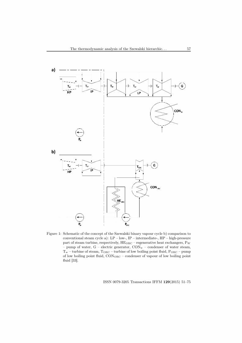
resented by the low pressure steam expansion (Fig. 1). The objective of
this concept leads: 1) to significantly reduce the exhaust area of the tur-
bine, and hence reduce the specific initial cost; and 2) to raise the power
output attainable in a single turbine unit [32,33]. Comparison conventional
steam cycle with the Szewalski concept of binary vapour cycle is presented
on Fig. 1.
So the modern steam turbine set of large output should be cut up
into two parts, between the intermediate pressure and low pressure cas-
ings (cylinders). Szewalski expected that this cut up into two parts at
a pressure level of about 0.15 to 0.4 MPa, depending on the type of the low
boiling point fluid for application in the low temperature turbine [33]. At
this pressure, steam leaving the steam turbine intermediate part (IP) of the
set is being condensed, and it is latent heat is being transferred in the heat
exchanger (HEORC) to the organic Rankine fluid (low boiling point fluid)
in order to heat it up and then to evaporate at boiling temperature. The
resulting cold vapours enters the ORC turbine (TORC) and exhausts on the
other end to ORC condenser (CONORC). After condensation the working
fluid is fed back to the heat exchanger (HEORC), a condenser-boiler, by
means of a boiler feed pump while the steam condensate is pumped back
into the steam generator [32, 33]. Thus the binary steam/low boiling point
fluid power cycle can be considered as being composed of two separate cy-
cles with steam as the working fluid in the high temperature cycle, and
a low boiling point fluid in the low-temperature one (Fig. 1b). These two
cycles are joined together by means of the heat exchanger (HEORC) which
acts as the heat sink and condenser for steam and at the same time as the
ISSN 0079-3205 Transactions IFFM 129(2015) 51–75
The thermodynamic analysis of the Szewalski hierarchic. . . 57
Figure 1: Schematic of the concept of the Szewalski binary vapour cycle b) comparison to
conventional steam cycle a): LP – low-, IP – intermediate-, HP – high-pressure
part of steam turbine, respectively, HEORC – regenerative heat exchangers, PW
– pump of water, G – electric generator, CONw – condenser of water steam,
Tw – turbine of steam, TORC – turbine of low boiling point fluid, PORC – pump
of low boiling point fluid, CONORC – condenser of vapour of low boiling point
fluid [33].
ISSN 0079-3205 Transactions IFFM 129(2015) 51–75

58 P. Ziółkowski, T. Kowalczyk, J. Hernet and S. Kornet
heat source, that is the vapour-generator, for the low temperature working
fluid [32, 33].
Because of the very small specific volume of the cold vapour, in fact
smaller by orders than the specific volume of steam at the same tempera-
ture level, the volume flow in the low-temperature turbine becomes quite
small in comparison to the volume flow in the exhaust of the conventional
condensing steam turbine. Hence, the low-temperature turbine of the bi-
nary cycle acquires only comparatively small dimensions [33]. However
from work Ziółkowski et al. [38] we know that to cut up conventional steam
turbine between intermediate pressure and low pressure casing is needed
investigation with heat flux received from the flue gases heat regeneration
system to increase ORC part of the Szewalski binary vapour cycle. This
heat flux received from the system of waste heat regeneration can be used
for heating of ORC liquid. Hence, the heat exchanger (HEORC) which acts
as the condenser for water steam and at the same time as the evaporator of
heated low boiling point fluid.
The performance of ORC systems and cycles highly depends on working
fluids properties, which affects operating condition, environmental impact,
system efficiency and economical viability [24, 33, 37]. In this work in the
selection of working fluid the attention was focused to the fact that the
working fluid operates in the subcritical cycle. For Szewalski binary vapour
cycle gabarites of devices are important so density of low boiling point fluid
becomes crucial for working fluid [32, 33]. A low density leads to higher
volume flow rate: the pressure drops in the heat exchangers are increased
and the size of the expander must be increased. This has a huge impact on
the cost of the system [8].
The working fluid must have optimum thermodynamic properties at the
range of working temperature and additionally satisfy several criteria, such
as being nontoxic, environmentally friendly, nonflammable, economical, al-
lowing a high use of the available energy from a heat source. For that rea-
sons the most adequate fluids are hydrocarbons and fluorocarbons, as well
as their mixtures. The compounds which can be selected for testing in ORC
installations are: methane, ethane, propane, butane, isobutane, n–pentane,
isopentane, n–hexane, ethylene, propylene, n–heptane, n–octane, ethanol,
carbon dioxide, nitrogen, ammonia, R236ea, R245fa, as well as a series of
other fluids used for example in refrigeration technology [8, 21, 24]. In this
paper four working fluids in the low temperature part of binary cycle such
as propane, isobutane, ethanol and ammonia were investigated. However
ISSN 0079-3205 Transactions IFFM 129(2015) 51–75

The thermodynamic analysis of the Szewalski hierarchic. . . 59
Szewalski analyzed: ammonia, freons R-21, and R-114.
3 Definition of power unit and efficiency
In this paragraph, the output power and the efficiency calculations are pre-
sented. Firstly, gross electric power of the conventional steam power unit,
Nel Gr, has been calculated on the basis of electric power produced by suc-
cessive turbine stages NelT , as follows [4, 38]:
Nel Gr =∑
NelT . (1)
Secondly, efficiency of gross production of electricity, etael Gr, has been de-
fined as an ratio of electric power generated by the conventional steam
power unit, Nel Gr, and the rate of chemical energy, Qchem = QB/ηB , in the
fuel [4, 38]
ηel Gr =NelGr
Qchem
=NelGr
mfWd
, (2)
where mf is the mass flow rate of fuel, Wd – low calorific value, ηB – boiler
efficiency; Qchem – the rate of chemical energy in the fuel supplied to the
boiler (B in Fig. 2), QB – rate of heat supplied to the cycle in the boiler.
Thermal efficiency of the cycle, ηcyc, is defined as a ratio of the difference
between rate of heat supplied to the cycle in the boiler, QB, and removed
from the cycle, QOUT , to the thermal power supplied to the cycle in the
boiler:
ηcyc =QB − QOUT
QB
. (3)
QOUT is given by the equation
QOUT = QCON +∑
Qloss + Qpip , (4)
where QCON is the rate of heat removed from the condenser,∑
Qloss – rate
of heat losses in heat exchanger, and Qpip = Qpip01−02 + Qpip04−05 – rate of
heat losses in live steam pipelines and secondary steam pipelines. Rate of
heat losses in steam pipelines, in line with Figs. 2–4, is calculated using
formula from works [4, 38, 41].
Modeling of a combustion process in the boiler was not applied in the
study and therefore additional indicator has been introduced, namely the
ISSN 0079-3205 Transactions IFFM 129(2015) 51–75

60 P. Ziółkowski, T. Kowalczyk, J. Hernet and S. Kornet
reference efficiency, ηre, defined as a ratio of gross electric power of the
conventional steam power unit, Nel Gr, to the rate of heat, QB , required to
produce steam in the boiler [4, 38] :
ηre =NelGr
QB
. (5)
The efficiency of the organic Rankine cycle has been defined as a ratio of
the specific technical work of the cycle lt, ORC to the specific rate of heat
qORC supplied to the ORC [3,30]:
ηt, ORC =lt, ORC
qORC. (6)
As a reference to the power of the entire unit the electric power of the
steam plant, NelGr, was assumed. The power of the supercritical power
plant cooperating with the ORC, NelRU , has been determined on the basis
of electric power produced in the particular stages of steam turbine, Nel T ,
and the power obtained from ORC, Nel ORC . The power obtained from the
ORC may be expressed as:
NORC = ηmηgNt, ORC −Nw,ORC , (7)
where: ηm = ηmT = ηmP is the mechanical efficiency of the ORC turbine
and the pump, Nw,ORC – is the electrical power needed to drive the addi-
tional circulation pump in the system of heat recovery.
The gross power of the system incorporating the ORC, NelRU , is the
sum of both electricity generating units
NelRU = NelGr +NORC . (8)
The final reference efficiency, ηre, has been defined as a ratio of the power
produced by conventional steam power unit Nel Gr with the power of ORC,
NORC , (as was mentioned in Eq. (8), Nel RU ) to the rate of heat, QB ,
required to produce vapour in the boiler [4, 38]:
ηre =NelRU
QB
. (9)
4 Numerical model of analyzed cycles
In this paragraph, both 900 MWe supercritical power plant, the Szewalski
binary vapour cycle and the Szewalski hierarchic vapour cycle cooperating
ISSN 0079-3205 Transactions IFFM 129(2015) 51–75

The thermodynamic analysis of the Szewalski hierarchic. . . 61
with a system of waste heat recovery from exhaust gases numerical models
are presented. All computations of the mentioned cycles have been per-
formed using the basic principles of steam systems and thermodynamic phe-
nomena modeling and algorithms for computing the properties of steam and
low boiling point fluids. So calculations of the cycles have been accomplished
for the nominal operation conditions using the CFM code [4–6,18,38–42].
The thermal cycle has been coded in on the basis of devices presented in
previous work of authors [18,38–41] . Computational procedures for each
component CFM codes belong to zero-dimensional models (0D), because
it contains an algebraically integral formulation of typical balances: mass,
momentum and energy. Additionally, CFM codes use mathematical tables
for the fluid properties [3–6,15,18,38–42]. CFM type numerical tool gives
a possibility to model combined two vapour cycles, what has recently been
demonstrated in articles [5,18,38–41].
It should be added that, despite the large number of published arti-
cles on the analysis of the steam cycle and ORC most of them are limited
to traditional resolution and none of them present a detailed analysis of
the Szewalski hierarchic vapour cycle cooperating with a waste heat recov-
ery. Several attempts for investigation have been recently presented with
steam cycle [5, 7, 9, 10, 12, 13, 31, 42], organic Rankine cycle [21, 29, 37] and
some with hybrid and binary steam/low boiling point fluid cycle [1,12–
14,22,27,28,38,40,41].
4.1 Conventional supercritical power plant
At first numerical analysis was applied to the conventional supercritical
steam power plant of the capacity of 900 MWe with the live steam parame-
ters of 30.3 MPa/653 ◦C and secondary steam respectively of 6 MPa/672 ◦C[42]. A schematic of the conventional power plant for nominal condition
with respective devices (B, HP, IP, LP, HE1–HE8, CON, P, D, G) has been
presented in Fig. 2.
In the analyzing supercritical plant (Fig. 2) there are in operations the
following fundamental devices, namely extraction-condensing turbine (HP,
IP, LP – high-, intermediate- and low-pressure part of steam turbine, re-
spectively) with generator (G) of the power of 900 MWe together with the
coal-fired steam boiler (B) with the live steam the rate of 2200 t/h. In the
system of the power plant there is also a series of other devices denoted
in scheme, such as deaerator (D), low-pressure regenerative heat exchang-
ers (HE1–HE4), high–pressure regenerative heat exchangers (HE5–HE7),
ISSN 0079-3205 Transactions IFFM 129(2015) 51–75

62 P. Ziółkowski, T. Kowalczyk, J. Hernet and S. Kornet
Figure 2: Schematic of the conventional supercritical power plant: B – boiler, HP, IP, LP
– high-, intermediate- and low-pressure part, respectively, D – deaerator, HE1–
HE4 – low-pressure regenerative heat exchangers, HE5–HE7 – high-pressure
regenerative heat exchangers, HE8 – steam cooler, P – pump, G – genera-
tor, CON – condenser of steam. Basic steam cycle analyzed in work [42] is
analogical to Fig. 1.a).
steam cooler (HE8), pump (P) and condenser of steam (CON). Addition-
ally the temperature distribution in heat exchangers (HE1-HE8) were mod-
eled, which allowed to obtain satisfactory thermodynamically parameters
in characteristic nodes (21–60) of the cycle, which confirms the accuracy of
the numerical model [5,38,40–42].
As it is shown in Tab. 1, the cycle efficiency of the 900.0 MWe – class
power plant averages between ηcyc = 0.5092 and ηcyc = 0.5091 for the lit-
erature data and the software used during modeling process, respectively.
Moreover, the gross electrical power of the supercritical power plant have
been estimated at NelGr = 899.5 MWe by means of numerical analysis.
Additionally, parameters in characteristic points (01–60 on Fig. 2) of the
ISSN 0079-3205 Transactions IFFM 129(2015) 51–75

The thermodynamic analysis of the Szewalski hierarchic. . . 63
cycle have been estimated properly (Tab. 1). The obtained results should
be regarded as satisfactory in spite of existing differences between results
from numerical code and literature data.
4.2 The Szewalski binary vapour cycle
It has been assumed that HEORC – heat exchanger in Fig. 3, in the numerical
model of Szewalski binary vapour cycle, is on one side the steam condenser
and the generator of vapour of the low-boiling point fluid (Fig. 3). The level
of condensate regeneration (HE) is constant hence temperature feeding the
boiler is constant and equal T43 = 310 ◦C. At the same time the rate of
heat to the boiler does not change, in order to produce live steam with
parameters presented in Tab. 1.
Figure 3: General schematic of the Szewalski binary vapour cycle, where additionally in
comparison to Fig. 2: TORC – turbine of organic Rankine cycle, PORC – pump of
organic Rankine cycle, CONORC – condenser of organic Rankine cycle, HEORC
– heat exchanger, which is on one side the steam condenser and the generator
of vapour of the low-boiling point fluid. Additional devices are marked in the
frame. This scheme is analogical to Fig. 1.b) [38].
ISSN 0079-3205 Transactions IFFM 129(2015) 51–75

64 P. Ziółkowski, T. Kowalczyk, J. Hernet and S. Kornet
Table 1: Comparison of the input and output data from the model and data from liter-
ature [42].
Parameter Symbol Unit Literature dataData fromthe model
Cycle efficiency ηcyc – 0.5092 0.5091Gross electric power (at generator) Nel Gr MW 900.00 899.49Reference efficiency ηre – 0.51960 0.51958Gross efficiency of production of electricity(for the case of hard coal) ηel Gr – 0.4910 0.4907Temperature of live steam at outlet from theboiler
T01◦C 653 653
Pressure of the live steam at outlet from theboiler
p01 MPa 30.3 30.3
Temperature of live steam before the turbine T02◦C 650 650
Pressure the live steam before the turbine p02 MPa 30 30Temperature of secondary steam at outlet fromboiler
T04◦C 672 672
Pressure of secondary steam at outlet from boiler p04 MPa 6 6Temperature of secondary steam before turbine T05
◦C 670 670Pressure in deaerator p24 MPa 1.15 1.15Pressure in condenser p19 MPa 0.005 0.005Pressure after the condensate pump p31 MPa 2.2 2.2Temperature of feeding water T43
◦C 310 310Internal efficiency of the group of stages of HPturbine
ηiHP – 0.90 0.90
Internal efficiency of the group of stages of IPturbine
ηiIP – 0.92 0.92
Internal efficiency of the group of stages of LPturbine
ηiLP – 0.85 0.85
Internal efficiency of the last group of stages ofLP turbine
ηiLPl – 0.80 0.80
Boiler efficiency (hard coal) ηB – 0.945 0.944Generator efficiency ηg – 0.988 0.988Mechanical losses of turbine ∆Nm MW 0.9 0.9Internal efficiency of pumps ηi P – 0.85 0.85Efficiency of regenerative heat exchangers ηHEm – 0.995 0.995–0,996Efficiency of vapour cooler ηHE – 0.995 0.994Efficiency of deaerator ηD – 1.00 1.00Flow losses in vapour pipelines to regenerativeheat exchangers and vapour cooler
ζ – 0.02 0.02
Flow losses in vapour pipeline from the vapourcooler to regenerative heat exchanger HE5
ζ59−60 – 0.01 0.01
Feedwater flow losses through regenerative heatexchangers and vapour cooler
ζloss – 0.01 0.01
Pressure loss of circulation fluid in the boiler ∆p43−01 MPa 4.2 4.2Vapour pressure loss in secondary superheater ∆p03−04 MPa 0.3 0.3Flow losses in superheated steam pipelines ζ12−03 – 0.017 0.017
ζ04−05 – 0.017 0.017Flow losses between IP and LP parts of turbine ζ06−07 – 0.01 0.01
ISSN 0079-3205 Transactions IFFM 129(2015) 51–75
The thermodynamic analysis of the Szewalski hierarchic. . . 65
In calculations of Szewalski binary vapour cycle, it has been assumed
that minimum temperature difference between the evaporating low boiling
point fluid and condensing steam is ∆T=5 K. In case of the ORC condenser
temperature of the phase change is the same as in the reference cycle, Tcon =32.8 ◦C. Moreover, the efficiencies of the elements ORC system were all set
up as following: turbine (TORC): internal ηiT = 0.90, mechanical ηmT =0.99; pump (PORC): internal ηiP = 0.85, mechanical ηmP = 0.99; generator
ηg = 0.97 and heat exchanger ηHE = 0.98. It has been additionally assumed
that condensate is not supercooled after condensation as well in condenser of
low boiling point fluid (CONORC) as in ORC heat exchanger (HEORC) [38].
The calculations of the heat cycle have been done for the constant the
live steam parameters of 30.3 MPa/653 ◦C (point 01 in Figs. 2 and 3).
Characteristic points of the conventional steam cycle (01–60) and the ORC
cycle (ORC1–ORC4) have been presented in Fig. 3.
4.3 The Szewalski hierarchic vapour cycle cooperating withthe system of heat recovery
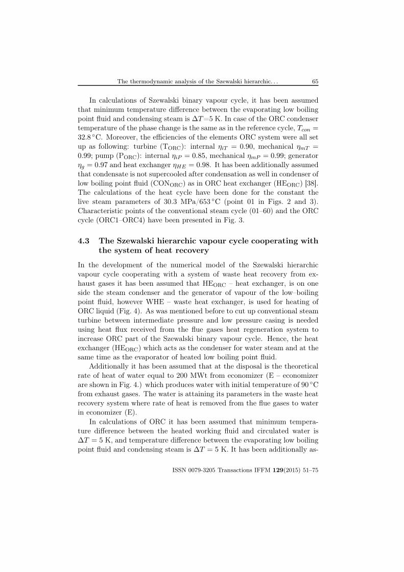
In the development of the numerical model of the Szewalski hierarchic
vapour cycle cooperating with a system of waste heat recovery from ex-
haust gases it has been assumed that HEORC – heat exchanger, is on one
side the steam condenser and the generator of vapour of the low–boiling
point fluid, however WHE – waste heat exchanger, is used for heating of
ORC liquid (Fig. 4). As was mentioned before to cut up conventional steam
turbine between intermediate pressure and low pressure casing is needed
using heat flux received from the flue gases heat regeneration system to
increase ORC part of the Szewalski binary vapour cycle. Hence, the heat
exchanger (HEORC) which acts as the condenser for water steam and at the
same time as the evaporator of heated low boiling point fluid.
Additionally it has been assumed that at the disposal is the theoretical
rate of heat of water equal to 200 MWt from economizer (E – economizer
are shown in Fig. 4.) which produces water with initial temperature of 90 ◦Cfrom exhaust gases. The water is attaining its parameters in the waste heat
recovery system where rate of heat is removed from the flue gases to water
in economizer (E).
In calculations of ORC it has been assumed that minimum tempera-
ture difference between the heated working fluid and circulated water is
∆T = 5 K, and temperature difference between the evaporating low boiling
point fluid and condensing steam is ∆T = 5 K. It has been additionally as-
ISSN 0079-3205 Transactions IFFM 129(2015) 51–75
66 P. Ziółkowski, T. Kowalczyk, J. Hernet and S. Kornet
Figure 4: General schematic of the Szewalski hierarchic vapour cycle cooperating with
a system of waste heat recovery from exhaust gases, where additionally in
comparison to Figs. 2 and 3: WHE – waste heat exchanger with use water
with temperature 90 ◦C, Pw – pump of circulated water, E – economizer which
produce water with temperature 90 ◦C from exhaust gases. Additional devices
in comparison to Fig. 2 are marked in the frame.
sumed that water, originally at temperature 90 ◦C reduces its temperature
down to 50 ◦C. Moreover, the efficiencies of the elements of ORC system,
temperature of condensing in CONORC, supercooling CONORC and HEORC,
the live steam water parameters were all set up as it is written for the Sze-
walski binary vapour cycle. Characteristic points of the conventional steam
cycle (01–60) and the ORC cycle (ORC1–ORC5) have been presented in
Fig. 4.
5 Results
The constructed numerical model of the analyzed Szewalski hierarchic vapour
cycle cooperating with a system of waste heat recovery from exhaust gases
ISSN 0079-3205 Transactions IFFM 129(2015) 51–75
The thermodynamic analysis of the Szewalski hierarchic. . . 67
has allowed carrying out a series of calculations in a wide range of variation
of thermodynamic parameters of the system. The results of calculations
have been developed in the tabular and graphical forms. Some of them are
presented below.
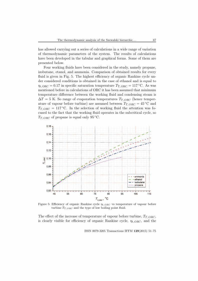
Four working fluids have been considered in the study, namely propane,
izobutane, etanol, and ammonia. Comparison of obtained results for every
fluid is given in Fig. 5. The highest efficiency of organic Rankine cycle un-
der considered conditions is obtained in the case of ethanol and is equal to
ηt,ORC = 0.17 in specific saturation temperature TT,ORC = 117 ◦C. As was
mentioned before in calculations of ORC it has been assumed that minimum
temperature difference between the working fluid and condensing steam is
∆T = 5 K. So range of evaporation temperatures TT,ORC (hence temper-
ature of vapour before turbine) are assumed between TT,ORC = 45 ◦C and
TT,ORC = 117 ◦C. In the selection of working fluid the attention was fo-
cused to the fact that the working fluid operates in the subcritical cycle, so
TT,ORC of propane is equal only 95 ◦C.
Figure 5: Efficiency of organic Rankine cycle ηt, ORC vs temperature of vapour before
turbine TT,ORC and the type of low boiling point fluid.
The effect of the increase of temperature of vapour before turbine, TT,ORC ,
is clearly visible for efficiency of organic Rankine cycle, ηt, ORC , and the
ISSN 0079-3205 Transactions IFFM 129(2015) 51–75
68 P. Ziółkowski, T. Kowalczyk, J. Hernet and S. Kornet
largest increase in efficiency – about 0.14 – occurs for temperature of vapour
before turbine TT,ORC = 117 ◦C.
The calculation results of the influence of Szewalski binary vapour cy-
cle [38], and the Szewalski hierarchic vapour cycle cooperating with a sys-
tem of waste heat recovery from exhaust gases on efficiency ηre and power
Nel RU of the whole system is presented in Fig. 6. The largest efficiency ηrein both analyzed cycles are achieved for relatively low values of tempera-
ture of condensing water Tcon,W (or temperature of vapour before turbine
TT,ORC). It should be mentioned that in heat exchanger (HEORC), which
is on one side the steam condenser and the generator of vapour of the
low–boiling point fluid, is assumed temperature difference which is equaled
∆T = Tcon,W − TT,ORC = 5 K.
The rate of heat supplied to the boiler, QB , was constant for all cases
which have been investigated so the reference efficiency, ηre, depend only on
power NelRU . This was presented on Fig. 6 – curves of reference efficiency
ηre and power NelRU overlap each other.
As was mentioned before the modern steam turbine set of large output
should be cut up into two parts, between the intermediate pressure and low
pressure cylinders. Szewalski expected that this cut up into two parts at
a pressure level of about 0.15 to 0.4 MPa, depending on the type of the
low boiling point fluid for application in the low temperature turbine. As
it was shown in the analysis from work [38], the power of the Szewalski
binary vapour cycle, the optimal value of temperature of condensing water,
Tcon,W , for cut up into two parts is for ethanol 75 ◦C, for ammonia 65 ◦C,
for isobutane 58 ◦C, for propane 55 ◦C, respectively. This temperature value
Tcon,W corresponding with pressure of water condensation, pcon,W , equals:
for ethanol 0.0386 MPa; for ammonia 0.025 MPa; for isobutane 0.0182 MPa;
for propane 0.0158 MPa.
However for the Szewalski hierarchic vapour cycle cooperating with
a system of waste heat recovery from exhaust gases (using waste heat) men-
tion values are comparised with original idea. Hence, as it was presented in
the Fig. 6, the power of the Szewalski hierarchic vapour cycle using waste
heat, the optimal value of temperature of condensing water, Tcon,W , for cut
up into two parts is for ethanol 100 ◦C, for ammonia 84 ◦C, for isobutane
74 ◦C, for propane 67 ◦C, respectively. This temperature value Tcon,W cor-
responding with pressure of water condensation, pcon,W , equals: for ethanol
0.1014 MPa; for ammonia 0.056 MPa; for isobutane 0.037 MPa; for propane
0.027 MPa.
ISSN 0079-3205 Transactions IFFM 129(2015) 51–75

The thermodynamic analysis of the Szewalski hierarchic. . . 69
Figure 6: The power of the Szewalski binary vapour cycle [38], and the Szewalski hi-
erarchic vapour cycle cooperating with a system of waste heat recovery from
exhaust gases (using waste heat) Nel RU and the reference efficiency ηre vs tem-
perature of condensing water Tcon,W and the type of low boiling point fluid.
Comparison with nominal value of conventional steam cycle which presenting
efficiency ηre and power Nel RU (continuous line) supercritical steam plant from
Fig. 2.
The calculation results clearly show that it is possible to found optimal
value of process. It should be added that because of irreversibility in heat
exchanger HEORC efficiency of Szewalski cycle is lower than nominal value
of efficiency for conventional steam cycle, which is equal ηre = 0.5196 [38].
On the other hand, the increase of overall electricity production is observed
for the Szewalski hierarchic vapour cycle using waste heat, and for all con-
sidered working fluids.
As well in Fig. 6 as in Fig. 7 was presented the reference efficiency ηrewhich has been defined by Eq. (5) for conventional steam cycle and by
Eq. (9) for Szewalski binary vapour cycle, and for the Szewalski hierarchic
vapour cycle using waste heat. The highest netto efficiency of Szewalski bi-
nary vapour cycle at the level of ηre = 0.519, ηre = 0.518 has been estimated
for ethane and ammonia respectively. Much bigger top netto efficiency is
ISSN 0079-3205 Transactions IFFM 129(2015) 51–75
70 P. Ziółkowski, T. Kowalczyk, J. Hernet and S. Kornet
obtain for the Szewalski hierarchic vapour cycle cooperating with a system
of waste heat recovery which it is estimated at the level of ηre = 0.532,ηre = 0.528 for ethane and ammonia respectively.
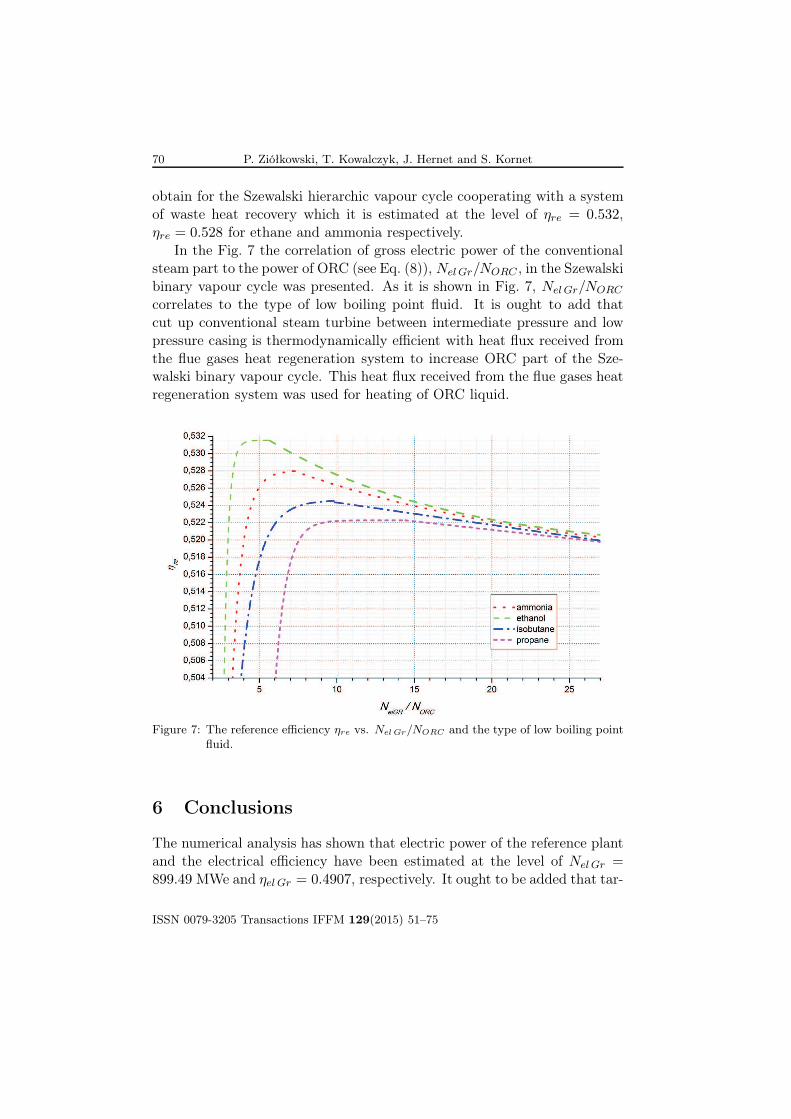
In the Fig. 7 the correlation of gross electric power of the conventional
steam part to the power of ORC (see Eq. (8)), NelGr/NORC , in the Szewalski
binary vapour cycle was presented. As it is shown in Fig. 7, NelGr/NORC
correlates to the type of low boiling point fluid. It is ought to add that
cut up conventional steam turbine between intermediate pressure and low
pressure casing is thermodynamically efficient with heat flux received from
the flue gases heat regeneration system to increase ORC part of the Sze-
walski binary vapour cycle. This heat flux received from the flue gases heat
regeneration system was used for heating of ORC liquid.
Figure 7: The reference efficiency ηre vs. Nel Gr/NORC and the type of low boiling point
fluid.
6 Conclusions
The numerical analysis has shown that electric power of the reference plant
and the electrical efficiency have been estimated at the level of NelGr =899.49 MWe and ηel Gr = 0.4907, respectively. It ought to be added that tar-
ISSN 0079-3205 Transactions IFFM 129(2015) 51–75
The thermodynamic analysis of the Szewalski hierarchic. . . 71
get values from [38,42] were respectively NelGr = 900.0 MWe and ηelGr =0.4910.
As can be seen in all considered cases the highest ORC efficiency was
obtained for the case of ethanol and is equal to ηt, ORC = 0.17 in specific
saturation temperature TT,ORC = 117 ◦C.
The highest netto efficiency of Szewalski binary vapour cycle at the level
of ηre = 0.5189, ηre = 0.5178 have been estimated [38]. Moreover, the high-
est netto efficiency is obtain for the Szewalski hierarchic vapour cycle using
waste heat which it is estimated at the level of ηre = 0.532, ηre = 0.528 for
ethane and ammonia respectively. As it was shown in the thermodynamic
analysis, the optimal value of temperature of condensing water Tcon,W for
cut up into two parts is for ethanol 10 ◦C, for ammonia 84 ◦C, for isobutane
74 ◦C, for propane 67 ◦C, respectively. This temperature value Tcon,W cor-
responding with pressure of water condensation pcon,W equals: for ethanol
0.1014 MPa, for ammonia 0.056 MPa, for isobutane 0.037 MPa, for propane
0.027 MPa. So, Szewalski hierarchic cycle using waste heat is good resolu-
tion for cooperating heat flux received from the flue gases heat regeneration
system.
Analyzing both Szewalski binary vapour cycle, and the Szewalski hier-
archic vapour cycle cooperating with a system of waste heat recovery from
exhaust gases very important are exergetic investigation. Part load charac-
teristics of the conventional steam cycle as well as Szewalski binary vapour
cycle is important information because in part load regime Szewalski binary
vapour cycle can be more efficiency than traditional steam cycle.
Received 14 March, 2015
References
[1] Aneke M., Agnew B., Underwood C.: Performance analysis of theChena binary geothermal power plant. Appl. Therm. Eng. 31(2011),
1825–1832.
[2] Angelino G., Invernizzi: Carbon dioxide power cycles using liquid nat-ural gas as heat sink. Appl. Therm. Eng. 29(2009), 2935–2941.
[3] Badur J.: Development of Energy Concept. IMP PAN Publishers,
Gdańsk 2009 (in Polish).
ISSN 0079-3205 Transactions IFFM 129(2015) 51–75

72 P. Ziółkowski, T. Kowalczyk, J. Hernet and S. Kornet
[4] Badur J.: Five lectures of contemporary fluid termomechanics. Gdańsk
2005 (in Polish).
[5] Badur J., Lemański M., Ziółkowski P., Kaczmarczyk O.: Numericalanalysis of the operating parameters of supercritical thermal cycle inpower plant Jaworzno III with heat recovery system ORC. Rep. IFFM
PASci 4/2012, Gdańsk 2012 (in Polish).
[6] Badur J.: Numerical modeling of sustainable combustion in gas tur-bines. Rep. IFFM PASci, Gdańsk 2003 (in Polish).
[7] Badyda K.: Mathematical model for digital simulation of steam turbineset dynamics and on-line turbine load distribution. Transactions IFFM
126(2014), 65–82.
[8] Bao J., Zhao L.: A review of working fluid and expander selections fororganic Rankine cycle. Renew. Sust. Energy Rev. 24(2013), 325–342.
[9] Bartela Ł., Skorek–Osikowska A., Kotowicz J.: Integration of super-critical coal–fired heat and power plant with carbon capture installationand gas turbine. Rynek Energii 100(2012), 3, 56–62 (in Polish).
[10] Bartela Ł., Skorek–Osikowska A., Kotowicz J.: Thermodynamic, eco-logical and economic aspects of the use of the gas turbine for heat sup-ply to the stripping process in a supercritical CHP plant integrated witha corbon capture installation. Energ. Convers. Manage. 85(2014), 750–
763.
[11] Bartnik R.: Thermodynamic fundamentals for production of electricpower in hierarchical j–cycle system. Transactions IFFM 126(2014),
141–151.
[12] Espatolero S., Cortés C., Romeo L.M.: Optimization of boiler cold-endand integration with the steam cycle in supercritical units. Appl. Energ.
87(2010), 1651–1660.
[13] Feidt M.: Thermodynamics of energy systems; a review and perspec-tives. J. Appl. Fluid Mech. 5(2012), 2, 85–98.
[14] Ghasemi H., Paci M., Tizzanini A., Mitsos A.: Modeling and optimiza-tion of a binary geothermal power plant. Energy 50(2013), 412–428.
[15] Głuch J.: Selected problems in determining an efficient operationstandard in contemporary heat and flow diagnostics. Pol. Marit. Res.
S1/2009, Gdańsk (2009), 22–27.
ISSN 0079-3205 Transactions IFFM 129(2015) 51–75

The thermodynamic analysis of the Szewalski hierarchic. . . 73
[16] Gnutek Z: On the Goliński-Jesionek multistage combined air/steamsystems with external combustion. Trans. IFFM 126(2014), 33–54.
[17] Horbaj P., Braunmiller G., Taus P.: On a environmentally friendlysupply of energy. Transactions IFFM 124(2014), 221–230.
[18] Jesionek K., Chrzczonowski A., Ziółkowski P., Badur J.: Enhancementof the Brayton cycle efficiency by water or steam utilization. Transac-
tions IFFM 124(2012), 93–109.
[19] Kowalczyk T., Badur J.: Hierarchical cycles in power engineering –a review of the literature. Rep. IFFM PASci 861/2014, Gdańsk 2014.
[20] Lemański M., Karcz M.: Performance of lignite-syngas operated tubularSolid Oxide Fuell Cell. Chem. Process Eng. 23(2007), 1–24.
[21] Le V.L., Feidt M., Kheiri A., Pelloux-Prayer S.: Performance opti-mization of low–temperature power generation by supercritical ORCs(organic Rankine cycles) using low GWP (global warming potential)working fluids. Energy 67(2014), 513–526.
[22] Łukowicz H., Kochaniewicz A.: Analysis of the use of waste heat ob-tained from coal-fired units in Organic Rankine Cycles and for browncoal drying. Energy 45(2012), 203–212 .
[23] Mikielewicz D., Barleta Ł., Ziółkowski P., Wajs J., Mikielewicz J.: Op-eration of the 900 MW power plant with the ORC supplied from threeheat sources. In: Aktualne Zagadnienia Energetyki, Vol. II (K. Wójs, P.
Szulc, Eds.), Wrocław University of Technology Press, 2014, 327–342.
[24] Mikielewicz D., Mikielewicz J.: A thermodynamic criterion for selec-tion of working fluid for subcritical and supercritical domestic microCHP. Appl. Therm. Eng. 30(2010), 2357–2362.
[25] Mikielewicz D., Ziółkowski P., Wajs J., Mikielewicz J.: Combined op-erations of 900 MW power plant with the ORC through the bleed steamextraction point and CO2 recovery system. In: Heat Transfer Renewable
Sources of Energy 2014, Academic Publishing House ZUT Szczecin,
2014, 380–386.
[26] Mikielewicz J.: On perspective ideas of future turbines by prof. RobertSzewalski. In: Proc. of a Jubilee Session devoted to 100th Anniversary
of Birthday of prof. Robert Szewalski, Gdańsk 2002 (in Polish).
[27] Rosyid H, Koestoer R, Putra N, Nasruddin, Mohamad, Yanuar
A.: Sensitivity analysis of steam power plant–binary cycle. Energy
35(2010), 3578–3586.
ISSN 0079-3205 Transactions IFFM 129(2015) 51–75

74 P. Ziółkowski, T. Kowalczyk, J. Hernet and S. Kornet
[28] Shokouhmand H., Atashkadi P.: Performance improvement of a single,flashing, binary, combined cycle for geothermal power plants. Energy
22(1997), 7, 637–643.
[29] Song X., Shu-ying W., Dong-sheng Z.: Slag–washing water of blastfurnace power station with supercritical organic Rankine cycle. J. Cent.
South Univ. 20(2013), 737–741.
[30] Srinivas T., Reddy: Study on power plants arrangements for integra-tion. Energy Convers. Manage. 85(2014), 7–12.
[31] Stępczyńska K., Łukowicz H., Dykas S.: Calculations of ultra-supercritical coal fired 900 MWe power unit of with waste heat recovery.Arch. Energ. 62(2012), 155–164 (in Polish).
[32] Szewalski R.: Actual problems of development of energetical technol-ogy. Enhancement of unit work and efficiency turbine and power unit.Ossolineum, Wrocław 1978 (in Polish).
[33] Szewalski R.: The binary vapour turbine set of great output, its conceptand some basic engineering problems. Transactions IFFM, 42–44(1969),
119–140.
[34] Tchanche B., Lambrinos Gr., Frangoudakis, Papadakis G.: Low-gradeheat conversion into power using organic Rankine cycles – a review ofvarious applications. Renew. Sust. Energ. Rev. 15(2011), 3963–3979.
[35] Topolski J.: Combustion diagnosis in combined gas-steam cycle. PhD
thesis, The Szewalski Institute of Fluid-Flow Machinery PASci, Gdańsk
2002 (in Polish).
[36] Vankeirsbilck I., Vanslambrouck B., Gusev S., De Paepe M.: OrganicRankine cycle as efficient alternative to steam cycle for small scalepower generation. HEFAT 2011 8th Int. Conf. on Heat Transfer, Fluid
Mechanics and Thermodynamics, July 11–13, 2011, Pointe Aux Pi-
ments, Mauritius.
[37] Vélez F., Segovia J.J., Martín M.C., Antolín G., Chejne F., Quijano A.:
A technical, economical and market review of organic Rankine cyclesfor the conversion of low-grade heat for power generation. Renew. Sust.
Energ. Rev. 16(2012), 6, 4175–89.
[38] Ziółkowski P., Hernet J., Badur J.: Revalorization of the Szewalskibinary vapour cycle. Arch. Thermodyn. 35(2014), 3, 225–249.
ISSN 0079-3205 Transactions IFFM 129(2015) 51–75

The thermodynamic analysis of the Szewalski hierarchic. . . 75
[39] Ziółkowski P., Lemański M., Badur J., Nastałek L.: Power augmenta-tion of PGE Gorzow gas turbine by steam injection – thermodynamicoverview. Rynek Energii 98(2012), 161–167.
[40] Ziółkowski P., Mikielewicz D.: Thermodynamic analysis of the super-critical 900 MWe power unit, co–operating with an ORC cycle. Arch.
Energ. 62(2012), 165–174 (in Polish).
[41] Ziółkowski P., Mikielewicz D., Mikielewicz J.: Increase of power and ef-ficiency of the 900 MW supercritical power plant through incorporationof the ORC. Arch. Thermodyn. 34(2013), 4, 51–71.
[42] The reference cycle for the activities within the Strategic Project Con-tract SP/E/1/67484/10. Institute of Machinery and Power Equipment,
Silesian University of Technology, Gliwice 2011.
ISSN 0079-3205 Transactions IFFM 129(2015) 51–75


![Exergy analysis of the Szewalski cycle with a waste …...eters of the Szewalski binary vapour cycle was performed by Kowalczyk et al.[3], who presented the energy and exergy analysis](https://img.dokumen.tips/doc/110x75/5f36873b62461f4a731f3996/exergy-analysis-of-the-szewalski-cycle-with-a-waste-eters-of-the-szewalski-binary.jpg)