Embed Size (px)
Citation preview

This material is for informational purposes only and subject to change without notice. It describes Ixia’s present plans to develop and make
available to its customers certain products, features and functionality. Ixia is only obligated to provide those deliverables specifically included in a
written agreement between Ixia and the customer. ©2012 Ixia. All rights reserved.
1
The Test of Time
Testing the Functionality, Timing Accuracy,
Performance, and Scalability of IP/Ethernet
Networks Jarek Zdziech, Systems Engineer, Ixia
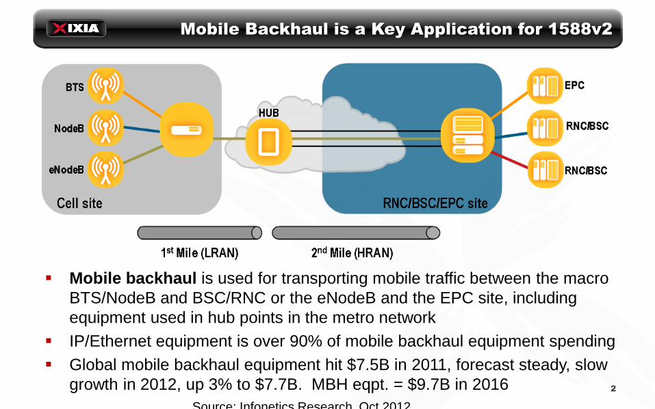
Mobile Backhaul is a Key Application for 1588v2
Mobile backhaul is used for transporting mobile traffic between the macro
BTS/NodeB and BSC/RNC or the eNodeB and the EPC site, including
equipment used in hub points in the metro network
IP/Ethernet equipment is over 90% of mobile backhaul equipment spending
Global mobile backhaul equipment hit $7.5B in 2011, forecast steady, slow
growth in 2012, up 3% to $7.7B. MBH eqpt. = $9.7B in 2016
2
Source: Infonetics Research, Oct 2012

IP/Ethernet Mobile Backhaul Deployment
Drivers • Lower the costs of growing mobile data traffic
• Accommodate the 3G mobile broadband data
transition
• Move to IP as the basic technology of LTE
(and WiMAX)
IP/Ethernet growth • 94% of 2012 MBH equipment spending is
IP/Ethernet gear, and 58% of that is packet
microwave
• ~200 mobile operators are actively deploying
IP/Ethernet backhaul in 2012, up from 150 in
2011, 100 in 2010, and 25 in 2009
Most carriers aggressively deploying
1588v2, others using TDM and or GPS
to provide timing while not fully
migrated
Source: Infonetics Research, Oct 2012
MEF: Migration to IP/Ethernet

Mobile Backhaul key application of timing over
packet
4
Source: Infonetics Mobile Backhaul Equipment and Services (2012)
Ethernet Synchronization Solutions
Physical layer (SyncE)
• Use a synchronized clock for Ethernet PCS
Packet layer for frequency
• CES, SAToP, Pseudo-wire
Packet layer for time & frequency
• PTP, NTP
Focus here is mainly on PTP (1588v2)
5

Ixia 1588v2/PTP Emulation
6
1588v2 device types: Master, Boundary,
Transparent and Slave
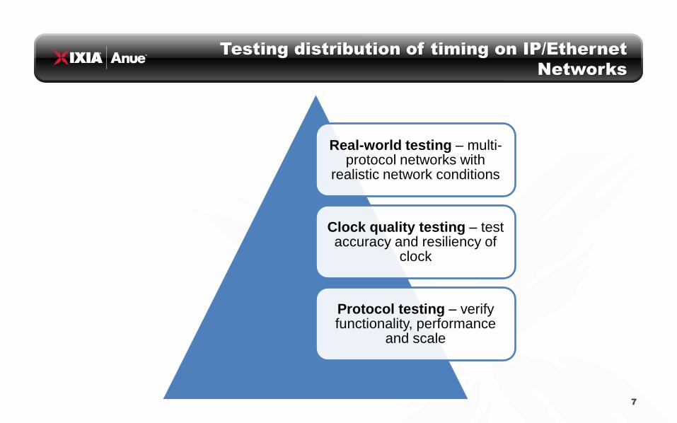
Testing distribution of timing on IP/Ethernet
Networks
Real-world testing – multi-protocol networks with
realistic network conditions
Clock quality testing – test accuracy and resiliency of
clock
Protocol testing – verify functionality, performance
and scale
7

1588v2 Protocol Testing - Master
8
Testing a Grand Master Clock
• 1588v2 is a “tool box” with many options
• Ethernet, IPv4 or IPv6
• Multicast or Unicast
• Delay-Request/Response, Peer Delay or One-way
• Priority: 802.3P, IP ToS or DiffServ
• clock parameters
• Configurable message rates Sync @ 1/32s vs Sync @ 1/128 = message rates 4x
faster per slave if unicast
• Becoming more common to require a profile like Telecom Profile G.8265.1 for frequency
• Need to make key measurements: min/max/ave offset, path delay, all message counters and rates
• Slave scalability – need to be able to capacity plan

1588v2 Protocol Testing - Slave
9
Testing Slave Clocks • Ethernet, IPv4 or IPv6
• Multicast or Unicast
• One-step or Two-step
• Delay-Request/Response, Peer Delay or One-way
• Priority: 802.3P, IP ToS or DiffServ
• All clock parameters including BMC
• Messages rates: Sync Interval Log -9 (512/s) to Log 9 (1
per 512s)
Announce Interval Log -9 (512/s) to Log 9 (1 per 512s)
Delay Request Interval Log -9 (512/s) to Log 9 (1 per 512s)
• Telecom Profile G.8265.1 parameters
• Key measurements: min/max/ave offset, path delay, all message counters and rates
• Test Best Master Clock algorithm

1588v2 Protocol Testing – Boundary and
Transparent
10
Test boundary clock ability to be slave to the master and master to connected slaves
Test transparent clock ability to accurately modify the correction field (CF) of each PTP packet

Clock Quality in a 1588v2 Network
Time (frequency, phase, ToD) is distributed from PTP Master, and recovered at the
slave device for use by remote network equipment
Packet network between master and slave includes a number of switches or routers
• Causes non-linear timing impairment, known as PDV, due to traffic congestion, queuing, etc.
• Boundary Clocks and Transparent Clocks are PTP-aware switches with on-path support that
can reduce the effect of PDV on a synchronization network
PTP Master
GPS Receiver
PTP Slave
PTP Network
(n-1) (n) (n+1)
T0
x(n) x(n+1)x(n-1)
Reference Freq / Phase
Recovered Freq / Phase
Switch Switch Switch

Synchronization Networks – Wander
Wander
• Physical-layer deviation of a clock signal compared with a reference
If linear, indicates an offset; If time-varying, viewed in terms of frequency
• Measured with Time Interval Error (TIE)
MTIE & TDEV are calculated from TIE data
• Wander is a property of a physical clock
• Clocks recovered from Ethernet packet network may have wander
Must be evaluated using TIE, MTIE and TDEV
Limits and masks defined by ITU-T standards
Wander of the recovered clock is often caused by PDV
• Use of boundary clocks & transparent clocks reduces the effect of PDV

Clock Quality - MTIE & TDEV
Wander is evaluated using two metrics: MTIE and TDEV
• Amplitude is in units of time (ns), against an observation interval “tau”
The TIE data is analyzed in progressively larger windows or intervals of time,
which are plotted on the X axis
“Tau” is the width (in time) of this window from which the value of MTIE or
TDEV is calculated
Tau is related to time, but is not the same as time!
• MTIE – Maximum Time Interval Error Maximum difference of any two data points within the given value of tau
Useful indicator of buffer size, cumulative frequency offsets
• TDEV – Time Deviation Represents the spectral content of the TIE data
Useful indicator of periodic effects
• ITU-T standards specify masks for testing MTIE and TDEV 13
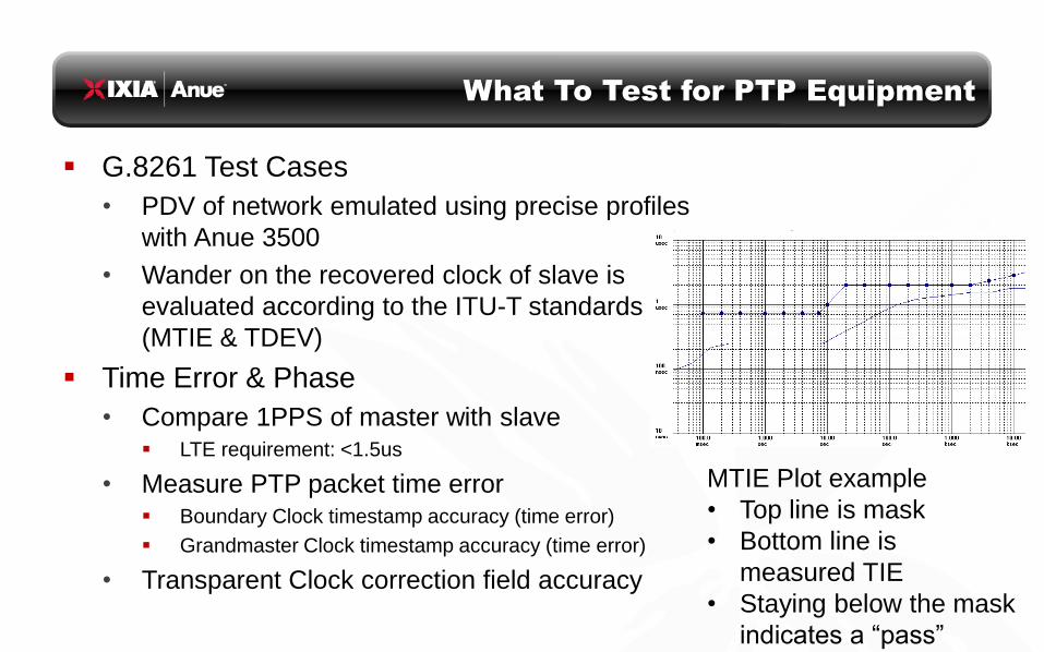
What To Test for PTP Equipment
G.8261 Test Cases
• PDV of network emulated using precise profiles
with Anue 3500
• Wander on the recovered clock of slave is
evaluated according to the ITU-T standards
(MTIE & TDEV)
Time Error & Phase
• Compare 1PPS of master with slave LTE requirement: <1.5us
• Measure PTP packet time error Boundary Clock timestamp accuracy (time error)
Grandmaster Clock timestamp accuracy (time error)
• Transparent Clock correction field accuracy
MTIE Plot example
• Top line is mask
• Bottom line is
measured TIE
• Staying below the mask
indicates a “pass”

Slave Clock – Testing to G.8261
Slave Clock (aka Ordinary Clock) Functionality
• Receives timestamps from sync and follow-up packets from master
• Calculates network delay using delay request, delay response sequence Time at the slave is compensated using this calculated one-way delay
Asymmetry due to rate adaptation, load balancing, etc. can cause time/phase error
• Delivers the recovered clock to the host or network Traditional slave clock delivers synchronization
• Frequency – 2.048MHz, T1, E1
• Phase – 1PPS aligns “top of the second” for time synchronization
Embedded slave may deliver time to the host such as a switch/router or server
• PDV in the network affects recovered clock accuracy Slave clocks are normally tested using G.8261 test cases
PDV is added according to G.8261 test case between master and slave
Recovered clock interface is measured for accuracy and compared to a mask

Boundary Clock – Testing Timestamp Error
Boundary Clock Functionality
• Switch or router at network boundary (subnet, provider edge, etc.)
• Derives frequency and time from slave port connected to a Grand
Master clock through the network
• Provides sync (frequency & time) on one or more master ports
connected to slaves downstream Time stamps in outgoing sync/followup packets are generated by the BC using its PTP
implementation.
Potential for timestamp error – same effect as PDV
• Caused by: queuing delays, inaccurate clock recovery, network congestion, etc.
• These non-linear timing errors that cannot be distinguished from PDV and have
the same effect at slave device as PDV (causes wander)
• Timestamp error of Boundary Clocks must be evaluated

Transparent Clock – Testing Correction Field
Accuracy
Transparent Clock Functionality
• Ethernet switch positioned between PTP devices
• Transparent Clock calculates the residence time, amount of time a PTP
packet is delayed as it is forwarded through the switch
• Residence time is added to the PTP packet’s correction field Multiple TCs in a network may each increment the correction field as a PTP packet
makes its way through the network
• Correction field of PTP packet is used by slave to compensate for PDV
Potential for correction field error
• Inaccuracy in the correction field can reduce the effectiveness of the
transparent clock to remove the cumulative effects of PDV
• Correction Field accuracy must be evaluated

MWC 2012 Demo of 1588v2
18
Scalable frequency and phase
synchronization
Rapid clock re-alignment after failover
Robust under real-world conditions
High performance under heavy traffic
Video: http://www.ixiacom.com/ixiatv/customer_testimonials/index.php

EANTC testing for Carrier Ethernet World Congress 2012
Test Case this year included • Testing Boundary Clocks
• Testing Transparent Clocks
• Testing hybrid mode (PTP and SyncE)
• Testing Ethernet Microwave transport
• Tested best master selection
• New measurement metrics and impairment profiles
• G.8265.1 Telecom Profile was tested but did not have wide vendor support
• G.8275.1 for Phase was not yet ratified
Issues • Boundary clocks did not have
compatible feature set (one had one-step only, the other had two-step clock)
• Limited support for G.8265.1 Telecom Profile
• Transparent Clock inserted a constant value for correction factor
Successes • Several transparent clocks
tested successfully
• PTP and SyncE hybrid tested successfully
• PTP over Ethernet Microwave tested successfully
19

ISPCS Plug-Fest 2012
Many participating vendors requesting testing of basic Master and Slave clock implementations
IxNetwork was used to run slave scalability tests for master clocks
Both IxNetwork and Anue 3500 were used to test accuracy of transparent clocks
Tested PTP over Ethernet/VLAN, IPv4 and IPv6 – found issues with IPv6
Only a few Boundary clock implementations
Significant interest in the Power Profile
Interest in AVB( 802.1AS) using PTP for Audio-Video bridging
20

This material is for informational purposes only and subject to change without notice. It describes Ixia’s present plans to develop and make
available to its customers certain products, features and functionality. Ixia is only obligated to provide those deliverables specifically included in a
written agreement between Ixia and the customer. ©2012 Ixia. All rights reserved.
Thank You!
Questions?
www.ixiacom.com
21